1 THE STATE OF NEW HAMPSHIRE BEFORE THE PUBLIC UTILITIES COMMISSION PETITION OF PUBLIC SERVICE COMPANY OF NEW HAMPSHIRE D/B/A EVERSOURCE ENERGY FOR LICENSES TO CONSTRUCT AND MAINTAIN ELECTRIC LINES, NEUTRAL WIRE AND FIBER OPTIC CABLE OVER AND ACROSS THE PUBLIC WATERS OF THE OYSTER RIVER AND LITTLE BAY IN THE TOWN OF DURHAM, NEW HAMPSHIRE AND PICKERING BROOK AND LITTLE BAY IN THE TOWN OF NEWINGTON, NEW HAMPSHIRE. TO THE PUBLIC UTILITIES COMMISSION: Public Service Company of New Hampshire d/b/a Eversource Energy (“PSNH”), a public utility engaged in the generation, transmission, distribution and sale of electricity in the State of New Hampshire, hereby petitions the Public Utilities Commission (“Commission”), pursuant to RSA 371:17, for licenses to construct and maintain electric lines, neutral wire and fiber optic cable at three locations over or under, and across, public waters in the Towns of Durham and Newington, New Hampshire, and in support of its petition states as follows: 1. In order to meet the reasonable requirements of service to the public, PSNH has previously constructed and currently operates and maintains three 34.5 kV lines in the New Hampshire Seacoast Region, designated as Lines 380, 3162 and 3850. Line 380 runs between PSNH’s Madbury Substation in Madbury, New Hampshire to PSNH’s Packers Falls Substation in Durham, New Hampshire. Line 3162 runs from PSNH’s Packers Falls Substation to Little Bay in Durham, New Hampshire. Line 3850 runs from PSNH’s Portsmouth Substation in Portsmouth, New Hampshire to Little Bay in Newington, New Hampshire. Additionally, on the National Oceanographic and Atmospheric Administration (NOAA) Chart #13285 there is an existing charted underwater cable corridor across Little Bay, which is located between the shoreline proximate to the 3162 Line right of way in Durham, and the shoreline proximate to the 3850 Line right of way in Newington. A copy of this NOAA Chart is attached to this petition as Exhibit 8. Lines 380, 3162 and 3850 are an integral part of the PSNH distribution system serving the New Hampshire Seacoast Region. 2. In order to continue to meet the reasonable requirements of service to the public, PSNH has determined it is necessary to install a new 115kV line from the Madbury Substation in Madbury, New Hampshire to the Portsmouth Substation in Portsmouth, New Hampshire, to be designated as Line “F107”. Line F107 is needed to provide a parallel path to enhance the existing 115 kV loop between the Deerfield and Scobie Pond Substations in order to address reliability concerns in the New Hampshire Seacoast Region, which have previously been identified by the Independent System Operator – New England (“ISO-NE”). PSNH, working with ISO-NE, conducted a needs assessment study which concluded that the New Hampshire Seacoast Region requires
Transcript
1
THE STATE OF NEW HAMPSHIRE BEFORE THE
PUBLIC UTILITIES COMMISSION
PETITION OF PUBLIC SERVICE COMPANY OF NEW HAMPSHIRE D/B/A EVERSOURCE ENERGY FOR LICENSES TO CONSTRUCT AND MAINTAIN ELECTRIC LINES, NEUTRAL WIRE AND FIBER OPTIC CABLE OVER AND ACROSS THE PUBLIC WATERS OF THE OYSTER RIVER AND LITTLE BAY IN THE TOWN OF DURHAM, NEW HAMPSHIRE AND PICKERING BROOK AND LITTLE BAY IN THE TOWN OF NEWINGTON, NEW HAMPSHIRE. TO THE PUBLIC UTILITIES COMMISSION: Public Service Company of New Hampshire d/b/a Eversource Energy (“PSNH”), a public utility engaged in the generation, transmission, distribution and sale of electricity in the State of New Hampshire, hereby petitions the Public Utilities Commission (“Commission”), pursuant to RSA 371:17, for licenses to construct and maintain electric lines, neutral wire and fiber optic cable at three locations over or under, and across, public waters in the Towns of Durham and Newington, New Hampshire, and in support of its petition states as follows: 1. In order to meet the reasonable requirements of service to the public, PSNH has previously constructed and currently operates and maintains three 34.5 kV lines in the New Hampshire Seacoast Region, designated as Lines 380, 3162 and 3850. Line 380 runs between PSNH’s Madbury Substation in Madbury, New Hampshire to PSNH’s Packers Falls Substation in Durham, New Hampshire. Line 3162 runs from PSNH’s Packers Falls Substation to Little Bay in Durham, New Hampshire. Line 3850 runs from PSNH’s Portsmouth Substation in Portsmouth, New Hampshire to Little Bay in Newington, New Hampshire. Additionally, on the National Oceanographic and Atmospheric Administration (NOAA) Chart #13285 there is an existing charted underwater cable corridor across Little Bay, which is located between the shoreline proximate to the 3162 Line right of way in Durham, and the shoreline proximate to the 3850 Line right of way in Newington. A copy of this NOAA Chart is attached to this petition as Exhibit 8. Lines 380, 3162 and 3850 are an integral part of the PSNH distribution system serving the New Hampshire Seacoast Region.
2. In order to continue to meet the reasonable requirements of service to the public, PSNH has determined it is necessary to install a new 115kV line from the Madbury Substation in Madbury, New Hampshire to the Portsmouth Substation in Portsmouth, New Hampshire, to be designated as Line “F107”. Line F107 is needed to provide a parallel path to enhance the existing 115 kV loop between the Deerfield and Scobie Pond Substations in order to address reliability concerns in the New Hampshire Seacoast Region, which have previously been identified by the Independent System Operator – New England (“ISO-NE”). PSNH, working with ISO-NE, conducted a needs assessment study which concluded that the New Hampshire Seacoast Region requires
2
additional transmission capacity to support the reliable delivery of electric power to meet the region’s current demand and future increased demand. The approximate in-service date for this new line is in the 4th Quarter of 2018. Installing this new transmission line will allow PSNH to continue to provide reliable electric service to its customers in this area of the State.
3. The F107, as presently proposed, will cross public water bodies at two (2) locations in the Town of Durham, one over the Oyster River and one under Little Bay, and at two (2) locations in the Town of Newington, one over Pickering Brook and one under Little Bay.1 The overhead Oyster River crossing will be double circuited with Line 380, which currently crosses the Oyster River at this location. The 3850 Line which currently crosses Pickering Brook at this location will be rebuilt offset from the existing location.2 This will allow for the overhead Pickering Brook crossing of the F107 Line as a single circuit line, parallel to the 3850 Line, on separate structures. The crossing of Little Bay will be installed underwater in the existing cable crossing area. Four existing underwater cables were previously installed in this corridor, but were later de-energized and disconnected from existing circuits, and have been abandoned in place. 4. In order to improve and enhance the reliability and capacity of the communications system used in its electric system operations, and thereby meet the reasonable requirements of service to the public, PSNH will also install and maintain an optical ground wire, known as OPGW cable, on its new overhead Line F107 structures, which will cross the same public water bodies at the same locations as the F107 overhead crossings. In addition to communications capabilities, the OPGW will provide lightning protection over the conductors in the overhead configurations. Two ADSS (All Di-Electric Self Supporting) fiber optic cables will be installed with the underwater cable crossings in Little Bay to complete the communication path. 5. At the overhead crossings of the Oyster River and Pickering Brook, the existing 380 and 3850 line pole structures will be replaced with new double circuit or single circuit, single pole structures designed to handle the loads of supporting the 115 kV F107 and/or 34.5 kV 380 and 3850 lines. The F107 Line overhead crossing will be built with 1590 kcmil ACSR 45/7 conductor, and the 380 Line and 3850 Line crossings will be built with 477 kcmil ACSR 18/1 conductor. The 380 Line has also been designed to accommodate 795 ACSR 26/7 conductor, with no change in clearances, which may be required based on anticipated future needs that may coincide with the timing of this project. The F107 Line underwater crossing of Little Bay will be constructed with three 1400mm2 cross link polyethylene (XLPE) , lead sheath, armored submarine cables with
1 The town line between Durham and Newington bisects Little Bay, resulting in the location of the Little Bay underwater crossing in both Towns. 2 Due to oversight or to the application of different public waters or navigability crossing criteria at the time of original construction, neither the existing 380 Line crossing of the Oyster River, nor the existing 3850 Line crossing of Pickering Brook have been previously licensed by the Commission; however, each of these crossings will be licensed under this petition.
3
one cable per phase. As noted above, F107 will support an optical ground wire (OPGW) for its entirety. At the underwater crossing of Little Bay the OPGW will be spliced with two ADSS cables to complete the submarine crossing. 6. The location maps, design and proposed construction plan and profile drawings, and required clearance calculations for each of the new crossings of the Oyster River, Pickering Brook and Little Bay are attached to this petition as Appendices A, B and C, respectively. 7. The required technical information provided in this petition is based on the 2012 National Electrical Safety Code (NESC) C2-2012. The proposed crossings have been designed and will be constructed, maintained and operated by PSNH in accordance with the applicable requirements of the NESC.
8. Each of the crossings will be spanned using steel structures, excepting the easterly side of the Little Bay crossing, which will terminate at a manhole structure, and the 34.5kV crossing of Pickering Brook, which will use wood pole structures. Detail designs of these crossings and structure details have been outlined in the Appendices A, B and C for each of the water crossings. 9. Flood water elevations for the crossings were based on information contained in flood insurance rate maps obtained from FEMA. Table 232-1 of the NESC states that the minimum clearance over a water body is based on a 10-yr flood elevation. All elevations provided are based on NAVD88 datum. All location information is based on NAD 83 datum.
10. Based on Table 232-1 of the NESC, for open supply conductors 750 V to 22 kV to ground, the minimum clearance to the water surface during normal flood level (10-yr flood, or as assumed, for the purpose of this petition) is 20.5 feet (for waters less than 20 acres), 28.5 feet (for waters 20-200 acres), and 34.5 feet (for waters 200-2000 acres). NESC Rule 232.C.1.a states that an additional clearance of 1.6 feet or [(69.7 kV-22 kV)x 0.4] is needed for 115 kV, which brings the total required minimum clearance to 22.1 feet, 30.1 feet, and 36.1 feet, respectively. For overhead shield/surge protection wires that meet NESC Rule 230.C.1, the minimum clearance to the water surface at the normal flood level is 17.5 feet and 25.5 feet respectively. As the static wires are located above the phase wires at all crossings, this NESC minimum clearance requirement will always be met. Based on Table 232-1 of the NESC, neutral conductors 0V to 300V shall have a clearance to ground of 15.5ft, and open supply conductors 750 V to 22 kV to ground shall have a minimum clearance to roads subject to truck traffic of 18.5 feet. With the additional 1.6’ of clearance required for 115 kV, the total required clearance to roads subject to truck traffic is 20.1 feet. Based on Table 352-1 of the NESC, underground direct bury cable over 50kV shall have a burial depth of 42 inches. Section 351.C.5 of the NESC also states that “Submarine crossings should be routed, installed, or both, so they will be protected from erosion by tidal action or currents. They should not be located where ships normally anchor.” Per Table 341-1 of the NESC, cable with a supply voltage of 50,001 V to 120,000 V shall be no closer than 12 inches, surface to
4
surface, in underground manholes and vaults. NESC Rule 341.B.1.c also requires cables to be at least 3 inches above the floor of a manhole or vault.
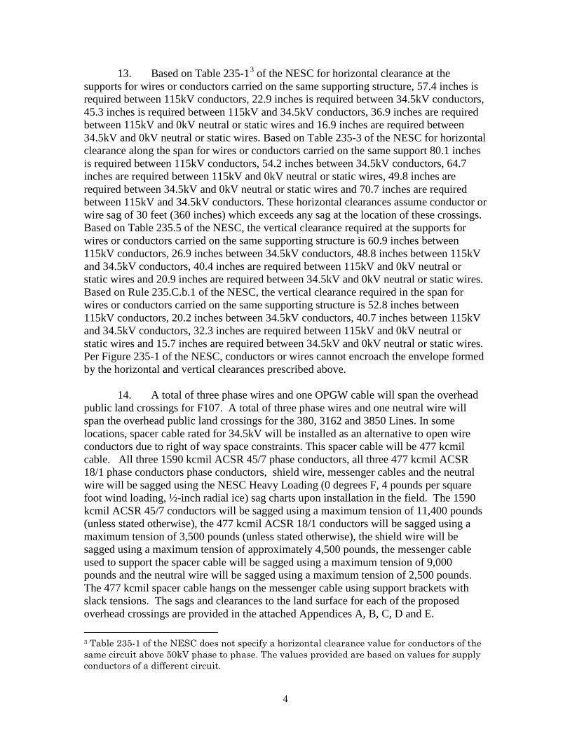
11. Based on Table 235-13 of the NESC for horizontal clearance at the supports for wires or conductors carried on the same supporting structure, 57.4 inches is required between 115kV conductors, 22.9 inches is required between 34.5kV conductors, 45.3 inches is required between 115kV and 34.5kV conductors, 36.9 inches are required between 115kV and 0kV neutral or static wires and 16.9 inches are required between 34.5kV and 0kV neutral or static wires. Based on Table 235-3 of the NESC for horizontal clearance along the span for wires or conductors carried on the same support 80.1 inches is required between 115kV conductors, 54.2 inches between 34.5kV conductors, 64.7 inches are required between 115kV and 0kV neutral or static wires, 49.8 inches are required between 34.5kV and 0kV neutral or static wires and 70.7 inches are required between 115kV and 34.5kV conductors. These horizontal clearances assume conductor or wire sag of 30 feet (360 inches) which exceeds any sag at the location of these crossings. Based on Table 235.5 of the NESC the vertical clearance required at the supports for wires or conductors carried on the same supporting structure is 60.9 inches between 115kV conductors, 26.9 inches between 34.5kV conductors, 48.8 inches between 115kV and 34.5kV conductors, 40.4 inches are required between 115kV and 0kV neutral or static wires and 20.9 inches are required between 34.5kV and 0kV neutral or static wires. Based on Rule 235.C.b.1 of the NESC the vertical clearance required in the span for wires or conductors carried on the same supporting structure is 52.8 inches between 115kV conductors, 20.2 inches between 34.5kV conductors, 40.7 inches between 115kV and 34.5kV conductors, 32.3 inches are required between 115kV and 0kV neutral or static wires and 15.7 inches are required between 34.5kV and 0kV neutral or static wires. Per Figure 235-1 of the NESC conductors or wires cannot encroach the envelope formed by the horizontal and vertical clearances prescribed above.
12. A total of three phase wires and one OPGW cable will span the overhead water crossings for F107. A total of three phase wires and one neutral wire will span the overhead water crossings for the 380 and 3850 lines. All three 1590 kcmil ACSR 45/7 phase conductors, all three 477 kcmil ACSR 18/1 phase conductors, shield wire and the neutral wire will be sagged using the NESC Heavy Loading (0 degrees F, 4 pounds per square foot wind loading, ½-inch radial ice) sag charts upon installation in the field. The 1590 kcmil ACSR 45/7 conductors will be sagged using a maximum tension of 11,400 pounds (unless stated otherwise), the 477 kcmil ACSR 18/1 conductors will be sagged using a maximum tension of 3,500 pounds (unless stated otherwise), the shield wire will be sagged using a maximum tension of approximately 4,500 pounds and the neutral wire will be sagged using a maximum tension of 2,500 pounds. The sags and clearances to the water surface for each of the proposed overhead crossings are provided in the attached Appendices. 3 Table 235-1 of the NESC does not specify a horizontal clearance value for conductors of the same circuit above 50kV phase to phase. The values provided are based on values for supply conductors of a different circuit.
5
13. The entire project is being permitted with the New Hampshire Department of Environmental Services (NHDES) and US Army Corps of Engineers (USACE). None of the new crossing structures will be set within jurisdictional wetlands, although two structures will be set in or near shoreland protection areas. The underwater cable crossing of Little Bay will also require NHDES and USACE wetlands permitting. The appropriate wetlands permits will be applied for and obtained by PSNH prior to the installation of any of the new structures associated with the crossings, in conjunction with PSNH’s siting application. Wetland permits are required to gain access to several of the new crossing structures, such permits will likewise be obtained by PSNH prior to construction. The Line F107 crossings are subject to approval and the issuance of a certificate of site and facility by the New Hampshire Site Evaluation Committee (NHSEC) as part of PSNH’s Seacoast Reliability Project filing. All approvals as part of that process will be obtained prior to construction.
14. For each of the overhead crossings, PSNH owns a permanent, minimum 100 foot wide easement for its lines and facilities on both sides of the public water body at the proposed crossing locations. Each of the crossings will be constructed within the limits of those easements. On the westerly side of the Little Bay crossing, the riser pole structure will be located on PSNH fee-owned land which PSNH will acquire and own at time of construction approval.4 The proposed crossing location of Little Bay will occur in an existing 1000 feet wide cable area as defined on the NOAA Chart #13285, Exhibit 8. On the easterly side of the Little Bay, the crossing will come ashore and terminate in a manhole structure within a permanent 100 foot wide easement which PSNH will acquire and own at time of construction approval.5 15. PSNH submits that the licenses petitioned for herein may be exercised without substantially affecting the rights of the public in the public waters listed in this petition. Minimum safe line clearances above and below all water surfaces and affected shorelines will be maintained at all times. The use and enjoyment by the public of the public waters of the Oyster River, Pickering Brook and Little Bay will not be diminished in any material respect as a result of the overhead line and underwater cable crossings. WHEREFORE, PSNH respectfully requests that the Commission:
a. Find that the licenses petitioned for herein may be exercised without substantially affecting the public rights in the public waters which are the subject of this petition;
4 PSNH has contracted with the shoreline landowner to acquire fee ownership of the westerly shore parcel, and therefore controls the necessary land rights in this location for the proposed crossing. 5 PSNH has contracted with the easterly shoreline landowner for the purchase of the necessary easement rights, and therefore controls the necessary land rights in this location for the proposed crossing.
6
b. Grant PSNH licenses to construct and maintain electric lines, neutral wire and fiber optic cable over, under and across the public waters as specified in the petition; and
c. Issue an Order Nisi and orders for its publication; and, d. Grant such other and further relief as may be just and equitable. Dated at Manchester this 9th day of March, 2016.
Respectfully submitted, PUBLIC SERVICE COMPANY OF NEW
HAMPSHIRE d/b/a EVERSOURCE ENERGY
___________________________________ Christopher J. Allwarden Senior Counsel, Legal Department
Eversource Energy Service Company 780 North Commercial Street Manchester, NH 03101 (603) 634-2459
7
APPENDIX A
F107 & 380 Lines OYSTER RIVER DURHAM, NH
1. The design and proposed construction of this crossing is shown on the
attached PSNH Transmission Business Drawing entitled “DOUBLE CKT F107 & 380 BETWEEN STR. 28 & 29 OYSTER RIVER, DURHAM, NEW HAMPSHIRE” (Drawing No. F10740901) marked as Exhibit 1.
2. The location of the double circuit F107 and 380 crossing is shown on the
attached Location Plan marked as Exhibit 2.
3. Line F107 and 380 will cross the Oyster River on a 1-pole, direct embed, 110 foot pole (16.5 feet embedded), steel tangent suspension structure (northern side) and on a 1-pole, 100 foot, steel deadend strain structure on concrete foundation (southern side). Details of these structures are shown on Exhibit 1. As shown on Exhibit 1, for Structure 28 the 115kV phase wires have an approximate separation at the structure of 7 -15 feet vertically and 0-13 feet horizontally in a delta configuration. The static wire is carried on the structure by a support bracket approximately nine inches down from the top of the structure. The 34.5kV phase wires are arranged horizontally approximately 15 feet below the lowest 115kV conductor and have an approximate separation at the structure of 0-5 feet vertically and 3-6 feet horizontally. The neutral wire is carried on the structure by a support bracket approximately seven feet down below the 34.5kV phase wires. As shown on Exhibit 1, for Structure 29 the 115kV phase wires have an approximate separation at the structure of 7 -15 feet vertically and 3-20 feet horizontally in a delta configuration. The static wire is carried on the structure by a support bracket approximately six inches down from the top of the structure. The 34.5kV phase wires are arranged horizontally approximately 16 feet below the lowest 115kV conductor and have an approximate separation at the structure of zero feet vertically and five feet horizontally. The neutral wire is carried on the structure by a support bracket approximately seven feet down below the 34.5kV phase wires. All NESC clearances at the structure, as described in paragraph 11 of the petition, have been met by exceeding the horizontal and/or vertical clearances required. Land along the shoreline between the structures of this crossing and the river is not traversable by vehicles. However, minimum distances to ground per the NESC have been met. A clearance of 24 feet between the neutral and the closest ground point has been provided. This exceeds the NESC required clearance of 15.5 feet by 8.5 feet. As all other phase wires are above this elevation they will always exceed the NESC required clearance.
4. Flood water elevations for the Oyster River were based on information contained in flood insurance rate maps provided by FEMA. Flood elevations are based on FEMA FIRM Map 33017C0314D Panel 314 or 405 dated May 17, 2005 and FEMA FIS Study 33015CV001A Dated May 17, 2005. The 10-year flood elevation for this portion
8
of the river is approximately 33.3 feet. The area of the crossing, as required by the NESC (Section 232), is approximately 38.1 acres (314 feet x5280 feet/43560sf/acre). As stated in paragraph 10 of the petition, the minimum required 115 kV conductor clearance for water surface areas between 20-200 acres is 30.1 feet for 115 kV, and 28.5 feet for 34.5 kV. 5. The sags and clearances to the water surface during a 10-year flood event for this crossing are as follows;
• PSNH has investigated a multitude of weather and loading conditions for its design. PSNH used these design conditions and combinations thereof to determine the minimum clearance of all conductors to the water and land surfaces, between the phase conductors and OPGW cable and neutral conductors. PSNH has determined that the weather cases and combinations listed below result in the minimum clearance and control over all other weather conditions and combinations.
• Shield wires – Due to the fact that the OPGW wire is located above the phase wires, its clearance to the water surface will always exceed the minimum required NESC distance.
• F107 (115 kV): 285 degrees F – Max operating temperature (Phase
wires) based on PSNH transmission standards - The maximum conductor sag for this weather case will be 22 feet with a clearance to the water surface of 57.1 feet. This condition produces the greatest sag in the phase wires and therefore the minimum clearance to the water surface. This design will exceed the minimum clearance requirement of 30.1 feet by 27 feet under temporary emergency conditions during a 10-yr storm event.
• F107 (115 kV): Minimum phase to shield wire(s) clearance – The
weather case that would produce the minimum clearance between the phase wires and the shield wires would be a combination of winter weather factors. First, the phase wires would have to be at 30 deg. F just after an ice storm and would have just dropped their ice. The shield wires would be at 32 deg. F and would still be iced with 1/2” of radial ice. Under these conditions the clearance would be 12 feet vertically and 6 feet horizontally from the shield wires to the closest phase wire. As described in Paragraph 11 of the petition, 64.7 inches (5.4 feet) of horizontal and/or 32.3 inches (2.7 feet) of vertical clearance is required between 115kV and 0kV conductors. The line would exceed both clearance requirements.
• F107 and 380 (115kV and 34.5kV): Minimum 115kV phase
conductor to 34.5kV phase conductor clearance – The weather case that would produce the minimum clearance between the 115kV phase
9
wires and the 34.5 kV phase wires would occur when the 34.5kV conductor is at 30 deg. F with no ice and the 115kV phase wires are at their maximum operating temperatures of 285 degrees F. Under these conditions the clearance would be 8.7 feet vertically and 1 foot horizontally from the shield wires to the closest phase wire. As described in Paragraph 11 of the petition, 70.7 inches (5.9 feet) of horizontal and/or 40.7 inches (3.4 feet) of vertical clearance is required between 115kV and 34.5kV conductors. The line design will meet these requirements as the conductors will exceed the vertical requirement by 5.8 feet under worst case conditions.
• 380 (34.5 kV): 212 degrees F – Max operating temperature (Phase
wires) based on PSNH distribution standards - The maximum conductor sag for this weather case will be 24 feet with a clearance to the water surface of 36.7feet. This condition produces the greatest sag in the phase wires and therefore the minimum clearance to the water surface. This design will exceed the minimum clearance requirement of 28.5 feet by 8 feet under temporary emergency conditions during a 10-yr storm event.
• 380 (Neutral): 120 degrees F – Max operating temperature (Phase
wires) based on PSNH distribution standards - The maximum conductor sag for this weather case will be 21 feet with a clearance to the water surface of 30.3 feet. This condition produces the greatest sag in the phase wires and therefore the minimum clearance to the water surface. This design will exceed the minimum clearance requirement of 25.5 feet by 4.8 feet under temporary emergency conditions during a 10-yr storm event.
• 380 (Neutral): Minimum phase to neutral clearance – Due to the fact
that the 115kV phase conductors are located above the 34.5kV phase wires, its clearance to the neutral conductor will always exceed the minimum required NESC distance. The weather case that would produce the minimum clearance between the 34.5kV phase wires and the neutral wire would be a condition where the neutral conductor is at 80 deg. F and the 34.5kV conductors are at their maximum operating temperatures of 212 degrees F. Under these conditions the clearance of the closest 34.5kV line would be 1.5 feet vertically and 0 feet horizontally from the neutral wire to the closest phase wire. As described in Paragraph 11 of the petition, 59.8 inches (4.15 feet) of horizontal and/or 15.7 inches (1.3 feet) of vertical clearance is required between 34.5kV and 0kV conductors. The line design will meet these requirements as the conductors will exceed the vertical requirement by 0.2 feet under worst case conditions.
10
APPENDIX B
F107 & 3850 Lines PICKERING BROOK
NEWINGTON, NH
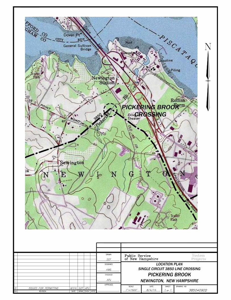
1. The design and proposed construction of these crossings is shown on the attached PSNH Transmission Business Drawings entitled “SINGLE CKT F107 BETWEEN STR. 119 & 120 PICKERING BROOK, NEWINGTON, NEW HAMPSHIRE” (Drawing No. F10740903) marked as Exhibit 3 and “SINGLE CKT 3850 BETWEEN STR. 5 & 6 PICKERING BROOK, NEWINGTON, NEW HAMPSHIRE” (Drawing No. 385040901) marked as Exhibit 5.
2. The location of the single circuit F107 crossing is shown on the attached
Location Plan marked as Exhibit 4. The location of the single circuit 3850 crossing is shown on the attached Location Plan marked as Exhibit 6.
3. Line F107 will cross the Pickering Brook on a 1-pole, direct embed, 100 foot pole (16 feet embedded), steel tangent suspension structure (eastern side) and on a 1-pole, 75 foot, steel deadend strain structure on concrete foundation (western side). Details of these structures are shown on Exhibit 3. As shown on Exhibit 3, for Structure 120 the 115kV phase wires have an approximate separation at the structure of 8 -15 feet vertically and 0-13 feet horizontally (6.5 foot post insulators) in a delta configuration. The static wire is carried on the structure by a support bracket approximately nine inches down from the top of the structure. As shown on Exhibit 3, for Structure 119 the 115kV phase wires have an approximate separation at the structure of 7 -15 feet vertically and 2.5-20 feet horizontally in a delta configuration. The static wire is carried on the structure by a support bracket approximately six inches down from the top of the structure. Land along the shoreline between the structures of this crossing and the river is not traversable by vehicles. However, minimum distances to ground per the NESC have been met. A clearance of 26.2 feet between the phase wire and the closest ground point has been provided. This exceeds the NESC required clearance of 20.1 feet by 6.1 feet. As all other phase wires are above this elevation they will always exceed the NESC required clearance.
4. Line 3850 will cross the Pickering Brook on a 1-pole, direct embed, 60 foot pole (eight feet embedded), wood deadend structure (western side) and on a 1-pole, direct embed 60 foot (eight feet embedded), wood tangent structure (eastern side). As shown on Exhibit 5, for Structure 5 the 34.5kV phase wires have an approximate separation at the structure of five feet vertically and 0-9 feet horizontally in a horizontal configuration. The neutral wire is carried on the structure by a support bracket approximately five feet down below the 34.5kV phase wires. As shown on Exhibit 5, for Structure 6 the 34.5kV phase wires have an approximate separation at the structure of four feet eight inches horizontally in a horizontal configuration. The neutral wire is carried on the structure by a support bracket approximately five feet down below the
11
34.5kV phase wires. All NESC clearances at the structure as described in paragraph 11 of the petition have been met by exceeding the horizontal and/or vertical clearances required. Land along the shoreline between the structures of this crossing and the river is not traversable by vehicles. However, minimum distances to ground per the NESC have been met. A clearance of 21 feet between the neutral and the closest ground point has been provided. This exceeds the NESC required clearance of 15.5 feet by 5.5 feet. As all other phase wires are above this elevation they will always exceed the NESC required clearance.
5. Flood water elevations for the Pickering Brook were based on information contained in flood insurance rate maps provided by FEMA. There was no flood elevation provided on the FEMA Maps as this portion of Pickering Brook is in the Zone X section of Map 33015C0255E, dated May 17, 2005. Zone X locations indicate that under a 100 year flood event the flood depth would be less than 1 foot. For conservative design it was assumed that the water level would not exceed the top of bank during a 10 year flood. The 10-year flood elevation for this portion of the river was designed at approximately 27.7 feet. This far exceeds the 1 foot depth prescribed on the FEMA flood map. The area of the crossing, as required by the NESC (Section 232), is approximately 9.9 acres (82 feet x5280 feet/43560sf/acre). As stated in paragraph 10 of the petition, the minimum required 115 kV conductor clearance for water surface areas between under 20 acres is 22.1 feet for 115 kV and 20.5 feet for 34.5 kV. 6. The sags and clearances to the water surface during a 10-year flood event for this crossing are as follows;
• PSNH has investigated a multitude of weather and loading conditions for its design. PSNH used these design conditions and combinations thereof to determine the minimum clearance of all conductors to the water and land surfaces, between the phase conductors and OPGW cable and neutral conductors. PSNH has determined that the weather cases and combinations listed below results in the minimum clearance and control over all other weather conditions and combinations.
• Shield wires – Due to the fact that the OPGW wire is located above the phase wires, its clearance to the water surface will always exceed the minimum required NESC distance.
• F107 (115 kV): 285 degrees F – Max operating temperature (Phase
wires) based on PSNH transmission standards - The maximum conductor sag for this weather case will be 18.4 feet with a clearance to the water surface of 34.1 feet. This condition produces the greatest sag in the phase wires and therefore the minimum clearance to the water surface. This design will exceed the minimum clearance requirement of 22.1 feet by 12 feet under temporary emergency conditions during a 10-yr storm event.
12
• F107 (115 kV): Minimum phase to shield wire(s) clearance – The weather case that would produce the minimum clearance between the phase wires and the shield wires would be a combination of winter weather factors. First, the phase wires would have to be at 30 deg. F just after an ice storm and would have just dropped their ice. The shield wires would be at 32 deg. F and would still be iced with 1/2” of radial ice. Under these conditions the clearance would be 13.5 feet vertically and 6 feet horizontally from the shield wires to the closest phase wire. As described in Paragraph 11 of the petition 64.7 inches (5.4 feet) of horizontal and/or 32.3 inches (2.7 feet) of vertical clearance is required between 115kV and 0kV conductors. The line would exceed both clearance requirements.
• 380 (34.5 kV): 212 degrees F – Max operating temperature (Phase
wires) based on PSNH distribution standards - The maximum conductor sag for this weather case will be 22.1 feet with a clearance to the water surface of 31.9 feet. This condition produces the greatest sag in the phase wires and therefore the minimum clearance to the water surface. This design will exceed the minimum clearance requirement of 20.5 feet by 11.4 feet under temporary emergency conditions during a 10-yr storm event.
• 380 (Neutral): 120 degrees F – Max operating temperature (Phase
wires) based on PSNH distribution standards - The maximum conductor sag for this weather case will be 19 feet with a clearance to the water surface of 23.5 feet. This condition produces the greatest sag in the phase wires and therefore the minimum clearance to the water surface. This design will exceed the minimum clearance requirement of 17.5 feet by 6 feet under temporary emergency conditions during a 10-yr storm event.
• 380 (Neutral): Minimum phase to neutral clearance – The weather
case that would produce the minimum clearance between the 34.5kV phase wires and the neutral wire would be a condition where the neutral conductor is at 80 deg. F and the 34.5kV conductors are at their maximum operating temperatures of 212 degrees F. Under these conditions the clearance of the closest 34.5kV line would be 2.4 feet vertically and 0 feet horizontally from the neutral wire to the closest phase wire. As described in Paragraph 11 of the petition, 49.8 inches (4.15 feet) of horizontal and/or 15.7 inches (1.3 feet) of vertical clearance is required between 34.5kV and 0kV conductors. The line design will meet these requirements as the conductors will exceed the vertical requirement by 1.1 feet under worst case conditions.
13
APPENDIX C
F107 Line Little Bay
Durham, NH and Newington, NH
1. The design and proposed construction of this crossing is shown on the attached PSNH Transmission Business Drawing entitled “F107 LINE CROSSING, LITTLE BAY DURHAM AND NEWINGTON, NEW HAMPSHIRE” (Drawing No. F10740905) marked as Exhibit 7.
2. The location of the F107 crossing of Little Bay is also shown on Exhibit 7. 3. Line F107 will cross Little Bay using three underground submarine cables.
The three cables will be buried using a water jet plow, driver hand jetting or mechanical trenching. The submarine cable will begin at F107 Structure 101 on the West shore of Little Bay. This structure will be a single pole, 80 foot, steel deadend strain structure on concrete foundation. The cable will then run underwater to an underground manhole on the East shore of Little Bay. Details of Structure 101 are provided with the petition on Exhibit 7. As shown on Exhibit 7, for Structure 101 the overhead 115kV phase wires have an approximate separation at the structure of 6 to 12 feet vertically and 0 to 20 feet horizontally in a delta configuration. The static wire is carried on the structure by a support bracket approximately 9 inches down from the top of the structure on the left and right poles. The submarine cable will run down the pole at Structure 101 and be buried to a depth of 42 inches heading east for approximately 367 feet by open trenching or diver burial, one phase per pole, from the overhead conductor elevation. The cables will then proceed 1835 feet at 42 inch burial using a water jet plow. At that point the depth will be increased to 8 feet depth in the main channel for approximately 2431 feet. Continuing the Eastern path, the depth will decrease to 42 inches for the last 770 feet where the cable will come on shore and enter an underground splice vault. From that point the submarine cable will be spliced to a land based underground cable to connect to the above ground portion of the line at Structure 102. Details of the splice vault have been included on Exhibit 7. As shown on Exhibit 7 the cables will be installed 42 inches below finished grade and will be spaced a minimum of 18 inches apart vertically attached to the side of the manhole. All NESC clearances at the structure, as described in paragraph 11 of the petition, have been met by exceeding the horizontal and/or vertical clearances required. This crossing will be entirely underground or underwater so all overhead clearances described will not be applicable to this crossing.
4. The underwater crossing will consist of three 115kV rated, 1400 mm2
XLPE submarine cables. The cable will have a copper wire core surrounded by extruded XLPE insulation. A layer of copper armoring will be installed on the outside of the cable to provide mechanical protection. The overall cable diameter will be approximately 140.2 mm. The cables will be installed with a separation of approximately 30 feet in the main channel of Little Bay. As they approach land the will converge to within 5 feet separation. Two ADSS fiber optic cables will be strapped to two separate cable (one
14
ADSS cable per conductor cable) to continue the fiber optic path for the F107 line. These cables will follow the same route as the 115kV conductors. There are four existing cables in the corridor that have been abandoned. Some of these cables may be raised to the surface, cut, capped and reset on the bottom to move them out of the way of the new cable installation.
5. The submarine cable will be buried between 42 inches and 96 inches depending on the location within the Little Bay. This will meet or exceed the NESC clearance of 42 inches based on Table 352-1 of the NESC for underground direct bury cable over 50kV. Section 351.C.5 of the NESC also states that “Submarine crossings should be routed, installed, or both, so they will be protected from erosion by tidal action or currents. They should not be located where ships normally anchor.” All three cables will be located in an existing cable crossing location as shown on the NOAA Navigational Chart for Little Bay and Great Bay attached to this petition as Exhibit 8. Per the NOAA Nautical Chart User’s Manual dated 1997 this designation includes restrictions on anchoring in the cable area. This satisfies the requirement of the NESC. The cables will also be buried to protect them from tidal action as well as any inadvertent boat anchors.
6. The underground vault will comply with all requirements of the NESC.
As described in NESC Section 323.A, the underground vault will be designed for an HS-20 vehicle loading. Per NESC Section 323.B, the underground vault will have a vertical dimension not less than 6 feet and a minimum of 3 feet of working space and shall be accessible by two manholes with a minimum diameter of 26 inches.
GRAPHIC SCALE
GRAPHIC SCALE
GRAPHIC SCALE
Feet
1:6000
10005000
250
PLAN VIEW
PROFILE VIEW
CaldwellMarine International, LLC.
LOCUS
EXHIBIT 8
LOCATION OF CHARTED CABLE AREA.APPROXIMATELY 1000 FEET WIDE
1
THE STATE OF NEW HAMPSHIRE BEFORE THE
PUBLIC UTILITIES COMMISSION
PETITION OF PUBLIC SERVICE COMPANY OF NEW HAMPSHIRE D/B/A EVERSOURCE ENERGY FOR LICENSES TO CONSTRUCT AND MAINTAIN ELECTRIC LINES, NEUTRAL WIRE AND FIBER OPTIC CABLE OVER AND ACROSS PUBLIC LANDS OWNED BY THE STATE OF NEW HAMPSHIRE IN THE TOWNS OF DURHAM AND NEWINGTON, NEW HAMPSHIRE TO THE PUBLIC UTILITIES COMMISSION: Public Service Company of New Hampshire d/b/a Eversource Energy (“PSNH”), a public utility engaged in the generation, transmission, distribution and sale of electricity in the State of New Hampshire, hereby petitions the Public Utilities Commission (“Commission”), pursuant to RSA 371:17, for licenses to construct and maintain electric lines, neutral wire and fiber optic cable at five locations over and across public lands owned by the State of New Hampshire in the Towns of Durham and Newington, New Hampshire, and in support of its petition states as follows: 1. In order to meet the reasonable requirements of service to the public, PSNH has previously constructed and currently operates and maintains three 34.5 kV lines in the New Hampshire Seacoast Region, designated as Lines 380, 3162 and 3850. Line 380 runs between PSNH’s Madbury Substation in Madbury, New Hampshire to PSNH’s Packers Falls Substation in Durham, New Hampshire. Line 3162 runs from PSNH’s Packers Falls Substation to Little Bay in Durham, New Hampshire. Line 3850 runs from PSNH’s Portsmouth Substation in Portsmouth, New Hampshire to Little Bay in Newington, New Hampshire. Lines 380, 3162 and 3850 are an integral part of the PSNH distribution system serving the New Hampshire Seacoast Region.
2. In order to continue to meet the reasonable requirements of service to the public, PSNH has determined it is necessary to install a new 115kV line from the Madbury Substation in Madbury, New Hampshire to the Portsmouth Substation in Portsmouth, New Hampshire, to be designated as Line “F107”, also identified as PSNH’s Seacoast Reliability Project. Line F107 is needed to provide a parallel path to enhance the existing 115 kV loop between the Deerfield and Scobie Pond Substations in order to address reliability concerns in the New Hampshire Seacoast Region, which have previously been identified by the Independent System Operator – New England (“ISO-NE”). PSNH, working with ISO-NE, conducted a needs assessment study which concluded that the New Hampshire Seacoast Region requires additional transmission capacity to support the reliable delivery of electric power to meet the region’s current demand and future increased demand. The approximate in-service date for this new line is in the 4th Quarter of 2018. Installing this new transmission line will allow PSNH to continue to provide reliable electric service to its customers in this area of the State.
2
3. The F107, as presently proposed, includes overhead crossings of properties now owned by the State of New Hampshire (hereinafter referred to as the “public lands” or “public land”) at three (3) locations in the Town of Durham and at two (2) locations in the Town of Newington. The general location plans of these crossings have been provided on Exhibits 1, 4, 6 and 8 of this petition.
4. In Durham, the first two locations are lands maintained by The New
Hampshire Fish and Game Department (NHF&G) located just north of Bennett Road and west of NH Route 108 (see Exhibit 1). The third crossing location is also maintained by NHF&G and is located east of Sandy Brook Drive and north of Long Marsh Road (see Exhibit 4). The first overhead crossing involves the F107, 380 and 3162 Line spans, between Structures 46 and 58, which cross the public land located north of Bennett Road. This crossing also includes placement of Structures 47 through 57 on this public land. The second overhead crossing involves the F107 and 3162 Line spans, between Structures 59 and 61, which cross the public land located west of New Hampshire Route 108. This crossing also includes placement of Structure 60 on this public land. The third overhead crossing involves the F107and 3162 Line spans, between Structures 74 and 80, which cross the public land located east of Sandy Brook Drive. This crossing also includes placement of Structures 75 through 79 on this public land.1
5. In Newington, the overhead crossings are on two parcels maintained by
The New Hampshire Department of Transportation (NHDOT), both located west of the Spaulding Turnpike (see Exhibits 6 and 8). The first overhead crossing involves the F107 and 3850 Line spans, between F107 Structures 123 and 129, and between 3850 Structures 9 and 15, which cross public land located west of the Spaulding Turnpike. This crossing also includes placement of F107 Structures 124 through 128, and placement of 3850 Structures 10 through 15, on this public land2. The second overhead crossing involves the F107 Line spans, between F107 Structures 131 and 133, which cross other public land also located west of the Spaulding Turnpike. This crossing also includes placement of F107 Structure 132 on this public land. 6. In order to improve and enhance the reliability and capacity of the communications system used in its electric system operations, and thereby meet the reasonable requirements of service to the public, PSNH will also install and maintain an optical ground wire, known as OPGW cable, on its new overhead line structures, which will cross the same public lands at the same locations as the electric overhead crossings. In addition to communications capabilities, the OPGW will provide lightning protection over the conductors in the overhead configurations. 1 Due to either oversight, or the fact that the lands involved were in private ownership at the time of original construction, neither the existing 380 Line crossing, nor the existing 3162 Line crossings of these public lands have been previously licensed by the Commission; however, each of these crossings will be licensed under this petition. 2 Due to either oversight, or the fact that the lands involved were in private ownership at the time of original construction, the existing 3850 Line crossings of these public lands have not been previously licensed by the Commission; however, these crossings will be licensed under this petition.
3
7. At the overhead crossings of the existing 380 and 3162 Line in Durham, the existing pole structures will be replaced with new double circuit single pole or multi-pole structures designed to handle the loads of supporting both the 115 kV F107 and either the 34.5 kV 380 or 3162 Lines. At the overhead crossings of the existing 3850 Line in Newington, the existing pole structures will be replaced with separate single circuit, single pole structures each designed to handle the loads of supporting the 115 kV F107 Line and the 34.5 kV 3850 Line, respectively. The F107 Line overhead crossings will be built with 1590 kcmil ACSR 45/7 conductor, and the 380 line, 3162 Line and 3850 crossings will be built with 477 kcmil ACSR 18/1 conductor. The 380 line has also been designed to accommodate 795 ACSR 26/7 conductor, with no change in clearances, which may be required based on anticipated future needs that may coincide with the timing of this project. A portion on the 3162 Line near New Hampshire Route 108 in Durham will be constructed with 477 kcmil spacer cable attached to a 19#10 alumoweld messenger cable. As noted above, F107 will support an optical ground wire (OPGW) for its entirety. 8. The general location of the F107, 380, 3162 and 3850 Line crossings that are the subject of this petition are attached as Exhibit 1 to Appendix A and Appendix B, Exhibit 4 to Appendix C, Exhibit 6 to Appendix D, and Exhibit 8 to Appendix E of this petition, respectively. 9. The clearance of conductors to public lands for each of the proposed crossings are provided on the plan and profile drawings attached as Exhibit 2 and 3 to Appendix A, as Exhibit 3 to Appendix B, as Exhibit 5 to Appendix C, as Exhibit 7 and 10 to Appendix D, and as Exhibit 9 to Appendix E of this petition, respectively. 10. The required technical information provided in this petition is based on the 2012 National Electrical Safety Code (NESC) C2-2012. The proposed crossings have been designed and will be constructed, maintained and operated by PSNH in accordance with the applicable requirements of the NESC. 11. Each of the crossings will be spanned using steel structures. Single wood or steel poles will be used at some locations as extra support for the 34.5kV conductors. Detail designs of these crossings and structure details have been outlined in Appendices A, B, C, D and E. The detailed configurations for all crossing structures are shown on Exhibit 11 of this petition.
12. Based on Table 232-1 of the NESC, for areas subject to truck traffic, neutral conductors 0V to 300V shall have a clearance to ground of 15.5 feet, and open supply conductors 750 V to 22 kV, shall have a minimum clearance to 18.5 feet. With an additional 1.6 feet of clearance required for 115 kV, the total required ground clearance for 115kV is 20.1 feet.
4
13. Based on Table 235-13 of the NESC for horizontal clearance at the supports for wires or conductors carried on the same supporting structure, 57.4 inches is required between 115kV conductors, 22.9 inches is required between 34.5kV conductors, 45.3 inches is required between 115kV and 34.5kV conductors, 36.9 inches are required between 115kV and 0kV neutral or static wires and 16.9 inches are required between 34.5kV and 0kV neutral or static wires. Based on Table 235-3 of the NESC for horizontal clearance along the span for wires or conductors carried on the same support 80.1 inches is required between 115kV conductors, 54.2 inches between 34.5kV conductors, 64.7 inches are required between 115kV and 0kV neutral or static wires, 49.8 inches are required between 34.5kV and 0kV neutral or static wires and 70.7 inches are required between 115kV and 34.5kV conductors. These horizontal clearances assume conductor or wire sag of 30 feet (360 inches) which exceeds any sag at the location of these crossings. Based on Table 235.5 of the NESC, the vertical clearance required at the supports for wires or conductors carried on the same supporting structure is 60.9 inches between 115kV conductors, 26.9 inches between 34.5kV conductors, 48.8 inches between 115kV and 34.5kV conductors, 40.4 inches are required between 115kV and 0kV neutral or static wires and 20.9 inches are required between 34.5kV and 0kV neutral or static wires. Based on Rule 235.C.b.1 of the NESC, the vertical clearance required in the span for wires or conductors carried on the same supporting structure is 52.8 inches between 115kV conductors, 20.2 inches between 34.5kV conductors, 40.7 inches between 115kV and 34.5kV conductors, 32.3 inches are required between 115kV and 0kV neutral or static wires and 15.7 inches are required between 34.5kV and 0kV neutral or static wires. Per Figure 235-1 of the NESC, conductors or wires cannot encroach the envelope formed by the horizontal and vertical clearances prescribed above.
14. A total of three phase wires and one OPGW cable will span the overhead public land crossings for F107. A total of three phase wires and one neutral wire will span the overhead public land crossings for the 380, 3162 and 3850 Lines. In some locations, spacer cable rated for 34.5kV will be installed as an alternative to open wire conductors due to right of way space constraints. This spacer cable will be 477 kcmil cable. All three 1590 kcmil ACSR 45/7 phase conductors, all three 477 kcmil ACSR 18/1 phase conductors phase conductors, shield wire, messenger cables and the neutral wire will be sagged using the NESC Heavy Loading (0 degrees F, 4 pounds per square foot wind loading, ½-inch radial ice) sag charts upon installation in the field. The 1590 kcmil ACSR 45/7 conductors will be sagged using a maximum tension of 11,400 pounds (unless stated otherwise), the 477 kcmil ACSR 18/1 conductors will be sagged using a maximum tension of 3,500 pounds (unless stated otherwise), the shield wire will be sagged using a maximum tension of approximately 4,500 pounds, the messenger cable used to support the spacer cable will be sagged using a maximum tension of 9,000 pounds and the neutral wire will be sagged using a maximum tension of 2,500 pounds. The 477 kcmil spacer cable hangs on the messenger cable using support brackets with slack tensions. The sags and clearances to the land surface for each of the proposed overhead crossings are provided in the attached Appendices A, B, C, D and E. 3 Table 235-1 of the NESC does not specify a horizontal clearance value for conductors of the same circuit above 50kV phase to phase. The values provided are based on values for supply conductors of a different circuit.
5
15. A wetlands permit from the New Hampshire Department of Environmental Services (NHDES) and the U.S. Army Corp or Engineers (USACE) is required for the installation of Structures 48 and Hen1 (see Appendix A), and Hen3 and Hen4 (see Appendix B), and for access during construction. The appropriate wetlands permits will be applied for and obtained by PSNH prior to the installation of any new structures in wetlands, in conjunction with PSNH’s Seacoast Reliability Project siting application for the F107 Line. The F107 crossings are subject to approval and the issuance of a certificate of site and facility by the New Hampshire Site Evaluation Committee (NHSEC) as part of PSNH’s Seacoast Reliability Project filing. All approvals as part of that process will be obtained prior to construction.
16. For all of the overhead crossings which are the subject of this petition, PSNH owns a permanent, minimum 100 foot wide easement or a 100 foot wide use and occupancy utility corridor for its lines and facilities on the public lands of the proposed crossing locations. Each of the overhead crossings will be constructed within the limits of those easements and corridors.
17. Aerial crossings of NH Route 108 are required as part of the crossing between
structures 59 and 61 described in Appendix B of this petition. The appropriate NHDOT permission agreements will be applied for and obtained by PSNH prior to the installation of any new structure that will impact NHDOT jurisdictional areas, in conjunction with PSNH’s Seacoast Reliability Project siting application.
18. All Seacoast Reliability Project structures in Newington, including all those
proposed for the public land crossings which are the subject of this petition, will need an air obstruction determination from the Federal Aviation Administration (FAA) under Federal Aviation Regulation Part 77.9(b), due to proximity to the Portsmouth International Airport at Pease. Determinations will be requested from the FAA and appropriate measures will be taken by PSNH prior to the installation of any new structures that will impact FAA jurisdictional areas. 19. PSNH submits that the licenses petitioned for herein may be exercised without substantially affecting the rights of the public in the public lands covered in this petition. Minimum safe line clearances above all surfaces will be maintained at all times. The use and enjoyment by the public of the public lands will not be diminished in any material respect as a result of the overhead lines. WHEREFORE, PSNH respectfully requests that the Commission:
a. Find that the licenses petitioned for herein may be exercised without substantially affecting the public rights in the public lands of the State of New Hampshire which are the subject of this petition;
6
b. Grant PSNH licenses to construct and maintain electric lines, neutral wire and fiber optic cable over and across the public lands of the State of New Hampshire as specified in the petition;
c. Issue an Order Nisi and orders for its publication; and,
d. Grant such other and further relief as may be just and reasonable. Dated at Manchester this 9th day of March, 2016.
Respectfully submitted, PUBLIC SERVICE COMPANY OF NEW
HAMPSHIRE d/b/a EVERSOURCE ENERGY
__________________________________ Christopher J. Allwarden Senior Counsel, Legal Department Eversource Energy Service Company 780 North Commercial Street Manchester, NH 03101 (603) 634-2459
7
APPENDIX A
F107 & 380 & 3162 Lines Spans 46-58
State of New Hampshire-Fish and Game Department DURHAM, NH
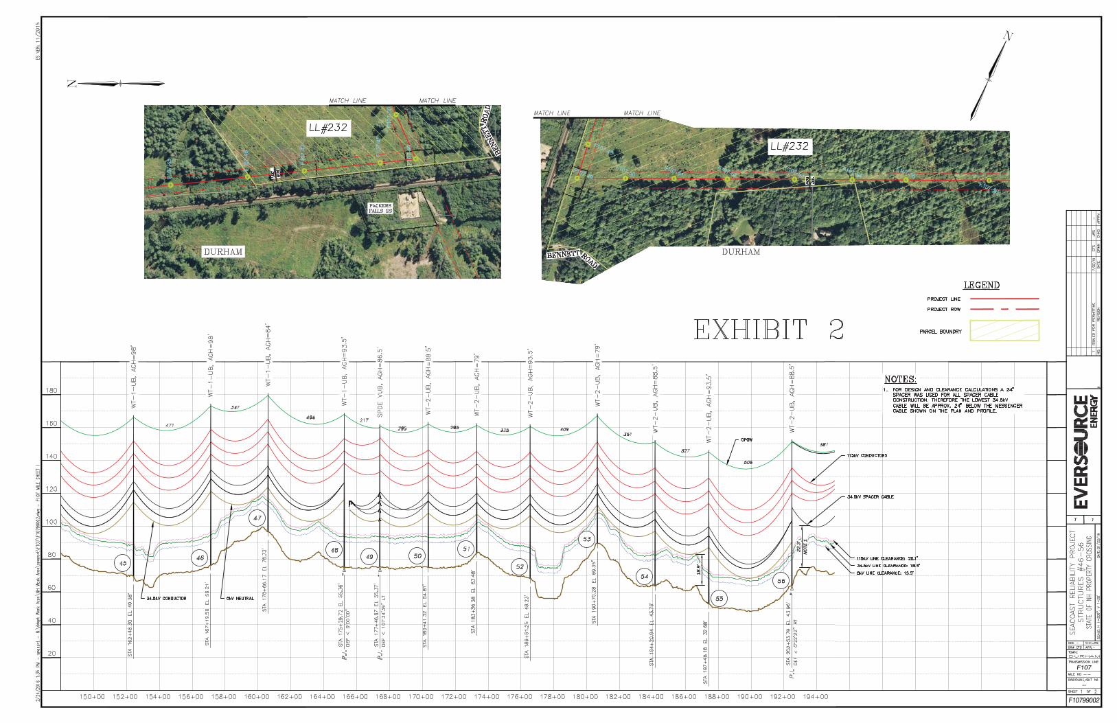
1. The design and proposed construction of this crossing is shown on the
attached Eversource Energy Drawings entitled “Seacoast Reliability Project Structures #46-56, State of NH Property Crossing” (Drawing No. F10799002 Sheet 1 of 2) and “Seacoast Reliability Project Structures #56-61, State of NH Property Crossing” (Drawing No. F10799002 Sheet 2 of 2) marked as Exhibit 2 and Exhibit 3, respectively.
2. The location of this crossing is shown on the attached Location Plan
marked as Exhibit 1.
3. Lines F107, 380 and 3162 will cross the public land north of Bennett Road primarily on 1-pole, direct embed, steel tangent suspension structures designated as Type WT-1-UB, and on a direct embed, steel tangent suspension structures designated as Type WT-2-UB. Structure 49 is a 1-pole, steel dead-end structure on a concrete foundation designated as Type SPDE-VUB. Structures 57 and 58 are two-pole, direct embed tangent structures designated as Type RAX-UB. Details of these structures are shown on Exhibit 11. Above ground structure heights (AGH) for each of the crossing structures is shown on Exhibits 2 and 3.
• As shown on Exhibit 11, for the Type WT-1-UB structures the 115kV phase wires have an approximate separation at the structure of 7.5 -15 feet vertically and 0-13 feet horizontally in a delta configuration. The static wire is carried on the structure by a support bracket approximately nine inches down from the top of the structure. The 34.5kV phase wires are arranged horizontally approximately 15 feet below the lowest 115kV conductor and have an approximate separation at the structure of 0-5 feet vertically and 2.5-6 feet horizontally. The neutral wire is carried on the structure by a support bracket approximately 7.5 feet down below the 34.5kV phase wires.
• As shown on Exhibit 11, for the Type WT-2-UB structures the 115kV phase wires have an approximate separation at the structure of 7.5 -15.5 feet vertically and 0-13 feet horizontally in a delta configuration. The static wire is carried on the structure by a support bracket approximately nine inches down from the top of the structure. The 34.5kV phase wires are arranged horizontally approximately 15.5 feet below the lowest 115kV conductor and have an approximate separation at the structure of 0-2.5 feet vertically and 2.5-6 feet horizontally. The neutral wire is carried on the structure by a support bracket approximately seven feet down below the 34.5kV phase wires.
8
• As shown on Exhibit 11, for the Type SPDE-VUB structures the 115kV phase wires have an approximate separation at the structure of ten feet vertically and zero feet horizontally in a vertical configuration. The static wire is carried on the structure by a support bracket approximately six inches down from the top of the structure. The 34.5kV phase wires are arranged vertically approximately 13 feet below the lowest 115kV conductor and have an approximate separation at the structure of 5 feet vertically and 0 feet horizontally. The neutral wire is carried on the structure by a support bracket approximately six feet down below the 34.5kV phase wires.
• As shown on Exhibit 11, for the Type RAX-UB structures the 115kV phase wires have an approximate separation at the structure of zero feet vertically and 14 feet horizontally in a horizontal configuration. The static wire is carried on the structure by a support bracket approximately nine inches down from the top of the structure. The 34.5kV phase wires are arranged on a bracket in a spacer cable bundle approximately 15 feet below the lowest 115kV conductor and have an approximate separation of 24 inches within the bundle. The neutral wire is carried as the messenger portion of the spacer cable bundle. Structures marked as “Hen” are single wood pole structures used to support the 34.5kV spacer cable on long spans. Only the 34.5kV cables and messenger are attached to the pole on a support bracket located approximately 6 inches from the top of the pole. All NESC clearances at the structure as described in paragraphs 12 and 13of the petition have been met by exceeding the horizontal and/or vertical clearances required.
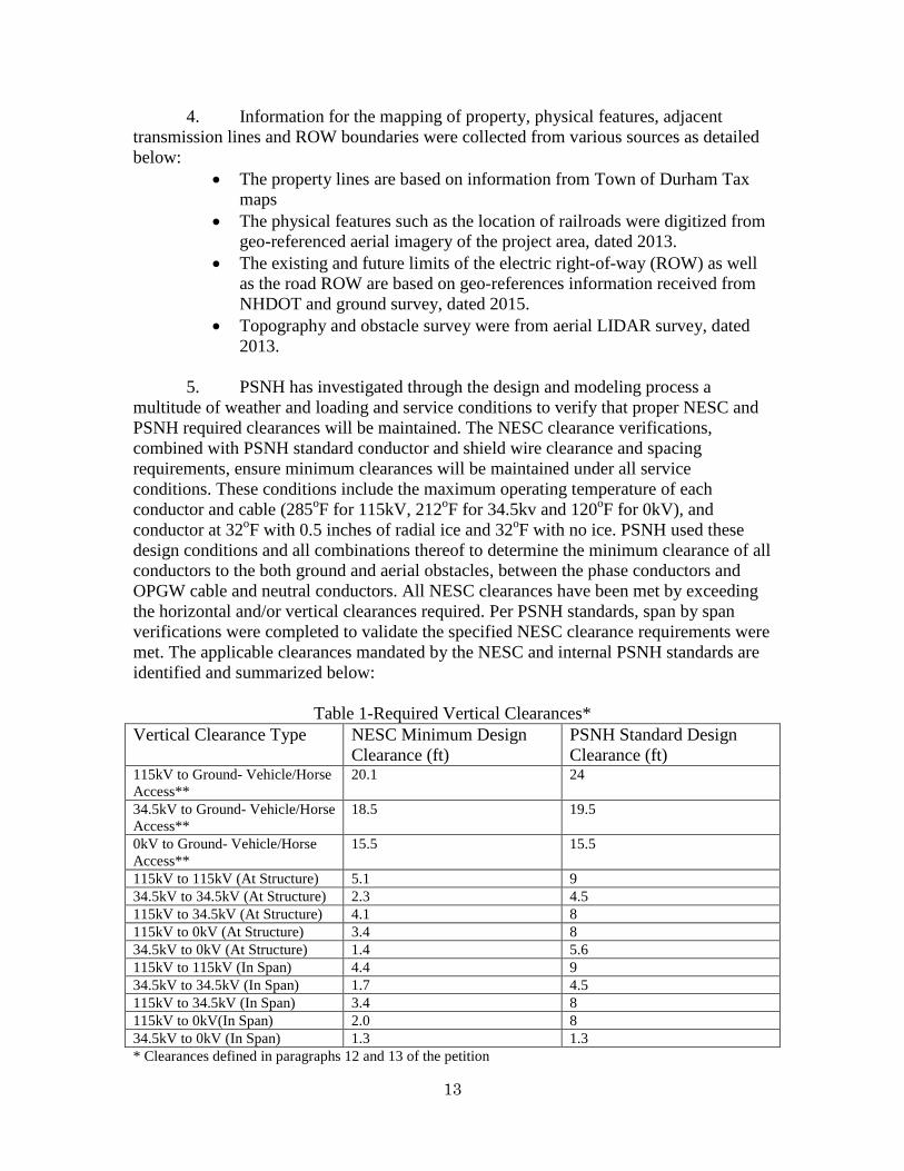
4. Information for the mapping of property, physical features, adjacent
transmission lines and ROW boundaries were collected from various sources as detailed below:
• The property lines are based on information from Town of Durham Tax maps
• The physical features such as the location of railroads were digitized from geo-referenced aerial imagery of the project area, dated 2013.
• The existing and future limits of the electric right-of-way (ROW) as well as the road ROW are based on geo-references information received from NHDOT and ground survey, dated 2015.
• Topography and obstacle survey were from aerial LIDAR survey, dated 2013.
5. PSNH has, through the design and modeling process, investigated a multitude of weather and loading and service conditions to verify that proper NESC and PSNH required clearances will be maintained. The NESC clearance verifications, combined with PSNH standard conductor and shield wire clearance and spacing requirements, ensure minimum clearances will be maintained under all service conditions. These conditions include the maximum operating temperature of each conductor and cable (285oF for 115kV, 212oF for 34.5kv and 120oF for 0kV), and conductor at 32oF with 0.5 inches of radial ice and 32oF with no ice. PSNH used these
9
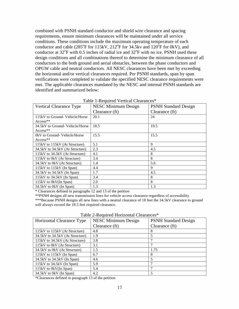
design conditions and all combinations thereof to determine the minimum clearance of all conductors to the both ground and aerial obstacles, between the phase conductors and OPGW cable and neutral conductors. All NESC clearances have been met by exceeding the horizontal and/or vertical clearances required. Per PSNH standards, span by span verifications were completed to validate the specified NESC clearance requirements were met. The applicable clearances mandated by the NESC and internal PSNH standards are identified and summarized below:
Table 1-Required Vertical Clearances* Vertical Clearance Type NESC Minimum Design
Clearance (ft) PSNH Standard Design Clearance (ft)
115kV to Ground- Vehicle/Horse Access**
20.1 24
34.5kV to Ground- Vehicle/Horse Access**
18.5 19.5
0kV to Ground- Vehicle/Horse Access**
15.5 15.5
115kV to 115kV (At Structure) 5.1 9 34.5kV to 34.5kV (At Structure) 2.3 4.5 115kV to 34.5kV (At Structure) 4.1 8 115kV to 0kV (At Structure) 3.4 8 34.5kV to 0kV (At Structure) 1.4 5.6 115kV to 115kV (In Span) 4.4 9 34.5kV to 34.5kV (In Span) 1.7 4.5 115kV to 34.5kV (In Span) 3.4 8 115kV to 0kV(In Span) 2.0 8 34.5kV to 0kV (In Span) 1.3 1.3 * Clearances defined in paragraphs 12 and 13 of the petition **PSNH designs all new transmission lines for vehicle access clearance regardless of accessibility ***Because PSNH designs all new lines with a neutral clearance of 18 feet the 34.5kV clearance to ground will always exceed the 18.5 feet required clearance.
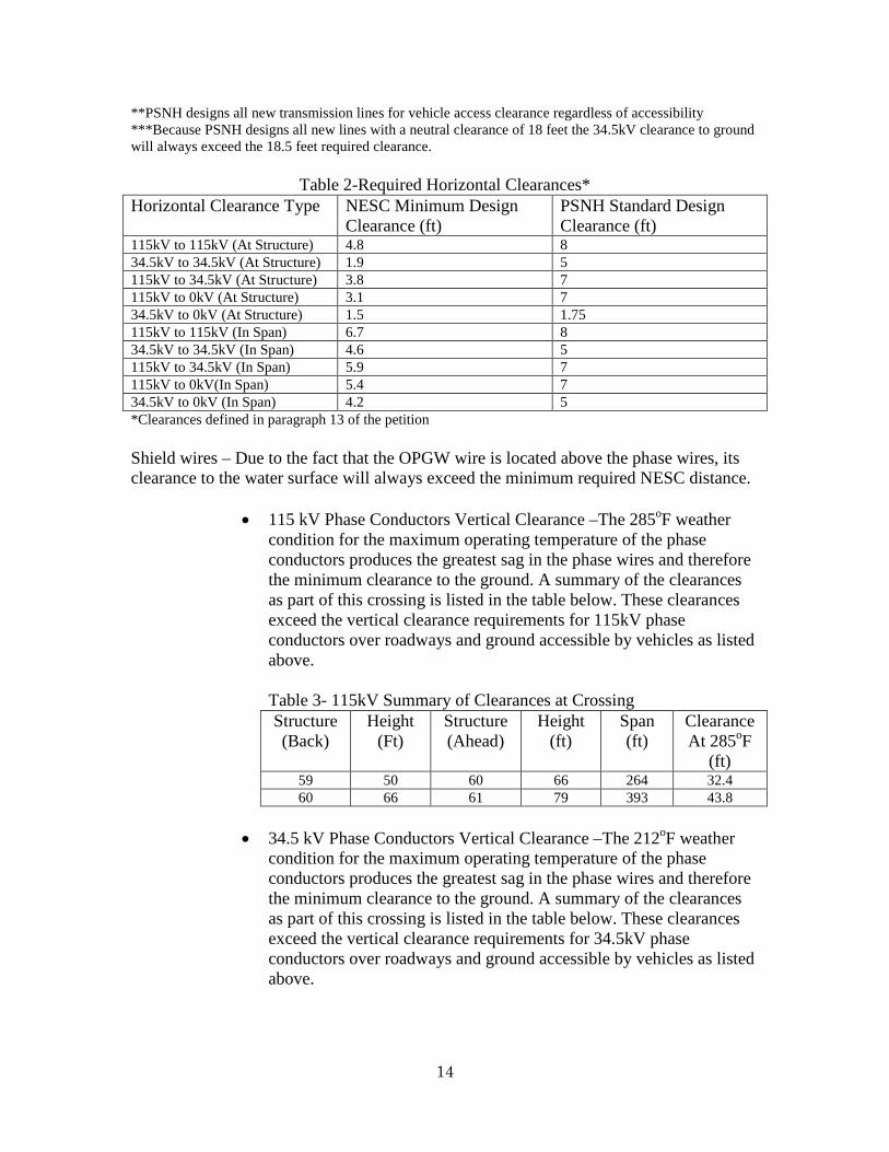
Table 2-Required Horizontal Clearances* Horizontal Clearance Type NESC Minimum Design
Clearance (ft) PSNH Standard Design Clearance (ft)
115kV to 115kV (At Structure) 4.8 8 34.5kV to 34.5kV (At Structure) 1.9 5 115kV to 34.5kV (At Structure) 3.8 7 115kV to 0kV (At Structure) 3.1 7 34.5kV to 0kV (At Structure) 1.5 1.75 115kV to 115kV (In Span) 6.7 8 34.5kV to 34.5kV (In Span) 4.6 5 115kV to 34.5kV (In Span) 5.9 7 115kV to 0kV(In Span) 5.4 7 34.5kV to 0kV (In Span) 4.2 5 *Clearances defined in paragraph 13 of the petition Shield wires – Due to the fact that the OPGW wire is located above the phase wires, its clearance to the water surface will always exceed the minimum required NESC distance.
10
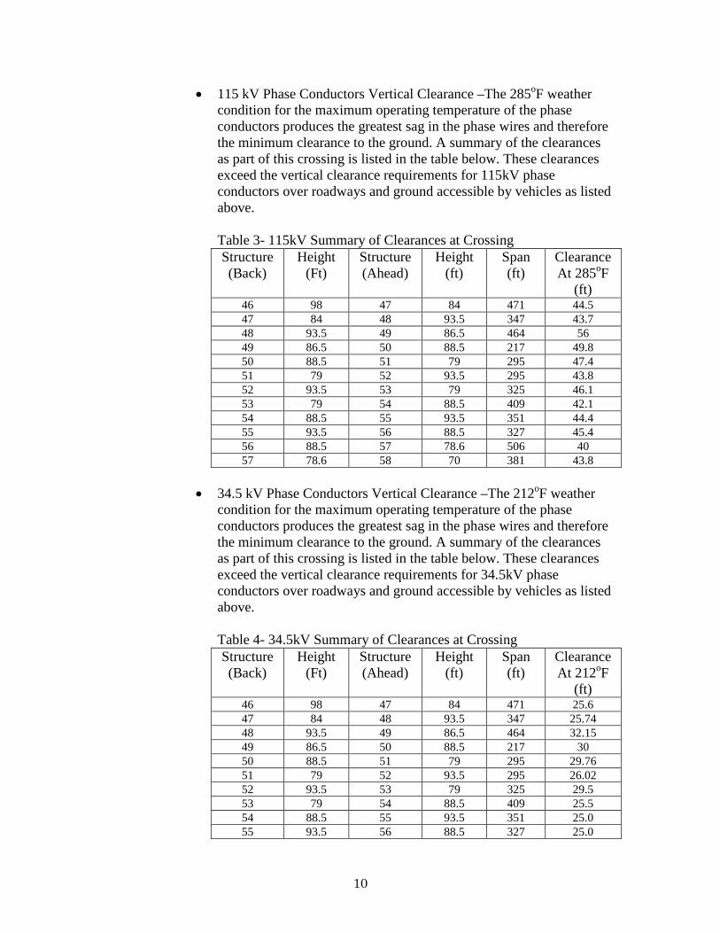
• 115 kV Phase Conductors Vertical Clearance –The 285oF weather condition for the maximum operating temperature of the phase conductors produces the greatest sag in the phase wires and therefore the minimum clearance to the ground. A summary of the clearances as part of this crossing is listed in the table below. These clearances exceed the vertical clearance requirements for 115kV phase conductors over roadways and ground accessible by vehicles as listed above. Table 3- 115kV Summary of Clearances at Crossing Structure (Back)
condition for the maximum operating temperature of the phase conductors produces the greatest sag in the phase wires and therefore the minimum clearance to the ground. A summary of the clearances as part of this crossing is listed in the table below. These clearances exceed the vertical clearance requirements for 34.5kV phase conductors over roadways and ground accessible by vehicles as listed above. Table 4- 34.5kV Summary of Clearances at Crossing Structure (Back)
• 0 kV Neutral- For the neutral conductors the 120oF weather condition
for the maximum operating temperature of the phase conductors produces the greatest sag in the phase wires and therefore the minimum clearance to the ground. A summary of the clearances as part of this crossing is listed in the table below. These clearances exceed the vertical clearance requirements for 0kV neutral conductors over roadways and ground accessible by vehicles as listed above. Table 5- 0kV Summary of Clearances at Crossing Structure (Back)
• Conductors and Cables Horizontal Clearance – PSNH Standard
centerline spacing is based upon the geometric configuration of the structures along a line assuming a maximum 800 foot span length under 6 pounds per square foot (“psf”) sustained transverse wind. The F107 Line is spaced apart from adjacent lines as specified by PSNH standard and no span along the PSNH portion of the F107 Line exceeds an 800 foot length. Furthermore, a span by span verification was completed assuming a 9psf sustained transverse wind to ensure the horizontal clearances above were exceeded.
12
APPENDIX B
F107 & 3162 Lines Spans 59-61
State of New Hampshire-Fish and Game Department DURHAM, NH
1. The design and proposed construction of this crossing is shown on the
attached Eversource Energy Drawings entitled “Seacoast Reliability Project Structures #56-61, State of NH Property Crossing” (Drawing No. F10799002 Sheet 2 of 2) marked as Exhibit 3.
2. The location of this crossing is also shown on the attached Location Plan
marked as Exhibit 1.
3. Lines F107and 3162 will cross the public land north of Bennett Road. Structure 59 is a multipole, steel, running angle structure on a concrete foundation designated as Type C-UB. Structures 60 and 61 are two-pole, direct embed tangent structures designated as Type RAX-UB. Details of these structures are shown on Exhibit 11. Above ground structure heights (AGH) for each of the crossing structures is shown on Exhibit 3. As shown on Exhibit 11, for the Type RAX-UB structures the 115kV phase wires have an approximate separation at the structure of zero feet vertically and 14 feet horizontally in a horizontal configuration. The static wire is carried on the structure by a support bracket approximately nine inches down from the top of the structure. The 34.5kV phase wires are arranged on a bracket in a spacer cable bundle approximately 15 feet below the lowest 115kV conductor and have an approximate separation of 24 inches within the bundle. The neutral wire is carried as the messenger portion of the spacer cable bundle. Structures marked as “Hen” are single wood pole structures used to support the 34.5kV spacer cable on long spans. Only the 34.5kV cables and messenger are attached to the pole on a support bracket located approximately 6 inches from the top of the pole. As shown on Exhibit 11, for the Type C-UB structure the 115kV phase wires have an approximate separation at the structure of zero feet vertically and 14 feet horizontally in a horizontal configuration. The static wire is carried on the structure by a support bracket approximately twelve inches down from the top of the structure. The 34.5kV phase wires are arranged on a bracket in a spacer cable bundle approximately 15.75 feet below the lowest 115kV conductor and have an approximate separation of 24 inches within the bundle. The neutral wire is carried as the messenger portion of the spacer cable bundle. Structures marked as “Hen” are single wood pole structures used to support the 34.5kV spacer cable on long spans. Only the 34.5kV cables and messenger are attached to the pole on a support bracket located approximately 6 inches from the top of the pole. All NESC clearances at the structure as described in paragraphs 12 and 13 of the petition have been met by exceeding the horizontal and/or vertical clearances required.
13
4. Information for the mapping of property, physical features, adjacent transmission lines and ROW boundaries were collected from various sources as detailed below:
• The property lines are based on information from Town of Durham Tax maps
• The physical features such as the location of railroads were digitized from geo-referenced aerial imagery of the project area, dated 2013.
• The existing and future limits of the electric right-of-way (ROW) as well as the road ROW are based on geo-references information received from NHDOT and ground survey, dated 2015.
• Topography and obstacle survey were from aerial LIDAR survey, dated 2013.
5. PSNH has investigated through the design and modeling process a multitude of weather and loading and service conditions to verify that proper NESC and PSNH required clearances will be maintained. The NESC clearance verifications, combined with PSNH standard conductor and shield wire clearance and spacing requirements, ensure minimum clearances will be maintained under all service conditions. These conditions include the maximum operating temperature of each conductor and cable (285oF for 115kV, 212oF for 34.5kv and 120oF for 0kV), and conductor at 32oF with 0.5 inches of radial ice and 32oF with no ice. PSNH used these design conditions and all combinations thereof to determine the minimum clearance of all conductors to the both ground and aerial obstacles, between the phase conductors and OPGW cable and neutral conductors. All NESC clearances have been met by exceeding the horizontal and/or vertical clearances required. Per PSNH standards, span by span verifications were completed to validate the specified NESC clearance requirements were met. The applicable clearances mandated by the NESC and internal PSNH standards are identified and summarized below:
Table 1-Required Vertical Clearances* Vertical Clearance Type NESC Minimum Design
Clearance (ft) PSNH Standard Design Clearance (ft)
115kV to Ground- Vehicle/Horse Access**
20.1 24
34.5kV to Ground- Vehicle/Horse Access**
18.5 19.5
0kV to Ground- Vehicle/Horse Access**
15.5 15.5
115kV to 115kV (At Structure) 5.1 9 34.5kV to 34.5kV (At Structure) 2.3 4.5 115kV to 34.5kV (At Structure) 4.1 8 115kV to 0kV (At Structure) 3.4 8 34.5kV to 0kV (At Structure) 1.4 5.6 115kV to 115kV (In Span) 4.4 9 34.5kV to 34.5kV (In Span) 1.7 4.5 115kV to 34.5kV (In Span) 3.4 8 115kV to 0kV(In Span) 2.0 8 34.5kV to 0kV (In Span) 1.3 1.3 * Clearances defined in paragraphs 12 and 13 of the petition
14
**PSNH designs all new transmission lines for vehicle access clearance regardless of accessibility ***Because PSNH designs all new lines with a neutral clearance of 18 feet the 34.5kV clearance to ground will always exceed the 18.5 feet required clearance.
Table 2-Required Horizontal Clearances* Horizontal Clearance Type NESC Minimum Design
Clearance (ft) PSNH Standard Design Clearance (ft)
115kV to 115kV (At Structure) 4.8 8 34.5kV to 34.5kV (At Structure) 1.9 5 115kV to 34.5kV (At Structure) 3.8 7 115kV to 0kV (At Structure) 3.1 7 34.5kV to 0kV (At Structure) 1.5 1.75 115kV to 115kV (In Span) 6.7 8 34.5kV to 34.5kV (In Span) 4.6 5 115kV to 34.5kV (In Span) 5.9 7 115kV to 0kV(In Span) 5.4 7 34.5kV to 0kV (In Span) 4.2 5 *Clearances defined in paragraph 13 of the petition Shield wires – Due to the fact that the OPGW wire is located above the phase wires, its clearance to the water surface will always exceed the minimum required NESC distance.
condition for the maximum operating temperature of the phase conductors produces the greatest sag in the phase wires and therefore the minimum clearance to the ground. A summary of the clearances as part of this crossing is listed in the table below. These clearances exceed the vertical clearance requirements for 115kV phase conductors over roadways and ground accessible by vehicles as listed above. Table 3- 115kV Summary of Clearances at Crossing Structure (Back)
condition for the maximum operating temperature of the phase conductors produces the greatest sag in the phase wires and therefore the minimum clearance to the ground. A summary of the clearances as part of this crossing is listed in the table below. These clearances exceed the vertical clearance requirements for 34.5kV phase conductors over roadways and ground accessible by vehicles as listed above.
15
Table 4- 34.5kV Summary of Clearances at Crossing Structure (Back)
Height (Ft)
Structure (Ahead)
Height (ft)
Span (ft)
Clearance At 212oF
(ft) 59 50 60 66 264 21.3 60 66 61 79 393 21.15
• 0 kV Neutral- For the neutral conductors the 120oF weather condition
for the maximum operating temperature of the phase conductors produces the greatest sag in the phase wires and therefore the minimum clearance to the ground. A summary of the clearances as part of this crossing is listed in the table below. These clearances exceed the vertical clearance requirements for 0kV neutral conductors over roadways and ground accessible by vehicles as listed above. Table 5- 0kV Summary of Clearances at Crossing Structure (Back)
Height (Ft)
Structure (Ahead)
Height (ft)
Span (ft)
Clearance At 120oF
(ft) 59 50 60 66 264 23.3 60 66 61 79 393 23.15
• Conductors and Cables Horizontal Clearance – PSNH Standard centerline spacing is based upon the geometric configuration of the structures along a line assuming a maximum 800 foot span length under 6 pounds per square foot (“psf”) sustained transverse wind. The F107 Line is spaced apart from adjacent lines as specified by PSNH standard and no span along the PSNH portion of the F107 Line exceeds an 800 foot length. Furthermore, a span by span verification was completed assuming a 9psf sustained transverse wind to ensure the horizontal clearances above were exceeded.
16
APPENDIX C
F107 & 3162 Lines
Spans 74-80 State of New Hampshire-Fish and Game Department
DURHAM, NH
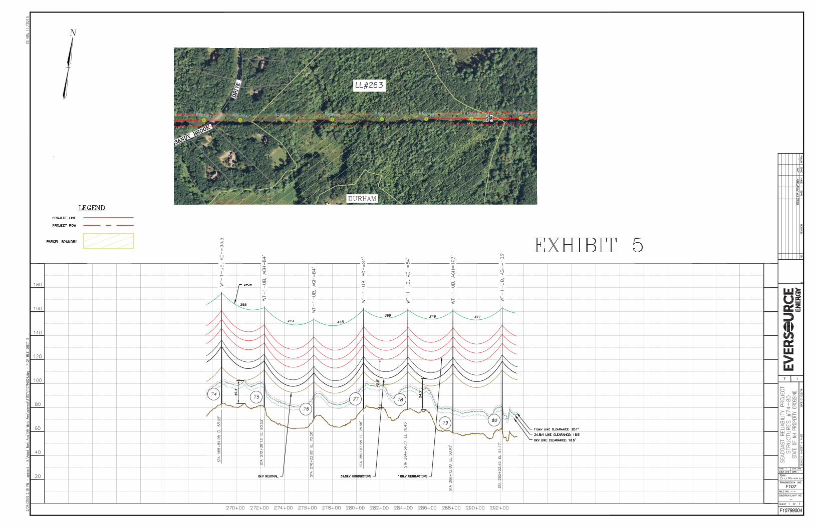
1. The design and proposed construction of this crossing is shown on the attached Eversource Energy Drawings entitled “Seacoast Reliability Project Structures #74-80, State of NH Property Crossing” (Drawing No. F10799004) marked as Exhibit 5.
2. The location of this crossing is shown on the attached Location Plan
marked as Exhibit 4.
3. Lines F107 and 3162 will cross the public land east of Sandy Brook Drive primarily on 1-pole, direct embed, steel tangent suspension structures designated as Type WT-1-UB. Details of these structures are shown on Exhibit 11. Above ground structure heights (AGH) for each of the crossing structures is shown on Exhibit 5. As shown on Exhibit 11, for the Type WT-1-UB structures the 115kV phase wires have an approximate separation at the structure of 7.5 -15 feet vertically and 0-13 feet horizontally in a delta configuration. The static wire is carried on the structure by a support bracket approximately nine inches down from the top of the structure. The 34.5kV phase wires are arranged horizontally approximately 15 feet below the lowest 115kV conductor and have an approximate separation at the structure of 0-5 feet vertically and 2.5-6 feet horizontally. The neutral wire is carried on the structure by a support bracket approximately 7.5 feet down below the 34.5kV phase wires. All NESC clearances at the structure as described in paragraphs 12 and 13 of the petition have been met by exceeding the horizontal and/or vertical clearances required.
4. Information for the mapping of property, physical features, adjacent
transmission lines and ROW boundaries were collected from various sources as detailed below:
• The property lines are based on information from Town of Durham Tax maps
• The physical features such as the location of railroads were digitized from geo-referenced aerial imagery of the project area, dated 2013.
• The existing and future limits of the electric right-of-way (ROW) as well as the road ROW are based on geo-references information received from NHDOT and ground survey, dated 2015.
• Topography and obstacle survey were from aerial LIDAR survey, dated 2013.
5. PSNH has investigated through the design and modeling process a multitude of weather and loading and service conditions to verify that proper NESC and PSNH required clearances will be maintained. The NESC clearance verifications,
17
combined with PSNH standard conductor and shield wire clearance and spacing requirements, ensure minimum clearances will be maintained under all service conditions. These conditions include the maximum operating temperature of each conductor and cable (285oF for 115kV, 212oF for 34.5kv and 120oF for 0kV), and conductor at 32oF with 0.5 inches of radial ice and 32oF with no ice. PSNH used these design conditions and all combinations thereof to determine the minimum clearance of all conductors to the both ground and aerial obstacles, between the phase conductors and OPGW cable and neutral conductors. All NESC clearances have been met by exceeding the horizontal and/or vertical clearances required. Per PSNH standards, span by span verifications were completed to validate the specified NESC clearance requirements were met. The applicable clearances mandated by the NESC and internal PSNH standards are identified and summarized below:
Table 1-Required Vertical Clearances* Vertical Clearance Type NESC Minimum Design
Clearance (ft) PSNH Standard Design Clearance (ft)
115kV to Ground- Vehicle/Horse Access**
20.1 24
34.5kV to Ground- Vehicle/Horse Access**
18.5 19.5
0kV to Ground- Vehicle/Horse Access**
15.5 15.5
115kV to 115kV (At Structure) 5.1 9 34.5kV to 34.5kV (At Structure) 2.3 4.5 115kV to 34.5kV (At Structure) 4.1 8 115kV to 0kV (At Structure) 3.4 8 34.5kV to 0kV (At Structure) 1.4 5.6 115kV to 115kV (In Span) 4.4 9 34.5kV to 34.5kV (In Span) 1.7 4.5 115kV to 34.5kV (In Span) 3.4 8 115kV to 0kV(In Span) 2.0 8 34.5kV to 0kV (In Span) 1.3 1.3 * Clearances defined in paragraphs 12 and 13 of the petition **PSNH designs all new transmission lines for vehicle access clearance regardless of accessibility ***Because PSNH designs all new lines with a neutral clearance of 18 feet the 34.5kV clearance to ground will always exceed the 18.5 feet required clearance.
Table 2-Required Horizontal Clearances* Horizontal Clearance Type NESC Minimum Design
Clearance (ft) PSNH Standard Design Clearance (ft)
115kV to 115kV (At Structure) 4.8 8 34.5kV to 34.5kV (At Structure) 1.9 5 115kV to 34.5kV (At Structure) 3.8 7 115kV to 0kV (At Structure) 3.1 7 34.5kV to 0kV (At Structure) 1.5 1.75 115kV to 115kV (In Span) 6.7 8 34.5kV to 34.5kV (In Span) 4.6 5 115kV to 34.5kV (In Span) 5.9 7 115kV to 0kV(In Span) 5.4 7 34.5kV to 0kV (In Span) 4.2 5 *Clearances defined in paragraph 13 of the petition
18
Shield wires – Due to the fact that the OPGW wire is located above the phase wires, its clearance to the water surface will always exceed the minimum required NESC distance.
condition for the maximum operating temperature of the phase conductors produces the greatest sag in the phase wires and therefore the minimum clearance to the ground. A summary of the clearances as part of this crossing is listed in the table below. These clearances exceed the vertical clearance requirements for 115kV phase conductors over roadways and ground accessible by vehicles as listed above. Table 3- 115kV Summary of Clearances at Crossing Structure (Back)
condition for the maximum operating temperature of the phase conductors produces the greatest sag in the phase wires and therefore the minimum clearance to the ground. A summary of the clearances as part of this crossing is listed in the table below. These clearances exceed the vertical clearance requirements for 34.5kV phase conductors over roadways and ground accessible by vehicles as listed above. Table 4- 34.5kV Summary of Clearances at Crossing Structure (Back)
• 0 kV Neutral- For the neutral conductors the 120oF weather condition
for the maximum operating temperature of the phase conductors produces the greatest sag in the phase wires and therefore the minimum clearance to the ground. A summary of the clearances as
19
part of this crossing is listed in the table below. These clearances exceed the vertical clearance requirements for 0kV neutral conductors over roadways and ground accessible by vehicles as listed above. Table 5- 0kV Summary of Clearances at Crossing Structure (Back)
• Conductors and Cables Horizontal Clearance – PSNH Standard
centerline spacing is based upon the geometric configuration of the structures along a line assuming a maximum 800 foot span length under 6 pounds per square foot (“psf”) sustained transverse wind. The F107 Line is spaced apart from adjacent lines as specified by PSNH standard and no span along the PSNH portion of the F107 Line exceeds an 800 foot length. Furthermore, a span by span verification was completed assuming a 9psf sustained transverse wind to ensure the horizontal clearances above were exceeded.
20
APPENDIX D
F107 Lines Spans 123-129 3850 Line Spans 9-15
State of New Hampshire- Department of Transportation NEWINGTON, NH
1. The design and proposed construction of these crossings are shown on the
attached Eversource Energy Drawings entitled “Seacoast Reliability Project Structures #123-129, State of NH Property Crossing” (Drawing No. F10799006 Sheet 1 of 1) and “Seacoast Reliability Project Structures #9-14, State of NH Property Crossing” (Drawing No. 385099001 Sheet 1 of 1) marked as Exhibit 7 and Exhibit 10, respectively.
2. The locations of these crossings are shown on the attached Location Plan
marked as Exhibit 6.
3. Line F107 will cross the public land west of the Spaulding Turnpike primarily on 1-pole, direct embed, steel tangent suspension structures designated as Type WT-2-SB. Structures 123 and 124 are a 1-pole, steel running angle structure on a concrete foundation designated as Type SPRA-BP. Structure 128 is a 1-pole, direct embed running angle structure designated as TypeWA-2. Details of these structures are shown on Exhibit 11. Above ground structure heights (AGH) for each of the crossing structures is shown on Exhibits 7 and 10. As shown on Exhibit 11, for the Type WT-2-SB structures the 115kV phase wires have an approximate separation at the structure of 7 -15.5 feet vertically and 0-13 feet horizontally in a delta configuration. The static wire is carried on the structure by a support bracket approximately nine inches down from the top of the structure. As shown on Exhibit 11, for the Type SPRA-BP structures the 115kV phase wires have an approximate separation at the structure of ten feet vertically and zero feet horizontally in a vertical configuration. The static wire is carried on the structure by a support bracket approximately nine inches down from the top of the structure. As shown on Exhibit 11, for the Type WA-2 structures the 115kV phase wires have an approximate separation at the structure of ten feet vertically and zero feet horizontally in a vertical configuration. The static wire is carried on the structure by a support bracket approximately nine inches down from the top of the structure. All NESC clearances at the structure as described in paragraphs 12 and 13 of the petition have been met by exceeding the horizontal and/or vertical clearances required.
4. Line 3850 will cross the public land west of the Spaulding Turnpike primarily on 1-pole, direct embed, wood or steel tangent structures designated at Type TAN and Type DX. Structure 10 is a 1-pole, wood or steel direct embed dead-end structure designated as Type DEA. Structures 14 and 15 are 1-pole, wood or steel direct embed dead-end structure designated as Type DE. As shown on Exhibit 11, for the Type Tan and Type DX structures the 34.5kV phase wires have an approximate separation at the structure of 0 feet vertically and 4.7 feet horizontally in a horizontal configuration. The neutral wire is carried on the structure by a support bracket approximately five feet down below the 34.5kV phase wires. As shown on Exhibit 11, for the Type DE structures
21
the 34.5kV phase wires have an approximate separation at the structure of 0 feet vertically and 4.5 feet horizontally in a horizontal configuration. The neutral wire is carried on the structure by a support bracket approximately six feet down below the 34.5kV phase wires. As shown on Exhibit 11, for the Type DEA structures the 34.5kV phase wires have an approximate separation at the structure of 0-5 feet vertically and 4.5 feet horizontally in a horizontal configuration. The neutral wire is carried on the structure by a support bracket approximately five feet down below the lowest 34.5kV phase wires. All NESC clearances at the structure as described in paragraph 13 of the petition have been met by exceeding the horizontal and/or vertical clearances required.
5. Information for the mapping of property, physical features, adjacent
transmission lines and ROW boundaries were collected from various sources as detailed below:
• The property lines are based on information from Town of Newington Tax maps
• The physical features such as the location of road were digitized from geo-referenced aerial imagery of the project area, dated 2013.
• The existing and future limits of the electric right-of-way (ROW) as well as the road ROW are based on geo-references information received from NHDOT and ground survey, dated 2015.
• Topography and obstacle survey were from aerial LIDAR survey, dated 2013.
6. PSNH has, through the design and modeling process, investigated a multitude of weather and loading and service conditions to verify that proper NESC and PSNH required clearances will be maintained. The NESC clearance verifications, combined with PSNH standard conductor and shield wire clearance and spacing requirements, ensure minimum clearances will be maintained under all service conditions. These conditions include the maximum operating temperature of each conductor and cable (285oF for 115kV, 212oF for 34.5kv and 120oF for 0kV), and conductor at 32oF with 0.5 inches of radial ice and 32oF with no ice. PSNH used these design conditions and all combinations thereof to determine the minimum clearance of all conductors to the both ground and aerial obstacles, between the phase conductors and OPGW cable and neutral conductors. All NESC clearances have been met by exceeding the horizontal and/or vertical clearances required. Per PSNH standards, span by span verifications were completed to validate the specified NESC clearance requirements were met. The applicable clearances mandated by the NESC and internal PSNH standards are identified and summarized below:
Table 1-Required Vertical Clearances* Vertical Clearance Type NESC Minimum Design
Clearance (ft) PSNH Standard Design Clearance (ft)
115kV to Ground- Vehicle/Horse Access**
20.1 24
34.5kV to Ground- Vehicle/Horse Access**
18.5 19.5
0kV to Ground- Vehicle/Horse 15.5 15.5
22
Access** 115kV to 115kV (At Structure) 5.1 9 34.5kV to 34.5kV (At Structure) 2.3 4.5 115kV to 34.5kV (At Structure) 4.1 8 115kV to 0kV (At Structure) 3.4 8 34.5kV to 0kV (At Structure) 1.4 5.6 115kV to 115kV (In Span) 4.4 9 34.5kV to 34.5kV (In Span) 1.7 4.5 115kV to 34.5kV (In Span) 3.4 8 115kV to 0kV(In Span) 2.0 8 34.5kV to 0kV (In Span) 1.3 1.3 * Clearances defined in paragraphs 12 and 13 of the petition **PSNH designs all new transmission lines for vehicle access clearance regardless of accessibility ***Because PSNH designs all new lines with a neutral clearance of 18 feet the 34.5kV clearance to ground will always exceed the 18.5 feet required clearance.
Table 2-Required Horizontal Clearances* Horizontal Clearance Type NESC Minimum Design
Clearance (ft) PSNH Standard Design Clearance (ft)
115kV to 115kV (At Structure) 4.8 8 34.5kV to 34.5kV (At Structure) 1.9 5 115kV to 34.5kV (At Structure) 3.8 7 115kV to 0kV (At Structure) 3.1 7 34.5kV to 0kV (At Structure) 1.5 1.75 115kV to 115kV (In Span) 6.7 8 34.5kV to 34.5kV (In Span) 4.6 5 115kV to 34.5kV (In Span) 5.9 7 115kV to 0kV(In Span) 5.4 7 34.5kV to 0kV (In Span) 4.2 5 *Clearances defined in paragraph 13 of the petition Shield wires – Due to the fact that the OPGW wire is located above the phase wires, its clearance to the water surface will always exceed the minimum required NESC distance.
condition for the maximum operating temperature of the phase conductors produces the greatest sag in the phase wires and therefore the minimum clearance to the ground. A summary of the clearances as part of this crossing is listed in the table below. These clearances exceed the vertical clearance requirements for 115kV phase conductors over roadways and ground accessible by vehicles as listed above. Table 3- 115kV Summary of Clearances at Crossing Structure (Back)
condition for the maximum operating temperature of the phase conductors produces the greatest sag in the phase wires and therefore the minimum clearance to the ground. A summary of the clearances as part of this crossing is listed in the table below. These clearances exceed the vertical clearance requirements for 34.5kV phase conductors over roadways and ground accessible by vehicles as listed above. Table 4- 34.5kV Summary of Clearances at Crossing Structure (Back)
• 0 kV Neutral- For the neutral conductors the 120oF weather condition
for the maximum operating temperature of the phase conductors produces the greatest sag in the phase wires and therefore the minimum clearance to the ground. A summary of the clearances as part of this crossing is listed in the table below. These clearances exceed the vertical clearance requirements for 0kV neutral conductors over roadways and ground accessible by vehicles as listed above. Table 5- 0kV Summary of Clearances at Crossing Structure (Back)
• Conductors and Cables Horizontal Clearance – PSNH Standard
centerline spacing is based upon the geometric configuration of the structures along a line assuming a maximum 800 foot span length under 6 pounds per square foot (“psf”) sustained transverse wind. The
24
F107 Line is spaced apart from adjacent lines as specified by PSNH standard and no span along the PSNH portion of the F107 Line exceeds an 800 foot length. Furthermore, a span by span verification was completed assuming a 9psf sustained transverse wind to ensure the horizontal clearances above were exceeded.
25
APPENDIX E
F107 Line Spans 131-133
State of New Hampshire-Department of Transportation NEWINGTON, NH
1. The design and proposed construction of this crossing is shown on the
attached Eversource Energy Drawings entitled “Seacoast Reliability Project Structures #131-133, State of NH Property Crossing” (Drawing No. F10799008 Sheet 1 of 1) marked as Exhibit 9.
2. The location of this crossing is shown on the attached Location Plan
marked as Exhibit 8.
3. Line F107 will cross the public land west of the Spaulding Turnpike primarily on 1-pole, direct embed, steel tangent suspension structures designated as Type WT-2-SB. Structure 133 is a 1-pole, direct embed running angle structure designated as TypeWA-2. Details of these structures are shown on Exhibit 11. Above ground structure heights (AGH) for each of the crossing structures is shown on Exhibit 9. As shown on Exhibit 11, for the Type WT-2-SB structures the 115kV phase wires have an approximate separation at the structure of 7 -15.5 feet vertically and 0-13 feet horizontally in a delta configuration. The static wire is carried on the structure by a support bracket approximately nine inches down from the top of the structure. As shown on Exhibit 11, for the Type WA-2 structures the 115kV phase wires have an approximate separation at the structure of ten feet vertically and zero feet horizontally in a vertical configuration. The static wire is carried on the structure by a support bracket approximately nine inches down from the top of the structure. All NESC clearances at the structure as described in paragraphs 12 and 13 of the petition have been met by exceeding the horizontal and/or vertical clearances required.
4. Information for the mapping of property, physical features, adjacent
transmission lines and ROW boundaries were collected from various sources as detailed below:
• The property lines are based on information from Town of Newington Tax maps
• The physical features such as the location of road were digitized from geo-referenced aerial imagery of the project area, dated 2013.
• The existing and future limits of the electric right-of-way (ROW) as well as the road ROW are based on geo-references information received from NHDOT and ground survey, dated 2015.
• Topography and obstacle survey were from aerial LIDAR survey, dated 2013.
5. PSNH has, through the design and modeling process, investigated a multitude of weather and loading and service conditions to verify that proper NESC and
26
PSNH required clearances will be maintained. The NESC clearance verifications, combined with PSNH standard conductor and shield wire clearance and spacing requirements, ensure minimum clearances will be maintained under all service conditions. These conditions include the maximum operating temperature of each conductor and cable (285oF for 115kV, 212oF for 34.5kv and 120oF for 0kV), and conductor at 32oF with 0.5 inches of radial ice and 32oF with no ice. PSNH used these design conditions and all combinations thereof to determine the minimum clearance of all conductors to the both ground and aerial obstacles, between the phase conductors and OPGW cable and neutral conductors. All NESC clearances have been met by exceeding the horizontal and/or vertical clearances required. Per PSNH standards, span by span verifications were completed to validate the specified NESC clearance requirements were met. The applicable clearances mandated by the NESC and internal PSNH standards are identified and summarized below:
Table 1-Required Vertical Clearances* Vertical Clearance Type NESC Minimum Design
Clearance (ft) PSNH Standard Design Clearance (ft)
115kV to Ground- Vehicle/Horse Access**
20.1 24
0kV to Ground- Vehicle/Horse Access**
15.5 15.5
115kV to 115kV (At Structure) 5.1 9 115kV to 0kV (At Structure) 3.4 8 115kV to 115kV (In Span) 4.4 9 115kV to 0kV(In Span) 2.0 8 * Clearances defined in paragraphs 12 and 13 of the petition **PSNH designs all new transmission lines for vehicle access clearance regardless of accessibility
Table 2-Required Horizontal Clearances* Horizontal Clearance Type NESC Minimum Design
Clearance (ft) PSNH Standard Design Clearance (ft)
115kV to 115kV (At Structure) 4.8 8 115kV to 0kV (At Structure) 3.1 7 115kV to 115kV (In Span) 6.7 8 115kV to 0kV(In Span) 5.4 7 *Clearances defined in paragraph 13 of the petition Shield wires – Due to the fact that the OPGW wire is located above the phase wires, its clearance to the water surface will always exceed the minimum required NESC distance.
condition for the maximum operating temperature of the phase conductors produces the greatest sag in the phase wires and therefore the minimum clearance to the ground. A summary of the clearances as part of this crossing is listed in the table below. These clearances exceed the vertical clearance requirements for 115kV phase conductors over roadways and ground accessible by vehicles as listed above.
27
Table 3- 115kV Summary of Clearances at Crossing Structure (Back)
• Conductors and Cables Horizontal Clearance – PSNH Standard
centerline spacing is based upon the geometric configuration of the structures along a line assuming a maximum 800 foot span length under 6 pounds per square foot (“psf”) sustained transverse wind. The F107 Line is spaced apart from adjacent lines as specified by PSNH standard and no span along the PSNH portion of the F107 Line exceeds an 800 foot length. Furthermore, a span by span verification was completed assuming a 9psf sustained transverse wind to ensure the horizontal clearances above were exceeded.