8
MONTREAL · TORONTO · CALGARY · EDMONTON · VANCOUVER THE STRENGTH WITHIN STEEL STUD, TRIMS AND ACCESSORIES FOR DRYWALL CONSTRUCTION

MONTREAL · TORONTO · CALGARY · EDMONTON · VANCOUVER
T H E S T R E N G T H W I T H I N
STEEL STUD, TR IMS AND ACCESSORIES FOR DRYWALL CONSTRUCTION
2
ww
w.b
mp
-gro
up
.co
m
STUDDESIGNATION
SPACINGo.c.(in.)
5 psf
L/120 L/240 L/360
7.5 psf
L/120 L/240 L/360
10 psf
L/120 L/240 L/360
STUDDESIGNATION
SPACINGo.c.(in.)
5 psf
L/120 L/240 L/360
7.5 psf
L/120 L/240 L/360
10 psf
L/120 L/240 L/360
250S125-18 12 12’-6” 10’-6” 9’-2” 10’-2” 9’-2” 8’-0” 8’-10” 8’-4” 7’-4”16 10’-10” 9’-6” 8’-4” 8’-10” 8’-4” 7’-4” 7’-7” 7’-7” 6’-7”24 8’-10” 8’-4” 7’-4” 7’-2” 7’-2” 6’-4” 6’-2” 6’-2” 5’-10”
362S125-18 12 15’-1” 13’-7” 11’-11” 12’-5” 11’-11” 10’-5” 10’-8” 10’-8” 9’-5”16 13’-1” 12’-5” 10’-10” 10’-8” 10’-8” 9’-5” 9’-4” 9’-4” 8’-7”24 10’-8” 10’-8” 9’-5” 8’-8” 8’-8” 8’-4” 7’-7” 7’-7” 7’-6”
Notes:1) Studs are 0.0179 in. base
steel thickness.2) Limiting heights are based
on continuous support ofeach flange over the fullheight of the stud.
3) Heights based on steelproperties only, calculatedin accordance with CSA-S136-2002.
8’-4”--
10’-5”9’-8”8’-11”
14’-10”13’-0”11’-0”
121624
121624
121624
14’-5”12’-11”11’-4”
16’-11”15’-1”13’-0”
21’-5”19’-0”16’-2”
12’-0”11’-4”10’-5”
15’-4”14’-4”13’-0”
21’-5”19’-0”16’-2”
10’-5”9’-10”9’-1”
13’-4”12’-5”11’-5”
19’-6”18’-2”16’-2”
11’-10”10’-7”9’-4”
13’-7”12’-1”10’-5”
17’-2”15’-2”12’-11”
10’-5”9’-10”9’-1”
13’-2”12’-1”10’-5”
17’-2”15’-2”12’-11”
9’-1”8’-6”
-
11’-6”10’-10”9’-11”
16’-10”15’-2”12’-11”
10’-2”9’-2”8’-1”
11’-8”10’-5”8’-11”
14’-10”13’-0”11’-0”
9’-6”8’-11”8’-1”
11’-8”10’-5”8’-11”
14’-10”13’-0”11’-0”
250S125-18
362S125-18
600S125-18
Notes:1) Studs are 0.0179 in. base
steel thickness.2) Composite wall sheathed
both sides full height with1/2" gypsum wallboard.
3) Sheathing attached with#6 screws minimum at 12" o.c. maximum
4) Maximum heights arealso applicable to wallssheathed with gypsumboard greater than 1/2 in.thick and multiple layersof gypsum board.
Reproduced with the permission of CSSBI. The Stud Designation follows the industry standard format.
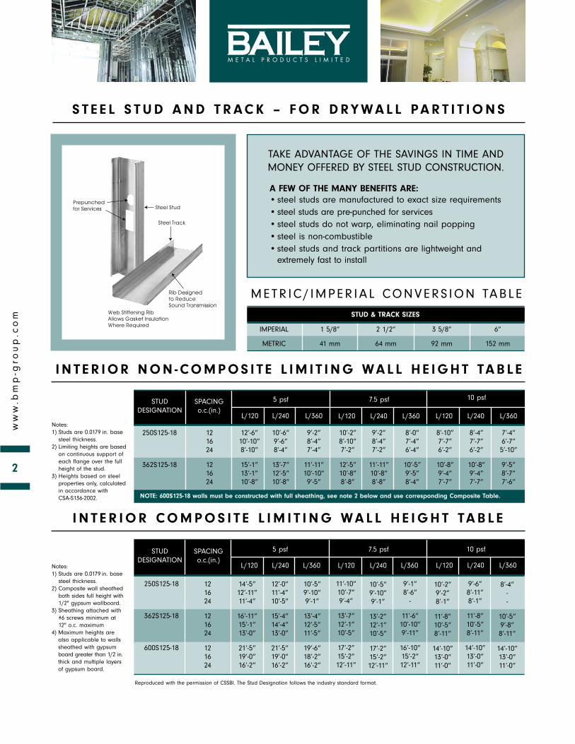
A FEW OF THE MANY BENEFITS ARE:•steel studs are manufactured to exact size requirements• steel studs are pre-punched for services• steel studs do not warp, eliminating nail popping•steel is non-combustible•steel studs and track partitions are lightweight and
extremely fast to install
Steel StudPrepunchedfor Services
Web Stiffening Rib Allows Gasket Insulation Where Required
Rib Designed to Reduce Sound Transmission
Steel Track
I N T E R I O R N O N - CO M P O S I T E L I M I T I N G WA L L H E I G H T TA B L E
I N T E R I O R CO M P O S I T E L I M I T I N G WA L L H E I G H T TA B L E
S T E E L S T U D A N D T R A C K – F O R D RY WA L L PA R T I T I O N S
TAKE ADVANTAGE OF THE SAVINGS IN TIME ANDMONEY OFFERED BY STEEL STUD CONSTRUCTION.
METR IC/ IMPER IAL CONVERS ION TABLE
STUD & TRACK SIZES
IMPERIAL 1 5/8” 2 1/2” 3 5/8” 6”
METRIC 41 mm 64 mm 92 mm 152 mm
NOTE: 600S125-18 walls must be constructed with full sheathing, see note 2 below and use corresponding Composite Table.

3
ww
w.b
mp
-gro
up
.co
m
D - 100 - 9 0° DRYWALL CORNER BEAD
This Drywall Corner Bead, manufactured using sturdy zinc-coated steel,provides excellent protection to external corners. The holes and knurledsurface provide an excellent “key” for the joint compound. This Corner Beadcan be applied either with nails, screws or clinch-on tools.
D - 100 - 130° DRYWALL CORNER BEAD
This Drywall Corner Bead was specifically designed to provide protection toexternal 130° wide angle corners. 130° Corner Bead is available from stock with1 1/4” or 1 1/8” flanges. (This is to fit 135° corners)
D - 2 00 DRYWALL METAL TR IM
For use with 1/2” and 5/8” Wallboard
This Drywall Trim provides a neat finish and solid protection to gypsumwallboard at window and door jambs where wood trim is omitted. Holes in theflange provide a “key” for the joint cement.
D - 4 00 METAL TR IM
Provides edge protection at window and door openings, and wherewallboard butts against concrete or other materials. Finishing cement isoptional. (For use with 3/8”, 1/2” or 5/8” wallboard)
4 411 CHANNEL TR IM
A tapeable steel casing that provides maximum protection at door andwindow jambs. Quickly installed by nailing through channel and board intothe jamb or framing. (For use with 1/2” or 5/8” wallboard)
D R Y W A L L C O R N E R B E A D & M E TA L T R I M S

4
ww
w.b
mp
-gro
up
.co
m
2 ” DEEP L EG TRACK
Bailey 2” Deep Leg Track is designed for applications where wall height willvary slightly along its length, due to uneven concrete, etc.
C ARPET BASE TRACK
Bailey Carpet Base Track is manufactured with an extra deep leg. This leg canbe varied to suit, while stocked in 4 7/8” depth for 2 1/2” and 3 5/8” stud.Available in some locations.
The most common application is to provide a backing for the attachment ofcarpet where it is extended up the wall.
D - 3 00 DRYWALL REVEAL TR IM
This Drywall Trim is designed to provide crisp clean reveals around openingsor at ceilings and floors. The holes and knurled surface provides an excellent“key” for finishing with joint compound. For use with 1/2” drywall to provide a1/2” or 5/8” reveal.
D - 8 00 DRYWALL REVEAL TR IM
A solid reveal trim for use at doors, windows, ceilings, etc. The surface isready for painting and additional finishing is not required. Available for 1/2”or 5/8” drywall. D-800 provided with a 1/2” reveal as a standard. Customreveals are also readily available.
D R Y W A L L R E V E A L T R I M S
D E E P L E G T R A C K S
5
ww
w.b
mp
-gro
up
.co
m
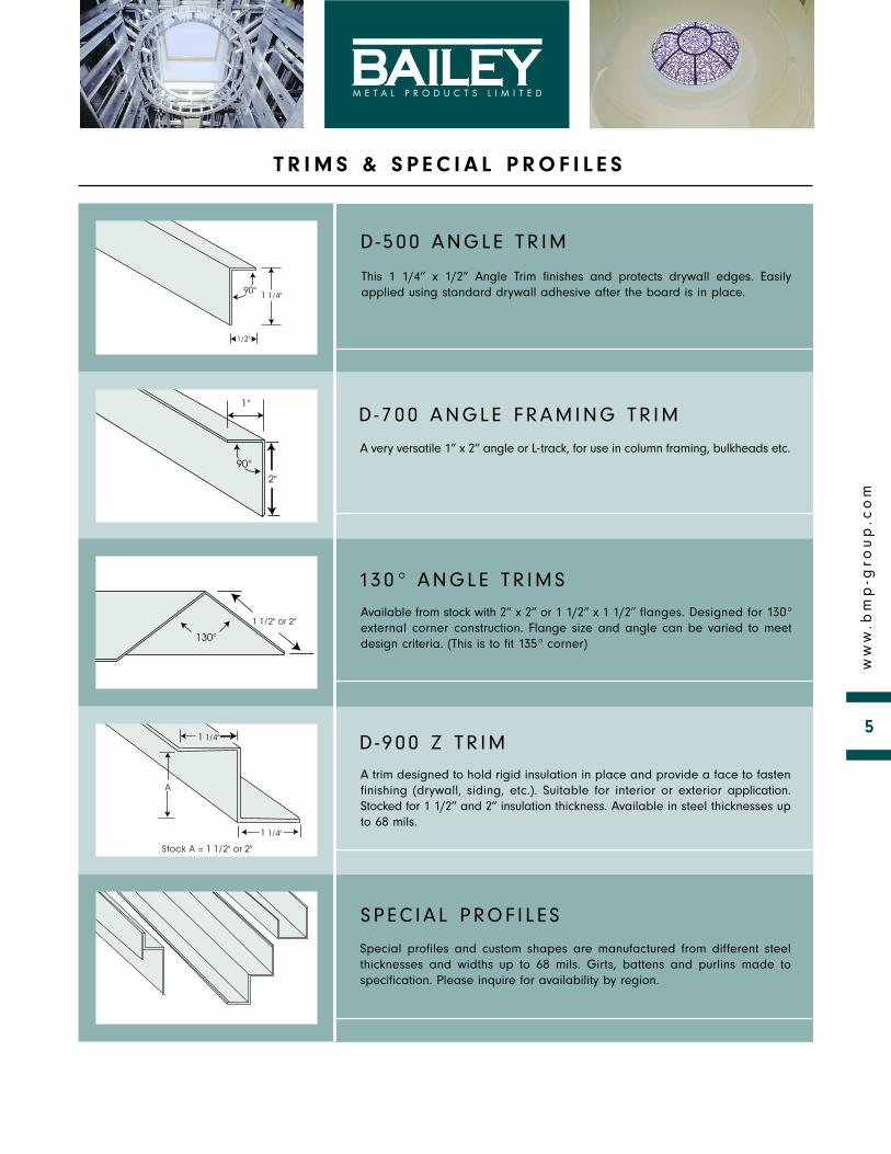
D - 5 00 ANGLE TR IM
This 1 1/4” x 1/2” Angle Trim finishes and protects drywall edges. Easilyapplied using standard drywall adhesive after the board is in place.
D - 7 00 ANGLE FRAMING TR IM
A very versatile 1” x 2” angle or L-track, for use in column framing, bulkheads etc.
13 0° ANGLE TR IMS
Available from stock with 2” x 2” or 1 1/2” x 1 1/2” flanges. Designed for 130°external corner construction. Flange size and angle can be varied to meetdesign criteria. (This is to fit 135° corner)
D - 9 00 Z TR IM
A trim designed to hold rigid insulation in place and provide a face to fastenfinishing (drywall, siding, etc.). Suitable for interior or exterior application.Stocked for 1 1/2” and 2” insulation thickness. Available in steel thicknesses upto 68 mils.
S P EC IA L PROF I L E S
Special profiles and custom shapes are manufactured from different steelthicknesses and widths up to 68 mils. Girts, battens and purlins made tospecification. Please inquire for availability by region.
T R I M S & S P E C I A L P R O F I L E S
6
ww
w.b
mp
-gro
up
.co
m
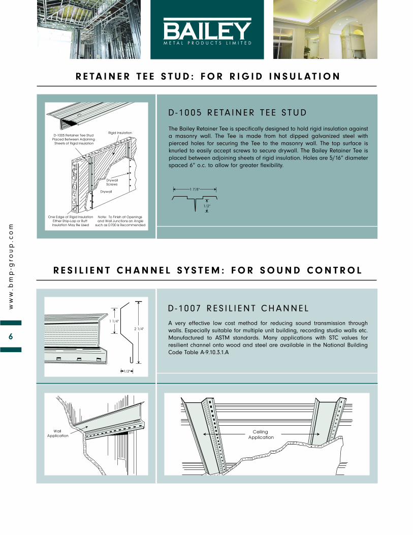
D - 1005 RE TA INER T E E S TUD
The Bailey Retainer Tee is specifically designed to hold rigid insulation againsta masonry wall. The Tee is made from hot dipped galvanized steel withpierced holes for securing the Tee to the masonry wall. The top surface isknurled to easily accept screws to secure drywall. The Bailey Retainer Tee isplaced between adjoining sheets of rigid insulation. Holes are 5/16” diameterspaced 6” o.c. to allow for greater flexibility.
D - 1007 RES I L I ENT CHANNEL
A very effective low cost method for reducing sound transmission throughwalls. Especially suitable for multiple unit building, recording studio walls etc.Manufactured to ASTM standards. Many applications with STC values forresilient channel onto wood and steel are available in the National BuildingCode Table A-9.10.3.1.A
R E TA I N E R T E E S T U D : F O R R I G I D I N S U L AT I O N
R E S I L I E N T C H A N N E L S Y S T E M : F O R S O U N D C O N T R O L
7
ww
w.b
mp
-gro
up
.co
m
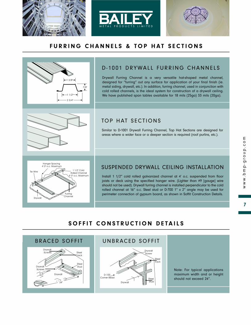
D - 1001 DRYWALL FURR ING CHANNELS
Drywall Furring Channel is a very versatile hat-shaped metal channel,designed for “furring” out any surface for application of your final finish (ie.metal siding, drywall, etc.). In addition, furring channel, used in conjunction withcold rolled channels, is the ideal system for construction of a drywall ceiling.We have published span tables available for 18 mils (25ga) 33 mils (20ga).
TOP HAT S ECT IONS
Similar to D-1001 Drywall Furring Channel, Top Hat Sections are designed forareas where a wider face or a deeper section is required (roof purlins, etc.).
SUSPENDED DRYWALL CEILING INSTALLATION
Install 1 1/2” cold rolled galvanized channel at 4’ o.c. suspended from floorjoists or deck using the specified hanger wire. (Lighter than #9 [gauge] wireshould not be used). Drywall furring channel is installed perpendicular to the coldrolled channel at 16” o.c. Steel stud or D-700 1” x 2” angle may be used forperimeter connection of gypsum board, as shown in Soffit Construction Details.
B RACED SOFF I T
Note: For typical applicationsmaximum width and or heightshould not exceed 24”.
F U R R I N G C H A N N E L S & TO P H AT S E C T I O N S
S O F F I T C O N S T R U C T I O N D E TA I L S
UNBRACED SOFF I T
Applicable standards for Steel Stud Framing, Trims and Accessories for NonStructural Framing are as follows:
PROFILE, STEEL THICKNESS AND DIMENSIONS – ASTM C645(With permissible tolerance) for stud track and furring channel.
GRADE OF STEEL – ASTM A1003For sheet metal, metallic and non metallic coated
COATING (GALVANIZING)Zinc/galvanized coated steel to – ASTM A653Aluminum zinc coated steel to – ASTM A792
INSTALLATION – ASTM C754
STANDARDS FOR TRIMS AND ACCESSORIES – ASTM C1047
In addition to the products shown within this catalogue, Bailey Metal Productsis a leading manufacturer of:
• Suspended ceiling grid systems
• Lightweight steel framing systems for axial and wind load bearing applications
• Metal lath and accessories for plastering
• Related fasteners and fittings
• Platinum, a series of Goldline® Paper Bead and Trims
• COMFLOR® Composite Floor System
• Brick Connectors
• Floor Joist Systems
S TA N D A R D S
MONTREALLES PRODUITS METALLIQUES BAILEY LTEE
5890 Avenue AndoverVille Mont-Royal QC H4T 1H4
Tel: (514) 735 3455(800) 263 3455
Fax: (514) 735 5052
TORONTO
One Caldari RoadConcord ON L4K 3Z9Tel: (905) 738 6738
(800) 668 2154 Fax: (905) 738 5712
BAILEY METAL PRODUCTS LIMITED
CALGARY
2515 Centre Avenue S.E.Calgary AB T2A 2L1Tel: (403) 248 3536
(800) 665 2013 Fax: (403) 248 0288
VANCOUVER
7715 Anvil WaySurrey BC V3W 6A2Tel: (604) 590 5100
(800) 818 2666Fax: (604) 599 5371
EDMONTON
5710 Roper Road N.W., Suite 101Edmonton AB T6B 3G7
Tel: (780) 462 5757(800) 563 1751
Fax: (780) 465 3791 3296
-070
4-65
00
[email protected] · www.bmp-group.com


![M100 Shapes LED Recessed [L10/L1R] selux€¦ · After Drywall Flange Mounting (SF3) 1. Drywall/Drywall screw (Ref.) 2. Drywall/Drywall (Ref.) 3. 1/6” Plaster skimcoat (Ref.) 4.](https://static.documents.pub/doc/80x56/5f54633924da634fd0733121/m100-shapes-led-recessed-l10l1r-selux-after-drywall-flange-mounting-sf3-1.jpg)


