67
THE STRUT-AND-TIE MODEL OF CONCRETE STRUCTURES By Dr. C. C. Fu, Ph.D., P.E, The BEST Center University of Maryland Presented to The Maryland State Highway Administration August 21, 2001
| Date post: | 29-Mar-2018 |
| Category: |
Documents |
| Upload: | dinhkhuong |
| View: | 216 times |
| Download: | 3 times |

THE STRUT-AND-TIE MODELOF CONCRETE STRUCTURES
ByDr. C. C. Fu, Ph.D., P.E,
The BEST CenterUniversity of Maryland
Presented toThe Maryland State Highway Administration
August 21, 2001

IntroductionThe Strut-and-Tie is a unified approach that considers all load effects (M, N, V, T) simultaneouslyThe Strut-and-Tie model approach evolves as one of the most useful design methods for shear critical structures and for other disturbed regions in concrete structuresThe model provides a rational approach by representing a complex structural member with an appropriate simplified truss modelsThere is no single, unique STM for most design situations encountered. There are, however, some techniques and rules, which help the designer, develop an appropriate model

History and Specifications
The subject was presented by Schlaich et al (1987) and also contained in the texts by Collins and Mitchell (1991) and MacGregor (1992)One form of the STM has been introduced in the new AASHTO LRFD Specifications (1994), which is its first appearance in a design specification in the USIt will be included in ACI 318-02 Appendix A

Bernoulli Hypothesis
Bernoulli hypothesis states that: " Plane section remain plane after bending…"Bernoulli's hypothesis facilitates the flexural design of reinforced concrete structures by allowing a linear strain distribution for all loading stages, including ultimate flexural capacity
N.A.

St. Venant’s Principle
St. Venant's Principle states that: " The localized effects caused by any load acting on the body will dissipate or smooth out within regions that are sufficiently away from the location of the load…"

B- & D-Regions
for Various Types of Members

Design of B & D Regions
The design of B (Bernoulli or Beam) region is well understood and the entire flexural behavior can be predicted by simple calculationEven for the most recurrent cases of D (Disturbed or Discontinuity) regions (such as deep beams or corbels), engineers' ability to predict capacity is either poor (empirical) or requires substantial computation effort (finite element analysis) to reach an accurate estimation of capacity

STM for
Simple Span Beam

Feasible Inclined Angle θSwiss Code: 0.5 ≤ Cot θ ≤ 2.0 (θ=26° to 64°)European Code: 3/5 ≤ Cot θ ≤ 5/3 (θ=31° to 59°)Collin’s & Mitchellsθmin = 10 + 110(Vu/[φfc′bwjd]) degθmax = 90 - θmin degACI 2002: θmin =25°; (25° ≤ θrecom ≤ 65° here)If small θ is assumed in the truss model, the compression strength of the inclined strut is decreased.

STM of a Deep Beam
ACI Section 10.7.1 For Deep Beam:L/d < 5/2 for continuous span; < 5/4 for simple spanACI Section 11.8: L/d <5 (Shear requirement)

Deep Beam Stress and Its
STM Model

Transition from Deep Beam to Beam

STM Model for a
Two-span Continuous
Beam

Basic Concepts
Strut-and-Tie Model: A conceptual framework where the stress distribution in a structure is idealized as a system of
ConcreteConnectionNode
ReinforcementTension Member
Tie or Stirrup
ConcreteCompression Member
Strut

Examples of STM Models

Strut Angle of STM Model
A STM developed with struts parallel to the orientation of initial cracking will behave very well A truss formulated in this manner also will make the most efficient use of the concrete because the ultimate mechanism does not require reorientation of the struts

Lower Bound Theorem of Plasticity
A stress field that satisfies equilibrium and does not violate yield criteria at any point provides a lower-bound estimate of capacity of elastic-perfectly plastic materialsFor this to be true, crushing of concrete (struts and nodes) does not occur prior to yielding of reinforcement (ties or stirrups)

Limitation of The Truss Analogy
The theoretical basis of the truss analogy is the lower bound theorem of plasticityHowever, concrete has a limited capacity to sustain plastic deformation and is not an elastic-perfectly plastic materialAASHTO LRFD Specifications adopted the compression theory to limit the compressive stress for struts with the consideration of the condition of the compressed concrete at ultimate

Prerequisites
Equilibrium must be maintainedTension in concrete is neglectedForces in struts and ties are uni-axialExternal forces apply at nodesPrestressing is treated as a loadDetailing for adequate anchorage
Problems in STM Applications
1.How to construct a Strut-and-Tie model?
2.If a truss can be formulated, is it adequate or is there a better one?
3.If there are two or more trusses for the same structure, which one is better?

Struts
A. Compression struts fulfill two functions in the STM: 1. They serve as the compression chord of
the truss mechanism which resists moment
2. They serve as the diagonal struts which transfer shear to the supports
B. Diagonal struts are generally oriented parallel to the expected axis of cracking

Types of Struts
There are three types of struts that will be discussed:
1. The simplest type is the “prism” which has a constant width
2. The second form is the “bottle” in which the strut expands or contracts along its length
3. The final type is the “fan” where an array of struts with varying inclination meet at or radiate from a single node

Three Types of Struts

Compression Struts

Ties
Tensions ties include stirrups, longitudinal (tension chord) reinforcement, and any special detail reinforcementA critical consideration in the detailing of the STM is the provision of adequate anchorage for the reinforcementIf adequate development is not provided, a brittle anchorage failure would be likely at a load below the anticipated ultimate capacity

Nodes
Nodes are the connections of the STM, i.e., the locations at which struts and ties convergeAnother way of describing a node is the location at which forces are redirected within a STM

Type of Singular Nodes
(Schlaich et al
1987)

Idealized Forces at Nodal Zones

Singular and
Smeared Nodes

STM Model Design ConceptThe successful use of the STM requires an understanding of basic member behavior and informed engineering judgment In reality, there is almost an art to the appropriate use of this technique The STM is definitely a design tool for thinking engineers, not a cookbook analysis procedure The process of developing an STM for a member is basically an iterative, graphical procedure

STM Model Design FlowChart
Methods for Formulating STM Model
Elastic Analysis based on Stress TrajectoriesLoad Path ApproachStandard Model

Elastic Analysis for the
STM Model A

Elastic Analysis for the STM Models B & C

Elastic Analysis Approach Procedures
1. Isolate D-regions2. Complete the internal stresses on the
boundaries of the element3. Subdivide the boundary and compute
the force resultants on each sub-length4. Draw a truss to transmit the forces from
boundary to boundary of the D-region5. Check the stresses in the individual
members in the truss

STM Model C Example
using Elastic
Analysis

STM Model C Example Reinforcement

Load Path
Approach (Schlaich
et al. 1987)

Example of Determining STM Model Geometry

Factors Affecting Size of Compression Strut
Location and distribution of reinforcement (tie) and its anchorageSize and location of bearing

Nodal ZonesThese dimensions are determined for each element using (1) the geometry of the member and the STM,(2) the size of bearings, (3) the size of loaded areas, (4) the location and distribution of reinforcement, and (5) the size of tendon anchorages, if any
Struts and ties should be dimensioned so that the stresses within nodes are hydrostatic, i.e., the stress on each face of the node should be the same
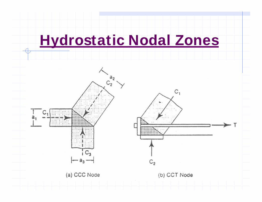
Hydrostatic Nodal Zones

Cracking of Compression Strut
bef=a+λ/6
T=C(1-a/bef)/4

STM Models A & B for Anchorage Zones

STM Models C & D for Anchorage Zones

Examples of Good
and Poor STM
Models
• Good Model is more closely approaches to the elastic stress trajectories• Poor model requires large deformation before the tie can yield; violate the
rule that concrete has a limited capacity to sustain plastic deformation

Nonlinear finite element comparison of three possible models of a short cantilever
(d) behaves almost elastically until anticipated failure load
(c) requires the largest amount of plastic deformation; thus it is more likely to collapse before reaching the failure load level

STM Model for a Ledged End

Beam-Column Opening Joints
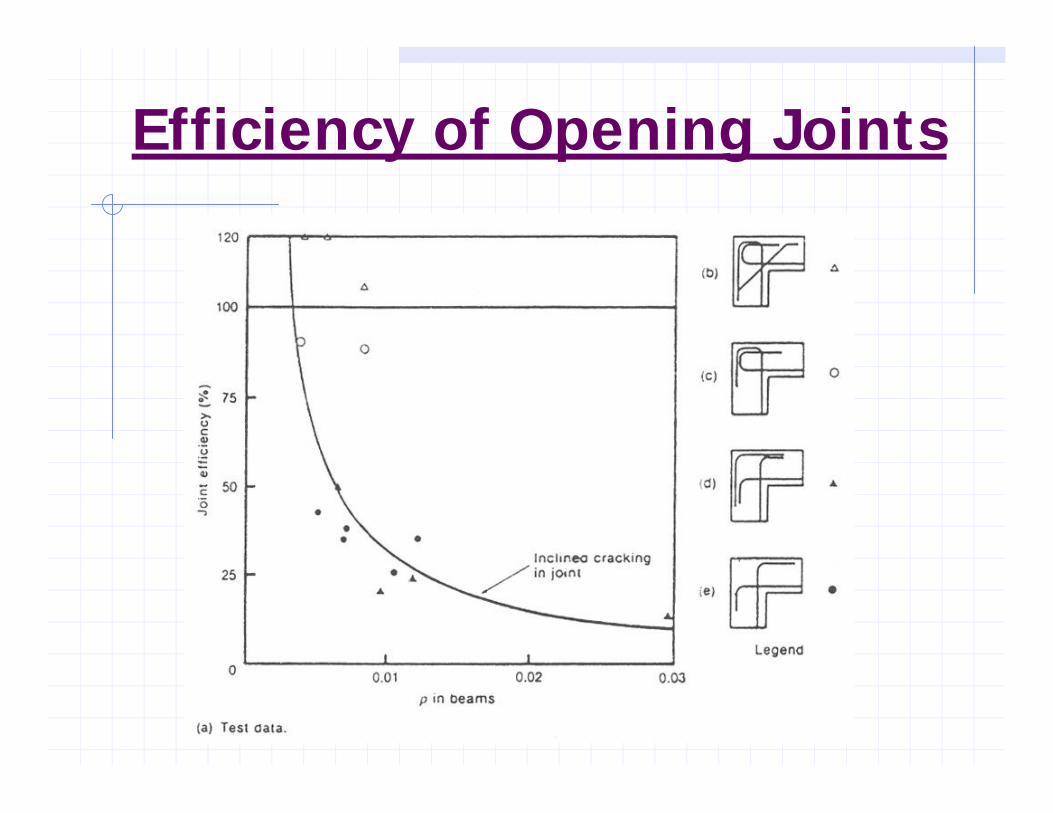
Efficiency of Opening Joints

T-Joints

Concentrated Load on a Bearing Wall

STM Models
(a)Tensile Flange
w/Opening(b)
Compression Flange
w/Opening

STM Models (c) Web supported by Diaphragm
(d) Pier and Diaphragm w/Single Support

STM Models (e) Other Model for Diaphragm
(f) Pier and Diaphragm w/Two Supports

STM Models
(g) Piers on a Pile Cap

Examples of STM Models & Reinforcement (Schlaich et al 1987)

Limiting Stresses for Truss Elements

Limiting Compressive Stress in StrutAASHTO LRFD 5.6.3.3.3
'
1
'
85.01708.0 cc
cu ff
f ≤+
=ε
where:
e1 = (es + 0.002) cot2 as
fcu = the limiting compressive stress
as = the smallest angle between the compressivestrut and adjoining tension ties (DEG)
es = the tensile strain in the concrete in thedirection of the tension tie (IN/IN)

Simplified Values for Limiting Compressive Stress in Strut, fcu (Schlaich et al. 1987)
For an undisturbed and uniaxial state of compressive stress:
fcu = 1.0 (0.85 fc?) = 0.85 fc
?
If tensile strains in the cross direction or transverse tensile reinforcement may cause cracking parallel to the strut with normal crack width:fcu = 0.8 (0.85 fc
?) = 0.68 fc?
As above for skew cracking or skew reinforcement:fcu = 0.6 (0.85 fc
?) = 0.51 fc?
For skew cracks with extraordinary crack width – such cracks must be expected if modeling of the struts departs significantly from the theory of elasticity’s flow of internal forces:fcu = 0.4 (0.85 fc
?) = 0.34 fc?

Strength of Compressive StrutAASHTO LRFD 5.6.3.3.3
Pr = F Pn (LRFD 5.6.3.2-1)
Pn = fcu Acs (LRFD 5.6.3.3.1-1)
where:
F = 0.70 for compression in strut-and-tie models(LRFD 5.5.4.2.1)
Acs = effective cross-sectional area of strut(LRFD 5.6.3.3.2)

ACI 2002 STM Model
un FF ≥φDesign of struts, ties, and nodal zones shall be based on:
The nominal compressive strength of a strut without longitudinal reinforcement:
ccuns AfF =The effective compressive strength of the concretein a strut is:
'85.0 cscu ff β=

ACI 2002 STM Model
The nominal strength of a tie shall be taken as:
( )psepsystnt ffAfAF ∆++=
The nominal compression strength of a nodal zone shall be:
ncunn AfF =
The strength of a longitudinally reinforced strut is:''
ssccuns fAAfF +=

Findings of STM Model
The STM formulation that requires the least volume of steel will be the solution that best models the behavior of a concrete memberThis approach holds great promise for DOTs and design offices which could develop or obtain standard STMs for certain commonly encountered situationsStandard reinforcement details based on an STM could be developed for common situationsThe STM then could be reviewed and revised if any parameters change

Hammerhead Pier Example

Hammerhead Pier STM Model

Spreadsheet Calculation of STM Model Examples
Abutment on Pile Model ExampleWalled Pier Model Example


