28
Surgical Technique The Subchondroplasty ® (SCP ® ) Procedure for the Shoulder
Surgical Technique
The Subchondroplasty® (SCP®)Procedure for the Shoulder
2
THE
SUB
CH
ON
DR
OP
LAST
Y®
PR
OC
EDU
RE The Subchondroplasty® (SCP)® Procedure
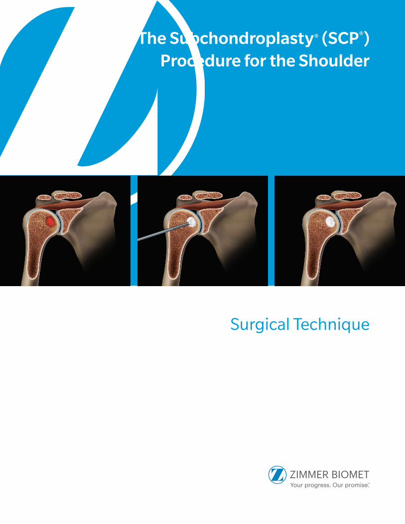
The Subchondroplasty Procedure is a minimally-invasive, fluoroscopically-assisted procedure that targets and fills
subchondral bone defects with AccuFill® Bone Substitute Material (BSM), a hard-setting, biomimetic bone substitute. It is
usually performed with arthroscopy of the affected shoulder, for visualization and treatment of findings inside the joint.
Some procedures may be performed through a mini-open or open approach, as needed for access or visualization of
joint findings.
The Subchondroplasty Procedure consists of four components:
PREOPERATIVE PLAN: Identify the bone defect on fat-suppressed MRI; plan approach and trajectory based
on defect location.
TARGET THE BONE DEFECT: Using intraoperative fluoroscopy and arthroscopy, as needed, localize the bone defect
relative to MRI findings.
ACCESS THE DEFECT: Drill the appropriate AccuPort® Delivery Cannula to the bone defect.
FILL THE BONE DEFECT: Inject AccuFill BSM into the bone defect.
AccuFill BSM Indications for Use:
AccuFill Injectable Bone Substitute Material is an injectable, self-setting, macroporous, osteoconductive, calcium
phosphate bone graft substitute material that is intended for use to fill bony voids or gaps of the skeletal system of the
extremities, spine (i.e., posterolateral spine), and the pelvis that are not intrinsic to the stability of the bony structure.
These defects may be surgically created osseous defects or osseous defects created from traumatic injury to the bone.
AccuFill Injectable Bone Substitute Material is a bone graft substitute that resorbs and is replaced with new bone
during the healing process.
3
TAB
LE OF C
ON
TENTS
PREOPERATIVE PLANNING ....................................................................................... 4
SURGICAL TECHNIQUE ............................................................................................. 6
OR Setup/Patient Positioning ........................................................................................................ 6
Lateral Decubitus .....................................................................................................................7
Beach Chair .............................................................................................................................8
Targeting and Accessing Bone Defects .........................................................................................10
Humeral Head .......................................................................................................................10
Implant Placement: Filling the Bone Defect ..................................................................................12
AccuFill BSM Mixing Technique .............................................................................................12
Injecting AccuFill BSM ...........................................................................................................14
Considerations for Targeting
Greater Tuberosity .................................................................................................................17
Glenoid .................................................................................................................................18
IMPLANTS AND INSTRUMENTS ............................................................................... 22
AccuPort Delivery Cannulas .........................................................................................................22
AccuFill BSM Bowl Mixing Technique ...........................................................................................23
Ordering Information ..................................................................................................................24
Contents
4
PR
EOP
ERA
TIV
E P
LAN
NIN
G Preoperative Plan
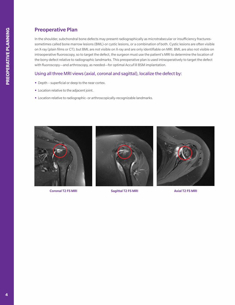
In the shoulder, subchondral bone defects may present radiographically as microtrabecular or insufficiency fractures-
sometimes called bone marrow lesions (BML)-or cystic lesions, or a combination of both. Cystic lesions are often visible
on X-ray (plain films or CT); but BML are not visible on X-ray and are only identifiable on MRI. BML are also not visible on
intraoperative fluoroscopy, so to target the defect, the surgeon must use the patient’s MRI to determine the location of
the bony defect relative to radiographic landmarks. This preoperative plan is used intraoperatively to target the defect
with fluoroscopy—and arthroscopy, as needed—for optimal AccuFill BSM implantation.
Using all three MRI views (axial, coronal and sagittal), localize the defect by:
• Depth – superficial or deep to the near cortex.
• Location relative to the adjacent joint.
• Location relative to radiographic- or arthroscopically-recognizable landmarks.
Sagittal T2 FS MRICoronal T2 FS MRI Axial T2 FS MRI
5
PR
EOP
ERA
TIVE P
LAN
NIN
G
Preoperative Plan
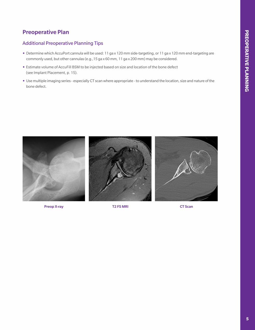
Additional Preoperative Planning Tips
• Determine which AccuPort cannula will be used: 11 ga x 120 mm side-targeting, or 11 ga x 120 mm end-targeting are
commonly used, but other cannulas (e.g.,15 ga x 60 mm, 11 ga x 200 mm) may be considered.
• Estimate volume of AccuFill BSM to be injected based on size and location of the bone defect
(see Implant Placement, p. 15).
• Use multiple imaging series - especially CT scan where appropriate - to understand the location, size and nature of the
bone defect.
T2 FS MRIPreop X-ray CT Scan
SUR
GIC
AL
TEC
HN
IQU
E
6 7
Surgical Technique
The Subchondroplasty Procedure is performed along with arthroscopy of the shoulder, for visualization and treatment
of findings inside the joint. After injection of AccuFill BSM into the defect, the scope also allows evaluation for and
evacuation of any material that has extravasated into the joint. Note, however, that while the AccuPort injection
cannulas are in place (see Implant Placement, p. 14), take care while manipulating the arm and shoulder during
scoping, to avoid bending forces on the cannula that may damage the cannula or surrounding bone.
NOTE:
Additional arthroscopic procedures involving the operative bone, including anchor drilling, should not be
performed until the BSM is allowed to set and the cannula has been removed, to prevent extravasation of unset
material into the joint.
NOTE:
Although uncommon, if extravasation of AccuFill BSM occurs, the material should be removed from the joint using
the shaver and irrigation.
Important Information: The use of AccuFill BSM is not intended to be intrinsic to the stability of the bony structure.
Radiographic studies should be used to confirm that the adjacent cortical bone is intact.
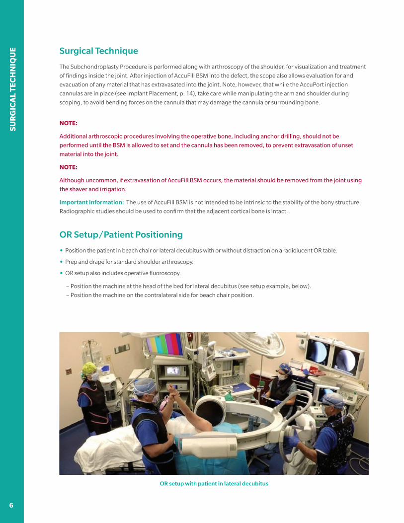
OR Setup/Patient Positioning
• Position the patient in beach chair or lateral decubitus with or without distraction on a radiolucent OR table.
• Prep and drape for standard shoulder arthroscopy.
• OR setup also includes operative fluoroscopy.
– Position the machine at the head of the bed for lateral decubitus (see setup example, below).
– Position the machine on the contralateral side for beach chair position.
OR setup with patient in lateral decubitus
6 7
SUR
GIC
AL TEC
HN
IQU
E
OR Setup/Patient Positioning
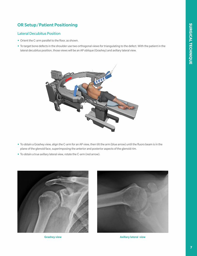
Lateral Decubitus Position
• Orient the C-arm parallel to the floor, as shown.
• To target bone defects in the shoulder use two orthogonal views for triangulating to the defect. With the patient in the
lateral decubitus position, those views will be an AP oblique (Grashey) and axillary lateral view.
• To obtain a Grashey view, align the C-arm for an AP view, then tilt the arm (blue arrow) until the fluoro beam is in the
plane of the glenoid face, superimposing the anterior and posterior aspects of the glenoid rim.
• To obtain a true axillary lateral view, rotate the C-arm (red arrow).
Grashey view Axillary lateral view
SUR
GIC
AL
TEC
HN
IQU
E
8 9
OR Setup/Patient Positioning
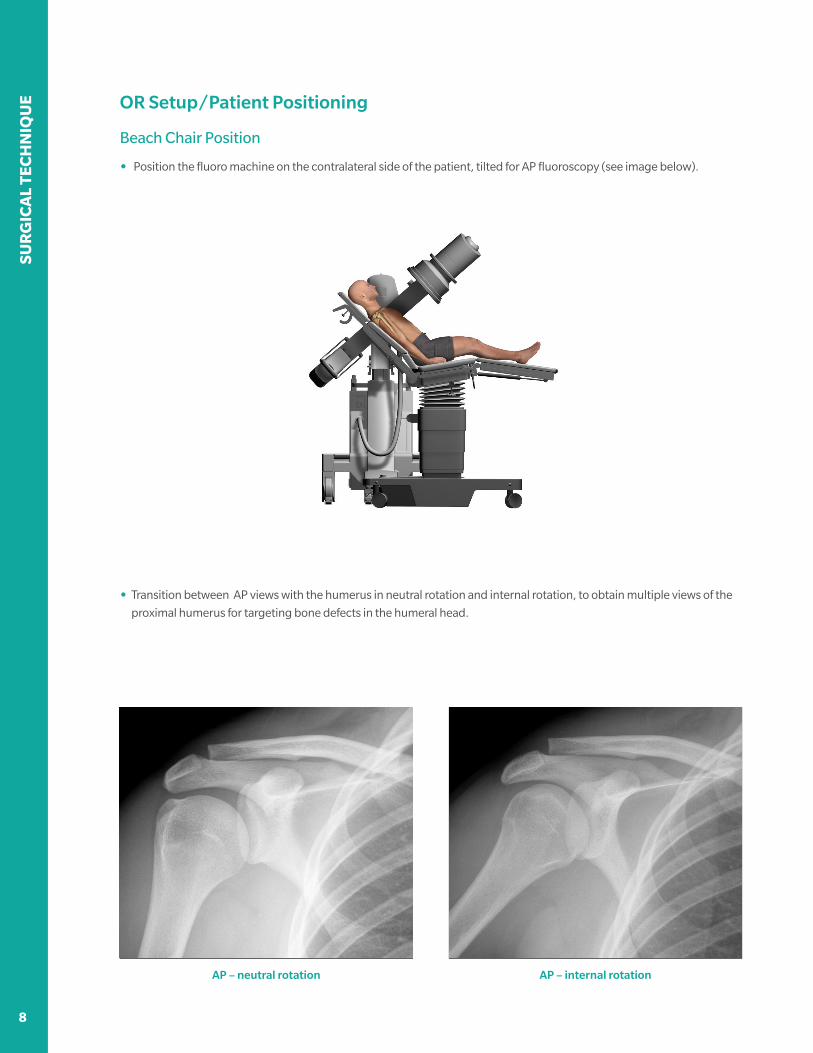
Beach Chair Position
• Position the fluoro machine on the contralateral side of the patient, tilted for AP fluoroscopy (see image below).
• Transition between AP views with the humerus in neutral rotation and internal rotation, to obtain multiple views of the
proximal humerus for targeting bone defects in the humeral head.
AP – neutral rotation AP – internal rotation

8 9
SUR
GIC
AL TEC
HN
IQU
E
OR Setup/Patient Positioning
Beach Chair Position – Alternative C-arm Setup
In some patients, particularly those with a large soft tissue envelope around the joint, rotating the patient’s arm to
obtain AP and lateral views might place undue bending stress on the cannula. To avoid this, an alternative fluoro
machine setup allows the C-arm to be moved between AP and scapular Y views without moving the patient’s arm.
Position the fluoro machine on the contralateral side of the operative shoulder, with the C-arm base angled 45° to the
table axis (images, above).
• First, find optimal machine position by setting up to obtain a scapular Y view (image on left).
• Then, rotate the C-arm to AP until an optimal AP image is obtained (image on right).
• Use both views to target the bony defects of the humeral head.
Scapular Y view AP view
SUR
GIC
AL
TEC
HN
IQU
E
10 11
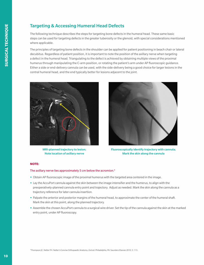
Targeting & Accessing Humeral Head Defects
The following technique describes the steps for targeting bone defects in the humeral head. These same basic
steps can be used for targeting defects in the greater tuberosity or the glenoid, with special considerations mentioned
where applicable.
The principles of targeting bone defects in the shoulder can be applied for patient positioning in beach chair or lateral
decubitus. Regardless of patient position, it is important to note the position of the axillary nerve when targeting
a defect in the humeral head. Triangulating to the defect is achieved by obtaining multiple views of the proximal
humerus through manipulating the C-arm position, or rotating the patient’s arm under AP fluoroscopic guidance.
Either a side or end-delivery cannula can be used, with the side-delivery being a good choice for larger lesions in the
central humeral head, and the end typically better for lesions adjacent to the joint.
Fluoroscopically identify trajectory with cannula; Mark the skin along the cannula
MRI-planned trajectory to lesion; Note location of axillary nerve
NOTE:
The axillary nerve lies approximately 5 cm below the acromion.*
• Obtain AP fluoroscopic image of the proximal humerus with the targeted area centered in the image.
• Lay the AccuPort cannula against the skin between the image intensifier and the humerus, to align with the
preoperatively-planned cannula entry point and trajectory. Adjust as needed. Mark the skin along the cannula as a
trajectory reference for later cannula insertion.
• Palpate the anterior and posterior margins of the humeral head, to approximate the center of the humeral shaft.
Mark the skin at this point, along the planned trajectory.
• Assemble the chosen AccuPort cannula to a surgical wire driver. Set the tip of the cannula against the skin at the marked
entry point, under AP fluoroscopy.
*Thompson JC, Netter FH. Netter’s Concise Orthopaedic Anatomy. 2nd ed. Philadelphia, PA: Saunders Elsevier 2010; 3: 113.

10 11
SUR
GIC
AL TEC
HN
IQU
E
Targeting & Accessing Humeral Head Defects
• Make a stab incision at the chosen point and pass the cannula to the bone, in line with the marked trajectory line.
Reposition the tip as needed, under AP fluoroscopy, until the cannula tip and trajectory align to the defect, according to
the preoperative plan.
OPERATIVE TIP:
Using AP fluoro, reposition the cannula tip until there is no overlap of
the tip and bone. This indicates that the tip is at the apex of the shaft in
this view, and thus in the center of the bone in the lateral projection.
• Drill the cannula through the cortex, just into the cancellous bone (5-10 mm deep). Rotate to lateral projection and
confirm cannula trajectory.
• Using AP and lateral fluoro as needed, continue drilling until the cannula is at the desired depth.
AccuPort cannula in position to injectMonitor cannula drill depth with AP fluoro
• When using a side-delivery cannula (i.e., a more-central humeral head defect), radiographically ensure all three
fenestrations are deep to the cortex. Proceed to AccuFill BSM injection.
NOTE:
Commit to first trajectory. Avoid creating a second path to reduce extravasation. If undesired trajectory
is initially created:
• Do not redirect the cannula inside the bone, which could damage the cannula or surrounding bone. Either:
– Back the cannula out until the tip is at the near cortex, redirect to the correct trajectory, and reinsert the cannula, or
– Leave first cannula in the bone to avoid backflow of BSM, then insert a second cannula on a different path to the
desired trajectory.
SUR
GIC
AL
TEC
HN
IQU
E
12 13
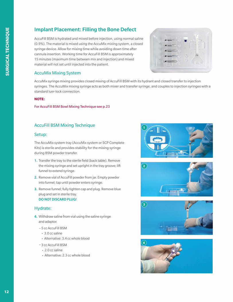
Implant Placement: Filling the Bone Defect
AccuFill BSM is hydrated and mixed before injection, using normal saline
(0.9%). The material is mixed using the AccuMix mixing system, a closed
syringe device. Allow for mixing time while avoiding down time after
cannula insertion. Working time for AccuFill BSM is approximately
15 minutes (maximum time between mix and injection) and mixed
material will not set until injected into the patient.
AccuMix Mixing System
AccuMix syringe mixing provides closed mixing of AccuFill BSM with its hydrant and closed transfer to injection
syringes. The AccuMix mixing syringe acts as both mixer and transfer syringe, and couples to injection syringes with a
standard luer-lock connection.
NOTE:
For AccuFill BSM Bowl Mixing Technique see p.23
1
2
3
4
AccuFill BSM Mixing Technique
Setup:
The AccuMix system tray (AccuMix system or SCP Complete
Kits) is sterile and provides stability for the mixing syringe
during BSM powder transfer.
1. Transfer the tray to the sterile field (back table). Remove
the mixing syringe and set upright in the tray groove; lift
funnel to extend syringe.
2. Remove vial of AccuFill powder from jar. Empty powder
into funnel; tap until powder enters syringe.
3. Remove funnel; fully tighten cap and plug. Remove blue
plug and set in sterile tray.
DO NOT DISCARD PLUG!
Hydrate:
4. Withdraw saline from vial using the saline syringe
and adaptor.
– 5 cc AccuFill BSM
• 3.0 cc saline
• Alternative: 3.4 cc whole blood
– 3 cc AccuFill BSM
• 2.0 cc saline
• Alternative: 2.3 cc whole blood
12 13
SUR
GIC
AL TEC
HN
IQU
E
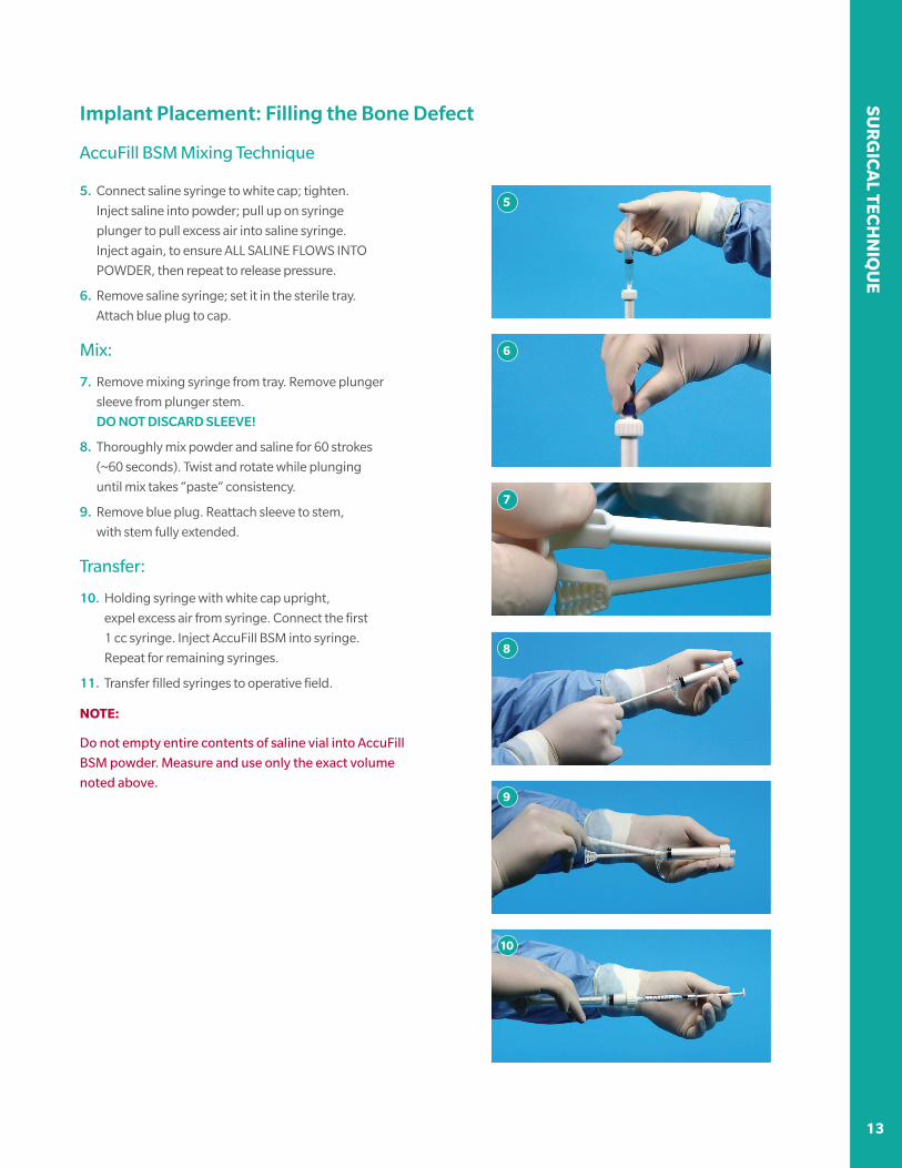
5. Connect saline syringe to white cap; tighten.
Inject saline into powder; pull up on syringe
plunger to pull excess air into saline syringe.
Inject again, to ensure ALL SALINE FLOWS INTO
POWDER, then repeat to release pressure.
6. Remove saline syringe; set it in the sterile tray.
Attach blue plug to cap.
Mix:
7. Remove mixing syringe from tray. Remove plunger
sleeve from plunger stem.
DO NOT DISCARD SLEEVE!
8. Thoroughly mix powder and saline for 60 strokes
(~60 seconds). Twist and rotate while plunging
until mix takes “paste” consistency.
9. Remove blue plug. Reattach sleeve to stem,
with stem fully extended.
Transfer:
10. Holding syringe with white cap upright,
expel excess air from syringe. Connect the first
1 cc syringe. Inject AccuFill BSM into syringe.
Repeat for remaining syringes.
11. Transfer filled syringes to operative field.
NOTE:
Do not empty entire contents of saline vial into AccuFill
BSM powder. Measure and use only the exact volume
noted above.
5
6
7
8
9
10
Implant Placement: Filling the Bone Defect
AccuFill BSM Mixing Technique

SUR
GIC
AL
TEC
HN
IQU
E
14 15
Implant Placement: Filling the Bone Defect
Injecting AccuFill BSM
• Confirm cannula position using AP and lateral fluoroscopy. When using a side-delivery cannula, manually rotate the
cannula to direct flow toward the defect, as indicated by the white line.
• Remove the inner stylus while holding the cannula body securely with one hand, squeeze together the adaptor locking
wings with the other hand, and pull the stylus out.
• Set the stylus on the sterile field (Mayo stand or back table). DO NOT DISCARD!
• Attach the first 1cc syringe of AccuFill mix to the cannula hub; firmly tighten the luer lock connector.
• Inject AccuFill BSM using steady manual pressure.
Remove stylus from cannula; Inject desired volume of AccuFill BSM
14 15
SUR
GIC
AL TEC
HN
IQU
E
Implant Placement: Filling the Bone Defect
Injecting AccuFill BSM
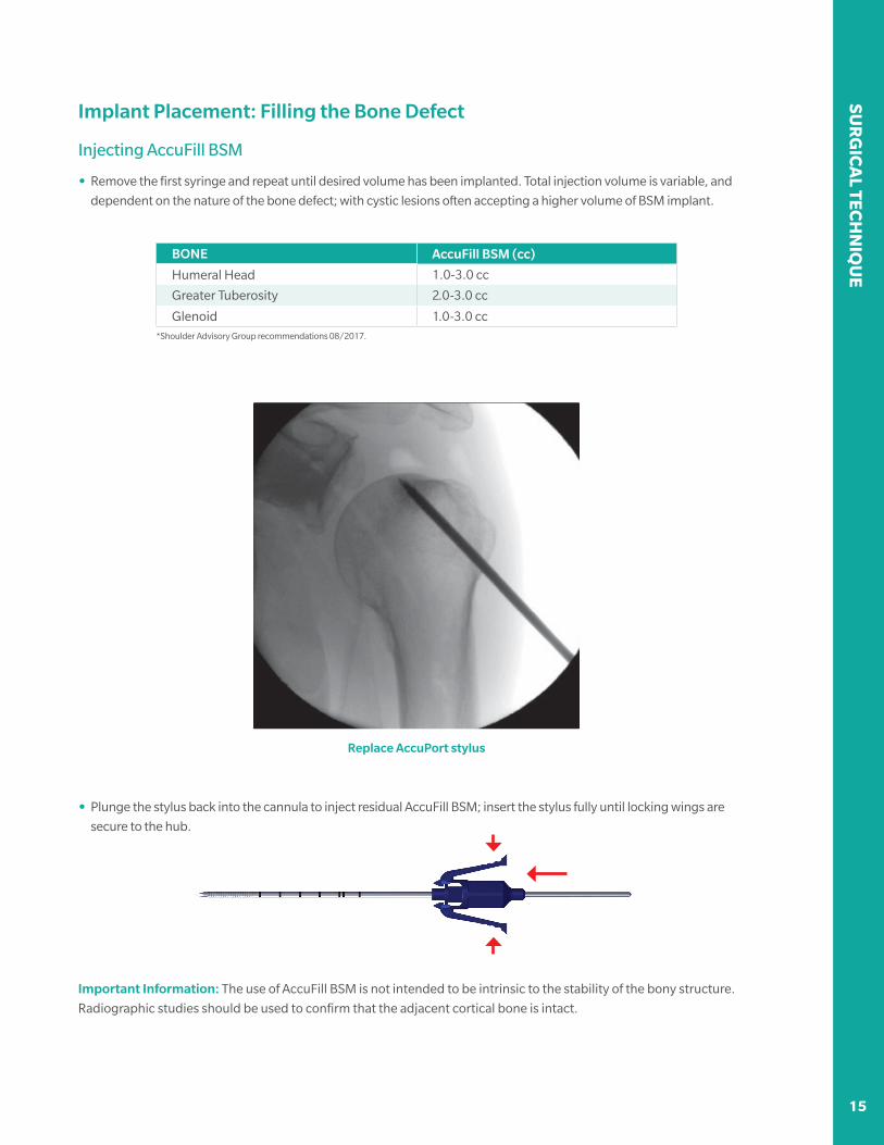
• Remove the first syringe and repeat until desired volume has been implanted. Total injection volume is variable, and
dependent on the nature of the bone defect; with cystic lesions often accepting a higher volume of BSM implant.
BONE AccuFill BSM (cc)
Humeral Head 1.0-3.0 cc
Greater Tuberosity 2.0-3.0 cc
Glenoid 1.0-3.0 cc *Shoulder Advisory Group recommendations 08/2017.
Replace AccuPort stylus
• Plunge the stylus back into the cannula to inject residual AccuFill BSM; insert the stylus fully until locking wings are
secure to the hub.
Important Information: The use of AccuFill BSM is not intended to be intrinsic to the stability of the bony structure.
Radiographic studies should be used to confirm that the adjacent cortical bone is intact.
SUR
GIC
AL
TEC
HN
IQU
E
16 17
NOTE:
• When attaching and removing 1 cc syringes from the cannula, grip the hub firmly to avoid rotating
the cannula.
• Do not overfill the defect site. Overpressurizing the device may lead to extrusion beyond the site of intended
application and damage to surrounding tissues. Remove any excess material from the subcutaneous tissue at the entry
point by gently expressing and irrigating the material. Blot any excess material from the surgical wound as needed.
• The cannula and stylus should be left in the bone for 10 minutes, while the AccuFill BSM hardens, to minimize
potential for extravasation of material.
• Allow AccuFill BSM to fully set prior to performing additional procedures such as anchor drilling.
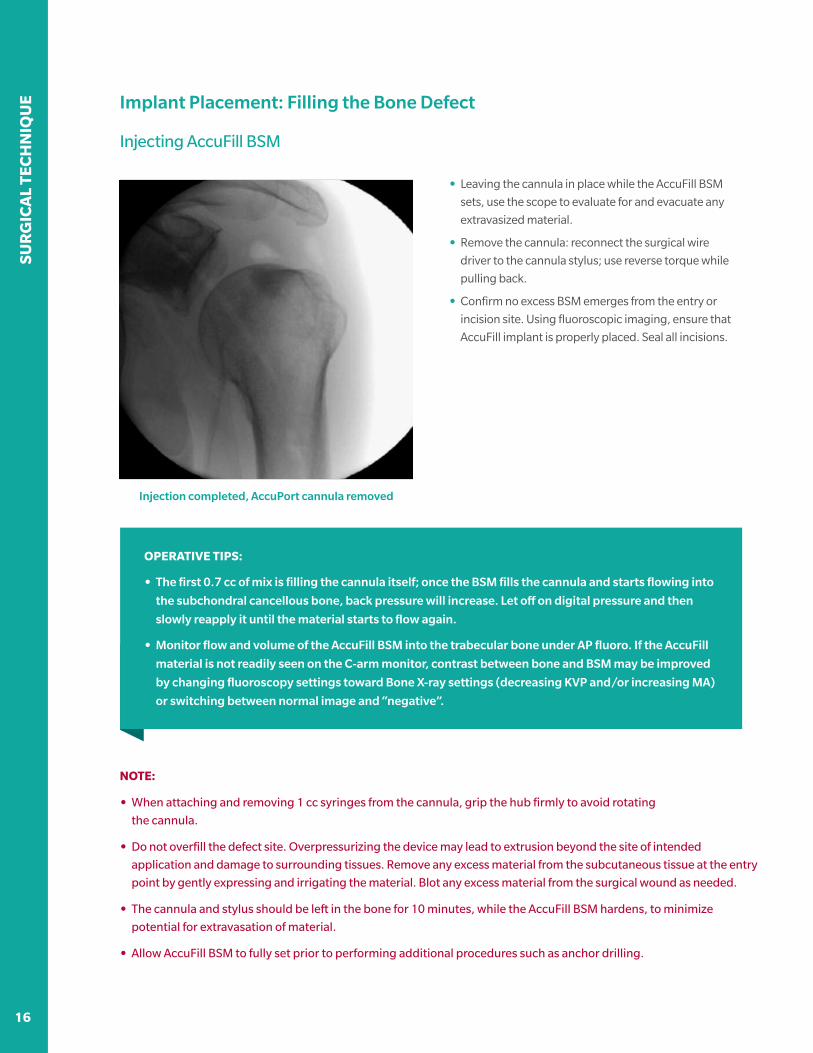
• Leaving the cannula in place while the AccuFill BSM
sets, use the scope to evaluate for and evacuate any
extravasized material.
• Remove the cannula: reconnect the surgical wire
driver to the cannula stylus; use reverse torque while
pulling back.
• Confirm no excess BSM emerges from the entry or
incision site. Using fluoroscopic imaging, ensure that
AccuFill implant is properly placed. Seal all incisions.
Injection completed, AccuPort cannula removed
OPERATIVE TIPS:
• The first 0.7 cc of mix is filling the cannula itself; once the BSM fills the cannula and starts flowing into
the subchondral cancellous bone, back pressure will increase. Let off on digital pressure and then
slowly reapply it until the material starts to flow again.
• Monitor flow and volume of the AccuFill BSM into the trabecular bone under AP fluoro. If the AccuFill
material is not readily seen on the C-arm monitor, contrast between bone and BSM may be improved
by changing fluoroscopy settings toward Bone X-ray settings (decreasing KVP and/or increasing MA)
or switching between normal image and “negative”.
Implant Placement: Filling the Bone Defect
Injecting AccuFill BSM

16 17
SUR
GIC
AL TEC
HN
IQU
E
Considerations for: Greater Tuberosity Defects
Two types of approach are used to access bony defects in the greater tuberosity: a direct lateral approach and a
medial footprint approach. In the lateral approach, the AccuPort cannula enters the greater tuberosity from directly
lateral, under fluoroscopic guidance to target the defect. In the medial footprint approach, the cannula entry point is
determined under guidance of the scope, at an approach typically used for medial row anchors, fluoroscopy is then
used to monitor drilling depth in the bone.
Direct Lateral Approach
Cannula at desired drill depth Fluoroscopically monitor implant flow
Medial Footprint Approach
Arthroscopically find cannula entry point Medial footprint approach to access bone defect
SUR
GIC
AL
TEC
HN
IQU
E
18 19
Considerations for: Glenoid Defects
Glenoid bone defects are often cystic in nature, and may or may not include associated BML bone defects.
When targeting these lesions, the SCP procedure is used to fill both the cyst and, if applicable, the surrounding
microtrabecular fracture. Two approaches to accessing bone defects are used in the glenoid: a scope-assisted rim
approach, or a joint-parallel approach. Due to the complex geometry of the glenoid and scapular neck, free-hand
targeting of these defects is technically challenging, with both approaches relying heavily on arthroscopic and/or
fluoroscopic assistance.
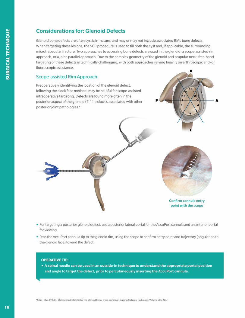
Scope-assisted Rim Approach
Preoperatively identifying the location of the glenoid defect,
following the clock face method, may be helpful for scope-assisted
intraoperative targeting. Defects are found more often in the
posterior aspect of the glenoid (7-11 o’clock), associated with other
posterior joint pathologies.*
• For targeting a posterior glenoid defect, use a posterior lateral portal for the AccuPort cannula and an anterior portal
for viewing.
• Pass the AccuPort cannula tip to the glenoid rim, using the scope to confirm entry point and trajectory (angulation to
the glenoid face) toward the defect.
OPERATIVE TIP:
• A spinal needle can be used in an outside-in technique to understand the appropriate portal position
and angle to target the defect, prior to percutaneously inserting the AccuPort cannula.
*S Yu, J et al. (1998). Osteochondral defect of the glenoid fossa: cross-sectional imaging features. Radiology. Volume 206, No. 1.
Confirm cannula entry point with the scope
18 19
SUR
GIC
AL TEC
HN
IQU
E
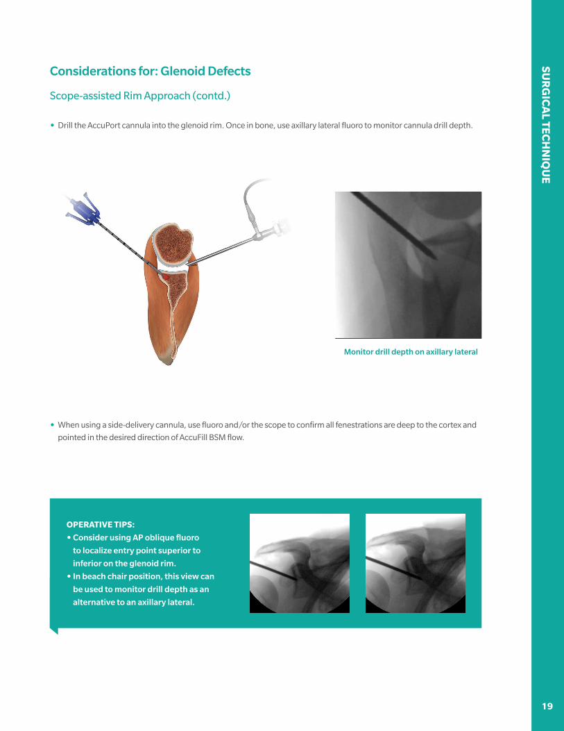
Considerations for: Glenoid Defects
Scope-assisted Rim Approach (contd.)
• When using a side-delivery cannula, use fluoro and/or the scope to confirm all fenestrations are deep to the cortex and
pointed in the desired direction of AccuFill BSM flow.
• Drill the AccuPort cannula into the glenoid rim. Once in bone, use axillary lateral fluoro to monitor cannula drill depth.
Monitor drill depth on axillary lateral
OPERATIVE TIPS:
• Consider using AP oblique fluoro
to localize entry point superior to
inferior on the glenoid rim.
• In beach chair position, this view can
be used to monitor drill depth as an
alternative to an axillary lateral.
SUR
GIC
AL
TEC
HN
IQU
E
20 21
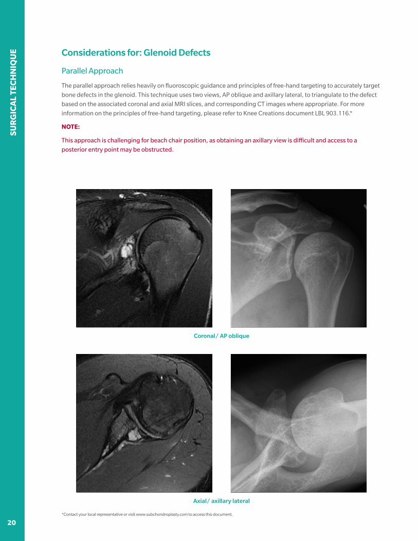
Considerations for: Glenoid Defects
Parallel Approach
The parallel approach relies heavily on fluoroscopic guidance and principles of free-hand targeting to accurately target
bone defects in the glenoid. This technique uses two views, AP oblique and axillary lateral, to triangulate to the defect
based on the associated coronal and axial MRI slices, and corresponding CT images where appropriate. For more
information on the principles of free-hand targeting, please refer to Knee Creations document LBL 903.116.*
NOTE:
This approach is challenging for beach chair position, as obtaining an axillary view is difficult and access to a
posterior entry point may be obstructed.
Coronal/ AP oblique
Axial/ axillary lateral
*Contact your local representative or visit www.subchondroplasty.com to access this document.
20 21
SUR
GIC
AL TEC
HN
IQU
E
Considerations for: Glenoid Defects
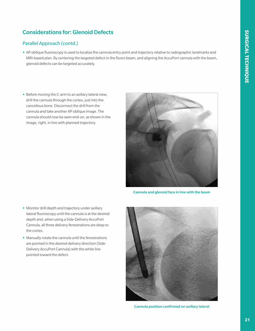
Parallel Approach (contd.)
• AP oblique fluoroscopy is used to localize the cannula entry point and trajectory relative to radiographic landmarks and
MRI-based plan. By centering the targeted defect in the fluoro beam, and aligning the AccuPort cannula with the beam,
glenoid defects can be targeted accurately.
• Before moving the C-arm to an axillary lateral view,
drill the cannula through the cortex, just into the
cancellous bone. Disconnect the drill from the
cannula and take another AP oblique image. The
cannula should now be seen end-on, as shown in the
image, right, in line with planned trajectory.
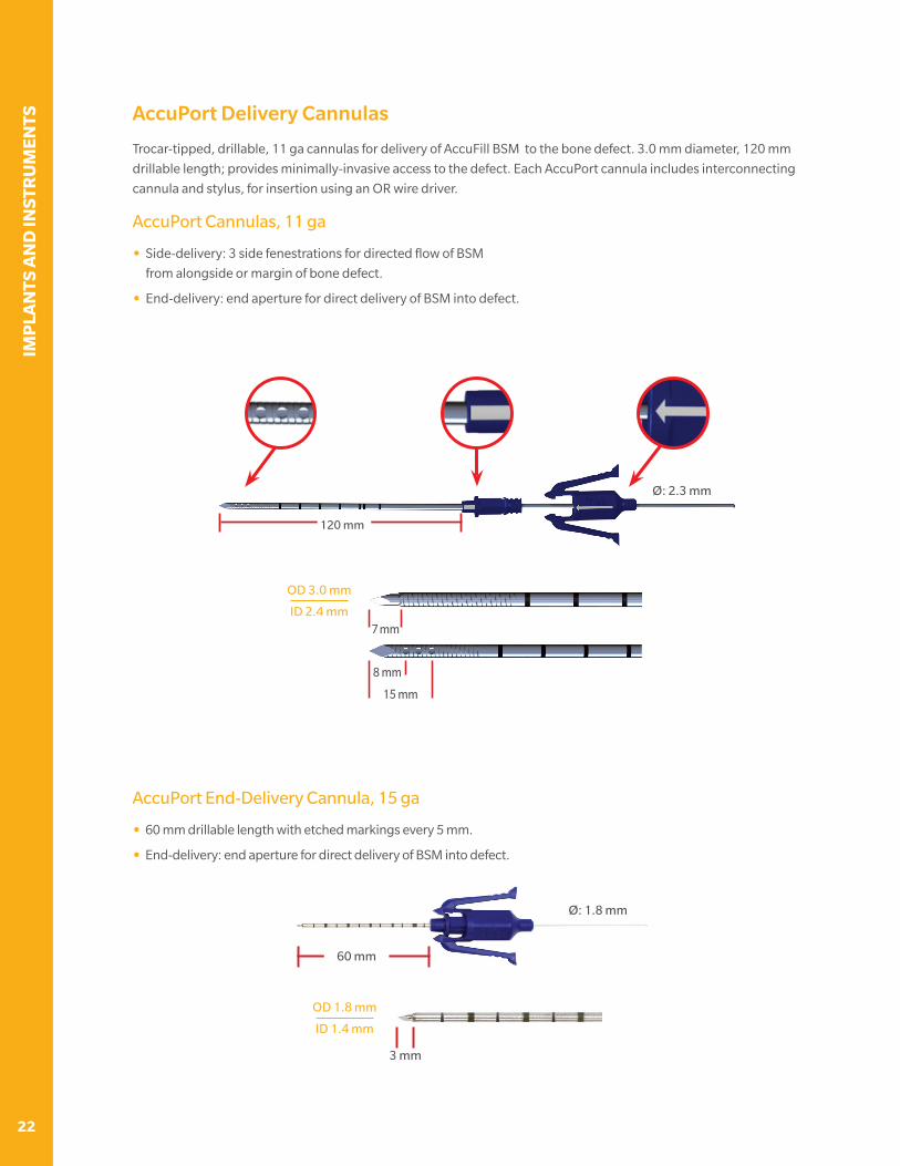
• Monitor drill depth and trajectory under axillary
lateral fluoroscopy until the cannula is at the desired
depth and, when using a Side-Delivery AccuPort
Cannula, all three delivery fenestrations are deep to
the cortex.
• Manually rotate the cannula until the fenestrations
are pointed in the desired delivery direction (Side-
Delivery AccuPort Cannula) with the white line
pointed toward the defect.
Cannula and glenoid face in line with the beam
Cannula position confirmed on axillary lateral
IMP
LAN
TS A
ND
INST
RU
MEN
TS
22
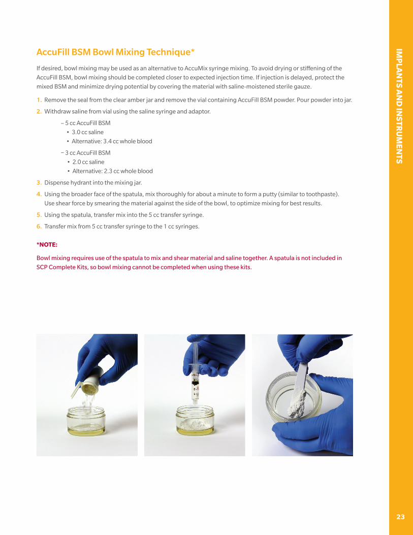
AccuPort Delivery Cannulas
Trocar-tipped, drillable, 11 ga cannulas for delivery of AccuFill BSM to the bone defect. 3.0 mm diameter, 120 mm
drillable length; provides minimally-invasive access to the defect. Each AccuPort cannula includes interconnecting
cannula and stylus, for insertion using an OR wire driver.
AccuPort Cannulas, 11 ga
• Side-delivery: 3 side fenestrations for directed flow of BSM
from alongside or margin of bone defect.
• End-delivery: end aperture for direct delivery of BSM into defect.
OD 3.0 mm
ID 2.4 mm7 mm
8 mm
15 mm
Ø: 2.3 mm
120 mm
AccuPort End-Delivery Cannula, 15 ga
• 60 mm drillable length with etched markings every 5 mm.
• End-delivery: end aperture for direct delivery of BSM into defect.
60 mm
Ø: 1.8 mm
3 mm
OD 1.8 mm
ID 1.4 mm
23
IMP
LAN
TS AN
D IN
STRU
MEN
TS
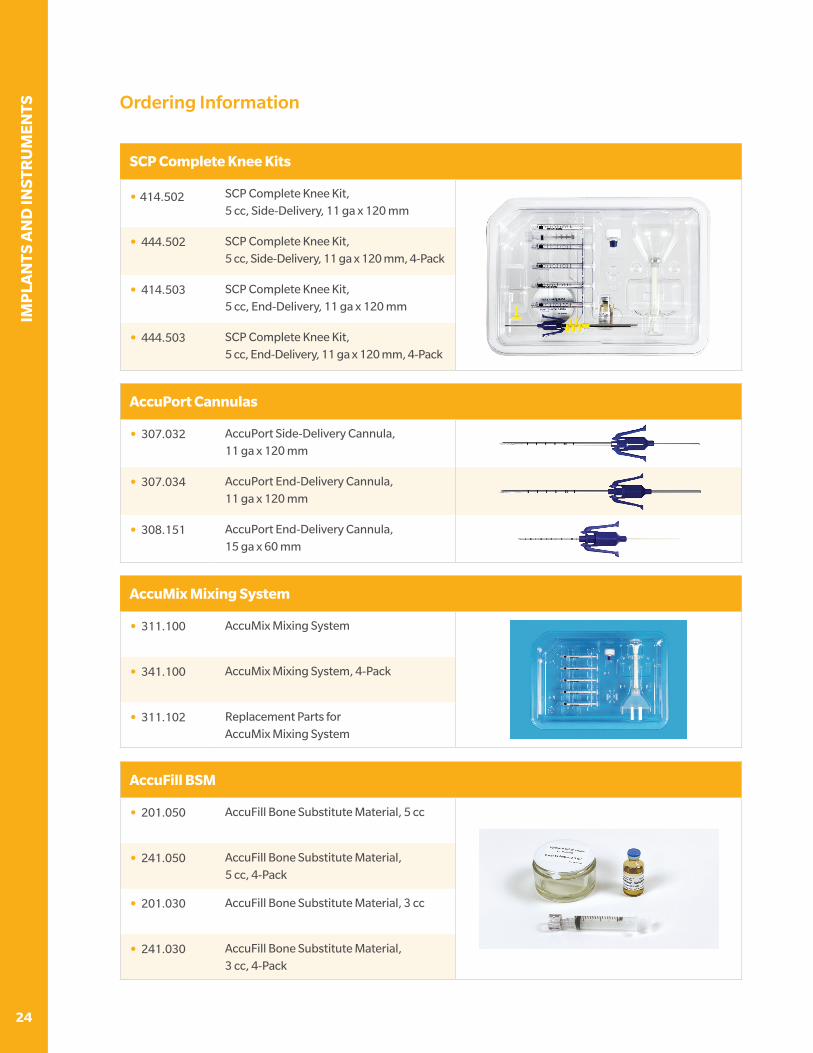
AccuFill BSM Bowl Mixing Technique*
If desired, bowl mixing may be used as an alternative to AccuMix syringe mixing. To avoid drying or stiffening of the
AccuFill BSM, bowl mixing should be completed closer to expected injection time. If injection is delayed, protect the
mixed BSM and minimize drying potential by covering the material with saline-moistened sterile gauze.
1. Remove the seal from the clear amber jar and remove the vial containing AccuFill BSM powder. Pour powder into jar.
2. Withdraw saline from vial using the saline syringe and adaptor.
– 5 cc AccuFill BSM
• 3.0 cc saline
• Alternative: 3.4 cc whole blood
– 3 cc AccuFill BSM
• 2.0 cc saline
• Alternative: 2.3 cc whole blood
3. Dispense hydrant into the mixing jar.
4. Using the broader face of the spatula, mix thoroughly for about a minute to form a putty (similar to toothpaste).
Use shear force by smearing the material against the side of the bowl, to optimize mixing for best results.
5. Using the spatula, transfer mix into the 5 cc transfer syringe.
6. Transfer mix from 5 cc transfer syringe to the 1 cc syringes.
*NOTE:
Bowl mixing requires use of the spatula to mix and shear material and saline together. A spatula is not included in
SCP Complete Kits, so bowl mixing cannot be completed when using these kits.
IMP
LAN
TS A
ND
INST
RU
MEN
TS
24
Ordering Information
AccuFill BSM
• 201.050 AccuFill Bone Substitute Material, 5 cc
• 241.050 AccuFill Bone Substitute Material, 5 cc, 4-Pack
• 201.030 AccuFill Bone Substitute Material, 3 cc
• 241.030 AccuFill Bone Substitute Material, 3 cc, 4-Pack
SCP Complete Knee Kits
• 414.502 SCP Complete Knee Kit, 5 cc, Side-Delivery, 11 ga x 120 mm
• 444.502 SCP Complete Knee Kit, 5 cc, Side-Delivery, 11 ga x 120 mm, 4-Pack
• 414.503 SCP Complete Knee Kit, 5 cc, End-Delivery, 11 ga x 120 mm
• 444.503 SCP Complete Knee Kit, 5 cc, End-Delivery, 11 ga x 120 mm, 4-Pack
AccuMix Mixing System
• 311.100 AccuMix Mixing System
• 341.100 AccuMix Mixing System, 4-Pack
• 311.102 Replacement Parts for AccuMix Mixing System
AccuPort Cannulas
• 307.032 AccuPort Side-Delivery Cannula, 11 ga x 120 mm
• 307.034 AccuPort End-Delivery Cannula, 11 ga x 120 mm
• 308.151 AccuPort End-Delivery Cannula, 15 ga x 60 mm
25
IMP
LAN
TS AN
D IN
STRU
MEN
TS
Notes:

IMP
LAN
TS A
ND
INST
RU
MEN
TS
26
Notes:

27
IMP
LAN
TS AN
D IN
STRU
MEN
TS
Notes:
All content herein is protected by copyright, trademarks and other
intellectual property rights, as applicable, owned by or licensed to
Zimmer Biomet or its affiliates unless otherwise indicated, and must
not be redistributed, duplicated or disclosed, in whole or in part,
without the express written consent of Zimmer Biomet.
This material is intended for health care professionals. Distribution to
any other recipient is prohibited.
For product indications, contraindications, warnings, precautions,
potential adverse effects and patient counseling information,
see the package insert or contact your local representative;
visit www.zimmerbiomet.com for additional product information.
Zimmer Biomet does not practice medicine. This technique was
developed in conjunction with a health care professional.
This document is intended for surgeons and is not intended for
laypersons. Each surgeon should exercise his or her own independent
judgment in the diagnosis and treatment of an individual patient, and
this information does not purport to replace the comprehensive training
surgeons have received. As with all surgical procedures, the technique
used in each case will depend on the surgeon’s medical judgment as
the best treatment for each patient. Results will vary based on health,
weight, activity and other variables. Not all patients are candidates for
this product and/or procedure. Caution: Federal (USA) law restricts this
device to sale by or on the order of a surgeon. Rx only.
©2018 Zimmer Biomet
MANUFACTURERZimmer Knee Creations841 Springdale DriveExton, PA 19341USA
AccuFill BSM MANUFACTURED BY:ETEX Corporation38 Sidney Street,Cambridge, MA 02139USA
subchondroplasty.com1-855-727-5818 | [email protected]
LBL 903.118 Rev A | Copyright © 2018 Zimmer Knee Creations, Inc.


