Computer-based systems on ships and offshore vessels: The Software Problem ++ Marine Cybernetics Det Norske Veritas Statoil Kongsberg Maritime Smedvig Smedvig Offshore Norsk Hydro Stolt Offshore Eidesvik Shipping Solstad Offshore Subsea 7 Ulstein ABB INTERNAL
Transcript
Computer-based systems on ships and offshore vessels:
The Software Problem ++
Marine Cybernetics
Det Norske Veritas
Statoil
Kongsberg Maritime
Smedvig
Smedvig Offshore
Norsk Hydro
Stolt Offshore
Eidesvik Shipping
Solstad Offshore
Subsea 7
Ulstein
ABB
INTERNAL
The Software Problem ++ Page 2
Preface This document is prepared by Marine Cybernetics (Roger Skjetne and Asgeir Sørensen) and based on contributions from all companies in the sponsor reference group. The contents of the document are the sole responsibility of Marine Cybernetics, and the views, assessments, and conclusions presented are not necessarily representative for the other contributing parties in the project.
We acknowledge special contributions and comments from DNV (Aleks Karlsen and Stian Ruud), Smedvig Offshore (Harry Verhoeven), Kongsberg Maritime (Bjørn Gjelstad and Nils A. Jenssen), and Statoil (Ole J. Nordahl and Kjell Larsen).
Sponsors and reference group in the project: Marine Cybernetics DNV Statoil Smedvig Offshore Kongsberg Maritime Norsk Hydro Stolt Offshore Eidesvik Subsea 7 Solstad Offshore Ulstein ABB Petroleum Safety Authority Norway Norwegian Maritime Directorate
Trondheim, 2004-10-27
Reference: Reference to part of this report which may lead to misinterpretation is not permissible.
Disclaimers The information contained in this document is the proprietary and exclusive property of Marine Cybernetics and the companies indicated by name and logo on the title page, called hereafter the “contributing companies”. No part of this document, in whole or part, may be reproduced, stored, transmitted, or used without prior written permission of Marine Cybernetics.
The information in this document is subject to change without notice.
The information in this document is provided for informational purposes only. Any or all errors in writing or failures of any kind in the document or information given in the document can not in any matter be any ground for responsibility or liability whatsoever for Marine Cybernetics or any other contributor. The contributing companies specifically disclaim all warranties, express or limited, including, but not limited to, the implied warranties of merchantability and fitness for a particular purpose.
Non disclosure This document may contain information of a sensitive nature. This information should not be given to persons other than those involved in the project, or who will be involved during the document lifecycle.
Breach of obligations of non disclosure or other infringements or violation of the contributing companies’ rights or privileges, included patents, involves liability.
Version history
Revision chart
Version Author(s) Description of version Date completed
1.0 Marine Cybernetics with contributions from DNV, Smedvig Offshore, Statoil, and Kongsberg Maritime
Completed in connection with sea trials in the pilot project CyberSea Simulator.
1.2 Purpose and future application ...................................................................................................................................... 7
1.3 Trends for computer-based systems .............................................................................................................................. 8
2.1 Examples of IMCA reported incidents........................................................................................................................ 11
2.2 Examples of contractor reported incidents................................................................................................................. 17
2.3 Examples of Statoil reported incidents........................................................................................................................ 18
2.4 Potential consequences related to DP incidents.......................................................................................................... 21
3 WHAT IS THE SOFTWARE PROBLEM ++?..................................................................................................22
3.1 Computer-based systems on ships and offshore vessels............................................................................................ 22
3.2 Drivers for technology progress.................................................................................................................................... 26
3.3 Practice for quality assurance in maritime industry................................................................................................. 26
3.4 Observations and problems related to computer-based control and monitoring systems .................................. 33
Executive Summary This report deals with the imprecise term denoted ‘software problems’ for control and monitoring systems onboard ships and offshore vessels. It has, however, turned out that many problems identified are not purely related to the software, but are related to design, fabrication, operation, and maintenance of the systems. Due to this fact we have denoted all these related problems as the ‘Software Problem ++’.
In order to understand why software problems occur, this report gives a brief description of the main drivers for technology progress, leading to an increasing integration complexity and number of I/O for industrial control and monitoring systems for offshore vessels. Moreover, state of practice for quality assurance (QA) is briefly treated in order to evaluate the effectiveness of present QA procedures for capturing the described problems. Examples in the report are taken from incidents related to failures in computer-based systems onboard DP vessels. The main focus has therefore been problems related to DP systems, but it is anticipated that most of the problems reported will also be found in other computer-based systems.
This report should form the basis for evaluation of possible solutions to the challenges identified. The next step should be to identify the most promising solutions and how these solutions actually will solve the various challenges identified in the 'Software problem++'.
The Software Problem ++ Page 6
References
[1] IMO, “Guidelines for Vessels with Dynamic Positioning Systems,” MSC/Circ.645, June 6, 1994.
[2] IMCA, “Guidelines for The Design & Operation of Dynamically Positioned Vessels,” IMCA M 103, February 1999.
[3] DNV Rules for classification of Ships / High Speed, Light Craft and Naval Surface Craft, Pt. 4, Ch. 8, “Electrical Installations,” January 2004.
[4] DNV Rules for classification of Ships / High Speed, Light Craft and Naval Surface Craft, Pt. 4, Ch. 9, “Control and Monitoring Systems,” January 2004.
[5] DNV Rules for classification of Ships, Pt. 6, Ch. 7, “Dynamic Positioning Systems,” January 2004.
[6] DNV Rules for classification of Ships, Pt. 6, Ch. 8, “Nautical Safety,” January 2003.
[7] Statoil, “DP Requirements for Drilling and Intervention Units,” Report TR 1029, September 1, 2002.
[8] Scandpower Risk Management AS, “Safety of Dynamic Positioning Operation on Mobile Offshore Drilling Units,” Report no. 27.790.044/R1, March 24, 2004.
[10] IMCA, “Dynamic Positioning Station Keeping Incidents: Incidents reported for 2000,” IMCA M 165, December 2001.
[11] IMCA, “Station Keeping Incidents Reported for 2001,” IMCA M 169, February 2003.
[12] Rensvik, E., A. J. Sørensen, and M. Rasmussen, “Maritime Industrial IT,” Proc. 9th Int. conf. Marine Eng. Systems (ICMES), Helsinki, Finland, May 19-21, 2003.
[13] Sørensen, A. J., “Marine Cybernetics: Modelling and Control,” Lecture notes, Report UK-04-76, Dept. Marine Technology, NTNU, Trondheim, Norway, 2004.
[14] Norsk Hydro, “DP Unit requirements for drilling/well intervention units,” Internal report, 2003-06-21.
[15] Norske Shell, “DP drilling unit requirements.”
[16] IMCA, “Guidance on Failure Modes & Effects Analyses (FMEAs),” IMCA M 166, April 2002.
The Software Problem ++ Page 7
1 Introduction
1.1 Objective This document describes important aspects and problems related to safety-critical control and monitoring systems onboard ships and offshore vessels. By a computer-based system we mean a complex system [4] consisting of one or several integrated computers performing a number of specified autonomous function related to control and/or monitoring of vessel processes. Such systems perform their function as an interaction between the vessel, the sensors, the actuators, the computer hardware (HW), the software (SW), and the operators. The operation of the systems itself, or a failure during operation of the systems may potentially become harmful to life, property, or the environment.
The focus in this document is on the SW and its interaction with HW and the human operator in computer-based systems onboard marine vessels. The main objective is to identify various types of SW problems. To do so we consider the increasing complexity of computer-based systems for marine vessels and the drivers for such technology development in order to understand why the problems arise. Then, the state of practice in maritime industry for quality assurance (QA) throughout the lifecycle of a computer-based system is described to understand why some general types of problems are very often not revealed. DP incident reports are used as examples in order to document actual problems.
1.2 Purpose and future application This document is a first description of challenges related to the so called “Software Problem”. The purpose of this document is to be applied as a basis for selection of measures for improving the quality assurance and the safety of software-based control and monitoring systems.
In 2003-2004 Marine Cybernetics, in cooperation with DNV, oil companies, vendors, ship operators and contractors, and yards, developed a service offering Hardware-In-the-Loop (HIL) testing of marine control and monitoring systems. In 2004 DNV published new rules for Control and monitoring systems in ships including additional requirements to computers and software. Other companies are also proposing different services for improving the quality assurance of such systems. However, each of the above initiatives will address some of the challenges identified.
The intention is that when the ‘Software Problem ++’ document has been established, it will be easier to evaluate proposed quality assurance measures available, and then identify an optimal set of future measures to be recommended.
This version of the document should not be considered to cover all aspects of the “Software Problem”.
The document is intended for use by system suppliers, manufacturers, yards, designers, ship owners and operators, suppliers of quality assurance services, consultants, and classification societies.
The Software Problem ++ Page 8
1.3 Trends for computer-based systems As the technology evolves, HW and SW driven systems are getting more and more advanced. The following characteristics and trends are observed for computer-based systems for ships and offshore vessels:
Technology:
The dependence and importance of computer-based systems are increasing. The share of SW in computer-based systems is increasing. The level of integration and system complexity is increasing. Low-cost Commercial Off The Shelf (COTS) technology, originally developed for the office
and consumer market, is emerging into safety-critical applications. More “black-box” components and complex interactions between HW, SW, and the human
operator. Quality of SW is variable. System design and SW manufacturing is often done by IT-
engineers, who may not have system, and/or safety engineering, and/or application understanding.
Functional redundancy relies not only on redundant HW components; it depends strongly on the implementation of redundancy functions in the SW.
The consequences of SW failures increase. Multiple failures and sequences of failures, involving a combination of HW, SW, and human
interactions, result in incidents and accidents.
Cost:
Always a drive for bigger, better, faster, and cheaper system technologies. Control and monitoring systems are a significant and increasing part of costs in new vessels
and offshore installations. Low-cost solutions are often given priority in decision criteria for contract awards. On the other hand; the consequences of failures of such computer-based systems can be
significant in cost. For instance, typical day-rates for advanced offshore vessels are in the order of 1-3 MNOK, including operator and client cost. Hence, quality problems and cost in the North Sea related to failures in computer-based systems onboard marine vessels result annually in a direct cost of several 10xMNOK. The consequential cost related to off-hire and loss of production is substantially higher.
QA procedures and testing:
Adequate quality of functions implemented in SW depends to a great extent on sufficient functional testing.
Marine testing and certification methodology have so far had its main focus on structures and machinery.
Development of sufficient testing and verification methodologies for computer-based systems is a concern.
Testing and certification has historically targeted single-point failures in system components. Partly as a result of this, incidents today are often caused by scenarios of multiple failures.
The Software Problem ++ Page 9
Insufficient documentation quality. Insufficient requirement specification and analysis. Insufficient in-house QA procedures. Lack of QA for reconfiguration and reprogramming
during installation, commissioning, testing, and after delivery. Insufficient revision control of upgrades. Lack of tools for QA, verification and validation of SW safety and performance; in particular,
testing of the integrated HW and SW embedded in real environmental conditions.
The Software Problem ++ Page 10
2 DP incidents The success (or perhaps failure?) of present industry practices for testing safety-critical computer-based systems can be measured in the number of incidents for such systems. For Dynamic Positioning (DP) systems a collection of approximately 40-100 incidents are reported each year, 1990−2001, to IMCA on the basis that the vessel name, owner, and client are kept confidential. The reporting of such incidents is believed to be the tip of an iceberg, meaning that a large amount of incidents are not reported for various reasons.
DP incident trends of IMCA from 1990−2001 [11] indicates an increasing number of incidents with primary cause in computer related problems, and several of these incidents have “insufficient testing/commissioning or QA” as a secondary cause. “No simple explanation is available other than the obvious, that generally vessels have more computers with integrated control systems” [11].
Another interesting point made by IMCA in [11] is that “Computer hardware problems cause downtime and generally not position loss (at least not alone) whereas computer software causes position loss.” It is further commented that “this is to be expected since hardware is redundant but the software is not.”
The IMCA reported incidents [10,11] are classified in terms of consequences as follows:
Loss of position 1 – major consequences.
Loss of position 2 – minor consequences.
Lost time incidents – loss of redundancy or downtime, but no loss of position.
The incidents reported by IMCA in 2000 and 2001 were categorized as follows:
Loss of position 1 Loss of position 2 Lost time incidents
2000 36 (33%) 41 (37%) 33 (30%)
2001 21 (21%) 34 (35%) 43 (44%)
Computers were according to IMCA [10,11] the primary cause in 19% of the incidents in 2000 and 33% in 2001 among Loss of position 1 incidents. The corresponding numbers for reference systems were 19% and 14%, thrusters caused 8% and 14%, while generators caused 14% and 10%, respectively.
Figure 1 shows trends for the primary causes of incidents in the 12 year period 1990-2001. The numbers are in percentage out of total reported incidents (Loss of position 1 & 2, and Lost time incidents) the respective years. The two main causes are “Computers” and “Reference systems”, where computers seem to have the most increasing trend.
Another trend is that operators are blamed less for incidents at the expense of technology or the environment. Perhaps an operator is not always capable of executing a preventive action, even if an alarm or warning has been issued. Consequently, the technology must do more, if possible, with the result of more software and thereby increased probability of SW-related failures. Nevertheless, the
The Software Problem ++ Page 11
importance of a well-designed human-machine interface (HMI), work station layout, and operational procedures are crucial to ensure proper failure handling.
Figure 1: Incident trends 1990-2001 for different primary cause failure groups. “Computers” and “Reference systems” are main causes. Operator errors seems to be decrasing.
2.1 Examples of IMCA reported incidents The following are typical SW-related incidents; see [10,11]. Note that when problems are said to be caused by the DP SW, this does not necessarily mean that a traditional SW failure (bug) is encountered. Rather it is often expected that the SW should handle the condition/situation.
No. 1.1 [10, Case 0002]: Loss of position 1
Events: Vessel on DP, moving to other side of platform, 2 DGPS + TW online Position move executed Heading change input DP “current” increasing, heading overshoot Position out-of-limits Yellow alert, TW at limit Divers recovered
Comment: The vessel was unable to make the heading change as expected and manual control was required to clear the platform. There was no fast current update facility, but there might have been thruster tuning problems. Main cause: Computer (DP software)
Vessel on DP 1300m, drilling operations, 2 DGPS + 2 HPR online 3+3 Diesel generators online, bus tie open Insufficient thrust alarm All thrusters not ready, yellow alert, manual control selected PLC comms error alarm Standby boat called, 24m drift off
Comment: This is the first stage in a series of problems over a period of several hours. DP was restored and the yellow alert cancelled. The root cause is unclear but the PLCs and the DP-control software were prime suspects for causing the thrusters to drop off the DP desk.
Main cause: Computer (DP software)
Secondary cause: Computer (DP hardware)
No. 1.3 [10, Case 0004]: Loss of position 1
Events:
Vessel on DP 1300m, drilling operations, 2 HPR online 3+3 Diesel generators online, bus tie closed, 4 thrusters online One thruster trips Drift off Thruster restored 6m but trips All thrusters lost to DP Manual mode, yellow alert, excursion increasing Red alert and Emergency disconnect
Comment: The problem was initially with one azimuth thruster; it was lost and restored many times. When all thrusters were lost there was some hope of manual recovery but this was not successful and the red alert was given when the position loss reached 50m.
Main cause: Computer (DP software)
Secondary cause: Computer (DP hardware)
The Software Problem ++ Page 13
No. 1.4 [10, Case 0007]: Loss of position 1
Events:
Vessel on DP in 830m, recovering lifting floats from pipeline, 2DGPS + HPR online Over manifold and <500m from FPSO Online computer freeze, no thrust commands, no alarms Position and heading changing, no Auto or Manual change-over possible Manual lever control Computer powered down, Auto change-over DP restored
Comment: This is a serious failure mode for [the DP] system as there are no alarms to give the operator a warning. The same has happened on other vessels and new software is available.
Vessel on DP in 100m, laying pipe, 2DGPS + 2 TWs online Position out-of-limits Prediction error on Thruster 6, prediction error on Thruster 1 Power limits reached Thrust reduced Bus 1, thrust reduced Bus 2 Pipe tension exceeds limits
Comment: At the end of pulling one pipe joint, the speed was too high and the overshoot caused the DP to respond, but the time to respond is a function of azimuth thruster rotation time. In shallow water this can cause instability. It is avoided by bias mode or avoiding the thrusters azimuth rotation. In this case the DPO failed to act correctly and/or fast enough.
Main cause: Computer (DP software)
Secondary cause: Operator error
The Software Problem ++ Page 14
No. 1.6 [11, Case 0105]: Loss of position 1
Events:
Vessel on DP close to rig, ROV survey of flex risers, 2 DGPS + 2 HPR online Alarm Computer B Auto change-over Computer A Bridge PLC link fail Computer A, drift-off position Manual control Moved clear of rig
Comment: Computer A would not reboot initially but Computer B rebooted successfully. The supplier of system was called as a software bug was suspected.
Main cause: Computer (DP software)
Secondary cause: Computer (DP hardware)
No. 1.7 [11, Case 0106]: Loss of position 1
Events:
Vessel on DP near platform, passing riser to platform, 3 DGPS online Online DP control A crashed No Auto change-over, Forced change-over to B DP control B crashed Manual control, reboot DP control A Vessel moved clear of platform
Comment: The vessel moved clear of platform to await the system supplier engineer. After the system supplier investigation it was found that only the graphics on console A had crashed and that the vessel was still on DP. In this state auto change-over would not take place. After the forced change-over the operator selected the ‘Motion Page’ and B crashed. The system supplier advised operators not to select the ‘Motion Page’ until the other console had been rebooted.
Main cause: Computer (DP software)
Secondary cause: Poor design
The Software Problem ++ Page 15
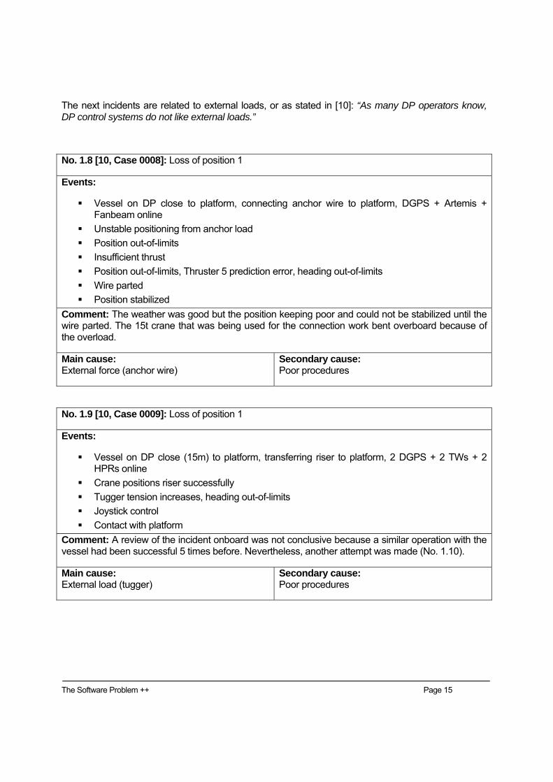
The next incidents are related to external loads, or as stated in [10]: “As many DP operators know, DP control systems do not like external loads.”
No. 1.8 [10, Case 0008]: Loss of position 1
Events:
Vessel on DP close to platform, connecting anchor wire to platform, DGPS + Artemis + Fanbeam online
Unstable positioning from anchor load Position out-of-limits Insufficient thrust Position out-of-limits, Thruster 5 prediction error, heading out-of-limits Wire parted Position stabilized
Comment: The weather was good but the position keeping poor and could not be stabilized until the wire parted. The 15t crane that was being used for the connection work bent overboard because of the overload.
Main cause: External force (anchor wire)
Secondary cause: Poor procedures
No. 1.9 [10, Case 0009]: Loss of position 1
Events:
Vessel on DP close (15m) to platform, transferring riser to platform, 2 DGPS + 2 TWs + 2 HPRs online
Crane positions riser successfully Tugger tension increases, heading out-of-limits Joystick control Contact with platform
Comment: A review of the incident onboard was not conclusive because a similar operation with the vessel had been successful 5 times before. Nevertheless, another attempt was made (No. 1.10).
Main cause: External load (tugger)
Secondary cause: Poor procedures
The Software Problem ++ Page 16
No. 1.10 [10, Case 0010]: Loss of position 1
Events:
Vessel on DP 20m from platform, transferring riser to platform, 2 DGPS + 2 TWs + HPR online
Crane positions riser satisfactory Vessel loosing heading 12 m from platform, joystick control Response inadequate Lever control Contact with platform
Comment: See also Case 0009. The quick current function was selected this time, but no difference was noticed, nor did high thrust develop until lever control was taken. The information provided does not close out this incident, but DP-control system do not like being “moored” to platforms. Nevertheless, for the heading to change and no rapid thrust to counter the yaw, point to a DP-control problem or an operator error.
Main cause: External load (tugger)
Secondary cause: Computer (DP software)
No. 1.11 [10, Case 0017]: Loss of position 1
Events:
Vessel on DP, ROV in water, 2 DGPS + 2 HPR online Heading out-of-limits Position out-of-limits High thrust demand, position unstable, high power demand Blackout Drift off
Comment: Vendor was called and so were the yard to find the cause. Software (model), position references, thrusters were all blamed, but no particular cause was established. The problem may have been introduced after dry-dock and not tuned and tested properly.
The drill ship was waiting on weather and in yellow status. The ship was hit by a series of consecutive large waves and forced off position. The rapid position deviation caused all DP position reference systems to be rejected by the DP controller based on prediction error. Prediction error indicates that deviation between the DP model and the DP position reference systems is beyond a predefined limit. The model went into dead reckoning mode as all DP position reference systems were rejected. Direct causes:
Acceptance limits for the prediction test was changed from “Normal = medium limit” to “Low = narrow limit” on earlier recommendation.
Acceptance limits for the prediction test should have been in “Normal”. Low acceptance limit is OK for low to moderate sea conditions. But not for high sea conditions
as those the drill ship experienced.
Case 2.2: Pipelay vessel
Short description of incident:
A complete DP control failure occurred on the Pipelay vessel on 4 July, 2002, while installing a 12” pipeline in the North Sea. The vessel was in AutoTrack mode, and stopped in the water while an anode was being fitted. The weather was good, with 17 knot wind and 1 m wave height. The vessel satisfied IMO DP equipment class 2. At 15:47 a communication network failed, causing complete failure of both DP computers and the bridge VMS. Thruster and engine controls were switched to manual, but although main engine and steering control were retained, all thruster control was lost. The vessel position was stabilized by 16:06, approximately 20 minutes after the incident started. During this period, the vessel had moved 350 m from the pipeline route. No damage was reported to the pipeline. Direct causes:
Failure in the DP communication network.
The Software Problem ++ Page 18
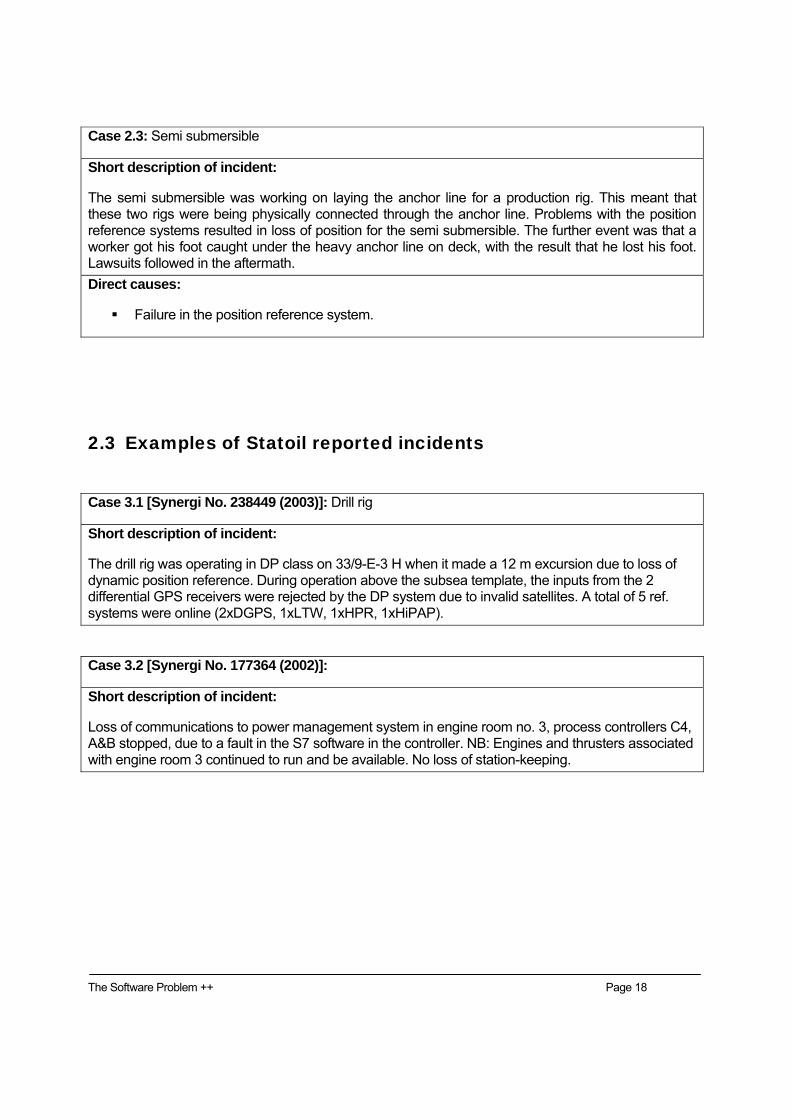
Case 2.3: Semi submersible
Short description of incident:
The semi submersible was working on laying the anchor line for a production rig. This meant that these two rigs were being physically connected through the anchor line. Problems with the position reference systems resulted in loss of position for the semi submersible. The further event was that a worker got his foot caught under the heavy anchor line on deck, with the result that he lost his foot. Lawsuits followed in the aftermath. Direct causes:
Failure in the position reference system.
2.3 Examples of Statoil reported incidents
Case 3.1 [Synergi No. 238449 (2003)]: Drill rig
Short description of incident:
The drill rig was operating in DP class on 33/9-E-3 H when it made a 12 m excursion due to loss of dynamic position reference. During operation above the subsea template, the inputs from the 2 differential GPS receivers were rejected by the DP system due to invalid satellites. A total of 5 ref. systems were online (2xDGPS, 1xLTW, 1xHPR, 1xHiPAP).
Case 3.2 [Synergi No. 177364 (2002)]:
Short description of incident:
Loss of communications to power management system in engine room no. 3, process controllers C4, A&B stopped, due to a fault in the S7 software in the controller. NB: Engines and thrusters associated with engine room 3 continued to run and be available. No loss of station-keeping.
The Software Problem ++ Page 19
Case 3.3 [Synergi No. 62689 (2000)]:
Short description of incident:
The vessel was performing bulk losing to the rig using 4 hoses. There was at the same time loaded cargo that was placed on the port side. Heading was 25 deg., and the vessel was located on the windward side. This was the only available side for the loading operation. In order for the crane to reach the ship port side, the vessel had to lie pretty close to the rig. At 11.30 hrs the operator got a power failure on the bow thruster, and this went over to “emergency on mode.” The forward azimuth thruster and both stern thrusters were still running. Alarm was signed off on the joystick panel, and normally one should still have control over 3 side thrusters. But there was no response from the joystick. The control was switched to manual, but there was still no response here. In the same time, emergency control was started on the bow thruster which still was in “emergency on mode.” No response here either. The main engines were intact, and maneuvering with the main propellers and rudders was initiated to move the vessel stern part away from the stern port column of the rig. In the meantime had the vessel starboard side touched the rig’s port “pencil column.” According to printout was the fault present for 28 sec. and then everything was back to normal, and the vessel moved quickly away from the rig. The joystick function was then also normal. The loading operation continued until everything was done and the hoses was returned at 12.00 hrs. Weather: Wind 15 knots WNW, Sea 4-5 m, heavy westerly swell.
Case 3.4 [Synergi No. 73456 (2000)]: Supply vessel
Short description of incident:
During setup to DP in order to check anchor positions relative to the pipeline, the port main propeller was unavailable to DP. Later in the day, the same propeller failed 4-5 times, but returned to operation by itself. Since the weather was good and the vessel was far away from any installation, the work was completed. Afterwards the DP system was restarted, and since then the fault has not occurred again.
Case 3.5 [Synergi No. 240190 (2003)]: Diving facility
Short description of incident:
Electronic monitoring system in sat. control and dive control not working due to software error. No loss or damage – and no divers in the chamber at the time of this report. The monitoring system will although be out of order for some time after the sat. has started.
The Software Problem ++ Page 20
Case 3.6 [Synergi No. 57086 (1999)]: MPSV
Short description of incident:
Finished at 15:51 to load “backload” by the Gullfaks A south side. Captain and the chief officer on bridge. Chief officer sat in DP chair with command. The ship was on DP with ref. systems DGPS 1 and Fanbeam. Heading was 205 deg. When the ship was about to leave the platform, a new position command of 5 m port was set in DP. Afterwards, DP was set to manual, and joystick was commanded forward. When there was no response, joystick was set to “high gain.” Since there was still no response from the joystick, the DP was set in Auto, and then the thrusters went out of control, and the ship was rapidly moving towards GFA. This even if the set-point was 10 m to port (away from platform). The captain took then control at the forward bridge desk, transferred to emergency control, and commanded forward on the main propellers. At the same time, the starboard chimney first and next the main mast hit GFA at the south-west corner, under living quarter. The collision was so powerful that the mast was hit off and fell on deck. Starboard chimney was squeezed so that it blocked the exhaust. Port chimney was also squeezed, probably caused by the mast. Stopped the starboard main engine at 16:25 to cut/burn off the chimney. Asked Statoil marine at 16:35 for escort to land since the ship no longer had any navigation equipment, radars, or communication operative.
Case 3.7 [Synergi No. 84251 (2001)]: Ship
Short description of incident:
The ship was ready from departure from the onshore base. Both engines and two side thrusters running. Bridge control chosen. Retracting the mooring ropes. Suddenly, starboard machine started backing with 90% pitch. Manual stick pushed forward and then to neutral position. Pitch went then to 100% forward. The load on the shaft generator became too high, and there was a short blackout before the emergency engine started automatically and the power voltage was back to normal. The starboard propeller was disabled, and maneuver tests were performed after the ship had left the quay. The incident resulted in surging along the quay, and the gangway fell into the sea.
Case 3.8 [Synergi No. 191156 (2002)]: Supply ship
Short description of incident: DP drive-off at Heidrun
The DP system fails. Suddenly, thrusters 1, 2, and 3 got full command starboard.
Case 3.9: Diving vessel
Short description of incident:
The fail to safe function for the thrusters had failure and gave instead fail to full power because of a design error. This gave a down time of 1 week.
The Software Problem ++ Page 21
2.4 Potential consequences related to DP incidents The reported incidents indicate that there are no reported accidents with fatalities. However, one accident resulted in severe injuries for one person (see Case 2.3 above).
Operational and maintenance costs related to SW incidents are difficult to estimate. However, based on the reported incidents, the direct cost seems to be in the guesstimated order of 50-100 MNOK annually for operations in the North Sea. The consequential cost arising in the aftermath due to unavailability of the systems and production downtime is probably much higher.
For instance, Statoil indicates for construction vessels that downtime will typically occur for vessels that are on the critical path of a project. The quality cost of down time for a construction vessel is typically 1 MNOK per day. In addition there will be additional costs due to the resulting delay of the project. There will be an estimated 20 days annual downtime for such vessels in Statoil, giving a total annual cost of 20++ MNOK.
Contrary to downtime cost, the potential for catastrophic losses related to DP incident events has been identified. Collision between an FPSO and a shuttle tanker due to DP problems can result in costs of several 100xMNOK. A collision between a supply vessel and another ship or platform may result in a large number of fatalities, operational losses, and loss of the vessels.
According to Statoil, a worst case catastrophic event for shuttle tankers is a collision with a shuttle tanker at Åsgard with full storage tanks. This would lead to downtime costs of 30-40 MNOK per day in addition to potential damage of equipment, loss of lives, and risk of pollution. Statoil statistics indicate there is one “collision with shuttle tanker incident” every 4th year.
A worst case scenario for a diving vessel is, according to Statoil, a drive off with divers in the sea. This will pose a severe risk for loss of lives and damage to equipment.
Such catastrophic events are a major concern in industry, and thus to take necessary safety precautions is of highest priority.
In conclusion, hazard identification and risk assessment related to such potential accidents should be documented. These assessments should be the basis for decisions related to improved quality of safety-critical computer systems.
The Software Problem ++ Page 22
3 What is the Software Problem ++?
Figure 2: A typical computer problem experienced by DNV
3.1 Computer-based systems on ships and offshore vessels 3.1.1 Complexity of installations
Maritime industrial IT solutions for the various marine market segments depend on type of trade and charter, vessel complexity, safety and availability requirements, size of fleet, etc. This document focuses mainly on ships and vessels characterized as advanced and specialized with high number if input/outputs (I/O) and rather complicated operational functions. This is denoted as the high-end market with respect to automation level (Figure 3), and examples are ships and rigs for oil and gas exploration and exploitation (Figure 4), and passenger and cruise vessels (Figure 5). Typical applications in the offshore market are service vessels, drilling rigs and ships, shuttle tankers, cable and pipe layers, floating production, off-loading, and storage units (FPSOs), crane and heavy lift vessels, geological survey vessels, and multi-purpose vessels.
Figure 3: Market segments (Courtesy: Rensvik et al. 2003 [12])
In such high-end market applications, combinations of stand-alone systems and integrated systems (Figures 4 and 5), more or less dependent on each other, are often seen. Some vendors have, for instance, installed additional condition monitoring and control functions locally on the power equipment and field devices, with the possibility for remote monitoring and diagnostics. Furthermore, various types of real-time communication based on hard-wiring, field buses, communication networks, gateways, etc., are used.
The numbers of input and outputs are increasing in all types of such modern vessels. Typical numbers are in the order of:
Supply vessels: 1500 − 3000. Drilling rigs and semi-submersibles: 5000 − 10 000. Advanced rigs, production units, and FPSOs: up to 30 000.
Other values of interest in this context are the number of lines of SW code, the number of states, alarms and warning tags, functions, logics, and mode transitions. Although the exact numbers are mostly unknown, they are most certainly large and increasing.
The Software Problem ++ Page 24
INTEGRATED THRUSTERCONTROL SYSTEM- DYNAMIC POSITIONING- POSMOOR- AUTOSAIL- OPERATOR CONTROL SYSTEMINTEGRATED MONITORING &CONTROL SYSTEM- EXTENSION ALARM- PROCESS CONTROL
POWER GENERATION& DISTRIBUTION
PROCESS CONTROL STATION
PROPULSION
WIND SENSORS
VRU
GYRO
BACK-UPSYSTEM
SAFETY SYSTEMEMERGENCY SHUTDOWN
FIRE & GAS
ENERGY MANAGEMENTSYSTEM
AZIPOD
INFORMATION MANAGEMENTREMOTE DIAGNOSTIC
DRILLING DRIVESYSTEM
PLANTNETWORK
CONTROLNETWORK
FIELDBUSNETWORK
Figure 4: Different subsystems in a large integrated plant (Courtesy: ABB, see [13])
Figure 5: Passenger ship (Courtesy: ABB, see [13])
X TERMINALS
PLANT NETWORK
COMMUNICATION LINE TO SHOREPOS. REF. SYSTEMS
INTEGRATED VESSEL AUTOMATIONDYNAMIC POSITIONING
FIELDBUSNETWORK
ENGINECONTROL
TUNNELTHRUSTERS
DRIVES
MAIN POWER GENERATION& DISTRIBUTION
PROPULSION/POD
CONTROLNETWORK
AUX POWER GENERATION& DISTRIBUTION
The Software Problem ++ Page 25
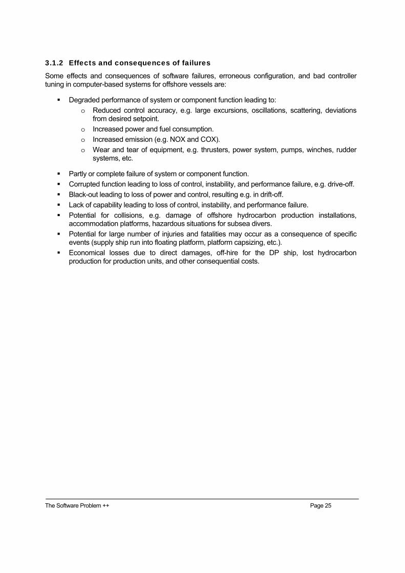
3.1.2 Effects and consequences of failures
Some effects and consequences of software failures, erroneous configuration, and bad controller tuning in computer-based systems for offshore vessels are:
Degraded performance of system or component function leading to: o Reduced control accuracy, e.g. large excursions, oscillations, scattering, deviations
from desired setpoint. o Increased power and fuel consumption. o Increased emission (e.g. NOX and COX). o Wear and tear of equipment, e.g. thrusters, power system, pumps, winches, rudder
systems, etc.
Partly or complete failure of system or component function. Corrupted function leading to loss of control, instability, and performance failure, e.g. drive-off. Black-out leading to loss of power and control, resulting e.g. in drift-off. Lack of capability leading to loss of control, instability, and performance failure. Potential for collisions, e.g. damage of offshore hydrocarbon production installations,
accommodation platforms, hazardous situations for subsea divers. Potential for large number of injuries and fatalities may occur as a consequence of specific
events (supply ship run into floating platform, platform capsizing, etc.). Economical losses due to direct damages, off-hire for the DP ship, lost hydrocarbon
production for production units, and other consequential costs.
The Software Problem ++ Page 26
3.2 Drivers for technology progress In the last 10-20 years a technology shift has taken place by the introduction of computer-based systems in marine vessels. As enabling technologies such as electronics, communication, and SW have provided more cost-effective solutions in order to give more advanced functionality and autonomy, the technology level has dramatically increased. Some of the main drivers and related trends for this development are:
Profit: o Demand for increased availability (e.g. extended weather windows, higher accuracy,
and possibility to do more advanced operations). o Reduced manning. o Requirements for reduced damage to materials, equipment, and property. o Focus on cost leads to cheaper technological solutions. o Improved tools and technology reduces R&D cost. (This will probably increase the
number of vendors entering the market as their initial cost is reduced.)
Safety: o New technology enables new safety features. o Higher ethical responsibility with respect to injury or loss of life. o Increased focus on environmental issues. o Increased public awareness and media focus.
Technology: o New technological possibilities create new demands in the market. o Low-cost technologies enable new solutions. o Low-cost off-the shelf HW/SW technologies open up for new vendors.
One should notice that some of the requirements and drivers are contradictory to each other; e.g. extreme focus on installation cost (CAPEX) as opposed to operational cost (OPEX), availability, and safety. One of the main goals must be to achieve the desired technology progress without violating the necessary quality and safety level by unwanted SW problems.
3.3 Practice for quality assurance in maritime industry The ideal manufacturing and installation process of computer-based systems in ships are indicated in Figure 6.
However, the ideal process as indicated, with a parallel HW and SW production phase and a subsequent test phase before system delivery is not achieved in practice. In real-life the SW production is usually delayed in the project, with the result that SW code is often implemented and configured in haste and thus leading to a large number of software bugs and configuration errors. The subsequent test activity then often becomes more extensive and proceeds until the ship MUST leave the yard and often continues into the operational phase of the ship. Please refer to Figure 7 for this real-life production process.
The Software Problem ++ Page 27
Figure 6: Ideal production of control system (DNV)
Figure 7: Real life production of control system (DNV)
Contract
HW design
HW production
Software production
Test
Delivery
Installation
Ship leaving yard
Contract
HW design
HW production
Software production
Testing
Delivery
Installation/Commissioning
Ship leaving yard
The Software Problem ++ Page 28
A consequence of the resulting real-life implementation of the project is that software bugs and functional deficiencies are not discovered before the ship is in full operation.
Some software failures may be identified after an initial event leading to an incident/accident or as a loss of a safety function during an emergency. Please refer to Figure 8.
System tests (FAT)
Tests on board
Revealed during normal operation
Software problems identification
Identified during accidentsand emergency handling, ornever identified
Figure 8: Identification of Software Problems during the life cycle of the ship
The Software Problem ++ Page 29
3.3.1 Quality assurance, verification, validation
When evaluating Quality Assurance (QA) practice and testing, it is distinguished between verification activities and validation activities:
Verification: To test that a component, subsystem, or the entire control system satisfies its functional description and requirement specification.
Validation: To test that a component or system satisfies its purpose, philosophy, and the user/customer demands, as well as ensuring the safety of personnel, equipment, and environment. The acceptance criteria are set by the system philosophy, classification rules, laws and regulations, common sense, and good practice.
While verification purely tests the system with respect to the documented requirement specification, validation will additionally question the correctness and feasibility of the requirement specification with respect to philosophy, rules and regulations, societal norms, and so forth.
The lifecycle of marine computer-based systems is mainly divided into two phases:
1. The new-building phase, and
2. The operational (or sailing) phase.
3.3.2 Quality assurance during the new-building phase
In present industry practice, some existing verification activities of computer-based systems in the new-building phase, depending on application, are:
Design review: The system requirements (adequate actuator forces and power demand, sensor architecture, communication and network, operator station design, etc.) are reviewed with respect to customer specifications, applicable rules and regulations, capability analysis, etc. Design review is a process at several levels in the project and between several involved participants, e.g. review of system requirements as an interaction between yard and vendor. Please also refer to Figure 9.
Failure Modes and Effects Analyses (FMEA): Determine the response of a system to defined single failures. This is to ensure that adequate redundancy is implemented in order to assure robustness and availability of the system with respect to these single failures. A Failure Mode and Effect Analysis is strictly defined as a systematic process for identifying potential design and process failures before they occur, with the intent to eliminate them or minimize the risk associated with them [16]. The FMEA is largely conducted as a desktop study. Additionally, an FMEA test program is usually conducted at sea trials to test the as-built installation, in order to verify different failure modes and that sufficient redundancy is implemented. Today the FMEA is an integral part of the test program for the manufacturing and operation of many safety-critical maritime systems.
Factory Acceptance Test (FAT): Normally open-loop tests at vendor factory (can also be a pure HW test and/or limited closed-loop function test using a simulator) aimed at verifying
The Software Problem ++ Page 30
conformance to the software system functional description. The FAT is approved by the yard and ship owner, and may be witnessed by class society. If applicable, the CMC certificate from the classification society is issued after the FAT. This certificate is based on the rules for ship classification and the approved test program(s). Please also refer to Figure 9.
Mechanical completion: Verify completeness of the installation according to the engineering manufacturing plan. Mechanical completion and commissioning verify correct function of the intact integrated system. The FMEA, on the other hand, focuses on revealing the effects of failures in the system; in particular, the effect of the worst-case failure(s).
Commissioning test (in dock/at quay/at sea): Assure completeness and correct functioning of components, subsystems, system loops, and interfaces. Normally open-loop testing aimed at verifying the integrated system’s architecture and installation in the vessel. Approved by yard, ship owner, and witnessed by class society, if applicable.
The final validation before the ship leaves the yard is an FMEA test program and functional testing conducted at:
1. Sea trial, often called Customer Acceptance Test (CAT): Open-loop tests in dock trials and closed-loop tests at sea trials aimed at verifying conformance to the software system functional description and validating the overall system installation for the safety requirements specification. Approved by yard and ship owner, and witnessed by class society. The full-scale test program (CAT and FMEA redundancy testing) has the following characteristics in today’s practice:
Usually the ONLY closed-loop functional test activity for verification of the overall control system performance (the IMCA guidance document on FMEAs [16] describes this test activity as integral in the FMEA test program to verify the overall system’s response to failures).
Usually the FIRST and ONLY overall functional test of the application software before hand-over to the customer.
Only a minor part of the software problems (bugs, design weaknesses, functional deficiencies, lack of specifications) are assumed revealed.
Only a limited part of the system functions and a limited amount of failure modes (to verify proper failure handling) are possible to test at sea trials.
Tests usually occur in calm environmental conditions. Hence, performance testing subject to varying environmental conditions is delayed until vessel operation.
Often the full-scale test program at the sea trial is performed by the yard’s and supplier’s engineers and not the crew which shall take over and operate the systems.
There is strict and concentrated adherence of the sea trial system operators to the operational procedures.
After successful sea trials the classification society issues a class certificate with corresponding notations for the vessel.
The Software Problem ++ Page 31
Figure 9: Some available methods for qualification of a SW-based system (DNV)
3.3.3 Quality Assurance during the operational phase
The operational phase of a ship starts when the ship owner has accepted the ship from the yard. From a quality assurance point of view, the following observations are made:
1. The operational phase can in some sense be viewed as a continuous functional test of the control systems by trial and error. Compared to the formal full-scale test program in the new-building phase, it then has the more practical characteristics:
Real duration test of the application software. Many software problems (bugs, design weaknesses, functional deficiencies, lack of
specifications) are first revealed in this phase. The closed-loop system exposed to all feasible environmental conditions. The closed-loop system exposed to real-life equipment failures. Real-life adherence of the sailing operators to the operational procedures. For instance,
[8] estimates that 80% of time the operators are performing routine tasks of monitoring and checking the system (boredom), 15% of time they are performing non-automated operational tasks, and finally about 5% of time they may encounter irregular or emergency situations.
Ad-hoc reconfiguration of the computer-based system (alarm settings, disabling of important features, etc.).
Ad-hoc patching of software (application software, system software).
2. The effects and consequences of revealing failures during operation may give huge consequences with respect to the safety of human, equipment, and the environment. Failures resulting in off-hire are very expensive. Traveling cost and time for maintenance personnel may also be very high.
Control and monitoring
system
SW Code verification
QA SW
Design Approval
FMEA
TestingOthers
The Software Problem ++ Page 32
3. In the operational phase, one must in addition always be aware of the Human Factor. The critical systems will often require skilled operators for normal operation. The normal operation of well functioning systems will often be handled in a satisfactorily manner by most crews. However, when failures or operational incidents occur, the operators will need special emergency procedures and training for possible emergency situations. The emergency handling of the vessel and the systems will often require completely different procedures than for normal handling.
In the operational phase the quality assurance activities are mainly related to the following events:
Periodic HW/SW upgrades: Equipment maintenance, upgrades, and extensions. Owners periodical maintenance and functional testing Periodical class survey: Depending on application, periodical surveys according to
classification rules are carried out by class society (for DP every 2.5 years by DNV rules). The scope is often reduced compared to the new-building scope for certification, depending on the degree of maintenance and retrofit of the system.
Retrofit and possibly recertification: Modifications to the systems may require recertification and issuance of a new certificate.
In practice, ship operators and contractors experience that many incidents are related to SW reconfiguration and upgrades in the operational phase. It therefore seems that there is a need for improved quality assurance related to reconfiguration and SW version handling.
The Software Problem ++ Page 33
3.4 Observations and problems related to computer-based control and monitoring systems
The following items are generally observed:
Lack of sufficient documentation of the overall and detailed risks related to operation of the ship and the systems.
Lack of overall and detailed functional requirements specifications of systems onboard. The risk/criticality elements of the various systems in a given ship and given operations are not visible to owner/operator, yard, supplier, and the classification society.
The maritime industry has traditionally considered remote control and monitoring systems to be not very critical. The reason for this is a general operational assumption that such systems shall be possible to be handled by available and competent crew to carry out manual backup routines, local control, or similar. Under these assumptions this means that SW/HW inside such systems should not be considered as very critical and the systems should not be subject to extensive quality assurance. (In this understanding there is no software problem, and there is only an operational responsibility for the operator to organize sufficient manual backup as a fallback.)
Lack of understanding in the marine industry that above general low criticality assumption are not valid for all ships/operations/systems anymore. In some operational modes, systems cannot be handled safely by manual procedures, especially if unexpected events or failures occur. The problem is therefore to acknowledge that such systems will require complete automatic response within very limited response times. Such systems should be subject to extensive quality assurance during the complete lifecycle of the system. Identification of such operations/systems should become more visible in industrial requirements and rules/regulations, and maritime industry should implement extensive quality assurance of such systems. It may be a problem to convince the industry that costs related to more extensive testing and verification are necessary.
Systems onboard vessels have become more complex, driven by economy, environmental requirements, comfort, operational, and maintenance desires. More failures may occur to complex systems and the failure effects are more difficult to predict. Emergency procedures and training for handling failed complex systems and equipment are often not sufficient for safe operation of the systems.
Reduced manning with less general training, including training for emergency handling of complex systems.
The Software Problem ++ Page 34
3.4.1 Types of problems
The main SW problems are summarized in Table 1.
Table 1: Types of software problems Problem category: Description:
Design weaknesses
These often come as a result of in-house commitment to design history, lack of system understanding, and/or use of low-cost technology. Some typical aspects are:
Lack of documented hazard identification and risk assessment as basis for the detailed design
Poor or very high level functional specifications of the systems Badly designed human-machine interface. Insufficient capability. Lack of stability margins for the closed-loop system. Flaws in system design philosophy.
Lack of interface specifications between systems
Software bugs
These are the traditional software errors that for some reason have escaped the software functional testing. Software coding generally results in many such bugs, and they are usually patched by new software updates and upgrades. The real challenge is to write high quality code and to discover bugs early enough to avoid extensive patching.
Another possible software problem is that often the control application is developed as a stand-alone system but integrated in the final installation in a larger system. Even if such a system functions perfectly by itself, it may not be robust in the integrated system – e.g. with respect to communication network storms, sharing of resources, protocols, connectivity, flags, etc.
Configuration errors
These concern application specific configuration parameters defined for each project installation. Some of these are set by the vendor technician in the new-building phase and hidden to the operator, while other parameters are open for reconfiguration by the operator in operation. Typical parameters are:
Alarm and warning threshold settings (often available to operator). Controller tuning parameters (defined by vendor and limited availability to operator). Sensor settings, e.g. offsets (defined by vendor and partly available to operator). Signal processing parameters, e.g. filter gains, threshold margins, etc. (defined by
vendor and partly available to operator)
A typical problem is that parameters are changed during operation. The drill ship incident (Case 1) described in Section 2.2 is an example of such an error.
The Software Problem ++ Page 35
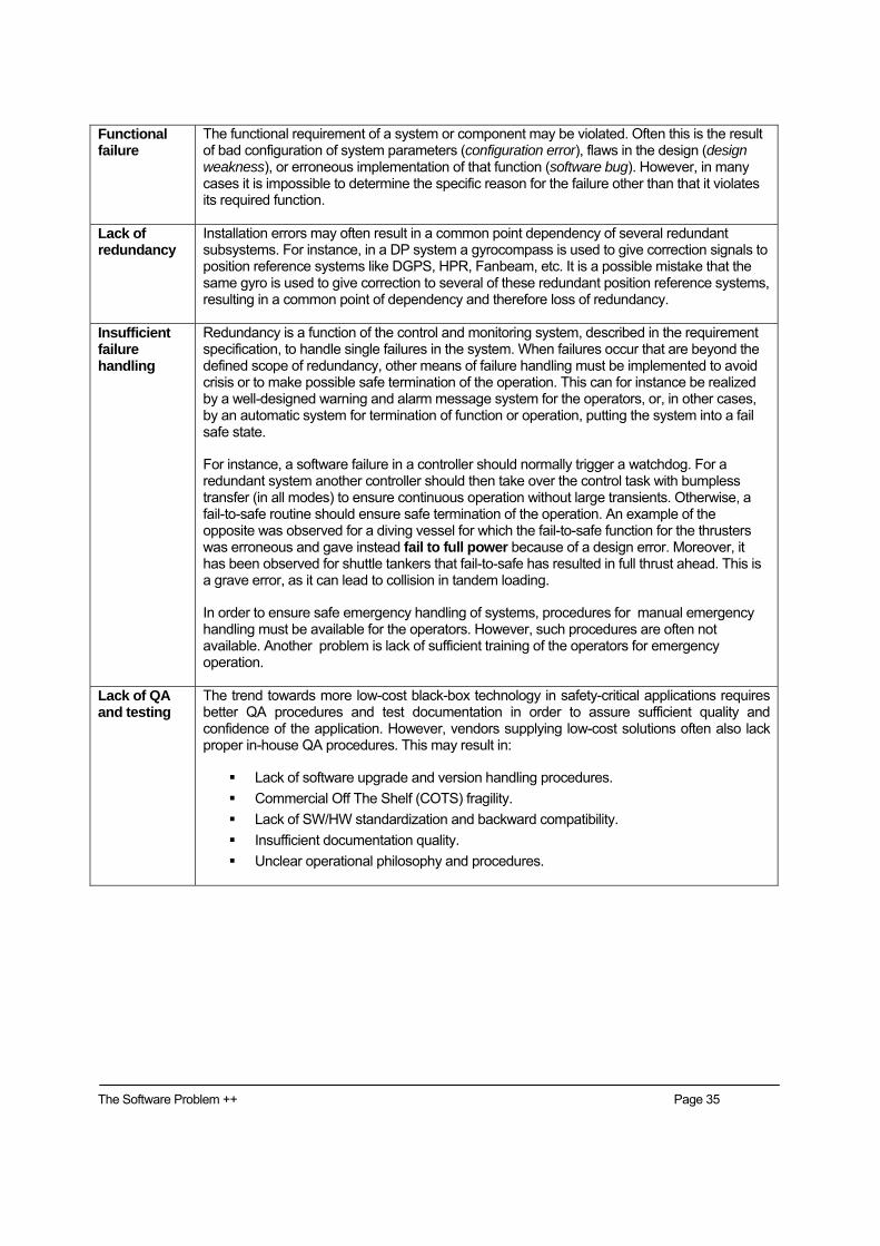
Functional failure
The functional requirement of a system or component may be violated. Often this is the result of bad configuration of system parameters (configuration error), flaws in the design (design weakness), or erroneous implementation of that function (software bug). However, in many cases it is impossible to determine the specific reason for the failure other than that it violates its required function.
Lack of redundancy
Installation errors may often result in a common point dependency of several redundant subsystems. For instance, in a DP system a gyrocompass is used to give correction signals to position reference systems like DGPS, HPR, Fanbeam, etc. It is a possible mistake that the same gyro is used to give correction to several of these redundant position reference systems, resulting in a common point of dependency and therefore loss of redundancy.
Insufficient failure handling
Redundancy is a function of the control and monitoring system, described in the requirement specification, to handle single failures in the system. When failures occur that are beyond the defined scope of redundancy, other means of failure handling must be implemented to avoid crisis or to make possible safe termination of the operation. This can for instance be realized by a well-designed warning and alarm message system for the operators, or, in other cases, by an automatic system for termination of function or operation, putting the system into a fail safe state.
For instance, a software failure in a controller should normally trigger a watchdog. For a redundant system another controller should then take over the control task with bumpless transfer (in all modes) to ensure continuous operation without large transients. Otherwise, a fail-to-safe routine should ensure safe termination of the operation. An example of the opposite was observed for a diving vessel for which the fail-to-safe function for the thrusters was erroneous and gave instead fail to full power because of a design error. Moreover, it has been observed for shuttle tankers that fail-to-safe has resulted in full thrust ahead. This is a grave error, as it can lead to collision in tandem loading.
In order to ensure safe emergency handling of systems, procedures for manual emergency handling must be available for the operators. However, such procedures are often not available. Another problem is lack of sufficient training of the operators for emergency operation.
Lack of QA and testing
The trend towards more low-cost black-box technology in safety-critical applications requires better QA procedures and test documentation in order to assure sufficient quality and confidence of the application. However, vendors supplying low-cost solutions often also lack proper in-house QA procedures. This may result in:
Lack of software upgrade and version handling procedures. Commercial Off The Shelf (COTS) fragility. Lack of SW/HW standardization and backward compatibility. Insufficient documentation quality. Unclear operational philosophy and procedures.
The Software Problem ++ Page 36
Conclusion During recent years have many problems related to computer-based systems in offshore vessels been termed “software problems.” This report has shown, however, that the problems experienced are also related to design, fabrication, operation, and maintenance of the systems. This report has therefore denoted these as ‘Software Problems ++.’
Below is a summary of the main types of ‘software problems ++’ identified for shipboard control and monitoring systems:
1. Formal identification of hazards and operational risks during the design phase is often not carried out to the necessary extent. Operational risks for some marine operations have increased without a formal identification process of the risks.
2. Design weaknesses including low-quality specifications of functional requirements.
3. In the maritime industry, remote control systems have traditionally been considered as not very critical due to the requirement of having manual backup solutions and competent crew available. These assumptions are often not valid for new complex designs which may actually require fast automatic response to failures. Due to the traditional notion that failures of such control systems are not very critical, the industry has not increased the quality assurance in the same pace as the criticality and complexity of modern solutions have increased.
4. Owners/operators prefer to solutions with lowest investment costs although this may give large increases in operational costs. This price pressure does not motivate suppliers to increase quality assurance before delivery of such systems.
5. Interaction problems between hardware, software, and the human operator, e.g. improper design of the human-machine interfaces.
6. Use of Commercial-Off-The-Shelf (COTS) software and hardware into critical applications.
7. Quality assurance problems related to purchase of software, production of software, version control, testing at manufacturer.
8. Lack of a nominated contractor responsible for integration of subsystems from several sub-suppliers, resulting in subsystem interface problems.
9. Completion of systems carried out after delivery and during operational phase. Updates of software code and configuration data not properly justified, tested, and documented.
10. Sea trial testing often limited to normal operational modes and the quantity of testing may be at a minimum.
11. Reduced manning and crews with low competence on complex software based systems.
12. Procedures and operator training for emergency operation of failed systems have not been sufficient for successful emergency handling.
The Software Problem ++ Page 37
13. Procedures and tools for verification and testing of complex control and monitoring systems for ships and offshore vessels have not been developed with the same speed as the development of complex products and integrated systems.
This report has emphasized the increasing importance of software in the safety of the overall ship/vessel systems. The report should next be used as basis for proposing adequate measures for dealing with the identified software problems. In this context one should consider a lifecycle framework according to e.g. the IEC 61508 [9] and look into new methods for testing, verification, and validation. Some relevant methods/procedures are:
hardware-in-the-loop (HIL) simulations for revealing errors and weaknesses, and
appropriate procedures for software upgrade and version handling for minimizing problems related to maintenance and retrofit.
However, an evaluation of existing methods should also be performed in order to fit these into an overall framework for quality assurance, verification, and validation of safety-critical control and monitoring systems for offshore vessels.