The Teallach Tool: Using Models for Flexible User Interface Design Peter J. Barclay 2 , Tony Griffiths 1 , Jo McKirdy 3 , Norman W. Paton 1 , Richard Cooper 3 , Jessie Kennedy 2 1 Department of Computer Science, University of Manchester, Oxford Road, Manchester M13 9PL, UK. Email: { griffitt, norm } @cs.man.ac.uk 2 Department of Computing Studies, Napier University, Canal Court, 42 Craiglockhart Avenue, Edinburgh EH14 1LT, UK. Email: { pjb, jessie} @dcs.napier.ac.uk 3 Department of Computing Science, University of Glasgow, Glasgow G12 8QQ, UK. Email: { jo, rich} @dcs.gla.ac.uk http://www.dcs.gla.ac.uk/research/teallach/ Abstract Model-based user interface development environments aim to provide designers with a more systematic approach to user interface development using a particular design method. This method is realised through tools which support the construction and linkage of the supported models. This paper presents the tools which support the construction of the Teallach models in the context of the Teallach design method. Distinctive features of the Teallach tool include comprehensive facilities for relating the different models, and the provision of a flexible design method in which models can be constructed and related by designers in different orders and in different ways. 1. INTRODUCTION The development and maintenance of user interface software is challenging. Although interface development environments provide facilities that allow individual components within an interface to be constructed without recourse to programming, the behaviour of user interfaces is
Transcript
The Teallach Tool:Using Models for Flexible User Interface Design
Peter J. Barclay2, Tony Griffiths1, Jo McKirdy3, Norman W. Paton1, RichardCooper3, Jessie Kennedy2
1Department of Computer Science, University of Manchester,Oxford Road, Manchester M13 9PL, UK.Email: { griffitt, norm } @cs.man.ac.uk
3Department of Computing Science, University of Glasgow,Glasgow G12 8QQ, UK.Email: { jo, rich} @dcs.gla.ac.uk
http://www.dcs.gla.ac.uk/research/teallach/
Abstract Model-based user interface development environments aim to providedesigners with a more systematic approach to user interface developmentusing a particular design method. This method is realised through tools whichsupport the construction and linkage of the supported models. This paperpresents the tools which support the construction of the Teallach models in thecontext of the Teallach design method. Distinctive features of the Teallachtool include comprehensive facilities for relating the different models, and theprovision of a flexible design method in which models can be constructed andrelated by designers in different orders and in different ways.
1. INTRODUCTION
The development and maintenance of user interface software ischallenging. Although interface development environments provide facilitiesthat allow individual components within an interface to be constructedwithout recourse to programming, the behaviour of user interfaces is
The Teallach Tool
generally implemented by complex, hand crafted software systems.Although design patterns can be used to provide an organisationalframework for interface software, it is still the case that user interfacesoftware is intrinsically complex, and that changing an existing interface toreflect changing requirements and to take account of user feedback is alaborious and often somewhat ad-hoc process.
Model-based user interface development environments (MB-UIDEs)have been developed with a view to providing a more systematic approach touser interface development, building in particular on abstract models ofdifferent aspects of user interface functionality (e.g., TADEUS [11], FUSE[7] and MOBI-D [10]). Typically, a MB-UIDE will include domain, task,dialogue and presentation models. The benefits that it is hoped will arisefrom the use of MB-UIDEs include the generation of interface softwarebased on the abstract models, and more seamless integration of the interfacedesign and implementation processes.
However, although MB-UIDEs have a range of promising characteristicsfor easing user interface development, they introduce a number of newchallenges. The development of effective tools for the construction andlinking of a collection of abstract models is itself a substantial challenge,which must be addressed in the context of a design method that directs theinterface developer in the construction of a coherent collection of models.This paper seeks to address these two issues – tools for model constructionand tool support for a design method – in the context of the Teallach MB-UIDE [6]. Distinctive features of the Teallach tool include comprehensivefacilities for relating the different models, and the provision of a flexibledesign method in which models can be constructed and related by designersin different orders and in different ways.
The paper is structured as follows. Section 2 sets the scene byintroducing the Teallach system. Section 3 describes a case study that will beused throughout the paper. Section 4 outlines the flexible design methodsupported by Teallach, and which must be accounted for in the tool. Section5 describes the facilities provided by the tool for editing and relating theTeallach models. Section 6 presents some conclusions.
2. TEALLACH BACKGROUND AND MOTIVATION
The Teallach MB-UIDE is primarily concerned with constructing user-interfaces to object oriented databases. The Teallach user is the designer ofinterfaces to database applications, not the end-user of these interfaces. Inorder to meet the needs of such design efforts, Teallach provides three
Barclay, Griffiths, McKirdy, Paton, Cooper & Kennedy
models: a domain model, a task model, and a presentation model. Thesemodels are described in detail in [6].
The presence of underlying models gives some advantages to aninterface-building tool, such as a clear semantics for the interface underconstruction, and facilities for the automatic checking of consistency in themodels (and hence in the resulting interfaces), together with support for‘help’ and ‘undo’ functionality. However, we have identified a number ofweaknesses in existing MB-UIDEs. Some of these are described below; formore details, the reader is referred to [4].• Some systems impose a rigid methodology on the interface-designer.• Most systems do not provide the facilities to work with database-specific
concepts, such as transactions.• Many systems have a fixed set of widgets from which interfaces can be
constructed, thereby disallowing the use of application specific widgetswhich may be required in some domains.
• Few systems have a clear method for representing flow of stateinformation within the interface to be generated.
One of the goals of the Teallach project is to develop models that addresssome of these shortfalls, and to build a prototype tool that illustrates oursolutions. In particular, we do not wish to impose a particular style ofworking on the interface designer. For example, one designer may wish toproceed from specifications to implementations, whereas another may wishfirst to sketch forms to be used in the interface, and then connect these toapplication functionality. Both these approaches, and others, are allowed byTeallach. This is achieved by 1) treating all of the models in an even-handedmanner, and 2) performing consistency checking as late as possible, so thatthe designer is free to work through ‘inconsistent’ designs towards consistentones. In particular, automatic generation of model components may be usedas the designer desires: it is possible to generate large parts of the interfaceautomatically (and optionally modify these generated components), or to‘wire together’ user-built substructures with no use of automatic generation.
Teallach’s interfaces are realised as compiled Java applications, givingthe efficiency of compiled code while running on any major platform. Thewidgets used are taken from Java’s Swing widget set [2], but additional user-supplied widgets may be added to the toolkit and used at any time. Access todatabase-specific concepts is supplied through Teallach’s ODMG-style [1]domain model.
The Teallach Tool
3. CASE STUDY
To provide a tangible explanation of the manner in which the Teallachtools operate and are used, subsequent tool discussion will be conducted inrelation to a case study, which is a library database application – the UMLclass diagram of this is shown in figure 1.
For brevity, consider a single task that the user of a library applicationmight perform – that is searching for a book. Using the application, the userindicates that a search is to be performed, and subsequently specifies acollection of search parameters which constitute the attributes on which thesearch is to be based – for example, a search based on a named author. Theuser then initiates the search (amounting to the running of a queryparameterised by the specified information) and is presented with theresultant information. Assuming one or more books were returned, the usercan browse through them. The remainder of this paper demonstrates, interms of one possible traversal of the Teallach method using the tools, how adesigner might construct a user interface to support this task.
4. THE TEALLACH METHOD
One of the principle aims of Teallach is the provision of a flexible designmethod such that designers using Teallach are not restricted to a singledevelopmental strategy. Although some might question this approach giventhe more rigid methods promoted by other MB-UIDEs [4], themethodological stance adopted by Teallach arose from the followingobservations. Firstly, there is little evidence to support the notion that the
Figure 1: The Library Database Schema
Librarian
Person
ProhibitedBookException
Student
1
on loan to
loans
*
*
books
in
1
name : Stringpassword: Stringsalary: intloans: Book[]
String getName()void setName()
Book
title : Stringauthor: Stringyear: StringonLoanTo : PersonownedBy: Library
name : Stringpassword: StringmatricNo: intloans: Book[]
String getName()void setName()
Barclay, Griffiths, McKirdy, Paton, Cooper & Kennedy
less flexible methods forwarded by other MB-UIDEs are indeed the best (oronly) approaches; forcing designers along a linear developmental pathappears overly restrictive and does not support the characteristics of thesoftware development life cycles that designers often favour. For example,one could indicate that TADEUS [11] operates by successively refining atask model through a dialogue model and a number of interaction tables.Secondly, Teallach recognises that if it is to be adopted as a means of userinterface development, then it needs to observe the developmental habits ofsoftware developers who often work in iterative cycles of developmentwhere various aspects of their artefacts are developed in parallel or in aninterleaved manner [8]. Through its flexible methodology, Teallach aims tosupport (as far as possible) the observed working practice of softwaredevelopers.
Figure 2 shows the flexible methodological structure proposed byTeallach and which is subsequently realised in the Teallach tools. Due to thenumber of potential routes through the method – made possible by itsinherent flexibility – it is not feasible to discuss each. Instead, theinteractivity and dependencies between the steps in the method will bediscussed at a high level, with the intention that the discussion provides afeel for the developmental freedom available to the designer. Later
Figure 2: The Teallach Method
DOMAIN
MODEL
PRESENTATION
MODEL
Abstract
Concrete
TASK
MODEL
generation of domain modelpersistent components
continuing iterative inclusion of auxiliary data types
continuing iterative generation of database access-related components
1
**
*
*
*
*
*
Verification ofModels
GENERATED
USER
INTERFACE
*registration ofgenerated userinterface as widgetin presentationmodel
continuing iterative independent development of task model components
continuing iterative generationof presentation modelcomponents from domainmodel components
continuing iterative generationof task model components from
domain model components
continuing iterative generation of
presentation model components from task model components & vice versa
START
* * independent generation ofpresentation model components
independent development oftask model components
*
continuing iterativeindependent generation ®istration of presentationmodel components
BCD E
F
G
c
b
a
Key: * repeatable action
1 action performed once only
user action
system action
a
A
Code Generation
The Teallach Tool
discussion of the actual Teallach tools, by which the method is realised, willdemonstrate one possible path through the method.
Teallach refers to a design effort as a project – that is, a collection ofmodels which contribute to the development of a specific user interface.Projects can be saved during the course of development, and components ofone project can be imported into another to facilitate reuse. The remainder ofthis discussion will assume that the developer is creating a new project. Itshould be noted that the aim of this section is to outline the Teallach method– the means by which the actions may be performed using the tools isdiscussed in section 5.
Teallach has been developed to facilitate the design of user interfaces topre-existing object oriented databases (OODBs). There is therefore a basicassumption that the schema and classes for the underlying database mustexist prior to user interface development. The Teallach tool therefore permitsone entry point to the developmental cycle (as shown in Figure 2). Thisallows the structure of the underlying database application to be establishedwithin a project in the form of the persistent components of a project-specific domain model (step A). Having determined the persistencecapability of the application, the developer is then free to design each of theindividual Teallach models.
At any stage in the design of a user interface, each of the models can beindependently developed. Consider first the domain model. As required, thedeveloper can create components to facilitate access to the underlyingdatabase (database connectivity components) and can import informationabout auxiliary data types which may be required for the runtime operationof the application – see the steps labelled (a) in figure 2. It should be notedthat the domain model also provides the facility to view and utilise the typesprovided by the Java API – a subset of the auxiliary information available toTeallach. The inclusion of these components is a one-off action which can beperformed at any stage during development.
Consider now the task model. Independently of the other Teallachmodels, components (and hierarchies of components) within the task modelcan be created, manipulated, and deleted – as shown by steps (C) and (c) infigure 2. Similarly, the developer can, independently of the domain and taskmodels, create, manipulate and delete components (and hierarchies ofcomponents) within the presentation model and can register new widgets(steps (B) and (b) in figure 2). Each of these activities can be performed atany stage during user interface development.
At any point during development the designer can either associatecomponents from distinct models (thus linking the models to generate acohesive user interface design) or can generate new components in a modelfrom a component previously constructed in another model. Such activities
Barclay, Griffiths, McKirdy, Paton, Cooper & Kennedy
are represented by steps (D), (E) and (F) in figure 2 (and also labelled in theactual tool shown in figure 3). These activities can be performed repeatedlyand in any order.
Consider first step (D), which shows the association of task modelcomponents with domain model components. The designer can use a domainmodel structure to automatically generate an initial task hierarchy, or canlink components in the two models through the use of state objects. A stateobject is the means by which the task model represents constructs importedfrom the other Teallach models. Greater detail of these associations is givenin section 5. Step (E) supports a similar scenario where the domain modelcomponents are used to automatically generate a presentation. Further detailsof these associations are also given in Section 5.
In Teallach, the task model is not tied to a specific visual representationof a user interface. This maxim is realised in the tool by linking task modelcomponents to high-level abstractions of concrete presentation modelconstructs (termed the abstract presentation model). In step (F) componentsin the abstract presentation and task models can be linked together, or can beused to automatically generate a new component in the other model. In allsuch operations, the designer will create a state object in the task model torepresent the linked presentation model component.
F
Figure 3: The Teallach Tool and Possible Inter-model Operations.
D
E
The Teallach Tool
At any stage during design, the developer can choose to verify thevarious models; a step which determines the consistency and completenessof the models with respect to one another. Assuming model verification hassucceeded, the designer can automatically generate a user interface asdescribed by the models. The developer can either choose to accept thegenerated interface, or can return to the various models and continue thedesign process in an iterative cycle. The designer can choose to register anygenerated user interface as a self-contained "black-box" widget within thepresentation model (see step (G)), thus facilitating a bootstrapping process ofdevelopment and reuse of generated components.
From the above discussion it can be seen that, with the exception of step(A), provided that the required components exist within each model, any ofthe discussed steps can be performed in any order and any number of times.Hence designers are given the freedom to work in the manner most suited tothemselves and their projects, and are not restricted by an overly prescriptivedevelopmental strategy.
5. THE TEALLACH TOOL
5.1 General
The Teallach tool has been implemented using Java 2.0 and the SwingGUI tool-set. This tool-set has provided us with a rich library of GUIprimitives that facilitate design using the model-view-controller pattern; ourexperiences with both this tool-set and Java in general have been mainlyfavourable. It has been designed so that Teallach itself, and the interfaces itgenerates which are also implemented in Java, will run on all majorhardware and OS platforms. Teallach interacts with the underlyingapplication (typically an OODB) through its domain model, which providesan interpretation of the contents of the application through the concepts ofODMG. In the current prototype Teallach has been designed to interact withthe Poet OODBMS [9].
As shown in figure 3, the tool provides separate editors for each of thethree models, implemented using a desktop metaphor. In addition, thepresentation model provides further, free-floating windows, such as apreview of the interface under construction, and a palette of widgets thedesigner can use. Model constructs can be exchanged between the editorseither by drag-and-drop or by cut-and-paste metaphors using a single systemclipboard.
The semantics of inter-model associations are described in more detailbelow, but the basic scheme is as follows: when a fragment of one model is
Barclay, Griffiths, McKirdy, Paton, Cooper & Kennedy
dropped into the editor of a different model, some new structure is generatedin the target editor, derived from the source model (drag-and-generate). It isalso possible to ‘link’ components from different models, for example toshow that a particular widget is to be used to perform a particular task. Thisis achieved by switching the tool into link mode and drawing arcs betweenthe associated components (click-and-link). The large arrows in figure 3show the possible ways in which the three Teallach models can interact.
5.2 The Domain Model Editor
A project-specific Teallach domain model reflects the structure andfunctionality of the underlying application, database connectivity, andauxiliary data types such that they can inform and link into the userinterface. To provide a measure of platform independence, the domainmodel represents these factors using constructs derived from the conceptsspecified in the ODMG object database standard.
The domain model editor within the Teallach tool comprises fourindependent panels, representing: persistent data components, importedauxiliary classes, auxiliary classes derived from the Java API, and thedatabase connectivity aspects of an application. A domain model servespurely as an information source (as shown in figure 2), and as such thedomain model tool is not concerned with receipt of information from theother models. Instead, its role is to make available information to the othermodels in a uniform manner such that the persistence of the data istransparent.
Upon start up of the Teallach development environment, as mentioned inSection 4, a model of the persistent data related components of theapplication is generated. This is done automatically through an analysis ofthe schema of the underlying database. The domain model editor shown infigure 3 shows the persistent data components of the domain model thatrepresent the schema described in the case study.
There are also two panels concerned with the representation of auxiliarydata types, that is, data structures which are not database classes, but whichprovide functionality required for the runtime operation of the application.The first of the two auxiliary data panels provides the designer with themeans to import, as required, any user-defined classes or packages thatprovide additional functionality. To import a package or class, the designermust simply specify its fully qualified name. The screen shot in figure 4shows an auxiliary class that has been imported for use in the case study. Itprovides the facility for authentication of a string as a valid year. Once again,the designer is able to copy or drag this domain model component and pasteor drop it into one of the other models so that its functionality can be
The Teallach Tool
exploited. The second of these panels represents the data types in the JavaAPI.
The final panel within the domain model editor concerns theestablishment of components to support database connectivity. Once again,such components are modelled in terms of the appropriate ODMG concepts.Within this panel, the developer can instantiate database connections andtherein transactions. Similarly, the developer can create OQL queries thatcan be run over the underlying database. Once established, the developer cantreat database connectivity components in the same manner as other domainmodel components. Figure 5 shows the representation of a databaseconnection and transaction required for the search for book case study.Having established the connectivity with the database, the developer wouldthen be required to build the query using this same panel in the domainmodel editor.
5.3 The Presentation Model Editor
Teallach provides both a concrete presentation model (CPM) and anabstract presentation model (APM). The CPM contains real widgets such asthose available in Swing, and user-supplied custom widgets. For example,the widget JPasswordField (for capturing users’ passwords) is available fromSwing, whereas the widget TextGrabber (for inputting text) is a user-supplied widget. Arbitrarily complex Interactors, such as 3D molecule-viewers, may be used as concrete widgets provided they have beenregistered with the presentation model tool.
Figure 5: Database Connectivity PaneFigure 4: Importing Auxiliary Information
Barclay, Griffiths, McKirdy, Paton, Cooper & Kennedy
Teallach’s APM extends the light-weight presentation model described in[3]. This model defines abstract categories of widgets, designed to offer aparticular functionality. An abstract category may be realised by manydifferent concrete widgets. For example, the category Inputter representsanything which may capture the user’s input; both a JPasswordField and aTextGrabber may serve as realisations of Inputter.
The designer may use either concrete or abstract presentation objects, andintermix these freely. Of course, where abstract interactors are used, adecision must be made as to which possible realisation will be used in thefinal interface; a default is always available, so a valid interface is defined atall times. Details of how abstract categories are realised by concrete widgetsare recorded in a style, so that consistency of look-and-feel can be achieved,and differing interfaces can be easily generated which support the samefunctionality.
5.3.1 An Overview of the Presentation Model Tools
The interface designer interacts with Teallach’s presentation modelthrough a collection of related tools. The presentation model editor allowsthe designer to construct presentation fragments, whether by hand orautomatically; the widget palette provides access to the components whichmay be used for building interfaces; and the presentation meta-editor allowsthe designer to edit the meta-model of the presentation, as described below.
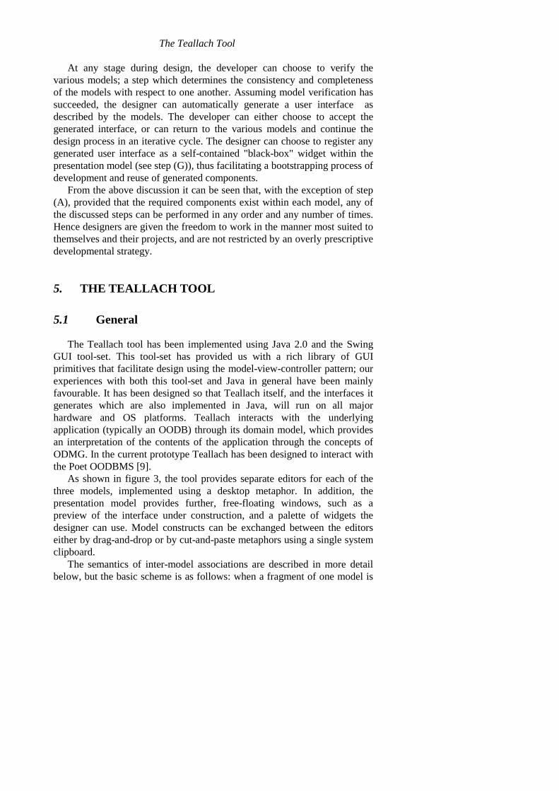
5.3.2 Constructing Interface Fragments by Hand
The designer may construct presentations by hand, by explicitlyassembling components. An example can be seen in figure 6, where thedesigner is constructing the form to be used when specifying the criteria tobe used when searching for a book. From the presentation model's widgetpalette, the designer has selected three TextGrabber components, to capturethe title, author, and year fields for the book sought. These components havebeen placed within a JPanel, which is a (usually invisible) containerprovided by Swing for grouping together related items, and ensuring thatthey behave as desired when the window is resized. An ancillary class, fromthe domain model, may be employed to ensure that the format of the textentered into the year field can represent a valid year.
The designer has then added a second JPanel to the search window,grouping two buttons that allow the user either to confirm the search criteriaand proceed to performing the search (search), or to quit from this window,if desired (quit).
The Teallach Tool
Once constructed, this interface fragment can be used in a variety ofways: 1) it can be ‘shrink-wrapped’ for later use in this and otherapplications; 2) it can be linked to constructs in the domain and task modelsto form part of the final user-interface; or 3) it can be dropped into the taskmodel to automatically generate task structures corresponding to the activityof searching for a book.
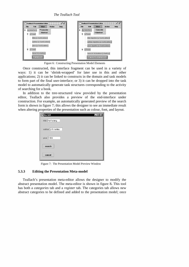
In addition to the tree-structured view provided by the presentationeditor, Teallach also provides a preview of the end-interface underconstruction. For example, an automatically generated preview of the searchform is shown in figure 7; this allows the designer to see an immediate resultwhen altering properties of the presentation such as colour, font, and layout.
5.3.3 Editing the Presentation Meta-model
Teallach’s presentation meta-editor allows the designer to modify theabstract presentation model. The meta-editor is shown in figure 8. This toolhas both a categories tab and a register tab. The categories tab allows newabstract categories to be defined and added to the presentation model; once
Figure 6: Constructing Presentation Model Elements
Figure 7: The Presentation Model Preview Window
Barclay, Griffiths, McKirdy, Paton, Cooper & Kennedy
defined, they become available for use in the abstract widget palette. Figure8 shows part of the definition of the category Inputter, derived from thecategory Item; this has a method getValue() returning an object (of any type)which has been input by the user of the widget.
The register tab allows new concrete widgets to be registered withinexisting categories. Once registered, a widget becomes available for use inthe concrete widget palette. This allows the designer to use custom-built andthird-party widgets in an interface.
The meta-editor uses the meta-data it collects to automatically write Javacode implementing the newly defined meta-objects. This code is thencompiled reflectively, so that the new objects can become available in thesystem without need for interpretation.
5.4 The Task Model Editor
The Teallach task model tool provides an environment for constructingand editing hierarchical task models, the semantics of which have beenpresented in [5]. A hierarchy constructed using the task model tool is atemporally ordered representation of the goals and subgoals a user wishes toachieve in the developed interface. The Teallach task model is novel in thatit provides a designer with the ability to declare local state and associate thiswith a task, and subsequently to indicate how this state information isinitialised and utilised within a task.
To realise the task model for the case study, our designer constructs ahigh-level specification of the task they intend application end-users toperform through the modelled interface. To achieve this, the designer drags atask of the required type from the task model’s palette of task types (shownin figure 3) and drops it at the required location in the task modelconstruction area.
Figure 8: the Presentation Model Meta-Editor
The Teallach Tool
At the lowest level in the task hierarchy, the designer creates interactionand action tasks which represent how the application processes information,and how the end-user and the application participate in the task. These tasksmay have links to domain or presentation model functionality which isrealised and invoked through a suitably initialised state object (as describedin section 5.5.1).
5.5 Establishing Model Interaction Using Link Mode
At any time during the model development process, the designer maycreate links between components specified in any of the Teallach models. Bycreating a link, the designer is stating, for example, that a widget is to beused to perform a particular task, or that an action task corresponds to aninvocation of an operation on an application class. Links between the Taskand Presentation models are also used to describe dialogue dynamics. Thissection will show how, through the use of state objects representing bothdomain and presentation model constructs, the task model tool provides thefacility to bind together the concepts in the three Teallach models.
5.5.1 Creating and Using State Information in the Tool
A state object is the means by which the task model tool maintainsreferences to constructs from the other Teallach model tools, and isconstructed through either a paste as state menu option, or as a side-effect ofTeallach automatically generating a task construct from another Teallachmodel construct. A state object refers to a named instance of either a domainor abstract presentation model class, and is realised as a uniquely namedrectangle within the scope of a non-primitive task.
Once a state object has been created it can be utilised in several ways.For example, one of the state object’s methods can be invoked (equivalent toinvoking underlying application or widget functionality), or one (or more) ofa state object’s public attributes can be read from or written to (equivalent tospecifying the flow of information between the user and the underlyingapplication).
For the purposes of our case study, the designer needs to specify that thesearch criteria provided by the end-user should be stored in a named objectof type Book, and that a named query should be invoked on the databasewith this Book object as the search parameter. The designer therefore copiesthe Book persistent domain class from the domain model tool and pastes ininto the specify book information non-primitive task selected in the taskmodel tool using the paste as state option from the Edit menu. Similarly,using the Database Connectivity editor pane, a state object corresponding to
Barclay, Griffiths, McKirdy, Paton, Cooper & Kennedy
a new OQL query is copied from the domain model to the Search for a Booktask. The designer will also need to create state objects representing thedatabase session and transaction in which the OQL query will be performed.Once the designer has provided a suitable name (e.g., currentBook), newstate objects are created at the required locations. In figure 3, the task modeleditor shows that the Search for a Book task contains two state objectscorresponding to searchResults:Collection andquery1:OQLQuery.
The following sections illustrate some of the ways in which state objectscan be used to link constructs in the three Teallach models using both thelink and generate mechanisms.
5.5.2 Linking Task and Domain Model Constructs
Once our designer has created the necessary state objects, they can linkaction or interaction tasks with them. For example, the designer needs toshow that the Perform Search action task invokes the execute() methodon the query1:OQLQuery state object. This is achieved by the designerselecting the link toggle button on the main toolbar to switch to link mode,and subsequently clicking on the Perform Search action task andquery1:OQLQuery state object – an extending arc is drawn between thetwo constructs to give the designer visual feedback.
If the link operation is successful, then Teallach invokes its Link Wizardto guide the designer through the potentially complex task of creating thelink. As shown in figure 9, the Link Wizard recognises that the designer iscreating a link between an action task and a state object, and asks thedesigner to choose which of the selected state object's methods they wish toinvoke by providing them with a list of possible methods from which tochoose. Once a method has been selected, the Link Wizard checks if theselected method requires any parameters, or if it has a return value. In eithercase it asks the designer which state objects will provide the information forthe parameters, and optionally, which state object will be used to store thereturn value. For both of these questions the Link Wizard will provide a list
Figure 9: Assigning Method calls to an Action Task Using the Link Wizard
The Teallach Tool
of suitable alternatives to the designer. An example of this is shown in figure10, where the Link Wizard is enquiring where the collection of Objects (i.e.,Books) returned by the query1.execute() method will be stored; thedesigner selects the foundBooks:Collection state object within theSearch for a Book task.
If the chosen domain method raises an exception (i.e., anIllegalOperationException), then the task model editor will display a redcircle next to the action task for each exception that it raises. The designer isthen free to specify what should happen if the exceptional circumstancearises; the task model editor can be used to specify that if thequery1.execute() method (as utilised by the Perform Search actiontask) raises an exception, then the Search for a Book task should beperformed again – this is shown in figure 3.
5.5.3 Linking Task and Presentation Model Constructs
If the designer wishes to declare that an interaction task is to be realisedby a particular widget (e.g., that the Get Author Name interaction taskcorresponds to a particular Swing JTextField widget in the CPM), then in asimilar manner to the previous section, the designer will create a state objectcorresponding to the JTextField widget in the required location within thetask model editor. It should be noted that it is actually the APM constructwhich corresponds to the CPM widget that is used. If the link operation isaccepted, then the Link Wizard will once again be activated.
Since the semantics of this link operation are different to that discussed inthe previous section, the Link Wizard will ask the designer a different set ofquestions. For example, if the designer creates a link between the GetAuthor Name interaction task and the author:Inputter state object(realised by a JTextField widget in the CPM), then the Link Wizard will askif the task is receiving or outputting (or both) information, and will proceedwith a dialogue which will ascertain the type of the information beingprocessed, and which state object(s) will provide this information.
Figure 10: Handling return Values Using the Link Wizard
Barclay, Griffiths, McKirdy, Paton, Cooper & Kennedy
By linking task and presentation model components the designer is alsospecifying the dynamics (dialog) of the interface. This is achieved by thesemantics of non-primitive task model nodes (i.e., sequential, concurrent,etc.) being applied to the non-primitive presentation model nodes to whichthey are linked.
5.6 Establishing Model Interaction Using GenerateMode
To assist the designer in the process of constructing a consistent set ofmodels, Teallach provides a drag-and-generate mode. This mode is invokedby dragging a fragment of one model into a suitable location within another.As a result of this operation a new model structure is created in the targetmodel. Since the domain model is immutable, it cannot act as a target model.When the target model is the task model, Teallach creates appropriate stateobjects in addition to the newly constructed task hierarchy (i.e., domainclasses or presentation widgets), and automatically creates links betweenthese state objects and any action or interaction tasks.
For example, our designer may decide to drag the Book class into thetask model editor to create a new first child of the Search for a Book task:this will create an order-independent task called Edit Book, with an actiontask child corresponding to each of the class’s methods, and interaction taskscorresponding to each of the class’s public attributes. The designer is then atliberty to edit the new constructs required. In this case the designer willsimply remove any unwanted action or interaction tasks, and will rename thetop-level task Gather Search Criteria.
Once this task has been constructed, the designer can then drag the newtask construct into the presentation model to create a default form torepresent the required task.
6. SUMMARY
This paper has presented the flexible design method forwarded by theTeallach MB-UIDE, which is realised through a rich set of tools that supportthe construction of the Teallach models. In particular the Teallach methodand its supporting tools remove the rigid methodological constraints imposedby other MB-UIDEs, providing user interface designers with a method anddesign environment that more closely meets their modes of working.
This inherent flexibility has posed many challenges for the Teallachdesign team, as a flexible design method requires often complex controlfacilities. We have therefore concentrated on providing a core set of design
The Teallach Tool
primitives (e.g., building models individually using no automatic generation,providing a simple paste as state operation for inter-model linking), andsubsequently providing higher-level design functionality (utilising the coreprimitives) which supports a more rapid design method (e.g., automaticallygenerating model constructs from the information modelled in anotherTeallach model). The often complex process of inter-model linkage has alsobeen greatly simplified through the use of a Wizard metaphor.
AcknowledgementsThis work is funded by UK’s Engineering and Physical Sciences
Research Council (EPSRC), whose support we are pleased to acknowledge.We also thank our partners on the Teallach project for their contributions tothe development of the overall Teallach system. They are Carole Goble, PhilGray, Michael Smyth and Adrian West.
7. REFERENCES
[1] Cattell, R.G.G. et al., The Object Database Standard: 2.0. Morgan Kaufmann Publishers,Inc. 1997.
[2] Eckstein, R., Loy, M., & Wood, D., Java Swing. O’Reilly & Associates, Sebastopol, CA.1998.
[3] Gray, P., Cooper, R., Kennedy, J., McKirdy, J., Barclay, P., & Griffiths, T. (1998), ALightweight Presentation Model for Database User Interfaces, ERCIM’98, Stockholm,October 1998.
[4] Griffiths, T., McKirdy, J., Forrester, G., Paton, N., Kennedy, J., Barclay, P., Cooper, R.,Goble, C., & Gray, P., Exploiting Model-Based Techniques for User Interfaces toDatabases, in Proceedings of VDB-4, Chapman & Hall, London. pp. 21-46. 1998.
[5] Tony Griffiths, Norman W. Paton, Carole Goble, Adrian West, Task Modelling forDatabase Interface Development. To appear in Proceedings HCI International’99.
[6] Tony Griffiths, Peter J. Barclay, Jo McKirdy, Norman W. Paton, Philip D. Gray, JessieKennedy, Richard Cooper, Carole A. Goble, Adrian West and Michael Smyth, (1999),Teallach: A Model-Based User Interface Development Environment for Object Databases,in Proc. User Interfaces to Data Intensive Systems (UIDIS), IEEE Press. pp. 86-96. 1999.
[7] F. Lonczewski and S. Schreiber, The FUSE-System: an Integrated User Interface DesignEnvironment, in Proc. CADUI, J. Vanderdonckt (Ed.), pp. 37-56. 1996.
[8] McKirdy, J., An Empirical Study of the Relationships Between User InterfaceDevelopment Tools & User Interface Software Development, Technical Report TR-1998-06, University of Glasgow, Department of Computing Science, March 1998.
[9]Poet Software. http://www.poet.com[10]Puerta, A.R., A Model-Based Interface Development Environment. IEEE Software, 14(4).
pp. 41-47. 1997[11]E. Schlungbaum and T. Elwert, Automated User Interface Generation from Declarative
Models, in Proc. CADUI, J. Vanderdonckt (Ed.). pp. 3-18, 1996.