Page 1
Computer and Information Science; Vol. 12, No. 4; 2019
ISSN 1913-8989 E-ISSN 1913-8997
Published by Canadian Center of Science and Education
20
The Theory Graph Modeling and Programming Systems from Module
Elements to the Application Areas
E. M. Lavrischeva1
1 Doctor of phys.-мat.Sci., Professor of MIPT, General Sci. Specialist ISPRAS, Russia
Correspondence: E. M. Lavrischeva, Doctor of phys.-мat.Sci., Professor of MIPT, General Sci. Specialist
ISPRAS, Russia.
Received: July 30, 2019 Accepted: September 10, 2019 Online Published: September 24, 2019
doi:10.5539/cis.v12n4p20 URL: https://doi.org/10.5539/cis.v12n4p20
Abstract
The mathematical basics of graph modeling and paradigm programming of applied systems (AS) are presented.
The vertices of graph are been the functional elements of the systems and the arcs define the connections
between them. The graph is represented by an adjacency and reach ability matrix. A number of graph of program
structures and their representation by mathematical operations (unions, connections, differences, etc.) are shown.
Given the characteristics of graph structures, complexes, units, and systems created from the modules of the
graph. The method of modeling the system on the graph of modules, which describe in the programming
languages (LP) and calling them with operations (link, assembling, building, etc.). The standard of configuration
(2012) Assembly of heterogeneous software elements in AS of different fields of knowledge is made. Brief
descriptions of modern and future programming paradigms for formal theoretical creation of systems from
service-components for Internet in the near future are given.
Keywords: graph theory, adjacency matrix, reach ability, mathematical operations, configuration, Assembling,
paradigm programming, future technologies
Mathematics is more than science,
It’s the language of science.
Niles Bohr
1. Introduction
Programming theory is a mathematical science, the object of study of which is the mathematical abstraction of
the functions of programs with a certain logical and information structure, focused on computer execution. With
the advent of the LP began to develop new methods of analysis of algorithms of AS problems, the graph theory
for the representation the structure AS by separate programs elements, displaying them in the vertices of the
graph to create a complex structure of AS (programs, aggregate, complex, system, etc.). Programs elements of
missile defense were first called modules, programs, then objects, components, services, etc. (Lavrischeva, 1982,
1991, 2014, 2016). For the formal specification of these elements were formed the corresponding programming
paradigms, allowing from the point of view of the theory and graphs to describe the problems of different AS
(medicine, biology, mathematic, chemistry, genetic, etc.).
2. Graph Theory of Programs from Modules
The basis for the creation of systems of modules was the method of assembling the graph (70-80 years of the last
century) heterogeneous modules is implemented in the APROP system of IBM (Lavrischeva, 1982; Glushkov,
1976) and it was used to create specialized software and technical complexes of the MIC project as Assembly
programming (Lavrischeva, 1991; Lipaev, 1992). This programming (Lavrischeva, 2009) as was said (Ershov,
1977) ―provided the building is already existing individual pieces of software (reuses) in the complex structure
systems". The interface of the modules was described initially in a special description language IDM (Interface
Definition Language) for linking modules to the complex structure (Ekaterina, 2016). After 1992 there were new
languages for linking and interaction of different language modules into complex systems (IDL, API, WSDL,
etc) for linking modules as on fabrics programs (Ekaterina, 2016) and the statement Configuration (config) in
the standard IEEE 828-2012 for receiving a configuration file of any AS from modules for AS
(http://www.scilogs.com/scientific_and_medical_libraries).
Page 2
http://cis.ccsenet.org Computer and Information Science Vol. 12, No. 4; 2019
21
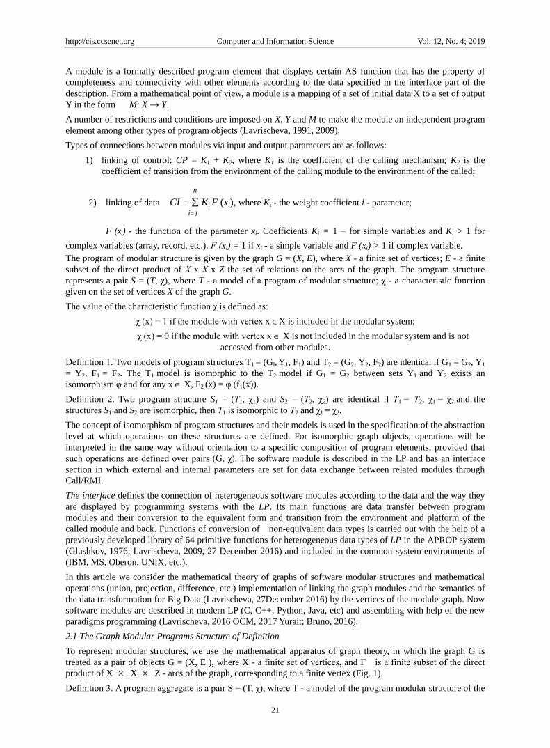
A module is a formally described program element that displays certain AS function that has the property of
completeness and connectivity with other elements according to the data specified in the interface part of the
description. From a mathematical point of view, a module is a mapping of a set of initial data X to a set of output
Y in the form M: X → Y.
A number of restrictions and conditions are imposed on X, Y and M to make the module an independent program
element among other types of program objects (Lavrischeva, 1991, 2009).
Types of connections between modules via input and output parameters are as follows:
1) linking of control: CP = K1 + K2, where K1 is the coefficient of the calling mechanism; K2 is the
coefficient of transition from the environment of the calling module to the environment of the called;
n
2) linking of data CI = Ki F (xi), where Ki - the weight coefficient i - parameter;
i=1
F (xi) - the function of the parameter xi. Coefficients Ki = 1 – for simple variables and Ki > 1 for
complex variables (array, record, etc.). F (хi) = 1 if xi - a simple variable and F (xi) > 1 if complex variable.
The program of modular structure is given by the graph G = (X, E), where X - a finite set of vertices; E - a finite
subset of the direct product of Х х Х х Z the set of relations on the arcs of the graph. The program structure
represents a pair S = (T, χ), where T - a model of a program of modular structure; χ - a characteristic function
given on the set of vertices X of the graph G.
The value of the characteristic function χ is defined as:
χ (x) = 1 if the module with vertex x X is included in the modular system;
χ (x) = 0 if the module with vertex x X is not included in the modular system and is not
accessed from other modules.
Definition 1. Two models of program structures Т1 = (Gl, Y1, F1) and Т2 = (G2, Y2, F2) are identical if G1 = G2, Y1
= Y2, F1 = F2. The Т1 model is isomorphic to the Т2 model if G1 = G2 between sets Y1 and Y2 exists an
isomorphism φ and for any х X, F2 (x) = φ (f1(x)).
Definition 2. Two program structure S1 = (Т1, χ1) and S2 = (Т2, χ2) are identical if Т1 = Т2, χ1 = χ2 and the
structures S1 and S2 are isomorphic, then Т1 is isomorphic to Т2 and χ1 = χ2.
The concept of isomorphism of program structures and their models is used in the specification of the abstraction
level at which operations on these structures are defined. For isomorphic graph objects, operations will be
interpreted in the same way without orientation to a specific composition of program elements, provided that
such operations are defined over pairs (G, χ). The software module is described in the LP and has an interface
section in which external and internal parameters are set for data exchange between related modules through
Call/RMI.
The interface defines the connection of heterogeneous software modules according to the data and the way they
are displayed by programming systems with the LP. Its main functions are data transfer between program
modules and their conversion to the equivalent form and transition from the environment and platform of the
called module and back. Functions of conversion of non-equivalent data types is carried out with the help of a
previously developed library of 64 primitive functions for heterogeneous data types of LP in the APROP system
(Glushkov, 1976; Lavrischeva, 2009, 27 December 2016) and included in the common system environments of
(IBM, MS, Oberon, UNIX, etc.).
In this article we consider the mathematical theory of graphs of software modular structures and mathematical
operations (union, projection, difference, etc.) implementation of linking the graph modules and the semantics of
the data transformation for Big Data (Lavrischeva, 27December 2016) by the vertices of the module graph. Now
software modules are described in modern LP (C, C++, Python, Java, etc) and assembling with help of the new
paradigms programming (Lavrischeva, 2016 OCM, 2017 Yurait; Bruno, 2016).
2.1 The Graph Modular Programs Structure of Definition
To represent modular structures, we use the mathematical apparatus of graph theory, in which the graph G is
treated as a pair of objects G = (X, E ), where X - a finite set of vertices, and Г is a finite subset of the direct
product of X X Z - arcs of the graph, corresponding to a finite vertex (Fig. 1).
Definition 3. A program aggregate is a pair S = (T, χ), where T - a model of the program modular structure of the
Page 3
http://cis.ccsenet.org Computer and Information Science Vol. 12, No. 4; 2019
22
aggregate; χ - a characteristic function defined on the set of vertices X of the graph of the modular structure G.
The value of the χ function is defined as follows:
χ(x) = 1 if the module corresponding to the vertex х X, - included in the unit;
χ(x) = 0 if the module corresponding to the vertex х X, - not included in the software unit, but it
is accessed from other modules previously included.
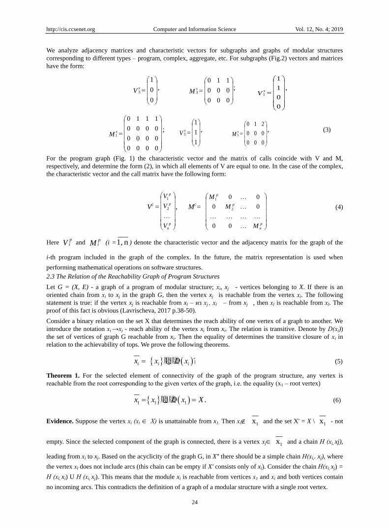
Figure 1. Graph from modules
The set of arcs of the graph have the form: E = {(x1, х2, 1), (xl, х3, 1), (х5, x8, 1), (х5, х8, 2)}. Based on this
definition, we can say that the graph G is a multi-graph, since its two vertices can be connected by several arcs.
To distinguish these arcs introduced their numbering positive integers – 1, 2. (Fig.1) and vertices of the graph x1,
х2, … , х8 form a set of X. From the module corresponding to the vertex х5, there are two link to the modules,
with vertices х7, х8.
Definition 4. The model of the program structure of the program unit is an object described by the triple T = (G,
Y, F), where G = (X, E) - a directed graph of a modular structure;
Y is a set of modules included in the program aggregate;
F is a correspondence function that puts an element of the set y at each vertex X of the graph.
Function F maps X to Y, F: X →Y. (1)
In General, an element from Y can correspond to several vertices from the set X, which is typical for the
dynamic structure of the aggregate (Lavrischeva, 2009, 2014).
The graph of software aggregates has the following properties:
1) graph G has one or more connectivity elements, each of which represents an acyclic graph, i.e. does not
contain oriented cycles;
2) in each graph G is allocated a single vertex, which is called the root and is characterized by the fact that
there are no arcs included in it and the corresponding module of the software unit is performed first;
3) cycles are allowed only for the case when some vertex has a recursive reference to itself. Typically, this
feature is implemented by the compiler with the corresponding LP and this type of communication is not
considered by the intermodule interface. Therefore, such arcs are not included in the graph. The exception to the
consideration of other types of cycles is due to the fact that some modules will have to remember the history of
their calls in order to return control correctly, which contradicts the properties of the modules;
4) an empty graph G0 corresponds to an empty program structure.
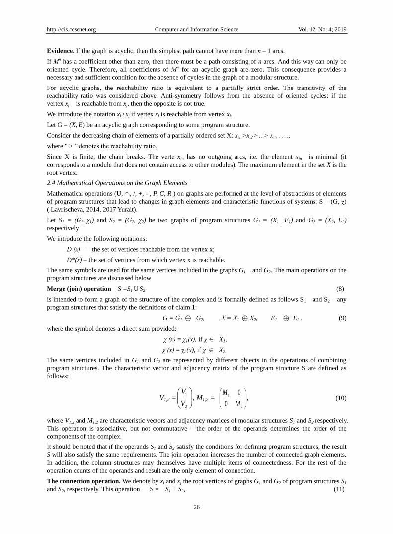
Next, the graph G will be used to illustrate mathematical operations on modular structures. In Figure 2, three
types of subgraphs are shown and their description is given.
Figure 2. The graphs of modules structures x1, x3, x5
Page 4
http://cis.ccsenet.org Computer and Information Science Vol. 12, No. 4; 2019
23
A subgraph - a fragment of a software aggregate Gs = (Xs, Es) for whose functions one of two conditions S is
satisfied:
C (S) = 1, if χ(x) = 1 for any vertex x of X;
C (S) = 0, if there is x such that χ(x) = 0;
R (Ss) = 0, if the modular structure is part of a higher-level structure and R(S) =1 if the software
assembly is ready to run.
Given these combinations C and R, the subgraph can be: open (C =0, R = 0); closed at the top (C = 0, R= 1);
closed at the bottom (C = 1, R = 0).
The graph of the module is represented as Gm = (Хт, Eт). It contains a single vertex хХт for which χ(xj)=1.
This vertex is the root. An arc of the form (хj, хе, k) means calling the module to the corresponding vertex хj, i.e.
to the module with the vertex xl. The dark circle on the graph corresponds to the vertex for which χ(x) = 1; light
– χ(x)=0.
Program graph Gp = (Хр, Ep) which is performed С (Sp) = 1; R (Sp) = 1. An example of a graph of such a program
modular structure is shown in Fig. 1.
The graph of the complex Gc= (Xc, Ec) consists of n connectivity components (n > 1), each of which is a graph
and includes: Gc=G
p1 G
p2 ,…, G
pn ,
where Xc = X
p1 X
p2 ,…, X
pn и Ec = Ep E1
p E1
p E2p ,…, En
p.
These definitions of the graph of the program module, program, aggregate and complex are used for the process
of assembling the modules. These concepts may differ from similar ones, which are considered in other contexts
of the work.
2.2 Matrix Representation of the Graph from Program Elements of Module Type
Graph theory is used in information technology (for example, in solving problems of control, communication,
design of electrical circuits, programming of complex program structures, etc.). To compile an algorithm for
solving problems on graph structures, reachability (incidence) and adjacency matrices are used. The incidence
matrix is of size n x m, where n is the number of vertices of the graph, m is the number of edges of the graph.
The matrix adjacencies correspond to vertices and columns to edges of the graph. The adjacency matrix allows
establishing a set of vertices adjacent to a given vertex and is represented by a two - dimensional array of size n
x n, where n is the number of vertices of the graph (Lavrischeva, 1991, 2009).
To determine the main operations on software structures, we use these mathematical apparatus of the matrix
representation of graphs in the form of an adjacency and reachability matrix. That is, the graph (fig.1) is
represented by the matrix M= m (i, j) of adjacency and is proved by the reach ability matrix (Evstigneev, 1985;
Lavrischeva, 2017; Theory Graphs, wiki). The element of the matrix тij determines the number of call
operators with index i, to the module with index j.
In addition to the adjacency matrix (calls), the characteristic vector Vi = χ (xi) for i-element is used. For a
modular structure graph (Fig. 1) characteristic vector and adjacency matrix have the form:
V =
1
1
1
1
1
1
1
1
M =
00000000
00000000
00000000
21000000
00100000
00110000
00000000
00001110
(2)
Page 5
http://cis.ccsenet.org Computer and Information Science Vol. 12, No. 4; 2019
24
We analyze adjacency matrices and characteristic vectors for subgraphs and graphs of modular structures
corresponding to different types – program, complex, aggregate, etc. For subgraphs (Fig.2) vectors and matrices
have the form:
0
0
1
3Vs ,
000
000
110
3Ms ;
0
0
1
1
1Vs
,
0000
0000
0000
1110
1Ms ;
1
1
1
5Vs ,
000
000
210
5Ms , (3)
For the program graph (Fig. 1) the characteristic vector and the matrix of calls coincide with V and M,
respectively, and determine the form (2), in which all elements of V are equal to one. In the case of the complex,
the characteristic vector and the call matrix have the following form:
Vc =
p
n
p
p
V
V
V
2
1
, Mc=
p
n
p
p
M
M
M
00
00
00
2
1
(4)
Here Vpi and M
pi (i = n 1, ) denote the characteristic vector and the adjacency matrix for the graph of the
i-th program included in the graph of the complex. In the future, the matrix representation is used when
performing mathematical operations on software structures.
2.3 The Relation of the Reachability Graph of Program Structures
Let G = (X, E) - a graph of a program of modular structure; хi, xj - vertices belonging to X. If there is an
oriented chain from хi to xj in the graph G, then the vertex xj is reachable from the vertex хi. The following
statement is true: if the vertex xj is reachable from xl – из хj , хl – from xj , then хl is reachable from хl. The
proof of this fact is obvious (Lavrischeva, 2017 p.38-50).
Consider a binary relation on the set X that determines the reach ability of one vertex of a graph to another. We
introduce the notation хi →хj - reach ability of the vertex xj from xi. The relation is transitive. Denote by D(хi))
the set of vertices of graph G reachable from xi. Then the equality of determines the transitive closure of хi in
relation to the achievability of tops. We prove the following theorems.
牋牋 ?i i ix х D x (5)
Theorem 1. For the selected element of connectivity of the graph of the program structure, any vertex is
reachable from the root corresponding to the given vertex of the graph, i.e. the equality (х1 – root vertex)
11 1牋牋 .х D xx X (6)
Evidence. Suppose the vertex хi (хi Х) is unattainable from x1. Then хi 1x and the set X' = X \
1x - not
empty. Since the selected component of the graph is connected, there is a vertex хj 1x and a chain Н (хi, xj),
leading from хi to xj. Based on the acyclicity of the graph G, in X'' there should be a simple chain Н(хi,. xj), where
the vertex хl does not include arcs (this chain can be empty if X' consists only of xi). Consider the chain Н(xl, xj) =
Н (xl, xi) U Н (xi, xj). This means that the module xi is reachable from vertices х1 and хi and both vertices contain
no incoming arcs. This contradicts the definition of a graph of a modular structure with a single root vertex.
Page 6
http://cis.ccsenet.org Computer and Information Science Vol. 12, No. 4; 2019
25
The theorem is proved.
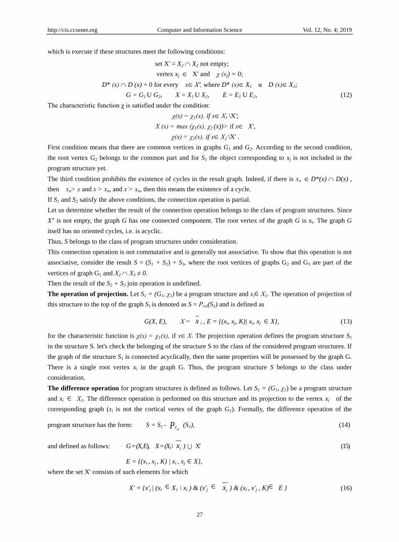
Figure 3. A graph that contain cycle
The results of this theorem are important to substantiate the requirement of the absence of oriented cycles in the
graph of the program structure with respect to the notion of reachability. Consider the graph shown in Fig. 3.
From this figure it is clear that the graph contains a directed cycle and modules corresponding to vertices х4, х5,
х6 will never be executed.
Thus, the results of theorem1 reinforce the requirement that there are no oriented cycles in the graph of the
program structure. We analyze the matrix representation of the reach ability relation for the graph of the program
structure Fig.1 with the reach ability matrix A, which has the form (7). Coefficient aij = 1 if the module
corresponding to the index l is reachable from the module corresponding to the index i the Following results are
based on the following theorem from graph theory.
А=
00000000
00000000
00000000
11000000
00100000
11110000
00000000
11111110
87654321 xxxxxxxx
(7)
Theorem 2. The coefficient mij of the l-th degree of the adjacency matrix Мl determines the number of different
routes containing l arcs and connecting vertex xi to the vertex of the xj –oriented graph. The proof of this
theorem is given in (Lavrischeva, 2017). Consider the following three consequences of this theorem.
Corollary 1.1. Matrix M =
n
l 1
Мi , where M is the adjacency matrix of a directed graph with n vertices
coincides up to the numerical values of the coefficients with the reachability matrix A.
Evidence. In a directed graph containing n vertices, the maximum path length without repeating arcs cannot
exceed n. Therefore, the sequence of degrees of the adjacency matrix Mi, where i = 1,2, ..., n determines the
number of all possible paths in the graph with the number of arcs ≤ p. Let the coefficient ijm of the matrix M
be different from zero. This means that there is a degree of matrix Мi in which the corresponding coefficient
ijm is also nonzero. Therefore, there is a path from vertex xi to xj, i.e. vertex xj is reachable from xi. This
consequence determines the connection of the matrix of calls of the graph of the modular structure M, coinciding
with the reachability matrix A, and determines the algorithm for constructing the latter.
Corollary 1.2. Let there be a coefficient mii > 0 for some i in the sequence of degrees of the adjacency matrix Mi.
Then there is a cycle in the original graph.
Evidence. Let mii > 0 for some l. Therefore xl reachable from xi, i.e. there is a cycle. According to the theorem,
this cycle has l arcs (generally repeated).
Corollary 1.3. Let the n-th degree of the adjacency matrix of the Мп of the acyclic graph coincide with the zero
matrix (all coefficients are zero).
Page 7
http://cis.ccsenet.org Computer and Information Science Vol. 12, No. 4; 2019
26
Evidence. If the graph is acyclic, then the simplest path cannot have more than п – 1 arcs.
If Мп has a coefficient other than zero, then there must be a path consisting of n arcs. And this way can only be
oriented cycle. Therefore, all coefficients of Мп for an acyclic graph are zero. This consequence provides a
necessary and sufficient condition for the absence of cycles in the graph of a modular structure.
For acyclic graphs, the reachability ratio is equivalent to a partially strict order. The transitivity of the
reachability ratio was considered above. Anti-symmetry follows from the absence of oriented cycles: if the
vertex xj is reachable from xj, then the opposite is not true.
We introduce the notation xi>xj if vertex xj is reachable from vertex xi.
Let G = (X, E) be an acyclic graph corresponding to some program structure.
Consider the decreasing chain of elements of a partially ordered set X: xi1 >xi2 >…> xin . …,
where " > ‖ denotes the reachability ratio.
Since X is finite, the chain breaks. The verte xin has no outgoing arcs, i.e. the element xin is minimal (it
corresponds to a module that does not contain access to other modules). The maximum element in the set X is the
root vertex.
2.4 Mathematical Operations on the Graph Elements
Mathematical operations (U, , /, +, - , P, C, R ) on graphs are performed at the level of abstractions of elements
of program structures that lead to changes in graph elements and characteristic functions of systems: S = (G, χ)
( Lavrischeva, 2014, 2017 Yurait).
Let S1 = (G1, χ1) and S2 = (G2, χ2) be two graphs of program structures G1 = (Х1 , E1) and G2 = (X2, E2)
respectively.
We introduce the following notations:
D (х) – the set of vertices reachable from the vertex x;
D*(x) – the set of vertices from which vertex x is reachable.
The same symbols are used for the same vertices included in the graphs G1 and G2. The main operations on the
program structures are discussed below
Merge (join) operation S =S1 U S2 (8)
is intended to form a graph of the structure of the complex and is formally defined as follows S1 and S2 – any
program structures that satisfy the definitions of claim 1:
G = G1 G2, Х = Х1 Х2, E1 E2 , (9)
where the symbol denotes a direct sum provided:
χ (х) = χ1(х), if χ X1,
χ (х) = χ2(x), if χ Х2.
The same vertices included in G1 and G2 are represented by different objects in the operations of combining
program structures. The characteristic vector and adjacency matrix of the program structure S are defined as
follows:
V1,2 =
2
1
V
V, M1,2 =
2
1
0
0
M
M, (10)
where V1,2 and M1,2 are characteristic vectors and adjacency matrices of modular structures S1 and S2 respectively.
This operation is associative, but not commutative – the order of the operands determines the order of the
components of the complex.
It should be noted that if the operands S1 and S2 satisfy the conditions for defining program structures, the result
S will also satisfy the same requirements. The join operation increases the number of connected graph elements.
In addition, the column structures may themselves have multiple items of connectedness. For the rest of the
operation counts of the operands and result are the only element of connection.
The connection operation. We denote by xi and xj the root vertices of graphs G1 and G2 of program structures S1
and S2, respectively. This operation S = S1 + S2, (11)
Page 8
http://cis.ccsenet.org Computer and Information Science Vol. 12, No. 4; 2019
27
which is execute if these structures meet the following conditions:
set X' = X2 X2 not empty;
vertex xj X' and χ (хj) = 0;
D* (х) D (x) = 0 for every хХ', where D* (х)X1 и D (х)X2;
G = G1 U G2, X = X1 U X2, E = E1 U E2, (12)
The characteristic function χ is satisfied under the condition:
χ(х) = χ1(х), if хХ1 \X';
Х (х) = mах (χ1(х), χ2 (x))> if х X',
χ(х) = χ2(х), if хХ2 \X' .
First condition means that there are common vertices in graphs G1 and G2. According to the second condition,
the root vertex G2 belongs to the common part and for S1 the object corresponding to xj is not included in the
program structure yet.
The third condition prohibits the existence of cycles in the result graph. Indeed, if there is хп D*(x) D(x) ,
then хп> х and x > хn, and x > хn, then this means the existence of a cycle.
If S1 and S2 satisfy the above conditions, the connection operation is partial.
Let us determine whether the result of the connection operation belongs to the class of program structures. Since
X'' is not empty, the graph G has one connected component. The root vertex of the graph G is xi. The graph G
itself has no oriented cycles, i.e. is acyclic.
Thus, S belongs to the class of program structures under consideration.
This connection operation is not commutative and is generally not associative. To show that this operation is not
associative, consider the result S = (S1 + S2) + S3, where the root vertices of graphs G2 and G3 are part of the
vertices of graph G1 and Х2 Х3 ≠ 0.
Then the result of the S2 + S3 join operation is undefined.
The operation of projection. Let S1 = (G1, χ1) be a program structure and хiХ1. The operation of projection of
this structure to the top of the graph S1 is denoted as S = Рrxi(S1) and is defined as
G(X, E), Х = x i , E = {(xi, xj, K)| xi, xj X}, (13)
for the characteristic function is χ(х) = χ1(х), if хХ. The projection operation defines the program structure S1
in the structure S. let's check the belonging of the structure S to the class of the considered program structures. If
the graph of the structure S1 is connected acyclically, then the same properties will be possessed by the graph G.
There is a single root vertex xi in the graph G. Thus, the program structure S belongs to the class under
consideration.
The difference operation for program structures is defined as follows. Let S1 = (G1, χ1) be a program structure
and xi Х1. The difference operation is performed on this structure and its projection to the vertex xi of the
corresponding graph (хi is not the cortical vertex of the graph G1). Formally, the difference operation of the
program structure has the form: S = S1 - Pxir (S1), (14)
and defined as follows: G = (X, E), X = (X1 \ ix ) X' (15)
E = {(xi , xj , K) | xi , xj X},
where the set X' consists of such elements for which
X' = {x'j | (xl X1 \ xi ) & (x'j ix ) & (xl , x'j , K) E } (16)
Page 9
http://cis.ccsenet.org Computer and Information Science Vol. 12, No. 4; 2019
28
Here, the characteristic function χ is defined as:
χ(х) = χ1(х), если хХ1 \ ix ;
χ(х) = 0), если х X' .
The set X includes vertices that are not included in the set ix , and those vertices ix that include arcs from
vertex X1 \ ix (sets X'). The characteristic function for elements х' X' is zero. The difference operation is
the inverse of the join operation, i.e. the equality is performed: S - Pxir (S) + P
xir (S) = S. (17)
Let us check that S, defined in (15), belongs to the class of program structures. If the graph is G, connected and
acyclic, then the graph G1 will have the same properties. The root vertex G is the same as the root vertex G1.
Thus, S satisfies the conditions for determining the program structure given in paragraph 1.
Let S* be the set of program structures given by the direct product G* X χ*, where G* and χ* are the set of
graphs and the set of characteristic functions. Denote by Ω = {U, , /, +, -} - set of mathematical operations on
program structures and P, C and R - predicates of:
Ω = {U, , /, +, - , P, C, R}. (18)
Thus, an algebraic system = (S, Ω ) over a set of program structures and operations on them (union, connection,
differences and projections) is defined.
2.5 The Simple and Complex of Graph Structures Programs
Among the variety of program structures there are three main ones – a simple, complex structure with a call of
modules from the external environment and a dynamic structure. The main purpose of various structures is the
most optimal use of the main memory during the execution of the unit (Lavrischeva, 2014, 2017 Yurait).
Simple structure. An aggregate with a simple structure is created in the process of building modules based on
the operations of link calls. The amount of main memory occupied by an aggregate with a simple structure is
constant and equal to the sum of the volumes of individual modules:
Vs =
n
i
iv1
, where vi is the amount of memory occupied by the i-th module (i=n). The corresponding graph of
a modular structure is always connected.
Complex structure. Assembly of complex structures with dynamic invocation of modules in the shared memory
is created in the Assembly process of the modules. In such an aggregate, the connections between the modules
are not so rigid and their sequence is determined by the modules included in the chain. The modules are loaded
into the main memory at the time of processing. When finished, the memory is freed and used to load another
module. As in the case of a simple structure, the graph of a complex program structure is also connected (Fig.4)
and is reflected in the adjacency matrix (2).
x5
x6
x2
x3
x4
x7x8
x12
x10 x11
x1
1
1
11
1
1 1
1
1 1
1
1
1 2
x0
x9
Figure 4. Modification graph of program structure
The amount of main memory required depends on the number and composition of modules and the maximum
Page 10
http://cis.ccsenet.org Computer and Information Science Vol. 12, No. 4; 2019
29
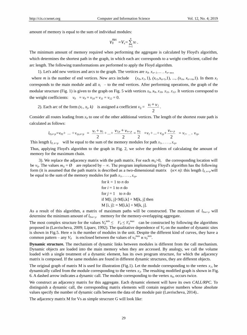
amount of memory is equal to the sum of individual modules:
vmax0 =Vs=
n
i
iv1
.
The minimum amount of memory required when performing the aggregate is calculated by Floyd's algorithm,
which determines the shortest path in the graph, in which each arc corresponds to a weight coefficient, called the
arc length. The following transformations are performed to apply the Floyd algorithm.
1). Let's add new vertices and arcs to the graph. The vertices are х0, хп+1,… , хп+m,,
where m is the number of end vertices. New arcs include (х0, х1, 1), (xr1,xn+1,1), ..., (xrn, xn+rn,1). In them x1
corresponds to the main module and all xi – to the end vertices. After performing operations, the graph of the
modular structure (Fig. 1) is given to the graph on Fig. 5 with vertices х0, x9, х10, х11, х12. It vertices correspond to
the weight coefficients: v0 = v9 = v10 = v11 = v12 = 0.
2). Each arc of the form (xi , xj, k) is assigned a coefficient vij = 2
vv ji .
Consider all routes leading from х0 to one of the other additional vertices. The length of the shortest route path is
calculated as follows:
l0,n+p=v01+ … +vrp,n+p = 2
10 vv +…+
2
2 vv pnp =
2
0v +v1 +…+vrp+
2
v pn = v1+ … + vrp.
This length l0, n+p will be equal to the sum of the memory modules for path х1, . . . , хrр.
Thus, applying Floyd's algorithm to the graph in Fig. 2, we solve the problem of calculating the amount of
memory for the maximum chain.
3). We replace the adjacency matrix with the path matrix. For each mij>0, the corresponding location will
be vij. The values тij = Ø are replaced by – ∞. The program implementing Floyd's algorithm has the following
form (it is assumed that the path matrix is described as a two-dimensional matrix (пn): this length l0, n+p will
be equal to the sum of the memory modules for path х1, . . . , хrр.
for k = 1 to n do
for i = 1 to n do
for j = 1 to n do
if M[i, j]<M[i,k] + M[k, j] then
M [i, j]: = M[i,k] + M[k, j].
As a result of this algorithm, a matrix of maximum paths will be constructed. The maximum of l0,п+p will
determine the minimum amount оf l0,п+p memory for the memory-overlapping aggregate.
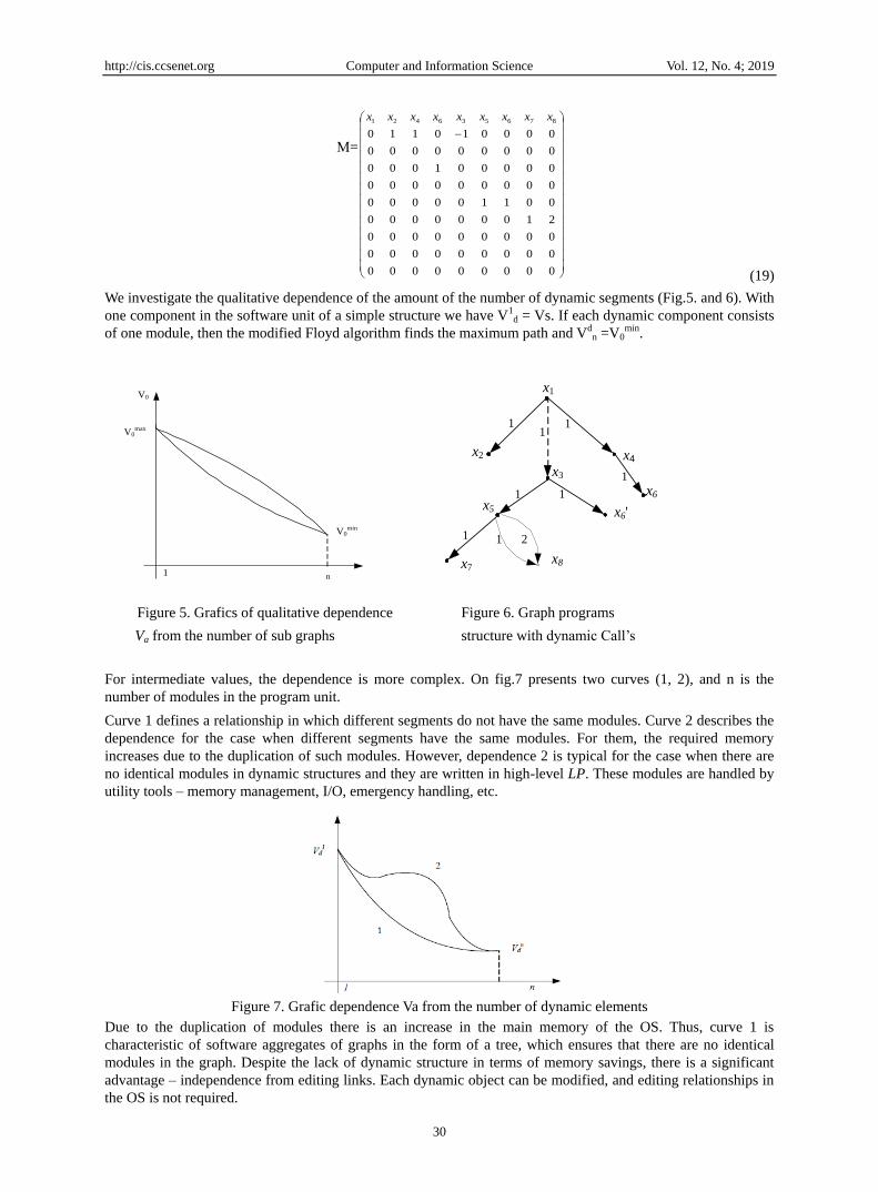
The most complex structure for the values V0min ≤ V0 ≤ V0
max can be constructed by following the algorithms
proposed in (Lavrischeva, 2009; Lipaev, 1992). The qualitative dependence of V0 on the number of dynamic sites
is shown in Fig.5. Here п is the number of modules in the unit. Despite the different kind of curves, they have a
common pattern – any V0 is enclosed between the values of v0max и v0
min.
Dynamic structure. The mechanism of dynamic links between modules is different from the call mechanism.
Dynamic objects are loaded into the main memory when they are accessed. By analogy, we call the volume
loaded with a single treatment of a dynamic element, has its own program structure, for which the adjacency
matrix is composed. If the same modules are found in different dynamic structures, they are different objects.
The original graph of matrix M is used for illustration (Fig.1). Let the module corresponding to the vertex х1, be
dynamically called from the module corresponding to the vertex х3. The resulting modified graph is shown in Fig.
6. A dashed arrow indicates a dynamic call. The module corresponding to the vertex x6, occurs twice.
We construct an adjacency matrix for this aggregate. Each dynamic element will have its own CALL/RPC. To
distinguish a dynamic call, the corresponding matrix elements will contain negative numbers whose absolute
values specify the number of dynamic calls between the data of the module pair (Lavrischeva, 2014)..
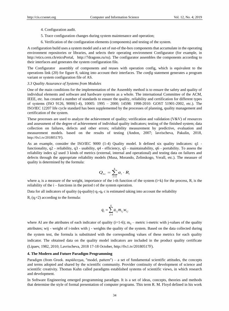
The adjacency matrix M for Vs as simple strucrure G will look like:
Page 11
http://cis.ccsenet.org Computer and Information Science Vol. 12, No. 4; 2019
30
М=
000000000
000000000
000000000
210000000
001100000
000000000
000001000
000000000
000010110
876536421 xxxxxxxxx
(19)
We investigate the qualitative dependence of the amount of the number of dynamic segments (Fig.5. and 6). With
one component in the software unit of a simple structure we have V1d = Vs. If each dynamic component consists
of one module, then the modified Floyd algorithm finds the maximum path and Vdn =V0
min.
n
V0
V0max
1
V0min
Figure 5. Grafics of qualitative dependence
Va from the number of sub graphs
x5
x2
x3
x4
x7x8
x6'
x1
1 11
1 1
1
21 1
x6
Figure 6. Graph programs
structure with dynamic Call’s
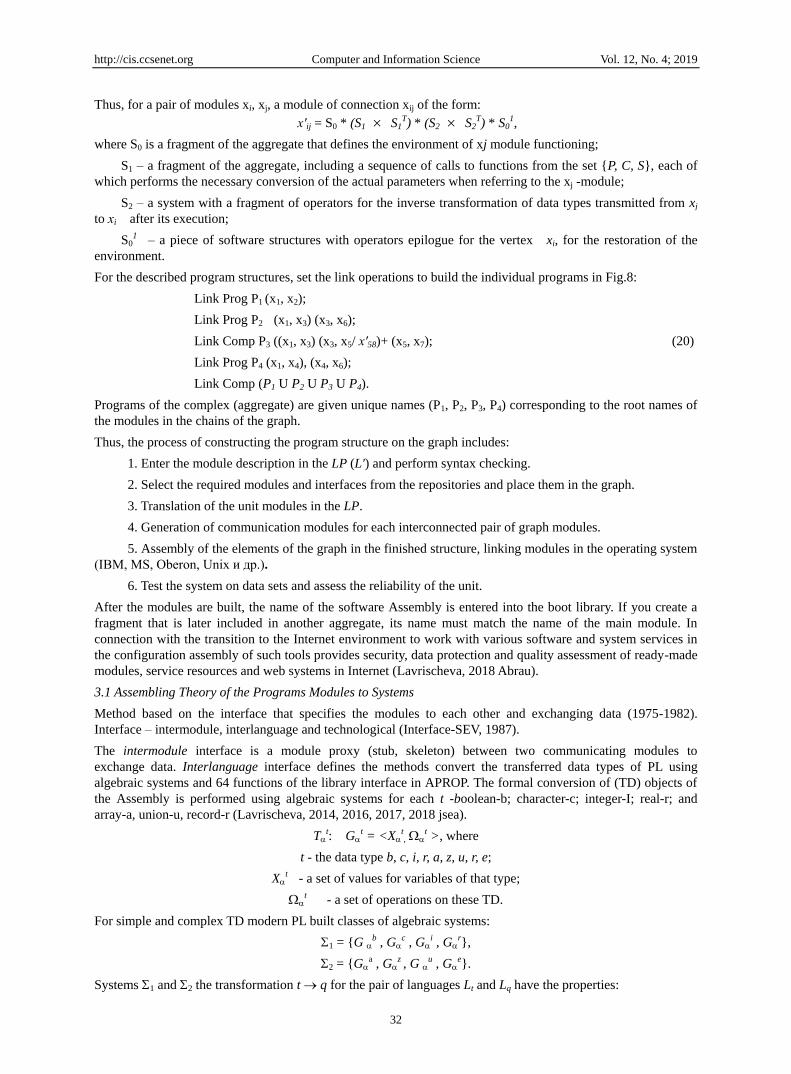
For intermediate values, the dependence is more complex. On fig.7 presents two curves (1, 2), and n is the
number of modules in the program unit.
Curve 1 defines a relationship in which different segments do not have the same modules. Curve 2 describes the
dependence for the case when different segments have the same modules. For them, the required memory
increases due to the duplication of such modules. However, dependence 2 is typical for the case when there are
no identical modules in dynamic structures and they are written in high-level LP. These modules are handled by
utility tools – memory management, I/O, emergency handling, etc.
Figure 7. Grafic dependence Va from the number of dynamic elements
Due to the duplication of modules there is an increase in the main memory of the OS. Thus, curve 1 is
characteristic of software aggregates of graphs in the form of a tree, which ensures that there are no identical
modules in the graph. Despite the lack of dynamic structure in terms of memory savings, there is a significant
advantage – independence from editing links. Each dynamic object can be modified, and editing relationships in
the OS is not required.
Page 12
http://cis.ccsenet.org Computer and Information Science Vol. 12, No. 4; 2019
31
3. Operations of Assembling Programs Elements of Graph
Let the graph G be represented by the set of modules Х= {х1, х2, ..., хт}, as described in LP, and located at the
vertices of the graph. The modules are assembled into a software unit. In this case, each pair of modules хi, хj (i, j
– languages from the set of LP are connected by the relation of call on the basis of which the module of
communication х'ij is formed. In General, for simple program structures, the aggregate contains link
communication (call) operators and forward and reverse transformations of data types passed from the calling
module (in i-language) to the calling module (in j-language) and back (Lavrischeva, 2014, 2016, 2017).
After 1992 it are for link equivalent operations: make BSD, Java (1996); assembling, config SPAROL, Grid
(2002), etc. (Lavrischeva, 2017, 2018 OS Day; 2018 Jsea). Then there were standard languages of the
description of interfaces of IDL, API, WSDL and the statement of config of the standard IEEE 828-2012
(Configuration Management) for receiving a configuration file of any AS from modules, objects, components,
services and other the ready resources in new LP.
LP allows you to describe the information part - passport modules with a description of the transmitted data
(Lavrischeva, 2016; 2016, 27December; 2018 jsea) and operations call modules. Taking into account the
passports of the modules, the software structure of the unit is built (program - Prog, complex - Comp, package -
Pac). The passport describes the special language WSDL containing: a subset of the operations associate link
elements of the graph in the language L' that contains a description of the parameters from the list of actual and
formal parameters of the invocation; mathematical operations on the graph and operations of linking modules.
The operator modules link (make, config, assembling, etc) takes the general form:
link <aggregate type> <aggregate name> (<main module name>, <additional list of module names>)
<execution mode>, when constructing specific program structures, the vertices of the graph – modules can be
marked with special symbols ρ, denoting:
ρ = ¤ formation of a fragment with the name of the module;
ρ = * the beginning of the dynamic fragment with the vertex marked by this symbol;
ρ = + the module in the graph G is marked as the main program of the complex;
ρ = / means enabling debugging or testing of the unit.
Using these designations, the graph G will take the form shown in figure 8 and has a representation:
E = {(х5,х7,1), (х5,x8,1), (x5,х8,2)}.
The aggregate is given a unique name corresponding to the generated root module. For the graph E = {(х4, х6, 1)}
a fragment of operators providing a dynamic call will be formed in the communication module x'46. For a pair of
modules specified in Fig.8 vertices x4, x6, the structure of the corresponding part of the unit, including the
communication module, is shown in Fig. 9. Similarly links of heterogeneous modules and other types of calls are
implemented.
¤x5
+x2
x3
*x4
x7 x8
x6
x1
1 11
1 1
1
21 1
Figure 8. Graph of software unit with control
marks on the graph
x4
S0
Link P x6
S1Т
S1
x6
S2
S01
Call P x4
X’46
Figure 9. Graph of modular structure with dynamic
calls (Lavrischeva, 1982)
Page 13
http://cis.ccsenet.org Computer and Information Science Vol. 12, No. 4; 2019
32
Thus, for a pair of modules xi, xj, a module of connection xij of the form:
х'ij = S0 * (S1 S1T) * (S2 S2
T) * S01,
where S0 is a fragment of the aggregate that defines the environment of xj module functioning;
S1 – a fragment of the aggregate, including a sequence of calls to functions from the set {P, C, S}, each of
which performs the necessary conversion of the actual parameters when referring to the xj -module;
S2 – a system with a fragment of operators for the inverse transformation of data types transmitted from xj
to хi after its execution;
S01 – a piece of software structures with operators epilogue for the vertex xi, for the restoration of the
environment.
For the described program structures, set the link operations to build the individual programs in Fig.8:
Link Prog P1 (x1, x2);
Link Prog P2 (x1, x3) (x3, x6);
Link Comp P3 ((x1, x3) (x3, x5/ х'58)+ (x5, x7); (20)
Link Prog P4 (x1, x4), (x4, x6);
Link Comp (P1 U P2 U P3 U P4).
Programs of the complex (aggregate) are given unique names (P1, P2, P3, P4) corresponding to the root names of
the modules in the chains of the graph.
Thus, the process of constructing the program structure on the graph includes:
1. Enter the module description in the LP (L') and perform syntax checking.
2. Select the required modules and interfaces from the repositories and place them in the graph.
3. Translation of the unit modules in the LP.
4. Generation of communication modules for each interconnected pair of graph modules.
5. Assembly of the elements of the graph in the finished structure, linking modules in the operating system
(IBM, MS, Oberon, Unix и др.).
6. Test the system on data sets and assess the reliability of the unit.
After the modules are built, the name of the software Assembly is entered into the boot library. If you create a
fragment that is later included in another aggregate, its name must match the name of the main module. In
connection with the transition to the Internet environment to work with various software and system services in
the configuration assembly of such tools provides security, data protection and quality assessment of ready-made
modules, service resources and web systems in Internet (Lavrischeva, 2018 Abrau).
3.1 Assembling Theory of the Programs Modules to Systems
Method based on the interface that specifies the modules to each other and exchanging data (1975-1982).
Interface – intermodule, interlanguage and technological (Interface-SEV, 1987).
The intermodule interface is a module proxy (stub, skeleton) between two communicating modules to
exchange data. Interlanguage interface defines the methods convert the transferred data types of PL using
algebraic systems and 64 functions of the library interface in APROP. The formal conversion of (TD) objects of
the Assembly is performed using algebraic systems for each t -boolean-b; character-c; integer-I; real-r; and
array-a, union-u, record-r (Lavrischeva, 2014, 2016, 2017, 2018 jsea).
Tt: G
t = <Xt,
t >, where
t - the data type b, c, i, r, a, z, u, r, e;
Xt - a set of values for variables of that type;
t - a set of operations on these TD.
For simple and complex TD modern PL built classes of algebraic systems:
1 = {G b , G
c , Gi , G
r},
2 = {Ga , G
z , G u , G
e}.
Systems 1 and 2 the transformation t q for the pair of languages Lt and Lq have the properties:
Page 14
http://cis.ccsenet.org Computer and Information Science Vol. 12, No. 4; 2019
33
1) Gt and G
q – isomorphic to q and t defined on the same set;
2) Xt and X
q are isomorphic if t and
q are different. If = t
q is not empty, then there
is a isomorphism between G t = < X
t , > и Gq = < X
q , >.
3) Between the sets Xt and X
q may not be isomorphic matching, then build such a mapping between
Xt and X
q that it is isomorphic.
Theorem. Let – displays the algebraic system Gс to G
с. In order to be an isomorphism, it is
necessary and sufficient to isomorphic reflected Xс and X
с, preserving linear order.
Each class of systems transformation t q for the pair of languages lq and lt of PL may be some
properties of mappings:
- systems Gt and G
q are isomorphic if their q, t are defined on the same set TD;
- between the values of Xt and X
q of data types t, q there is an isomorphism if the set of operations
t and
q are different;
- if the set = t
q is not empty, then we have the isomorphism of the two systems Gt = < G
t
= < Xt ,> и G
q = < Xq , >.
If data types are different, for example, t - string, and type q is real, then there is no isomorphic
correspondence between sets Xt и X
q.
The maps preserve the linear order of the elements based on the linear order of the elements of the
algebraic systems of these classes.
These methods put on the beginning assemble programming in USSR (Lavrischeva, 1982, 1991; Lipaev, 1992).
Operations assembling after 1990
Languages for describing object links in different environments it was such: make GNU, BSD, Java (1996);
config, building, assembling Grid (2002), etc. (Lavrischeva, 2009, 2014, 2017). The make statement by
RPC/RMI provides Assembly of executable modules from Filemake libraries and sets them the order of links
with each other in Linux, BSD, GNU, Java, Grid and other (http://xrnlrpc.scripting.corn/spec.html).
Operators config, building, assembling worked out in the European Grid project. Further development of the
Assembly was factory programs (D. Greenfield and K. Lenz – stream Assembly 2007; K, A. Chernetsky and
Azinaker – multy-conveyor 2005; I. Bay – the interaction of multi-language programs in distributed
environments, 2005; R. Pohle - conveyor Assembly for Product Line/Product Family, 2004, etc.).
The theory of factories on a method of Assembly for production of programs from ready reuses with processes
of planning, management, estimation of cost and quality of a product was formed. In 2012, the Assembly
(integration) of ready-made reuses was standardized in IEEE 828-96, 2012 (Configuration Management) to
obtain the configuration file of any application system from ready-made resources (Lavrischeva, 2015 London;
2017 29-30 November; 2017 IEEE).
3.2 Ready-Made Software Elements (Reuses) Configuration to the System
Under the configuration of the system is understood the structure of some of its version, including software
elements, combined with each other by link operations with parameters that specify the options for the
functioning of the system (Lavrischeva, 2018 jsea; 2018 Abrau). Version or variant of system configuration
according to the IEEE Standard 828-2012 (Configuration) includes:
– configuration basis (BC);
– Configuration items;
– program elements (modules, components, services, etc.) included in the graph;
Configuration Management is to monitor the modification of configuration parameters and components of the
system, as well as to conduct system monitoring, accounting and auditing of the system, maintaining the
integrity and its performance. According to the standard, the configuration includes the following tasks:
1. Configuration identification.
2. Configuration Control.
3. Configuration Status Accounting.
Page 15
http://cis.ccsenet.org Computer and Information Science Vol. 12, No. 4; 2019
34
4. Configuration audit.
5. Trace configuration changes during system maintenance and operation;
6. Verification of the configuration elements (components) and testing of the system.
A configuration build uses a system model and a set of out-of the-box components that accumulate in the operating
environment repositories or libraries, and selects their operating environment Configurator (for example, in
http://etics.cern.ch/eticsPortal, http://7dragons.ru/ru). The configurator assembles the components according to
their interfaces and generates the system configuration file.
The Configurator assembly of components and reuses with operation config, which is equivalent to the
operations link (20) for figure 8, taking into account their interfaces. The config statement generates a program
variant or system configuration file of AS.
3.3 Quality Assurance of Systems from Modules
One of the main conditions for the implementation of the Assembly method is to ensure the safety and quality of
individual elements and software and hardware systems as a whole. The international Committee of the ACM,
IEEE, etc. has created a number of standards to ensure the quality, reliability and certification for different types
of systems (ISO 9126, 9000(1-4), 10005: 1995 – 2000; 14598: 1998-2010: GOST 51901-2002, etc.). The
ISO/IEC 12207 life cycle standard has been supplemented by the processes of planning, quality management and
certification of the system.
These processes are used to analyze the achievement of quality; verification and validation (V&V) of resources
and assessment of the degree of achievement of individual quality indicators; testing of the finished system; data
collection on failures, defects and other errors; reliability measurement by predictive, evaluation and
measurement models. based on the results of testing (Andon, 2007; lavrischeva, Pakulin, 2018,
http://0x1.tv/20180517F).
As an example, consider the ISO/IEC 9000 (1-4) Quality model. It defined six quality indicators: q1 -
functionality, q2 - reliability, q3 - usability, q4 - efficiency, q5 - maintainability, q6 - portability. To assess the
reliability index q2 used 3 kinds of metrics (external, internal and operational) and testing data on failures and
defects through the appropriate reliability models (Musa, Morando, Zelinskogo, Verall, etc.). The measure of
quality is determined by the formula:
where ai is a measure of the weight, importance of the i-th function of the system (i=k) for the process, Ri is the
reliability of the i – functions in the period t of the system operation.
Data for all indicators of quality (q-quality) q1-q6 c is estimated taking into account the reliability
Ri (qi=2) according to the formula:
where AI are the attributes of each indicator of quality (i=1-6); mij – metric i-metric with j-values of the quality
attributes; wij - weight of i-index with j - weights the quality of the system. Based on the data collected during
the system test, the formula is substituted with the corresponding values of these metrics for each quality
indicator. The obtained data on the quality model indicators are included in the product quality certificate
(Lipaev, 1982, 2010; Lavrischeva, 2018 17-18 October, http://0x1.tv/20180517F).
4. The Modern and Future Paradigm Programming
Paradigm (from Greek. παράδειγμα, "model, pattern") – a set of fundamental scientific attitudes, the concepts
and terms adopted and shared by the scientific community. Provider continuity of development of science and
scientific creativity. Thomas Kuhn called paradigms established systems of scientific views, in which research
and development.
In Software Engineering emerged programming paradigm. It is a set of ideas, concepts, theories and methods
that determine the style of formal presentation of computer programs. This term R. M. Floyd defined in his work
jj
j
j wmaq 11
6
1
11
i
k
i
iпс RaQ 1
Page 16
http://cis.ccsenet.org Computer and Information Science Vol. 12, No. 4; 2019
35
"The Paradigms of Programming" (Communications of the ACM. 1969. V. 22 (8). P. 455-460) and E. Dijkstra in
the book "Discipline of programming" (M.: Mir, 1976) And D. Gris in the book "Science of programming".
Paradigms it is a method of conceptualization and formal definition of programs and systems. Some parts of the
theory are implemented in the framework of applied (functional, logical, automatic, etc.), theoretical (VDM,
OOP, Z, B, OCM, FODA, etc.), system types (parallel, distributed, etc.) and commercial (Agile, SCRUM, EX)
programming (Lavrischeva, 2017 Yurait).
4.1 Theoretical Programming Paradigms
Theory of graphs for design software modular structures with mathematical operations (union, projection,
difference, etc.) implementation of linking the graph modules (objects) and the semantics of the transformation
of data transmitted by the vertices of the graph G (Lavrischeva,1991, 2014, 2018 jsea). .
Object-component methods - OCM
OCM are the mathematical design of systems from ready-made resources (objects, components, services, etc.) to
OM (Object Model). It is the formal method which transform the elements OM to a component model or a
service model (Lavrischeva, 2016 OCM, 2018 ISP , http://0x1.tv/20181122AF ).
Graph objects is designed on four levels:
Generalizing for determining SD base notions without considering of their essences and properties;
Structuring for ordering objects in the OM taking into account relationships between them;
Characterization for forming concepts of objects on the base of them properties and descriptions;
Behavioral level for descriptions of conduct depending on events (such as time).
That is, vertices of the graph G are objects of two types: O= (О0, O1, O2. On) with the object relations hold
)()0( 0OOii i and interface objects I (Fig.10).
O1
O2 O3 O4
O25
O5 O6 O7 O8
O26 O47 O48
objects functions
interface objects
objects from repositoty
Figure 10. Object-interface graph G
At the vertices of a graph G contains the functional objects О1, О2, О3, О4, О5, О6, О7, О8 and interface objects
—0’25, O’26, O’47, O’48, which are placed in the repository of system, and arcs correspond to relationships
between all kinds of objects (Lavrischeva, 2014 jsea, 2016). The parameters of the external characteristics of
the interface objects are passed between objects through specified interfaces and are designated in language IDL
in (input interface), out (output) and inout (intermediate). Based on the graph G we can construct a program P0
— P5 using mathematical operation Assembly link:
1) P0 = (P1 P2 P3 P4 P5).
2) P1 = О2 О5 , link P1 =In O’5 (О2 О5);
3) P2 = О2 О6, link P2 =In O’6 (О2 О8);
4) P3;
5) P4 = О4 О7, link P4 =In O’7 (О4 О7);
6) P5 = О4 О8, link P4 =In O’8 (О4 О8);
The set of objects and interfaces of the graph is reflected by general or individual properties and descriptions of
the object model. Verification of properties of objects is provided by the specific operations (classification,
Page 17
http://cis.ccsenet.org Computer and Information Science Vol. 12, No. 4; 2019
36
specialization, aggregation, etc.).
Component paradigm. The basis of this paradigm - OCM graph in which vertexes are the components of the
CRP (reuses), interfaces and arcs specify the subject classification and the relationship between the vertices.
Components are described by the formalisms of the triangle of Frege (Lavrischeva, 2014jsea, 2016, 2018
IJANS).
- sign – identifier of the real function entity;
- denotation – the designation of this entity;
- concept – a set of properties defined by logical connections and must be true. Operations of OCM and
component algebra represented on the website http://7dragons/ru/ru (in the VS environment – MS, IBMSphere,
Java, Linux, Intel etc.).
Service-component paradigm. System and service-components - web resources implement intellectual
knowledge of specialists about applied fields in the Internet environment (Lavrischeva, 2017). Each implements
some function and communicates with the technological interface to interact with other services through
protocols and provide Assembly and solution of applications of different nature. The means of describing the
application systems include:
XML for description and construction of SSA components;
WSDL to describe web services and their interfaces;
SOAP to determine the formats of requests to the web services;
UDDI for integration of services and their storage in libraries;
Configuration (config) of the service resources in some high-quality and secure.
The theory of graphs develop in the school of A.P. Ershov (V.I. Kasyanov, V.E. Itkin, A. A. Evstigneev et al.) for
programming Systems. The graph theory has been actively developing in the Russian Academy of Sciences
(Lavrischeva, 2017; http://0x1.tv/20181122AF). The theory of conformity for systems with blocking and
destruction for the schematic organization of memory in Linux.
Methods of production of factories (Product Line/Product Family) programs and Appfab and certificate them of
the quality are discussed (Lavrischeva, 2011, 2013 com, 2014, 2017).
Application of the ontology language OWL (www.semantic_web.com), resource language (RDF) and intelligent
agents of ISO 15926 standard for networking.
Ontology of Life Cycle and Computational geometry is a part of computer graphics and algebra. Used in the
practice of computing and control machines, numerical control etc. is also used in robotics (motion planning and
pattern recognition tasks), geographic information systems (geometric search, route planning), design chips, etc.
(Lavrischeva, 2014, 2015, 2017 Yurayt).
Cloud technologies (PaaS, SaaS) are related to the Internet and are used to create adaptive applications that
interact through agents of web pages (Lavrischeva, 2014, 2017, 2018).
Device configuring Big Data Processing Devices (Big Data) in Smart Data Internet 4.0 (Lavrischeva, 2016,
2018).
4.2 Application Technical Programming
Event management paradigm based on the processing of external events (event-driven programming) in the
Window environment. Features of the event paradigm are the use of testing methods based on operational
(scenario) profiles of programs (Andon, 2007).
Coordinated and parallel programming provides a division of the computational process into several subtasks
(processes) for TRAN’s computers and supercomputers, the results of which are sent via communication
channels. Languages for parallel programming - PVM, LAM. CHMP and MPI (Message Passing Interface)
interface descriptions and OpenMP. The POSIX standard provides messaging between programs in LP of C, C+
and Fortran.
Programming on classes and on a prototype in OOP. The principles of the ООР are:
inheritance – the mechanism of establishing relations "descendant-ancestor" (the ability to generate one class
from another with the preservation of all the properties and methods of the class-ancestor); encapsulation (the
hiding of class implementation); abstraction (description of interaction only in terms of messages/events in the
Page 18
http://cis.ccsenet.org Computer and Information Science Vol. 12, No. 4; 2019
37
subject area); polymorphism (the possibility of replacing the interaction of objects of one object with another
object with a similar structure). Many modern languages are specially created for programming on classes, for
example, Smalltalk, C++, Java, Python, PHP, Object Pascal (Delphi), VB.NET, Xbase, etc.
Рrogramming by prototype. Creating a new object is done by one of two methods: cloning an existing object, or
by creating an object from scratch. Reuse (inheritance) is made by cloning an existing instance of the object —a
prototype Clone, a sample. An example of a prototype language is the Self language and it is the basis of such
programming languages as JavaScript, Squeak, Cecil, Newton Script, Io, MOO, REBOL, Keno and etc.
The Agile methodology is focused on the close collaboration of a team of developers and users. It is based on a
waterfall model lifecycle incremental and rapid response to changing demands on PP. The team works according
to the schedule and financing of the project (Andon, 2007).
eXtreme Programming (XP) implements the principle of "collective code ownership". It any member of the
group can change not only your code but also code another programmer. Each module is supplied with the
Autonomous test (unit test) for regression testing of modules. Tests written by the programmers and they have
the right to write tests for any module. Thus, most of the errors are corrected at the stage of encoding, or when
you view the code, or by dynamic testing.
SCRUM is agile methodology project management firm Advanced Development Methods, Inc., used in
organizations (Fuji-Xerox, Canon, Honda, NEC, Epson, Brother, 3M, Xerox and Hewlett - Packard etc.) are
based on an iterative lifecycle model with well-defined development process, including requirements analysis,
design, programming, testing (http://agile.csc.ncsu.edu).
DSDM (Dynamic Systems Development Method) for rapid development of RAD (Rapid Application.
4.3 Perspective Directions for the Development of the Internet
Promising areas of development for the Internet1 include (Lavrischeva, 29-30 November 2017). The information
objects (IO) that specifies the digital projection of real or abstract objects that use Semantic Web Ontology
interoperability interfaces. IO through Web services began more than 10 years ago. Interaction semantics IO is
based on RDF and OWL language of ISO 15926 Internet 3.0.
The next step of the development of the Internet is Web 4.0, which allows network participants to communicate,
using intelligent agents. A new stage in the development of enterprise solutions-cloud (PaaS, SaaS) who spliced
with Internet space and used to create Adaptive applications. Cloud services interact through the Web page by
using agents.
Internet of Things Smart IoT to support competitive APPS using: distributed microservices; Hypercat Mobile;
GSM-R traffic control. Industrial Internet develops concepts - ―smart energy‖, ―smart transportation‖, ―smart
appliances‖, ―smart industry‖, ―smart homes and cities‖, etc. Internet stuff (Internet of Things, Smart IoT)
indicates the Smart support competing APPS using distributed micro services such as Hyper cat (mobile
communications); industrial Internet (Industrial), covering the new automation concepts-smart energy,
transportation, appliances, industry», and another.
4.4 Computer Nanotechnologies
Today computer nanotechnology is actually already working with the smallest elements, "atoms" similar to the
thickness of the thread (transistors, chips, crystals, etc.). For example, a video card from 3.5 million particles on
single crystal, multi-touch maps for retinal embedded in the eyeglasses, etc.
In the future, ready-made software elements will be developed in the direction of nanotechnology by "reducing"
to look even smaller particles with predetermined functionality. Automation of communication, synthesis of such
particles will give a new small element, which will be used like a chip in a small device for use in AS
(Lavrischeva, 29-30 November).
5. Conclusion
In the early stages of the emergence of the method of assembling large programs and complexes of spent
modules in the LP used the theoretical apparatus of graphs to create modular program structures. Graph theory
allows to establish the shortest path of program elements and prove the correctness of binding graph modules
using adjacency matrices, reachability and mathematical operations (association, connection, etc.) in complex
program structures (complex, aggregate, system, etc.). Initially, the method of Assembly on the basis of graph
theory was widely implemented in the Ruza systems, Prometheus Complex under the leadership of V.V.Lipaev
and was supported by A. P. Ershov in the IPI SO Academy of Sciences USSR and his researcher and scientist,
who formulated the theoretical aspects of the application of graph theory in programming. Since 2013, graph
Page 19
http://cis.ccsenet.org Computer and Information Science Vol. 12, No. 4; 2019
38
theory has been used in the modeling of complex systems of objects, components, services by OCM and has
been used in the world practice in the transformation data to the Internet environment (Lavrischeva, 2018 Abrau).
This was carried out in the framework of the project RFBR №16-000-00352 under the modeling complex
systems graph structures from services resources which configuration (config) by Standard 828-2012. Elements
of the graph set transition labels to obtain reactions at the time of exposure to test sets and proof of completeness
of testing systems of AS and ensure their quality (Lavrischeva, 2018 17-18 October; 2018 ISP). New developed
programming paradigms for the period up to 50 years of the 21st century are justified as perspective directions of
development of the graph theory of modeling of complex systems from heterogeneous software and intellectual
resources for vital areas of society (medicine, biology, physics, mathematics, etc.).
Reference
Andon, F. I., & Koval, G. I. et al. (2007). Fundamentals of software systems quality engineering. K.: Nauk.
Dumka, 2007. 670 p. In Rus.
Bruno, C., & Joost, E. (2016). Graph structure and monadic second-order logic. A language- theoretical
approach (hal id: hal-oo646514).
Burdonov, I. B., Kosachev, A. S., & Kulyamin, V. V. (2008). Theory for systems with locks and destructions.
Moscow (411p.). In Rus.
Ekaterina, L., Andrey, S., & Andriy, K. (2014, jsea). Object-Component Development of Application and
Systems. Theory and Practice. Journal of Software Engineering and Applications, 2014. Retrieved from
http://www.scirp.org/journal/jsea
Ekaterina, M. L. (2016). Assemblling Paradigms of Programming in Software Engineering. (pp. 296-317).
https://doi.org/10.4236/jsea.2016.96021
Ershov, A. P. (1977). Introduction to the theory of programming. Moscow (287p.). In Rus.
Evstigneev, A. N. (1985). Graph theory in programming. Moscow, Nauka (351p.). In Rus.
Glushkov, V. M., Stogniy, A. A., & Lavrischeva, E. M. et al. (1976). Automation System production of programs
(APROP). Kiev. IK AN USSR (134p.). In Rus.
Halstead, M. H. (1981). The beginnings of a science about the programs. Perevod. with ang. M.: Finance and
Statistics (201p.). In Rus.
Horn, E., & Winkler, F. (1987). Design of modular structures. Computer technology of the socialist countries, 21,
64-72.
Kotov, V. E. (1978). Introduction to the theory of program schemes. Novosibirsk, SB of AS USSR (173p.)
In.Rus.
Koval, G. I., Korotun, T. M., & Lavrischeva, E. M. (1987). On one approach to solving the problem of
intermodule and technological interface. All the collection of the Academy of Sciences and Min.Education
of the USSR (pp.52-68). In Rus.
Lavrischeva, E. (2015). Ontological Approach to the Formal Specification of the Standard Life Cycle. Science
and Information Conference-2015, Jule 28-30, London, UK, p.965-972.
https://doi.org/10.1109/SAI.2015.7237259
Lavrischeva, E. M. (2014). Software Engineering of computer systems. Paradigms, technologies, CASE- means
Programming, Kiev: Nauk Dumka (284p.). In Rus.
Lavrischeva, E. M. (2016). The theory of object-component modeling of software systems. Preprint of the RAS,
No. 29 ( 48 p.). ISBN 078-5-91474-025-9.13.
Lavrischeva, E. M. (2017). Software engineering and programming technology of complex systems. Textbook.
2nd edition, Moscow, Yurayt. 428p.
Lavrischeva, E. M. (2017, IEEE). Development of the theory programs and systems in the USSR History and
modern Theory. Sorucom, 2017, IEEE Springer 2017. p.31-47.
https://doi.org/10.1109/SoRuCom.2017.00011
Lavrischeva, E. M. (2018). The Scientific basis of software engineering. International Journal of Applied and
Natural Sciences (IJANS), 7(5), 15-32.
Lavrischeva, E. M., & Grishchenko, V. N. (1982). The connection of multi-language modules in the OS of the
ES. Moscow Finance and statistics, 127. In Rus.
Page 20
http://cis.ccsenet.org Computer and Information Science Vol. 12, No. 4; 2019
39
Lavrischeva, E. M., & Grishchenko, V. N. (1991). Assembly programming. Kiev: Nauk. Dumka (136p.). In Rus.
Lavrischeva, E. M., & Grishchenko, V. N. (2009). Assembly programming. Basics of software industry products,
Kiev. Nauk. Dumka (371p.).In Rus.
Lavrischeva, E. M., & Petrenko, A. K. (2018, ISP). Informatics -70. computerization aspects of programming
software and informatic systems technologies. ISP RAS. Proc., 29(5), 7-30.
https://doi.org/10.15514/ISPRAS-2018-30(5)-1
Lavrischeva, E. M., & Ryzhov, A. G. (2016). Application the theory of General data types of ISO/IEC 11404
GDT standard in relation to Big Data. Paper presented at the conference ―Actual problems in science and
ways their development‖. Retrieved from http://euroasia-science.ru (pp. 99-110). In Rus.
Lavrischeva, E. M., & Ryzhov, A. G. (2018, Abray). Approach to modeling of systems and sites from
ready-made resources. Scientific service on the Internet: proceedings of the XX All-Russian scientific
onference (17-22 September 2018g. Novorossiysk). IPM im. M. V. Keldysh. p. 321-345.
https://doi.org/10.20948/abrau-2018-50
Lavrischeva, E. M., Mytulyn, V. S., Kozin, S. V., & Ryzhov, A. G. (2017). Creation of the application and
Information Systems from ready-made Internet resources. The proceedings of ISP RAS. M., 30(1), 27-40.
Lavrischeva, E. M., Pakulin, N. V., Ryjov, A. G., & Zelenov, S. V. (2018). Analysis of methods of Assessment
reliability of equipment and systems. Practice of application of methods of reliability.-Scientific-practical
conference - OS DAY, Moscow. The proceedings of ISP RAS, 30(3), 99-120.
https://doi.org/10.15514/ISPRAS-2018-30(3)-8
Lavrischeva, K. A., & Aronov, A. D. (2013). Programs Factory – A conсeption of Knowledge Representation of
Scientific Artifacts From Standpoint of Software Engineering. Comp. and Inf. Sci., 21-28.
Lavrischeva, K. M. (2011). Theoty and Practice of Software Factories. Cybernetic and Systems Analyses, 47(6).
961-972. https://doi.org/10.1007/s10559-011-9376-5
Lavrischeva, Е. М. (2018). Scientific Foundation of the System Programming. Journal of Software Engineering
And Applications (JSEA), 11(8), 408-434. https://doi.org/10.4236/jsea.2018.118025.
Lavrishcheva, E. M., & Petrov, I. B. (2017, 29-30 November). Ways of Development of Computer Technologies
to Perspective Nano. Future Technologies Conference (FTC), 29-30 November 2017, Vancouver, Canada,
p.540-549.
Lipaev, V. V. (2014). Software engineering of complex custom software products.-Textbook. Moscow-2014,
Max-Pres., 308p. In Rus.
Lipaev, V. V., Posin, B. A., & Shtrik, A. A. (1992). The Technology of Assembly programming. Moscow (284 p.).
In Rus.
Copyrights
Copyright for this article is retained by the author(s), with first publication rights granted to the journal.
This is an open-access article distributed under the terms and conditions of the Creative Commons Attribution
license (http://creativecommons.org/licenses/by/4.0/).