The thermal performance of thermosyphons employing nanofluids
T. Grab1 & M. H. Buschmann2 1TU Bergakademie Freiberg, Germany 2Institut für Luft- und Kältetechnik Dresden, Germany
Abstract
Limited energy resources require innovative technologies to save, transfer, and store thermal energy. Nanofluids – suspensions with nanoparticles of size 20 nm to 200 nm – might be one such technology. This study presents and analyses the experimental results of three detailed investigations of thermosyphons operated with titania and gold nanofluids. Keywords: nanofluids, experiment, thermosyphon, thermal resistance.
1 Introduction
Thermosyphons and heat pipes are known to be very efficient devices of heat transfer (Reay and Kew [1], Faghri [2]). Despite their different working principles, the thermal performance of both devices depends strongly on the working fluid. Two very recent overviews (Buschmann [3], Liu and Li [4]) indicate that nanofluids may help to increase transferred heat flow rate of thermosyphons and heat pipes. However, differently to laminar heat transfer in pipe flow where increased thermal conductivity is of importance, other physical mechanisms like improved pool boiling or capillarity forces are relevant. Nanofluids are suspensions. Basically they consist of a basefluid like water, alcohol or oil, which have a comparably low thermal conductivity, and nanoparticles. The size of the suspended nanoparticles ranges from 10 nm to 200 nm. The general idea is that these particles have a significantly higher thermal conductivity than the base fluid, which leads to an increased effective thermal conductivity of the nanofluid. Several problems such as sedimentation, agglomeration and aging are related with current investigated nanofluids.
Advanced Computational Methods and Experiments in Heat Transfer XIII 315
doi:10.2495/HT140281
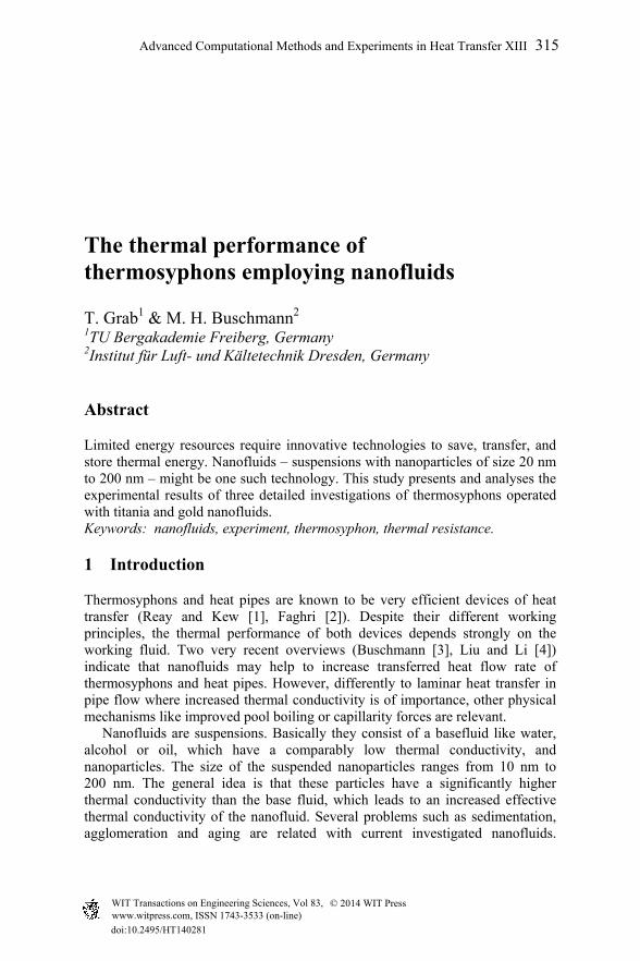
Moreover, modeling of these special liquids is complicated and still not completely understood (Feja and Buschmann [5]). Several physical mechanisms are discussed which could be relevant for an increase of the amount of transferred heat, i.e. a lowering of the thermal resistance [3, 4]. Due to the fact that nanofluids have higher thermal conductivity than classical working fluids, it is sometimes argued that this enhanced thermophysical property increases heat conduction within the working fluid. Keeping in mind that thermosyphons and heat pipes mostly run under pool boiling conditions where vapor bubbles stir the working fluid significantly, the heat conduction aspect seems to be rather negligible. Another idea is that nanoparticles bombard the vapor bubbles, which should lead to a higher bubble departure frequency. Again this argument seems implausible. Vapor bubbles have a size of several microns, which is several orders of magnitude larger than nanoparticles. In heat pipes nanoparticles may coat the wick and lead to an enhanced capillarity, which in turn transports more working fluid. But this is not the case for thermosyphons. Here it is rather likely that nanoparticles form a porous layer on the evaporator surface, which leads to an increased roughness. This roughness may provide a larger number of nucleation sites, which in turn increase bubble release frequency and lead to a higher amount of vapor produced. The scope of this study is the presentation and comparison of results obtained with three different closed two-phase thermosyphons employing water-based titania (TiO2) and gold (Au) nanofluids. In all three cases the thermosyphons are upright standing pipes consisting of evaporator, adiabatic region and condenser. However, all three thermosyphons are very different with respect to the design and size. A general sketch of a thermosyphon is shown in Fig. 1. The working
Figure 1: Schematically sketch of thermosyphon according to [3].
316 Advanced Computational Methods and Experiments in Heat Transfer XIII
fluid is located in the lower part of the device. The thermosyphon is evacuated so that in case the working fluid is heated, pool boiling takes place. Vapor rises upward and condenses on the inner side of the condenser. The condensate film runs down the inner wall of the thermosyphons and joins the working fluid again in the lower part of the device. The high efficiency of thermosyphons follows from the phase change being utilised.
2 Experiments
2.1 Test rigs
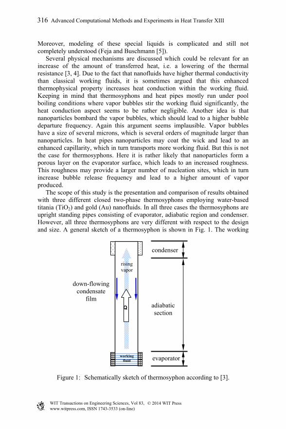
The three test rigs are shown in Fig. 2. The largest thermosyphons (no. 1) were built at TU Bergakademie Freiberg. The test rig indeed consists of four thermosyphons identical in construction. All four thermosyphons are 1440 mm long and have an inner diameter of 108 mm. The material of the pipes is stainless steel. The working fluid is heated with three cylindrical heater cartridges providing together up to 500 W. The condenser is cooled with cooling water with an inlet temperature of 21°C. Temperature is measured in the centre of the working fluid and at the inlet and outlet of the condenser cooling coil. From the latter, together with the measured cooling volumetric flow rate, the transferred amount of heat is calculated.
Figure 2: Thermosyphons employed for the study. Upper left photo shows large thermosyphons (no. 1) at TU Bergakademie Freiberg, upper right photo shows small thermosyphons (no. 3) without insulation at ILK Dresden, and at center is the large thermosyphon at ILK (no. 2).
Advanced Computational Methods and Experiments in Heat Transfer XIII 317
The second thermosyphon (no. 2) was built just recently at ILK. It consists of a 1800 mm long copper pipe with an inner diameter of 20 mm. Evaporator and condenser are identical in construction and formed as coil heat exchangers of 400 mm length at both ends of the thermosyphon. Coolant is again water which enters the evaporator in a temperature range between 40°C and 60°C. The third thermosyphon (no. 3) was built in 2013 at ILK and is much smaller than no. 1 and no. 2. The pipe consists of borosilicate glass. The glass allows observation of the working fluid after the experiment. During operation the thermosyphon is insulated as the two other devices to avoid heat losses. Heat is provided by a cylindrical heater at the lower end of the devices and ranges between 20 W and 60 W. A cooling coil is wrapped around the upper end of the glass cylinder forming the condenser. In all three cases deionised water is employed for reference measurements. Error of thermal resistance and other relevant parameters is calculated in any case based on Gaussian law of error propagation and indicated with error bars in the relevant figures.
2.2 Nanofluids
Two nanofluids with different nanoparticle concentrations are employed as working fluid. The first nanofluid is a suspension of TiO2-nanoparticles in water. It is employed in thermosyphon no. 1 and no 2. It is not employed in no. 3 simply due to the fact that this narrow thermosyphon cannot be cleaned easily. Nanoparticle concentration varies between 0.1 vol.% and 0.4 vol.%. All titania nanofluids are dilutions of AerodispW740X (EVONIK GmbH, Germany), which has a nanoparticle concentration of 12.6 vol.%. The mean hydrodynamical diameter of the agglomerates measured with a Zetasizer Nano ZS (Malvern Instruments GmbH, Germany) is about 85 nm. This is roughly twice the size of the primary nanoparticles specified by the manufacturer with 42 nm. While the titania nanofluid is obtained utilising a two-step procedure – dispersing dry nanoparticles in the basefluid – the gold nanofluid is produced employing a one-step laser ablations technology (Particular GmbH, Germany). For that purpose a gold target is placed in the basefluid water. A laser entering the reservoir via an optical system destroys the target and fabricates gold vapor which condenses to spherical gold nanoparticles. The technology is limited to small concentrations due to the fact that an increasing amount of nanoparticles reflects more and more of the laser beam so that the target cannot be reached if the suspension is too opaque. Therefore, the concentration of these nanofluids is, with 2.88 10-4 vol.%, comparably low. Two different sizes of gold nanoparticles – 16 nm and 66 nm – are investigated. Gold nanofluids are employed in all three thermosyphons. While all titania dilutions have a milky white colour, the two gold nanofluids appear bordeaux red when they are fresh and unused. Nanoparticle debris may coat any part of the inner surface of a thermosyphon. Such a coating would change local heat transfer conditions in an a priori unpredictable manner. If two nanofluids are employed in one thermosyphon
318 Advanced Computational Methods and Experiments in Heat Transfer XIII
without cleaning or even changing major parts of the device, the effects following from different nanoparticle debris would mix indistinguishably. Therefore, only one nanofluid is employed in one thermosyphon (no. 1 and no. 2) or the device is cleaned extremely carefully (no. 3).
3 Results
The general idea of employing nanofluids in thermosyphons and heat pipes is to increase the amount of transferred heat. Experimental procedure and data analysis have to follow this idea and to provide corresponding information and design rules. Therefore, a two step data analysis is employed. In the first part we calculate and present the thermal resistance of all three devices in dependence of the provided heat flow rate at the evaporator. The second part of the data analysis consists of a similarity analysis, which leads to a representation of the data in the form of non-dimensional parameters, namely Nusselt numbers, and non-dimensional temperature difference between evaporator and condenser. However, to get an insight into evaporation processes taking place in the evaporator region we start with an inspection of the evaporator surface immersed in the working fluid.
3.1 Evaporator surfaces
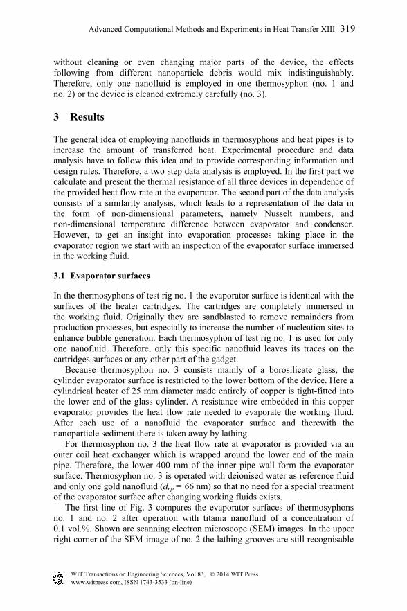
In the thermosyphons of test rig no. 1 the evaporator surface is identical with the surfaces of the heater cartridges. The cartridges are completely immersed in the working fluid. Originally they are sandblasted to remove remainders from production processes, but especially to increase the number of nucleation sites to enhance bubble generation. Each thermosyphon of test rig no. 1 is used for only one nanofluid. Therefore, only this specific nanofluid leaves its traces on the cartridges surfaces or any other part of the gadget. Because thermosyphon no. 3 consists mainly of a borosilicate glass, the cylinder evaporator surface is restricted to the lower bottom of the device. Here a cylindrical heater of 25 mm diameter made entirely of copper is tight-fitted into the lower end of the glass cylinder. A resistance wire embedded in this copper evaporator provides the heat flow rate needed to evaporate the working fluid. After each use of a nanofluid the evaporator surface and therewith the nanoparticle sediment there is taken away by lathing. For thermosyphon no. 3 the heat flow rate at evaporator is provided via an outer coil heat exchanger which is wrapped around the lower end of the main pipe. Therefore, the lower 400 mm of the inner pipe wall form the evaporator surface. Thermosyphon no. 3 is operated with deionised water as reference fluid and only one gold nanofluid (dnp = 66 nm) so that no need for a special treatment of the evaporator surface after changing working fluids exists. The first line of Fig. 3 compares the evaporator surfaces of thermosyphons no. 1 and no. 2 after operation with titania nanofluid of a concentration of 0.1 vol.%. Shown are scanning electron microscope (SEM) images. In the upper right corner of the SEM-image of no. 2 the lathing grooves are still recognisable
Advanced Computational Methods and Experiments in Heat Transfer XIII 319
(region marked with orange broken lines). Clearly the caking of nanoparticles is visible in both cases. Indeed, inspection with the naked eye reveals already that the complete evaporator surfaces are covered with milky white layers. The SEM images additionally indicate structures which are much larger than the original hydrodynamical diameter of the titania nanoparticles of 85 nm. In both cases nanoparticles have formed a massive porous layer which looks quite similar. The original surface of the heater cartridges from thermosyphon no. 1 is shown in Fig. 3c. The surface is characterised by the crater-shaped structures following from sandblasting. As for the lathed surface of the heater from thermosyphon no. 3, the original roughness is completely gone after employing the gold nanofluid (Fig. 3d). The gold nanoparticles obviously fill in the primary roughness of the crater-shaped pits. However, compared to the titania nanofluids, the layer formed by the gold nanofluid is much smoother.
Figure 3: SEM-images of evaporator surfaces. Top row shows no. 1 (left, 100-fold) and no. 2 (right, 39-fold) after use of TiO2-nanofluid of 0.1 vol.%. Second row compares no. 1 fresh (left) and after operation with gold nanofluid (right). The two lower SEM-images are both 100-fold enlarged.
3.2 Thermal resistance
Besides the absolute amount of transferred heat the thermal resistance is a characteristic parameter which speaks about improvement or deterioration of thermal performance of thermosyphons and related gadgets. Thermal resistance is defined as ratio of temperature difference between evaporator and condenser Tec to transferred heat qc.
320 Advanced Computational Methods and Experiments in Heat Transfer XIII
Fig. 4 presents the ratio of thermal resistance obtained for thermosyphons no. 1 and no. 2 when operated with nanofluid to thermal resistance when operated with deionised water. For all nanofluids a lowering of the thermal resistance is found when a low heat flow rate is provided at the evaporator. However, the lowering depends obviously on the material of the nanoparticles. The results also show that the concentration of the titania nanofluids is inconsequential (left plot of Fig. 4). For these nanofluids the improvement is restricted to specific heat between 10 kW/m² and maximal 30 kW/m². Surprisingly, we found that despite their much lower concentration the gold nanofluids perform better. Lowering of the thermal resistance up to a heat flow rate of 40 kW/m² is achieved (right plot of Fig. 4). Additionally, the lowering is more significant when gold nanofluids are employed. While titania nanofluids show an improvement of maximal 10%, the gold nanofluids can reach 20% at 10 kW/m².
Figure 4: Comparison of thermal resistances of thermosyphons operated with deionized water and operated with different nanofluids in dependence of specific heat flow rate provided at evaporator. Shown are results of thermosyphon no. 1.
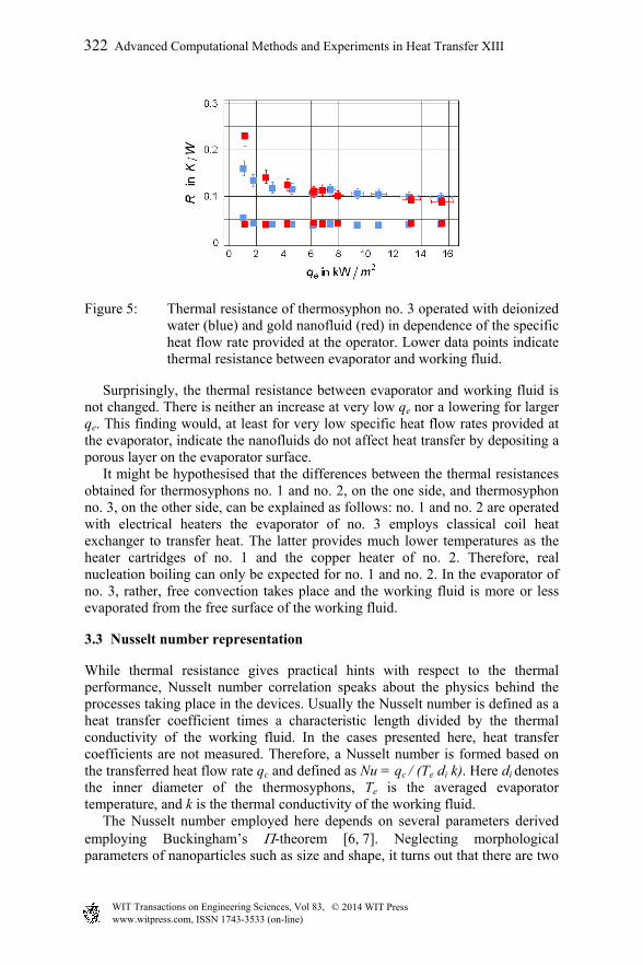
Fig. 5 shows the thermal resistance of thermosyphon no. 3. For this device it is not possible to calculate the ratio of thermal resistances as done for the two other gadgets. The reason is that the shown results are obtained by varying the inlet temperatures of the water flows running through evaporator and condenser. The consequence is that for identical inlet conditions due to the different operation regimes following from different working fluids (deionised water or nanofluid), the same heat flow rates are not extracted from the evaporator. However, Fig. 5 clearly reveals that for very low specific heat flow rates the thermal resistances is well above the results when the gold nanofluid is employed. This indicates a significant deterioration of the thermal performance of thermosyphon no. 3 when operated with nanofluid. The situation may improve if specific heat flow rate exceeds 12 kW/m2, where the total thermal resistance of thermosyphon no. 3 operated with gold nanofluid is slightly below the equivalent water values.
Advanced Computational Methods and Experiments in Heat Transfer XIII 321
Figure 5: Thermal resistance of thermosyphon no. 3 operated with deionized water (blue) and gold nanofluid (red) in dependence of the specific heat flow rate provided at the operator. Lower data points indicate thermal resistance between evaporator and working fluid.
Surprisingly, the thermal resistance between evaporator and working fluid is not changed. There is neither an increase at very low qe nor a lowering for larger qe. This finding would, at least for very low specific heat flow rates provided at the evaporator, indicate the nanofluids do not affect heat transfer by depositing a porous layer on the evaporator surface. It might be hypothesised that the differences between the thermal resistances obtained for thermosyphons no. 1 and no. 2, on the one side, and thermosyphon no. 3, on the other side, can be explained as follows: no. 1 and no. 2 are operated with electrical heaters the evaporator of no. 3 employs classical coil heat exchanger to transfer heat. The latter provides much lower temperatures as the heater cartridges of no. 1 and the copper heater of no. 2. Therefore, real nucleation boiling can only be expected for no. 1 and no. 2. In the evaporator of no. 3, rather, free convection takes place and the working fluid is more or less evaporated from the free surface of the working fluid.
3.3 Nusselt number representation
While thermal resistance gives practical hints with respect to the thermal performance, Nusselt number correlation speaks about the physics behind the processes taking place in the devices. Usually the Nusselt number is defined as a heat transfer coefficient times a characteristic length divided by the thermal conductivity of the working fluid. In the cases presented here, heat transfer coefficients are not measured. Therefore, a Nusselt number is formed based on the transferred heat flow rate qc and defined as Nu = qc / (Te di k). Here di denotes the inner diameter of the thermosyphons, Te is the averaged evaporator temperature, and k is the thermal conductivity of the working fluid. The Nusselt number employed here depends on several parameters derived employing Buckingham’s -theorem [6, 7]. Neglecting morphological parameters of nanoparticles such as size and shape, it turns out that there are two
322 Advanced Computational Methods and Experiments in Heat Transfer XIII
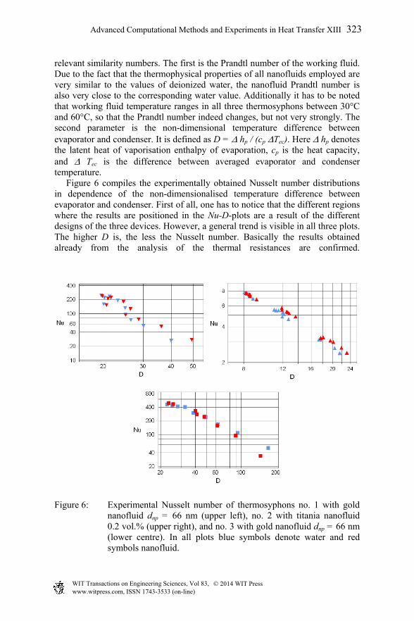
relevant similarity numbers. The first is the Prandtl number of the working fluid. Due to the fact that the thermophysical properties of all nanofluids employed are very similar to the values of deionized water, the nanofluid Prandtl number is also very close to the corresponding water value. Additionally it has to be noted that working fluid temperature ranges in all three thermosyphons between 30°C and 60°C, so that the Prandtl number indeed changes, but not very strongly. The second parameter is the non-dimensional temperature difference between evaporator and condenser. It is defined as D = hp / (cp Tec). Here hp denotes the latent heat of vaporisation enthalpy of evaporation, cp is the heat capacity, and Tec is the difference between averaged evaporator and condenser temperature. Figure 6 compiles the experimentally obtained Nusselt number distributions in dependence of the non-dimensionalised temperature difference between evaporator and condenser. First of all, one has to notice that the different regions where the results are positioned in the Nu-D-plots are a result of the different designs of the three devices. However, a general trend is visible in all three plots. The higher D is, the less the Nusselt number. Basically the results obtained already from the analysis of the thermal resistances are confirmed.
Figure 6: Experimental Nusselt number of thermosyphons no. 1 with gold nanofluid dnp = 66 nm (upper left), no. 2 with titania nanofluid 0.2 vol.% (upper right), and no. 3 with gold nanofluid dnp = 66 nm (lower centre). In all plots blue symbols denote water and red symbols nanofluid.
Advanced Computational Methods and Experiments in Heat Transfer XIII 323
Thermosyphons no. 1 and no. 2 perform better when operated with nanofluids as long as the temperature difference between evaporator and condenser is low. Note that D is the non-dimensional reciprocal of this temperature difference. Moreover, thermosyphon no. 3 indicates that if this temperature difference becomes very small, meaning D gets significantly larger, nanofluids act counter-productively. Of course these are only first insights that nanofluids may act in dependence of the evaporation regime. There might be a difference if the working fluid is evaporated via free convection at relatively low specific heat flow rates or if indeed pool boiling takes place at the evaporator surface.
4 Conclusion
Experimental results of three differently designed thermosyphons operated with deionised water and titania and gold nanofluids are presented. In some cases, but not in all, nanofluids improve thermal performance of these devices. Thermal resistance is lowered in dependence of the specific heat flow rate provided at the evaporator. Maximally, it can reach about 20%. However, further detailed research is needed to clarify the physical mechanisms behind the found improvement and why it is not obtained in all cases.
Acknowledgements
The present work was done under grant MF090026. The authors wish to thank S. Braune, J. Rehor and F. Smidt for supporting us with the experiments.
Taylor & Francis Group, 1995. [3] Buschmann, M.H., Nanofluids in thermosyphons and heat pipes: Overview
of recent experiments and modelling approaches, International Journal Thermal Sciences, 72, pp. 1–17, 2013.
[4] Liu, Z.H., Li, Y.Y., A new frontier of nanofluid research - Application of nanofluids in heat pipes, International Journal Heat Mass Transfer, 55, pp. 6786–6797, 2012.
[5] Feja, S., Buschmann, M.H., Nanofluids – Potentials and illusions, Split, Croatia, 12th Int. Conf. on Simulation and Experiments in Heat Transfer and their Applications, Split Croatia, 2012.
[6] Buschmann, M.H., Franzke, U., Improvement of thermosyphon perfor-mance by employing nanofluid, International Journal of Refrigeration, in press, 2014.
[7] Gersten, K., Herwig, H., Strömungsmechanik Fundamentals and Advances in Engineering Sciences. Vieweg, Wiesbaden, Germany, 1992.


![Nanofluids Review Paper [1]](https://static.documents.pub/doc/80x56/577cc7131a28aba7119fe55c/nanofluids-review-paper-1.jpg)


