Your We Votre reference ISBN: 978-0-494-63116-4 Our file Notre reference ISBN: 978-0-494-63116-4
NOTICE: AVIS:
The author has granted a nonexclusive license allowing Library and Archives Canada to reproduce, publish, archive, preserve, conserve, communicate to the public by telecommunication or on the Internet, loan, distribute and sell theses worldwide, for commercial or noncommercial purposes, in microform, paper, electronic and/or any other formats.
L'auteur a accorde une licence non exclusive permettant a la Bibliotheque et Archives Canada de reproduire, publier, archiver, sauvegarder, conserver, transmettre au public par telecommunication ou par Nnternet, preter, distribuer et vendre des theses partout dans le monde, a des fins commerciales ou autres, sur support microforme, papier, electronique et/ou autres formats.
The author retains copyright ownership and moral rights in this thesis. Neither the thesis nor substantial extracts from it may be printed or otherwise reproduced without the author's permission.
L'auteur conserve la propriete du droit d'auteur et des droits moraux qui protege cette these. Ni la these ni des extraits substantiels de celle-ci ne doivent etre imprimes ou autrement reproduits sans son autorisation.
In compliance with the Canadian Privacy Act some supporting forms may have been removed from this thesis.
Conformement a la loi canadienne sur la protection de la vie privee, quelques formulaires secondaires ont ete enleves de cette these.
While these forms may be included in the document page count, their removal does not represent any loss of content from the thesis.
Bien que ces formulaires aient inclus dans la pagination, il n'y aura aucun contenu manquant.
• + •
Canada
CONCORDIA UNIVERSITY
School of Graduate Studies
This is certify that the thesis prepared
By: HaiTao Yan
Entitled: The Thermo-Catalytic Cracking of Hydrocarbons: Hybrid Catalyst
Configuration and the Phenomena of Hydrogen Spill-over
and submitted in partial fulfillment of the requirements for the degree of
Master of Science (Chemistry)
Complies with the regulations of this University and meets the accepted standards with respect to originality and quality.
Signed by final examining committee:
Chair
Examiner
Examiner
Examiner
Supervisor
Approved by
Chair of Department or Graduate Program Director
20
Dean of Faculty
ABSTRACT
The Thermo-Catalytic Cracking of Hydrocarbons: Hybrid Catalyst Configuration and the
Phenomena of Hydrogen Spill-over
HaiTao Yan
Light olefins and diolefins such as ethylene, propylene, butenes and 1,3-butadiene
are considered as the backbone of the petrochemical industry. They are precursors of
numerous plastic materials, synthetic fibers, and rubbers. In recent years, the thermo
catalytic cracking (TCC) process has been developed in our lab with the objective to
selectively produce light olefins, particularly ethylene and propylene, from liquid
hydrocarbon feedstocks such as petroleum naphtha and gas oils. With the continuous
decline of conventional oil reserves, heavy petroleum feedstocks become essential
alternatives for commercial petroleum products. However, the preliminary catalytic
results in the TCC of heavy feedstock have indicated insufficient on-stream long-term
stability and a high selectivity to polyaromatic hydrocarbons, which are usually
considered as precursors for coke.
In this dissertation, hybrid catalysts have been developed and studied with the goal
of resolving the problems of stability of catalyst activity and selectivity. Several active
metal species (such as Ni, Re, Ru) have been loaded on the co-catalyst component
surface. These metal species are able to produce very active hydrogen species, in virtue
of its steam-reforming activity, and to spill them over to the acidic sites of the main
catalyst component. These hydrogen species, once transferred (or "spilt over") onto the
iii
surface of the main cracking catalyst component, might interact with the reaction
intermediate being adsorbed on the acidic sites. This resulted in a decreased formation of
coke precursors, and consequently, catalyst deactivation was significantly retarded. The
results obtained from cracking tests on both petroleum feedstocks and model molecules
indicated that the spilt-over hydrogen species had significant effects on heavy
hydrocarbon feedstocks, such as vacuum gas oil, and they could affect the reaction
intermediates only when the latter were formed on the external surface of microporous
ZSM-5 zeolite particles. Moreover, data of the most recent work show that it is necessary
to choose the ZSM-5 zeolite (that is the cracking component of the hybrid catalyst) that
has a high density of acid sites; however, its acid strength should be relatively mild in
order to achieve a high total conversion and a high propylene/ethylene product ratio.
These mild acid sites also lead to lower coke deposition and a lighter nature of coke thus
improving the cleaning action of the hydrogen spilt-over species.
iv
PROFESSIONAL ACKNOWLEDGMENTS
First and foremost, I would like to express my extreme gratitude to my supervisor
Prof. Raymond Le Van Mao for giving me the opportunity to work in his lab over the
past 3 years. I would like to thank you for introducing me to the world of catalysis,
petroleum chemistry and zeolites. I also want to thank you for your guidance,
encouragement, kindness, and patience during my time at Concordia University. Without
your valuable insight and input, as well as your entensive expertise, this work would not
have been possible or might not have ever come to fruition.
I cannot fail to mention my thesis committee members, Prof. Louis A. Cuccia and
Prof. Xavier Ottenwaelder. I would like to express my thanks and appreciation for their
helpful suggestions, encouragement and support throughout the course of this degree.
I would like to sincerely thank the current and past Industrial Catalysis Group: Dr.
Ngoc Thanh Vu, Lin Lu, and Dr. Nabil Al-Yassir. Thank you for your support, helpful
advices.
I would like to express my sincere appreciation to the Science Technical Center:
Mr. Richard Allix, Mr. Aldo Dissegna, Mr. Gheorghe Dan Duru, Mr. Chris Kowalewski,
and Mr. Robert Pisarsky. I always had a tremendous respect for your endless support, and
my words cannot entirely express my sincere gratitude.
v
PERSONAL ACKNOWLEDGMENTS
Needless to say, this entire M.Sc. dissertation would be at most a dream if there
were not my mother Hua Mei. I do not know how to start this, but I do know that no
matter how much I say, or how long it will take me to finish it, my words will not be
enough or definitely will run out before I adequately express my deep gratitude and
appreciation to my mother. You have supported me in many, many ways and this M.Sc.
is as much as yours as it is mine. Your countless emotional and moral support, endless
love, and unconditional sacrifice are the reasons why I make it to this point in my life.
Your encouragement meant the whole to me. You have waited so long for this moment to
come true; I am glad that your waiting has finally been rewarded.
vi
"No matter who wrote it, there's nothing we can't make intelligible."
{Pinball, 1973/Murakami Haruki}
"The introduction to Bonus Light, that exegesis of pinball, has this to say:
There is precious little you can gain from a pinball machine. Only some lights that
convert to a score count. On the other hand, there is a great deal to lose. All the coppers
you'd ever need to erect statues of every president in history (provided, of course, you
thought well enough to erect a statue of Richard M. Nixon), not to mention a lot of
valuable and nonreturnable time.
While you're playing yourself out in lonesome dissipation in front of a pinball
machine, someone else might be reading through Proust. Still another might be engaged
in heavy petting with a girlfriend at a drive-in theater showing of Paths of Courage. The
one could well become a writer, witness to the age; the others, a happily married couple.
Pinball machines, however, won't lead you anywhere. Just the replay light.
Replay, replay, replay .... So persistently you'd swear a game of pinball aspired to
perpetuity.
We ourselves will never know much of perpetuity. But we can get a faint inkling
of what it's like.
The object of pinball lies not in self-expression, but in self-revolt. Not in the
expansion of the ego, but in its compression. Not in extractive analysis, but in inclusive
subsumption.
So if it's self-expression or ego expansion or analysis you're after, you'll only be
subjected to the merciless retaliation of the tilt lamps.
Have a good game"
{Pinball, 1973/Murakami Haruki}
vii
%Ss W- ifZ7&&6r-7?jS,
viii
TABLE OF CONTENTS
LIST OF FIGURES xiii
LIST OF SCHEMES xvi
LIST OF TABLES xvii
CONTRIBUTIONS of AUTHORS xviii
Chapter I 1
GENERAL INTRODUCTION l
1.1. PREAMBLE 2
1.2. Light Olefins 3
1.2.1. Light Olefins as Precursors in Petrochemical Industry 3
1.2.2. Ethylene .' 5
1.2.3. Propylene 6
1.3. Light Olefins Production 8
1.3.1. Main Industrial Technologies for Light Olefins Production 8
1.3.2. Thermal (Steam) Cracking (SC) 9
1.3.3. Catalytic Cracking 11
1.3.4. Challenges in the Light Olefins Industry 17
1.4. Newly Developed Thermo Catalytic Cracking (TCC) Process 19
1.4.1. Overview oftheTCC Process 19
1.4.2. The Hybrid Catalyst Used in the TCC Process 20
1.4.3. The Hydrogen Spillover Phenomenon 21
1.5. Principles of Catalyst Characterization 23
1.5.1. Brunauer Emmet and Teller (BET) Technique 23
ix
1.5.2. Thermogravimetric and Differential Thermal Analyses (DTA/TGA) 25
1.5.3. Temperature Programmed Desorption of Ammonia (TPD-NH3) and Adsorption/Desorption of Pyridine 26
1.6. OUTLINE 27
Chapter I I 31
Effect of the Spilt-over Hydrogen Species on the Product Yields of the Hybrid Catalysts Used in the Thermocatalytic Cracking (TCC) Process for the Production of Light Olefins .31
2.1. INTRODUCTION 32
2.2. EXPERIMENTAL 33
2.2.1. Catalyst Preparation 33
2.2.2. Catalyst Characterization 36
2.2.3. Characterization of the Feeds (Hydrocarbon Feedstocks) 37
2.2.4. Experimental Setup and Testing Procedure 38
2.3. RESULTS AND DISCUSSION 42
2.3.1. Effect of the Hydrogen Spilt-Over Species on the Product Yields 42
2.3.2. Coke and Its "Advanced" Precursors 51
2.3.3. Effect of the Cracking Component (Main Catalyst Component) on the Product Propylene/Ethylene Ratio 52
2.4. CONCLUSION 56
2.5. AUTHOR'S NOTES AND SIGNIFICANCE OF PAPER TO THESIS 56
Chapter I I I 58
The Thermo-Catalytic Cracking of Hydrocarbons: Effect of Polymethylbenzenes Added to rc-Hexane Feed on the Reactivity of ZSM-5 Zeolite Containing Hybrid Catalyst 58
X
3.1. INTRODUCTION 59
3.2. EXPERIMENTAL 60
3.2.1. Catalyst Preparation 60
3.2.2. Catalyst Characterization 62
3.2.3. Experimental Set-up and Testing Procedure 62
3.3. RESULTS AND DISCUSSION 63
3.3.1. Tests with Pentamethyl Benzene (PMB) Added to n-Hexane Feed 65
3.3.2. Tests with 1,2,4-Trimethylbenzene (TMB) Added to «-Hexane Feed 68
3.4. CONCLUSIONS 72
3.5. AUTHOR'S NOTES AND SIGNIFICANCE OF PAPER TO THESIS 74
Chapter IV 75
Hybrid Catalysts Used in the Thermo-Catalytic Cracking Process (TCC): Influence of the Pore Characteristics and the Acidity Properties of the ZSM-5 Zeolite-Based Component on the Overall Catalytic Performance 75
4.1. INTRODUCTION 76
4.2. EXPERIMENTAL 78
4.2.1. Catalyst Preparation 78
4.2.2. Catalyst Characterization 79
4.2.3. Experimental Set-up and Testing Procedure 81
4.3. RESULTS AND DISCUSSION 82
4.3.1. Main Physico-Chemical Properties of the Hybrid Catalyst Components 82
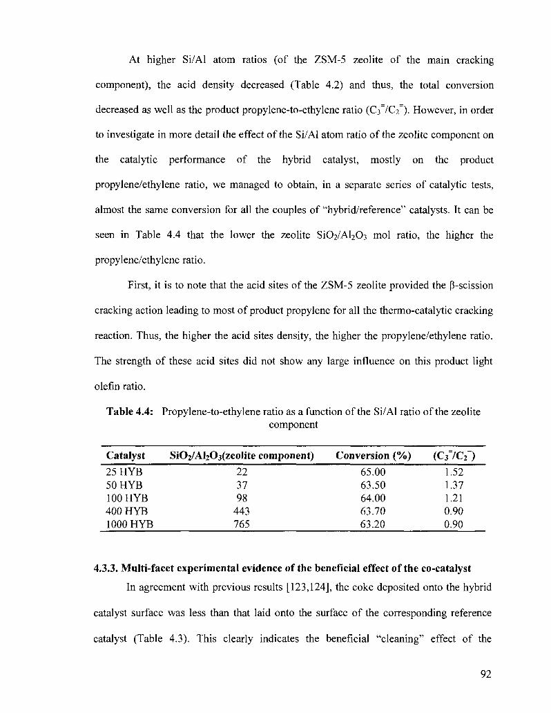
4.3.2. Catalytic Performance of Various Hybrid Catalysts, Related to the Si02/Al203 mol Ratio of Their Zeolite Components 89
xi
4.3.3. Multi-facet Experimental Evidence of the Beneficial Effect of the Co-catalyst... 92
4.3.4. Acceleration of the Coke Depositio by the "Contamination" Method 93
4.4. CONCLUSION 98
4.5. AUTHOR'S NOTES AND SIGNIFICANCE OF PAPER TO THESIS 100
Chapter V 101
General Conclusion, Ongoing and Future Work 101
5.1. GENERAL CONCLUSION 102
5.2. ONGOING AND FUTURE WORK 104
Chapter VI 106
REFERENCES 106
xii
LIST OF FIGURES
Figure 1.1 World ethylene end use, 2000 4
Figure 1.2 World propylene end use 5
Figure 1.3 Detailed schematic of a fluid catalytic cracking reactor 12
Figure 1.4 Propylene demand 18
Figure 1.5 Regional polypropylene demand 18
Figure 1.6 Concept of pore continuum in hybrid catalysts 21
Figure 1.7 Concept of hydrogen spillover phenomenon 22
Figure 2.1 On-stream behavior of hybrid catalyst HYB-l(l) and reference 42 catalyst REF-1
Figure 2.2 Assumed intervention level (IL) of the hydrogen spilt-over 50 species (being produced in situ on the co-catalyst surface) on the reaction intermediates at the cracking sites
Figure 2.3 FT-IR spectra of adsorbed pyridine of the main components 54 (MCC-1 (spectrum C) and MCC-2 (spectrum D)) and their corresponding "active" supports (AAS (spectrum A) and ZSM-5 zeolite (spectrum B))
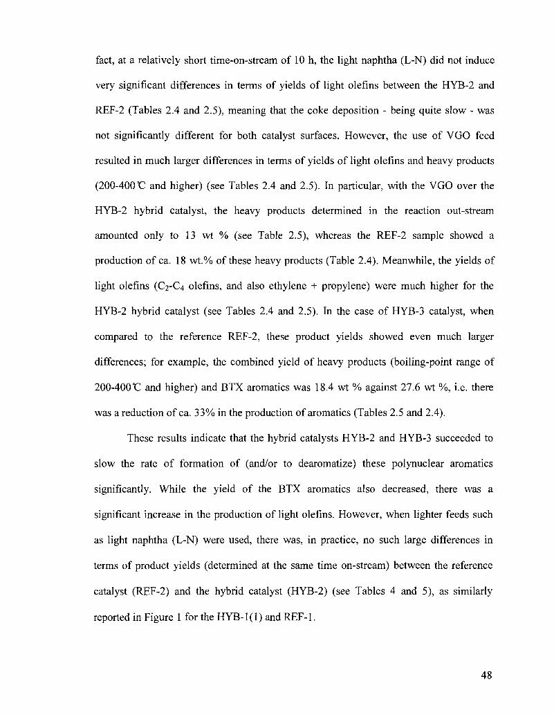
Figure 2.4 Acid strength profile obtained using the NH3-TPD/ISE method: 55 (A) H-ZSM5, (B) MCC-2, and (C) MCC-1. (A)) d[NH4]/dt (given in units of mmol g"loC"')
Figure 3.1 Total conversion (wt%) versus concentration (wt%) of PMB in 65 hexane
Figure 3.2 Product yield (wt%) in Ci-C4 hydrocarbons versus concentration 66 (wt%) of PMB in hexane
Figure 3.3 Product yield (wt%) in heavy hydrocarbons versus concentration 66 (wt%) of PMB in hexane
Figure 3.4 Coke deposition (wt%) versus concentration (wt%) of PMB in 67
xin
hexane
Figure 3.5 Combustion temperature of coke (T in°C) versus concentration 68 (wt%) of PMB in hexane
Figure 3.6 Total Conversion (wt%) versus concentration (wt%) of TMB in hexane
Figure 3.7 C1-C4 product yield (wt%) versus concentration (wt%) of TMB in hexane
Figure 3.8 Heavy product yield (wt%) versus concentration (wt%) of TMB in hexane
Figure 3.10 Combustion temperature of coke (T in°C) versus concentration (wt%) of TMB in hexane
Figure 4.3 FT-IR spectra of pyridine adsorbed onto the (100H HYB (up) and 1000H HYB (bottom)) hybrid catalyst (recorded at various temperatures)
68
71
71
Figure 3.9 Amount of coke deposited (wt%) versus concentration (wt%) of __ TMB in hexane
72
Figure 4.1 FT-IR spectra of pyridine adsorbed onto various hybrid catalysts „„ (recorded at 100 °C)
Figure 4.2 FT-IR spectra of pyridine adsorbed onto (25H HYB) hybrid catalyst (recorded at various temperatures)
88
Figure 4.4 Effect of the 1,3,5-TMB "contamination" on the total conversion Qt. of the (25H) hybrid and that of the (25H) reference catalysts
Figure 4.5 Effect of the 1,3,5-TMB contamination of the selectivity in C2-C4 „_ olefins of the (25H) hybrid and that of the (25H) reference catalysts
Figure 4.6 Coke deposition onto the (25H) hybrid and reference catalysts in Q , the presence of 1,3,5-TMB contaminant
xiv
Figure 4.7 Effect of the massive contamination by 1,2,4-TMB on the total 97 conversion
Figure 4.8 Effect of the massive contamination by 1,2,4-TMB on the 97 selectivity in C2-C4 olefins
Figure 4.9 Effect of the massive contamination by 1,2,4-TMB on the coke 98 deposition
Figure 4.10 Effect of the massive contamination by 1,2,4-TMB on the nature 98 of the coke deposited
xv
LIST OF SCHEMES
Scheme 1.1 Major chemicals based on ethylene
Scheme 1.2 Major chemicals based on propylene
Scheme 1.3 The main important current sources of light olefins
Scheme 1.4 Steam cracking. Reaction mechanism
Scheme 1.5 Individual steps of catalytic cracking reactions
Scheme 1.6 Schematic representation of TCC multi-zone reactor configuration
LIST OF TABLES
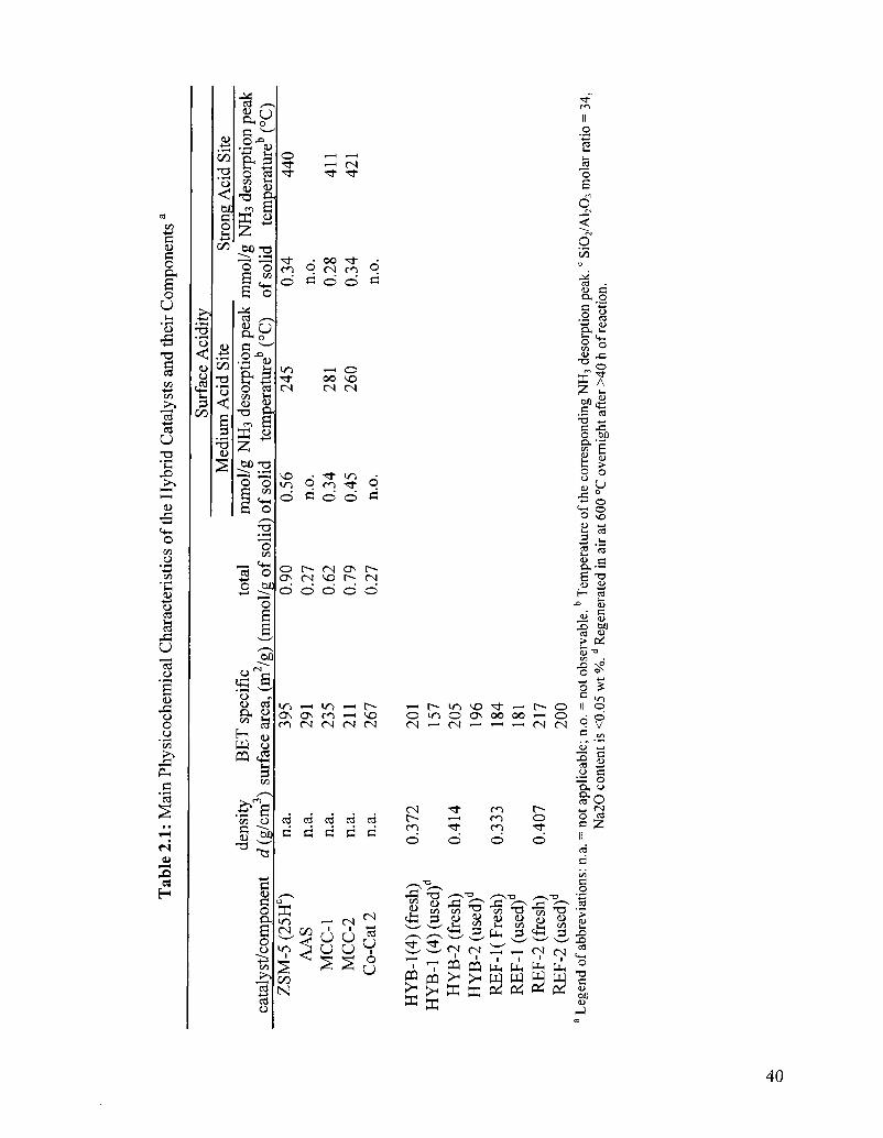
Table 2.1 Main physicochemical characteristics of the hybrid catalysts 40 and their components3
Table 2.2 Characteristics of the hydrocarbon feedstocks tested3 41
Table 2.3 Effect of the co-catalyst on the prodcuct selectivity of the 44 resulting hybrid catalyst (series HYB 1 )a
Table 2.4 Performance of the Reference Catalyst REF-2, using various 46 feedstocks3
Table 2.5 Performance of the Reference Catalyst REF-2, using various 47 feedstocks3
Table 2.6 Tabulated results for the DTA/TGA analysis of reference (REF- 50 2) and hybrid (HYB-2) catalysts in various environments3
Table 2.7 Performance of hybrid catalyst HYB-1(4) and reference catalyst 53 REF-13
Table 3.1 Pore Characteristics of the ZSM-5 zeolite, the Y-AA, the Z- 64 HYB catalyst and Z-REF
Table 4.1 BET surface areas of various catalyst components or catalysts 84 used in this work, SAR = external/internal surface area ratio
Table 4.2 Surface acidity properties of parent ZSM-5 zeolites and 86 corresponding catalysts. The density of acid sites was obtained by back-titration method and the distribution of acid site strength (zeolites) was determinded by ISE methos.
Table 4.3 Catalytic performances of hybrid catalysts and their 91 corresponding references
Table 4.4 Propylene-to-ethylene ratio as a function of the SiC^/AbC^ mol 92 ratio of the zeolite component
Table 4.5 Co-catalyst content versus the coke deposition 93
xvii
CONTRIBUTIONS OF AUTHORS
The following summarizes the contributions of each the authors cited in this dissertation.
CHAPTER II: "Effect of the spilt-over hydrogen species on the product yields of the hybrid catalysts used in the Thermo-Catalytic Cracking (TCC) process for the production of light olefins"
R. Le Van Mao: project supervisor and manuscript preparation
N. T. Vu: experimental work
N. Al-Yassir: experimental work
H. T. Yan: experimental work
CHAPTER III: "The Thermo-catalytic Cracking of hydrocarbons: Effect of polymethylbenzenes added to the n-hexane feed on the reactivity of ZSM-5 zeolite containing hybrid catalyst"
H. T. Yan: experimental work and manuscript preparation
R. Le Van Mao: project supervisor and manuscript preparation
CHAPTER IV: "Hybrid catalysts used in the Thermo-Catalytic Cracking process (TCC): influence of the pore characteristics and the acidity properties of the ZSM-5 zeolite-based component on the overall catalytic performance"
H. T. Yan: experimental work and manuscript preparation
R. Le Van Mao: project supervisor and manuscript preparation
xviii
CHAPTER I
GENERAL INTRODUCTION
1.1. PREAMBLE
Light olefins and diolefins such as ethylene, propylene, butenes and butadienes
are the key building blocks for the production of important petrochemicals. They are the
precursors of numerous plastic materials, synthetic fibers and rubbers, so that they are
considered as the backbone of the petrochemical industry. These basic chemicals are
currently manufactured mainly by Steam Cracking (SC) and recently Fluid Catalytic
Cracking (FCC) using ZSM-5 zeolite containing catalysts. Other technologies such as
Deep Catalytic Cracking, Catalytic Dehydrogenation, Methanol to Olefins and Olefin
Metathesis have also been studied and developed; however, these processes only cover a
small part of the light olefins demand. As the rapid growth of the world demand
(particularly for propylene that is produced as a co-product by conventional light olefins
technologies) and the increasingly stringent environmental regulations requiring lower
greenhouse gases emissions, it is imperative to develop a new process with improved
production of light olefins.
The Thermo Catalytic Cracking (TCC) process has been developed and
extensively studied since 1998, that can be regarded as a promising alternative process
for light olefins production. The preliminary results show that the TCC offers several
advantages when compared to the conventional SC: it gives higher combined yields of
ethylene and propylene from the low-commercially valued heavy products, it results in
lower emission of greenhouse gases, and it consumes less energy. The TCC process
combines the effects of thermal and catalytic cracking reactions. Most catalysts used are
in the hybrid configuration, which contain two components: a main component having
cracking properties owing to acidic surface sites and a co-catalyst that is capable of
2
affecting the product selectivity of the former components. These two components are
firmly bound to each other within an inert binder, so that a "pore continuum" is
developed whose effect is to ease the transfer of the reaction intermediates within the
catalyst network.
Various aspects of the catalytic configuration and the reaction parameters need to
be balanced in order to further improve the TCC. For example, the hydrogen spillover
(HSO) effect can be introduced to improve the catalyst stability and reactivity. A deeper
understanding of the synergy between the different components of the hybrid catalyst
structure and the influence of its physical and chemical factors can help improve the TCC
efficiency significantly.
1.2. Light Olefins
1.2.1. Light Olefins as Precursors in Petrochemical Industry
In organic chemistry, an olefin is defined as an unsaturated chemical compound
containing at least one carbon-to-carbon double bond. [1] The simplest acyclic alkenes,
with only one double bond and no other functional groups, form a homologous series of
hydrocarbons with the general formula CnH2n. [2] In comparison with paraffinic
hydrocarbons, olefins are characterized by their higher reactivities. They can easily react
with inexpensive reagents such as water, oxygen, hydrochloric acid, and chlorine to form
valuable chemicals. In addition, polymers such as polyethylene and polypropylene can be
produced by polymerization. [3] Since light olefins are the precursors of numerous plastic
materials, synthetic fibers, and rubbers, they have been recognized as key building blocks
of the petrochemical industry. The market demand for ethylene and propylene in the year
2005 was 107 and 67.1 million metric tons (Mt), respectively. Global ethylene demand
3
growth is about 4.5-5% per year; global propylene demand growth typically averages
over around 5% per year. [4] The demand for ethylene and propylene is projected to
increase to about 140 and 90 million Mt by 2010, respectively. [5] The significance of
light olefins industry stems from the great demands for polyolefins particularly
polyethylene and polypropylene. [6] Fig. 1.1 and Fig. 1.2 show the main end uses of
ethylene [7] and propylene (1970 and 2004) [8]. The share of polyolefins of the total
polymer market increased approximately from 30% to 60% since 1970, and this demand
will continue to grow, because of the constant growing demands from developing
countries like China and India, where only few materials can match their versatility and
As shown in Fig. 1.5 [8], Asia is going to be the dominant region with respect to the high
world propylene demand in the near future. However, with the current technology,
propylene is only produced as a by-product or at best a co-product. About 70% of
worldwide production for propylene comes from steam cracking as a co-product to
ethylene, 28% from fluid catalytic cracking as a co-product to gasoline and the remaining
18
2% from on-purpose processes such as catalytic propane dehydrogenation, metathesis
and other. [37] As a result of continuous rapid growth in the demand for propylene, a
great deal of pressure will be added on conventional olefin technologies. [6]
In addition to the rapid growth in the demand for propylene, the energy
consumption is another significant roadblock in the light olefins industry. The current
steam cracking process consumes as much as 40% of the energy used by the entire
petrochemical industry due to the high operation temperature. [38]
Also, global environmental issues have stimulated the development that
minimizes greenhouse gases (GHG) emissions. [38] Greenhouses gases such as CH4 and
CO2 are produced during the run-regeneration cycle. For example, total greenhouse gas
emissions in Canada in 2006 were 721 mega tonnes of carbon dioxide equivalent (Mt of
CO2 eq). [39] The emission from fossil fuel industries was 43.1 mega tonnes. Thus, more
strict environmental regulations require low greenhouse gases emission also put a strain
on the conventional olefins technologies. [6]
1.4 Newly Developed Thermo Catalytic Cracking (TCC) Process
1.4.1. Overview of the TCC process
The thermo catalytic cracking (TCC) has been developed and extensively studied
since 1998 with the objective to selectively produce light olefins, particularly ethylene
and propylene in quite equal proportions, from liquid hydrocarbon feedstocks (i.e.
petroleum naphthas and gas oils). [40-45] This process has been recognized as a
promising alternative route for light olefins. [6] The TCC process combines the (mild)
thermal cracking with the effect of a moderately acidic catalyst. By doing this, high
yields of ethylene and propylene (and other light olefins) can be produced while
19
operating at a temperature much lower than those used for the steam cracking process.
Also, this process shows a significantly lower emission of greenhouse gases, compared to
the conventional steam cracking. [43]
There are two versions of the TCC process: one-zone and multi-zone reactors, on
a one-zone reactor, the catalysts need to work under steam atmosphere and at quite high
temperature. As show in scheme 1.6, the multi-zone reactor configuration comprises a
precatalytic zone (quartz beads) and a catalyst bed (catalyst extrudates). [6]
Steam r.rackinc) zone ( I J ca ta lys t bed Zone Cl IO
gas- sampler wi th bypass tube -..
Flow meter
Feeds cocks
preheater
to fume hood
QC/FI.D/MS arieily^Hr
Cooling Zone (IX') cryogenic f rac t iona to r
Scheme 1.6: Schematic representation of TCC multi-zone reactor configuration [6]
1.4.2. The Hybrid Catalyst Used in the TCC process
Most catalysts used in the TCC process are in hybrid configuration. They are
constituted of two porous components. The main component has active sites having
cracking properties (acid sites). The co-catalyst has an active surface that can affect the
product selectivity of the former (cracking) sites. For the most recent version of the TCC
catalysts, the role of the main component is to crack large hydrocarbon molecules over
the active sites provided by the (Mo-P) species while the resulting smaller molecules are
subsequently cracked over the acid sites from the surface of a zeolite (i.e ZSM-5). [42]
The co-catalyst contains active metal species (Ni, Re, Ru) that are dispersed on a
20
thermally and hydrothermally stable support. [42, 43, 46] Finally, these two components
are bound to each other by bentonite clay, which is an inert inorganic binder. The "ideally
sparse particles configuration" in the hybrid catalyst ensures an easy two-way diffusion
of reaction intermediates within the catalyst network, in virtue of the "pore continuum"
effect (Fig. 1.6). [47-49]
Mesoporous
• • • •
^F7. Microporous
Fig. 1.6: Concept of pore continuum in hybrid catalysts
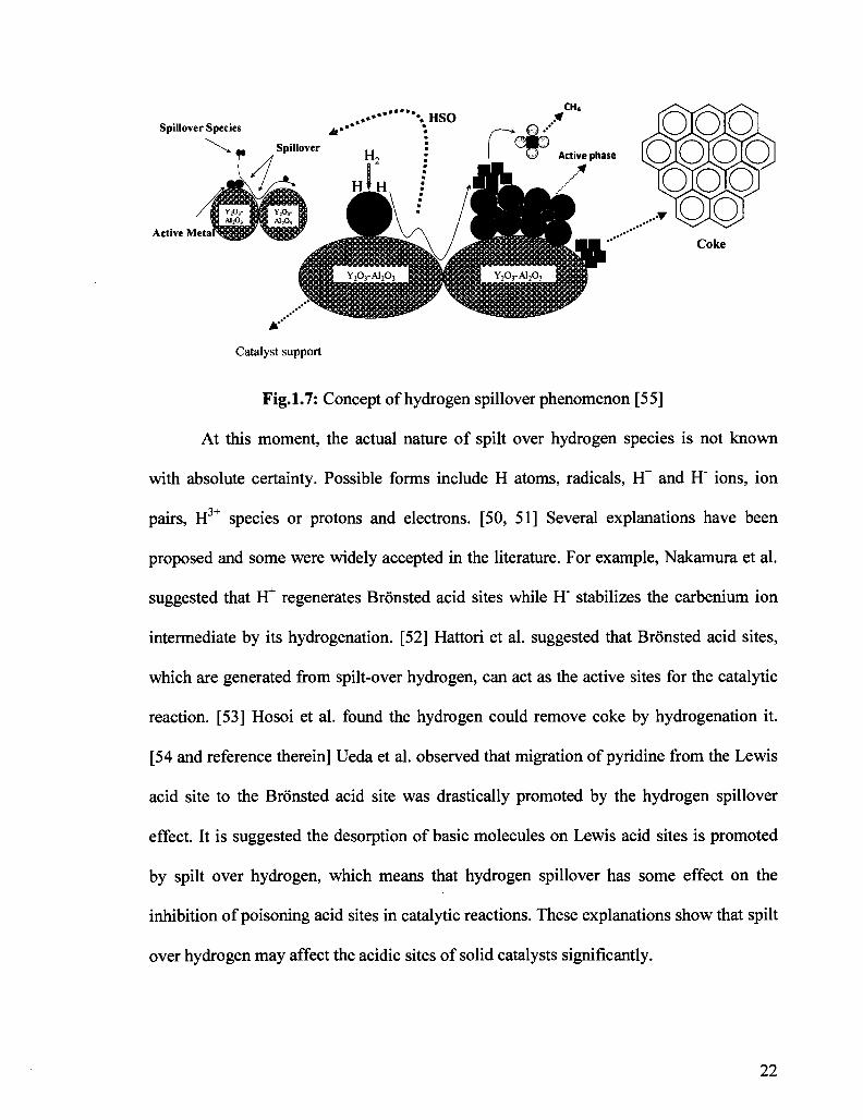
1.4.3. The Hydrogen Spillover Phenomenon
Particularly in the present study, the role that the co-catalyst is expected to play is
to promote the hydrocarbon steam-reforming. Then, some hydrogen species can be
produced and then spilt over onto the surface of the main acidic component. These
hydrogen spilt-over (HSO) species may interact with the intermediates of the cracking
reaction on the surface of the main component. Thus, the formation of coke precursors
can be retarded, so that the run length can be improved(Fig.l .7).
21
Fig.1.7: Concept of hydrogen spillover phenomenon [55]
At this moment, the actual nature of spilt over hydrogen species is not known
with absolute certainty. Possible forms include H atoms, radicals, H+ and H" ions, ion
pairs, H3+ species or protons and electrons. [50, 51] Several explanations have been
proposed and some were widely accepted in the literature. For example, Nakamura et al.
suggested that Yt regenerates Bronsted acid sites while H' stabilizes the carbenium ion
intermediate by its hydrogenation. [52] Hattori et al. suggested that Bronsted acid sites,
which are generated from spilt-over hydrogen, can act as the active sites for the catalytic
reaction. [53] Hosoi et al. found the hydrogen could remove coke by hydrogenation it.
[54 and reference therein] Ueda et al. observed that migration of pyridine from the Lewis
acid site to the Bronsted acid site was drastically promoted by the hydrogen spillover
effect. It is suggested the desorption of basic molecules on Lewis acid sites is promoted
by spilt over hydrogen, which means that hydrogen spillover has some effect on the
inhibition of poisoning acid sites in catalytic reactions. These explanations show that spilt
over hydrogen may affect the acidic sites of solid catalysts significantly.
22
1.5. Principles of Catalyst Characterization
1.5.1. Brunauer Emmet and Teller (BET) Technique
BET technique can be used to determine certain textural properties of porous
solids, for example the specific surface area, the pore volume, the average pore diameter,
the pore shape, the pore size distribution, and the shape of the nanometric cavities and
pore openings. [56]
The specific area is defined as the measurement of the accessible surface area per
unit mass of solid (adsorbent); this surface S is the sum of the internal pore surface area
and of the external boundary surface area,
c — A Na*Vm 771 i7
vm
where S is the specific surface area, Na is the Avogadro constant, Vm is the molar volume
of the adsorbate, Am is the part of surface occupied by one molecule of adsorbate in a
close layer (for example, for nitrogen, Am is equal to 16.2*10"20m ), Vm is the monolayer
capacity of the unit mass of adsorbent (the volume of adsorbate just sufficient to cover
the surface developed by the unit mass of adsorbent) and can be determined by BET
method.
In 1938, Brunauer, Emmett and Teller (BET) proposed a model for physical
adsorption of gas molecules on a solid surface and Vm can be estimated by the BET
equation,
x _ 1 C-l Va(l-x)~V^C + ~V^X
where Va is the adsorbed volume of the adsorbate per unit mass of adsorbent, Vm is the
monolayer capacity of the unit mass of solid, x is the relative pressure p/po, C is a
23
constant that is dependent on the adsorbent-adsorbate interaction. [56] It behaves as a
straight-line in the form of y = ax + b for x varying from 0.05 to 0.35. Subsequently, Vm
and C can be derived from the slope and intercept of the line on the graph. To apply the
equation, they assumed the following facts: (1) a multilayer adsorption even at very low
pressure; (2) the adsorption occurring on well defined sites and all the sites have the same
energy, each of them can only accommodate one adsorbate molecule; (3) adsorption-
desorption equilibrium is supposed to be effective between molecules reaching and
leaving the solid surface.
The specific pore volume is defined as the accessible pore void space in the
particles per unit mass of solid.
The cumulative specific surface or pore volume (Scum and Vcum) are the sum on k
of
^cum ~ 2J ^k ''cum ~ /Li^k
where Sk and Vk are respectively the specific surface area and the volume of the pores of
radius rk for the kth interval: Sk = 2Vk/rk-
The pore size distribution is the distribution of the pore volume versus the pore
size.
The average pore size is obtained by the equation: raverage = 2VP/S, where Vp is the
pore volume, and S is the total surface area. The pores are classified into macropores
(with size larger than 50nm), or mesopores (with size in the range from 2nm to 50 nm) or
micropores (with size smaller than 2nm).
For the BET method, the most popular adsorbates are nitrogen and argon.
Usually, nitrogen is preferred due to its availability and low cost. In this work, all the
24
measurements of solids and catalysts were carried out on the basis of nitrogen adsorption
isotherms. The textural studies were carried out with a Micromeretics ASAP 2000 Model
system. The specific surface area was measured by BET method (i.e. BET plot at relative
pressure between 0.05 and 0.35). Microporous volume and surface area were measured
by t-plot method, which is a linear curve of the adsorbed volume against t (the statistical
thickness t of the adsorbed layer) in the range of 0.35 and 0.5 nm. Its slope is directly
proportional to the surface area and its positive intercept by extrapolating the line to t = 0
corresponds to the adsorbed volume of micro pores. The reference isotherm used to
determine the dependence oft vs. p/po is derived from the Harkins-Jura equation:
110
t = (13.99 / (0.034 - log (p/po)) • Mesoporous volume and mesopore size distribution
were determined by the method of Barrer, Joyner and Halenda (BJH). In mesopores
regions, the adsorption capillary condensation takes place when p/po is greater than 0.4
based on Kelvin equation. The physical volume of pores and the average pore size can be
calculated from the adsorbed volume and the assumed pore geometry. The pore size
distribution was investigated by plotting the differential pore volume F = dV/dlogD as a
function of the pore diameter D (desorption phase, V and D in cm3 and nm, respectively).
Macropore volume was the difference between the total volume of uptake and the sum of
microporous and mesoporous volume. [57]
1.5.2. Thermogravimetric and Differential Thermal Analyses (DTA/TGA)
In the present work DTA/TGA techniques were carried out on a PL Thermal
Sciences, STA-1500 Model apparatus to investigate the amount and the nature of coke
deposited on surface of the catalysts used in the on-stream tests for the cracking of
hydrocarbons.
25
TGA is a technique in which the variation of the mass of a substance is measured
as the temperature of the substance is varied. Changes in the mass are caused by
decomposition or oxidation in the air of the substance. DTA is a technique which detects
the temperature changes between the sample and an inert reference material during a
programmed change of temperature, involving an exchange of energy (AH ^ 0), for
example a chemical reaction or a first order phase transition. The peaks on the DTA
curve show either exothermic or endothermic process which takes place in the sample
during the temperature programmed heating. Combined with the TGA curve, whether a
chemical reaction or a first order phase transition occurs can be determined. [58]
1.5.3. Temperature Programmed Desorption of Ammonia (TPD-NH3) and Adsorption/Desorption of Pyridine
1.5.3.1 Ammonia TPD
Temperature programmed desorption of ammonia is a method which can be used
to measure the density of acid sites and to determine their distribution in terms of acid
strength. [59] A new method for the study of surface acidity of zeolites by TPD-NH3 was
developed in our Industrial Catalysis Laboratory, Department of Chemistry and
Biochemistry, Concordia University, several years ago. It uses a pH-meter equipped with
an ion selective electrode, instead of the classical analytical method making use of a gas
chromatograph equipped with a thermal conductivity detector. Desorbed ammonia is
captured by an acetic acid solution. An ion selective electrode (ISE) is used to
continuously record the concentration of ammonium ions formed by the neutralization
reaction. The acidity density can be calculated, and an "acid site strength profile" can be
obtained by plotting the relative rate of desorbed NH3 versus the temperature.
26
1.5.3.2 Adsorption/Desorption of Pyridine
FT-IR using pyridine as probes can be used to determine the acidity type, i.e.
Bronsted or Lewis acid site. In this work, the nature of the surface acid sites was studied
by chemical adsorption of pyridine onto clean self-bonded sample wafers after an
outgassing under vacuum at 200°C for 3 h. The adsorption of pyridine was done at 100°C
for 2 h. Finally, the physisorbed pyridine was removed under vacuum at various
temperatures (100, 300, or 500 etc.) for 1 h. The spectra were recorded in the 400 - 4000
cm"1 region (with resolution of 4 cm"1) using transmission mode on a Nicolet Magna IR
Spectrometer 500 Model. The main peaks of interest for the sorbed pyridine are the ones
at 1450 cm"1 and 1550 cm"1 that are usually assigned to the Lewis and Bronsted acid sites,
respectively. [60]
1.6. OUTLINE
This section outlines the format of this Manuscript-based thesis.
Chapter I
This chapter provides a general introduction to light olefins and related reaction
mechanisms in petroleum conversion (both catalytic and non-catalytic), as well as any
necessary background information that are required to read this thesis. In particular, I will
present an overview of the industrial significance of light olefins and the current
technologies for their production. In addition, I will discuss about the roadblocks in the
conventional light olefins production technologies. Then, the newly developed Thermo
Catalytic Cracking (TCC) process will be described in detail.
Chapter II
27
This chapter shows the effect of the spilt-over hydrogen species on the product
yields of the hybrid catalysts used in the thermo catalytic cracking (TCC) process for the
production of light olefins. The supported Ni co-catalyst surface of the thermocatalytic
cracking (TCC) hybrid catalyst produces very active hydrogen species. Such species,
once transferred (spilt-over) onto the surface of the main catalyst component (cracking
sites), interact with the adsorbed reaction intermediates, resulting in a decreased
formation of coke precursors (polynuclear aromatics) and in the dearomatization/ring-
opening of some heavy compounds of the feed. Simultaneously, there is a significant
increase in the product yields of light olefins, particularly ethylene and propylene.
Analysis of reaction products after 10 h of continuous reaction shows the very significant
effects of these co-catalysts on heavy feedstocks such as vacuum gas oils, although the
amounts of these (spilt-over) hydrogen species are very small, in comparison with the
molecular hydrogen produced by the cracking reactions.
Chapter III
In our previous work (Le Van Mao, R.; Vu, N. T.; Al-Yassir, N.; Yan, H. T.; Ind.
Eng. Chem. Res. (2008) 47:2963, (Chapter II), we have found that the hydrogen spill
over effect may play a key role in improving the catalytic activity of the hybrid catalysts
of the TCC process. This effect advantageously contributes to (1) increasing the yields of
light olefins, (2) producing less heavy compounds, and (3) lengthening the run length
when a fixed bed (and tubular) reactor is used. In addition, the hydrogen spill-over effect
was found to be more pronounced when a heavy feedstock (i.e. gas oil), which usually
contains large amount of polynuclear aromatics, was used. Thus, our attention was
diverted into the effect of existing aromatics on the reactivity of hybrid catalysts.
28
Polymethylbenzene (1,2,4-trimethylbenzene or pentamethylbenzene) was chosen as
model molecule and added into n-hexane feedstock, and the cracking reaction of the
mixture was performed. The obtained results showed that at large concentrations of 1,2,4-
trimethylbenzene, the hydrogen spillover species showed some significant retarding
effect on the coke formation while with a n-hexane feed containing pentamethylbenzene,
this effect was much less visible because the adsorbed PMB was structurally much closer
to coke-precursor ion than the 1,2,4-trimethylbenzene, or because the less methylated
benzene could undergo conversion in accordance with a newly hypothesized mechanism.
Finally, the (HSO) species could affect the reaction intermediates only when the latter
were formed on the external surface of the zeolite. This means that there was a limitation
in the motion of the hydrogen spilt-over species.
Chapter IV
It has been found that hydrogen spillover effect has significant retarding effect of
coke formation, and the hydrogen spilt-over species may only be transferred onto the
external surface of the main component of the hybrid catalyst (i.e. it has a limited
effective distance). In this chapter, we provided more evidence in support of the previous
proposal (Yan, H. T.; Le Van Mao, R.; Catal. Lett. (2009) 130:558, (Chapter III)). In
addition, the influence of the pore characteristics and the acidity properties of the ZSM-5
zeolite-based component on the overall catalytic performance has been investigated. Data
of the present work shows that, in order to obtain higher yields in light olefins, the ZSM-
5 zeolite - the cracking component of the hybrid catalyst, must have a relative low
SiCVAbOs ratio, so that its density of acid sites is high (resulting in high total
conversion) with a relatively mild acid strength (favouring a high propylene/ethylene
29
ratio). On the other hand, such milder acid sites also lead to a lower amount of deposited
coke, the latter exhibiting actually a lighter chemical nature. This may ease the cleaning
action of the hydrogen spilt-over species, resulting finally in a greater on-stream stability
of the hybrid catalyst. The present data, related to the intrinsic properties of the zeolite
component, are useful for the development of the hybrid catalysts being used in the
Thermo-Catalytic Cracking process (TCC, fixed-bed technology).
Chapter V
This chapter gives brief conclusions of the work presented in this thesis as well as
some suggestions for future work.
30
Chapter I I
Effect of the Spilt-over Hydrogen Species on the Product Yields of the Hybrid Catalysts Used in the Thermocatalytic Cracking (TCC) Process for the Production of Light Olefins
Published as:
R. Le Van Mao, N. T. Vu, N. Al-Yassir, and H. T. Yan
Ind. Eng. Chem. Res. (2008) 47:2963
31
2.1. INTRODUCTION
Ethylene and propylene are the most important "first generation" intermediates of
the petrochemical industry, whose end-products include main plastics and synthetic
fibres. [61] The current technology of production of these olefins is steam cracking, using
various hydrocarbon feedstocks (ethane, propane, naphthas, and gas oils). Market
demands for ethylene and propylene recently have experienced significant and constant
increases, showing, in particular, a higher growth rate for propylene. [62] However,
because the product selectivity of the steam cracking for propylene is quite low, the
supply of this light olefin can be compensated through the use of other processes, such as
2.3.1. Effect of the Hydrogen Spilt-Over Species on the Product Yields
wt% 70
65
60
55
50
45
40
35
10 14
tos (h) 18 22
Fig.2.1: On-stream behaviour of hybrid catalyst HYB-l(l) and reference catalyst REF-1. YE+P = combined product yield of ethylene and propylene, and YUC2-C4 =yield of C2-C4 unsaturated products (empty symbols denote
HYB-1 and full symbols denote REF-1) versus the time-on-stream (tos, given in hours), respectively. Reaction conditions: temperature, 740 °C; mass of catalyst (W), 5 g; weight hourly space velocity (WHSV) (in reference to feed), 2.0 h"1; feed, light naphtha (L-N); and steam/feed weight ratio, 0.9.
Observed product propylene/ethylene ratio = 0.86.
As shown in Fig.2.1, the reference catalyst REF-1, which did not contain any
"active" co-catalyst, experienced a slow but noticeable activity decay with the time-on-
stream (the activity being represented by the combined product yield of ethylene and
propylene, and also the yield of C2-C4 unsaturated products). However, the activity of
hybrid catalyst, HYB-l(l), which contained a nickel loaded co-catalyst, reached a plateau
42
after 10 h of continuous reaction. This activity stabilization of the HYB-l(l) catalyst
remarkably evidenced the positive role of the Ni species of the co-catalyst on the
cracking sites (M0O3) of the main catalyst component. It was suggested in our previous
work [60] that transition-metal species (Pt, Pd, Ni, ...) incorporated onto the co-catalyst
surface could produce very active hydrogen. These species, when spilt-over to the surface
of the main catalyst component, could slow the coking phenomena on the latter surface.
Taking into consideration the presence of hydrocarbons and steam at a relatively high
temperature, these hydrogen species were believed to be produced by steam reforming
(and subsequent water-gas shift reaction) over the Ni sites of the co-catalyst. In fact, over
the hybrid catalyst HYB-l(l) (and not over the reference catalyst REF-1), the carbon
oxides (CO and CO2) were formed in significant amounts at the beginning of the
reaction. However, after an induction period that usually lasted 20-30 min, the production
of these carbon oxides stabilized at <0.2 wt %.
It is worth noting that such an interpretation of the experimental results was based
on the following facts:
(a) Nickel-based catalysts are being used for the production of hydrogen from
hydrocarbons, particularly methane, by steam reforming and subsequent reactions. [61,
73]
(b) Hydrogen spill-over species are known to have "cleaning properties", with
respect to coke in several reactions. [74-77] In the dehydroaromatization of methane,
even small amounts of hydrogen and steam could have some significant coke removal
benzene ethyl benzene toluene xylenes 200-400 °C >400°C
ethylene + propylene propylene/ethylene
C2 -C4
C2-C4 unsaturated
BTXb
L-N
0.5
1.70 9.4 5.3
22.1 1.6
23.2 1.2 8.8 6.5 2.1
10.0
4:9 1.4 1.4 0.3 0.3 0.0
45.3 1.05
54.7
46.8
8.0
m-N
0.6
1.54 9.8 4.3 21.3 0.6 19.3 0.0 1.9 8.3 3.6
8.7
6.4 1.1 7.2 4.3 1.7 0.0
40.6 0.90
49.6
53.2
19.0
Value
AGO-1
0.8
1.49 10.2 4.0 22.2 0.5 16.8 0.0 1.6 7.7 4.3
7.2
5.1 1.9 3.4 0.9 12.8 0.0
39 0.76
47.3
51.6
11.3
VGO
1.0
1.48 9.4 3.5
21.7 0.4 16.4 0.0 1.3 7.6 4.0
6.7
4.3 0.7 2.9 1.7
17.3 0.7
38.1 0.76
46.3
50.3
9.6
a Reaction conditions: temperature, 725 °C; weight houly space velocity (WHSV; in reference to only the hydrocarbon feed), 2.0 h"1; and W (catalyst), 5 g. =A11 thedata were collected at a reaction time of 1 Oh.b BTX = benzene, toluene, xylenes (and ethylbenzene)
46
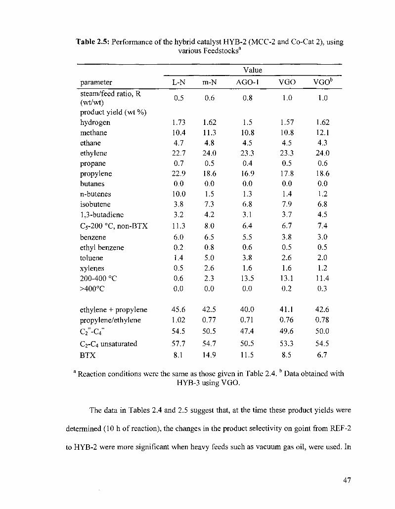
Table 2.5: Performance of the hybrid catalyst HYB-2 (MCC-2 and Co-Cat 2), using various Feedstocks3
Fig.2.2: Assumed intervention level (IL) of the hydrogen spilt-over species (being produced in situ on the co-catalyst surface) on the reaction intermediates at the cracking
sites
(c) The fact that, after 10 h time-on-stream (a very short period of time), the
hybrid catalysts had almost little effect on lighter hydrocarbon feedstocks, whereas
heavier feedstocks were significantly affected, suggests that the dearomatization of these
existing polynuclear aromatics was predominant, compared to the retarding effect on
their formation from smaller hydrocarbons of the feed (Fig.2.2).
Table 2.6: Tabulated results for the DTA/TGA analysis of reference (REF-2) and hybrid (HYB-2) catalysts in various environments3
parameter
REF-2
in argon
Value
in air
HYB-2
in argon in air
weight loss temperature assumed type of reaction (DTA)
a Reaction conditions were the same as those of Table 2.4. Results were obtained with a L-N feed
Note that the hybrid catalyst HYB-1(4) showed yields in product light olefins that
are much lower than those of HYB-2 (see Tables 2.7 and 2.5, respectively). They both
contained the same co-catalyst (Co-Cat 2), but they differed from each other by the main
catalyst component (i.e., MCC-1 and MCC-2) used in the preparation of the final catalyst
53
(HYB-1(4) and HYB-2, respectively). On the MCC-1 surface, the cracking sites were
acid sites developed by the M0O3 species [82] deposited on quasineutral yttria-stabilized
alumina aerogel (AAS; see Table 2.1). Such surfaces (MCC-1 and AAS) do not show any
significant Bransted acidity (1546 cm"1) besides the Lewis acid sites (1450 cm"1) [83]
(see Fig.2.3C and Fig.2.3A). Instead, the lanthanum stabilized ZSM-5 zeolite was used in
the preparation of the MCC-2 whose surface exhibited, compared to that of the MCC-1, a
larger amount of Bransted acid sites (see Fig.2.3D), a higher acid sites density (Table
2.1), and a higher density of slightly stronger acid sites (see Table 2.1; higher density and
slightly higher desorption temperature for peak S). The major contributor to this
enhanced acidity was the ZSM-5 zeolite (see Fig.2.3B and Fig.2.4).
Wavenumber (cm4)
Fig.2.3: FT-IR spectra of adsorbed pyridine of the main components (MCC-1 (spectrum C) and MCC-2 (spectrum D)) and their corresponding "active" supports (AAS (spectrum
A) and ZSM-5 zeolite (spectrum B))
54
<5
100 2® 300 400 50ft 6O0
Temperature (°C)
Fig.2.4: Acid strength profile obtained using the NH3-TPD/ISE method: (A) H-ZSM5, (B) MCC-2, and (C) MCC-1. (A)) d[NH4]/dt (given in units of mmol g"loC"')
Therefore, to have the same level of conversion, catalytic testing was performed
on the HYB-1(4) (and other catalysts using the same AAS support) at a significantly
higher temperature (i.e., 740'C instead of 725 °C; see Fig.2.1 and Table 2.7). Such higher
reaction temperature led to a lower product propylene/ethylene ratio (Fig.2.1 and Table
2.7), as usually observed with thermal or steam cracking. Thus, the use of ZSM-5 zeolite
containing hybrid catalysts, tested at the standard reaction temperature (725 °C) and
particularly with light hydrocarbon feedstocks, resulted in a higher combined yield of
ethylene and propylene and a higher propylene/ethylene ratio (Table 2.5, L-N as feed).
According to Corma et al., [84] in the FCC naphtha cracking, the selectivity to propylene
increases when hydrogen-transfer reactions are minimized using shape-selective catalysts
(such as the ZSM-5 zeolite). However, we believe that, in our case, the use of higher
temperature to compensate the lower surface acidity of the nonzeolitic main component
such as in the HYB-1(4) was the main cause for such significant variations of the
propylene/ethylene ratio.
55
2.4. CONCLUSION
We have shown in this work that the hydrogen spill-over effect may play a key
role in improving the catalytic activity of the hybrid catalysts of the TCC process.
Because the latter process has been developed for the production of light olefins, this
effect, when fully controlled, may advantageously contribute to (i) increasing the yields
of light olefins, (ii) producing less heavy compounds, and (iii) lengthening the run length
when a fixed bed (and tubular) reactor is used.
The concept of hybrid catalysts that contain co-catalysts being capable of
producing hydrogen spill-over species is proven to have powerful dearomatizing/ring
opening properties. Therefore, the use of such catalysts may reduce polynuclear
aromatics in middle-distillate fuels, which are known for "producing particulates in the
exhaust gases and, in addition, having poor ignition properties (i.e., low cetane number in
diesel fuel and high smoke point in jet fuel)". [85] More-efficient hydrotreating catalysts
would be prepared using this concept of long-distance hydrogen spillover. [75, 86]
Finally, note that recent progress in the understanding of these hydrogen spillover
phenomena will result in very important applications in several sectors of catalysis, fuel-
cell technology, and material science. [87-90]
2.5. AUTHOR'S NOTES AND SIGNIFICANCE OF PAPER TO THESIS
This work on the phenomena of the hydrogen spill over was the first article
published in the literature on the effect of the spilt-over hydrogen species on the product
yields of the hybrid catalysts used in the thermo-catalytic cracking (TCC) process for the
production of light olefins. The Ni bearing co-catalyst was found to be able to produce
very active hydrogen species by steam reforming. Once these species were transferred
56
(spilt-over) onto the surface of the main catalyst component (cracking sites), they could
interact with the adsorbed reaction intermediates, resulting in a decreased rate of coke
formation and the dearomatization/ring-opening of some heavy compounds of the feed.
Although the amounts of these hydrogen spilt-over species were very small, their effect
on the conversion of heavy feedstocks (such as vacuum gas oils) was very significant.
The following chapter shows the influence of hydrogen spilt-over species on the
cracking of model molecules (n-hexane) at the level of the zeolite acid sites. It is well
known that hydrogen spilt-over species play an important role in the retardment of coke
formation and the improvement of the stability of catalyst. However, the nature of these
hydrogen species remains unknown. Therefore, the Thermo-Catalytic Cracking
performance of the hybrid catalyst on n-hexane containing some polymethylbenzenes
will be investigated in order to determine the effect of coke precursors
(polymethylbenzenes) on the reactivity of the zeolite component. This study also will
allow us to estimate the maximum distance at which the hydrogen spilt-over species
remain effective.
57
Chapter I I I
The Thermo-Catalytic Cracking of Hydrocarbons: Effect of Polymethylbenzenes Added to the //-Hexane Feed on the Reactivity of ZSM-5 Zeolite Containing Hybrid Catalyst
Published as:
H. T. Yan and R. Le Van Mao
Catal. Lett. (2009) 130:558
58
3.1. INTRODUCTION
The thermo-catalytic cracking process (TCC) has been recently developed to
crack heavy hydrocarbon feedstocks (naphthas, gas oils) [91, 92] or heavy olefins [93]
into propylene, ethylene and other light olefins. The most recent TCC catalysts have a
hybrid configuration, comprising a main (acidic) component and a co-catalyst. [91-93]
Modified ZSM-5 zeolite is the acidic component while the co-catalyst is obtained by
dispersing a noble metal (Pt or Pd) or Ni on a hydrothermally stable support. The role of
the co-catalyst is to prevent or slow down the normally rapid formation of coke due to
cracking and related reactions at relatively high temperatures. Ni bearing co-catalyst is
capable of producing some active hydrogen species by steam-reforming. [92] These
species might be then split-over (HSO) onto the main acidic catalyst surface with, as a
final result, a significant retarding effect on the formation of coke precursors, i.e.
polycyclic aromatic hydrocarbons (PAH). [91, 92] It is to note that the heavy PAH are
already present in the feed, alongside with BTX aromatics and some
polymethylbenzenes, or can be formed during the reaction.
More than a decade ago, it was shown that the formation of various hydrocarbons
from methanol proceeded via a hydrocarbon pool mechanism [94-96] rather than via an
initial C-C bond formation. [95, 97] The quite complicated reaction pattern as depicted in
the pool mechanism, was recently evoked to explain the delayed coking effect in the
thermo-catalytic cracking (TCC) of hydrocarbons that made use of hybrid catalysts. [92]
It is to note that such PAH may derive from heptamethylbenzenium ion (HMB+), the
main reaction intermediate being hypothesized in the pool mechanism. This ion is
assumed to "control" not only the formation of gaseous products but also that of coke.
59
[98] However, in a more recent paper, Bjorgen et al. [99] showed that with ZSM-5 zeolite
catalysts, the mechanism of methanol conversion to hydrocarbons was more complicated
than that previously proposed.
In the present work, to the «-hexane (feed currently used to study the TCC
reaction) is added in increasing amount, one of these two polymethylbenzenes (P-
methylbenzenes): pentamethylbenzene (PMB) or 1,2,4-trimethylbenzene (TMB). The
former co-fed molecule is too bulky to be sorbed by the zeolite micropores whereas the
latter has a molecular diameter small enough to allow a significant sorption onto the
internal surface of these micropores. In addition, the size of the TMB molecules is such
that some of them can remain trapped inside these micropores.
Thus, the expected results are:
What kind of disturbance the co-fed TMB can create on the catalytic performance
(product yields or selectivity)?
More importantly, what is the range of action of these hydrogen species (HSO),
formed on the co-catalyst surface and spilt-over onto that of the zeolite bearing
component? Can these HSO reach the internal surface of the zeolite micropores?
3.2. EXPERIMENTAL
3.2.1. Catalyst Preparation
Both hybrid and reference catalysts were prepared according the method
described in the previous papers. [91, 92]
3.2.1.1. Main Catalyst Component (M-Cat)
Fifty gram of HZSM-5 (powder, acid form, silica/alumina molar ratio = 50,
purchased from Zeochem, Switzerland) were added to a solution that was composed of
60
25.0 g of lanthanum nitrate hydrate (Strem Chemicals) in 500 mL of deionized water.
The suspension, gently stirred, was heated to 80 °C for 2 h. After filtration, the obtained
solid was washed on the filter with 500 mL of water, then dried at 120 °C overnight and
finally activated at 500 °C for 3 h. This material was called La-HZSM-5.
A solution of 5.52 g of ammonium molybdate hexahydrate (Aldrich) in 89 mL of
2.3 N H3PO4 was homogeneously impregnated onto 40.02 g of La-HZSM-5. The solid
was died at 120 °C overnight and finally activated at 500 °C for 3 h.
Its chemical composition was as follows: M0O3, 8.0 wt%; La203, 2.5 wt%;
phosphorous, 4.1 wt%; and zeolite, balance.
3.2.1.2. Co-Catalyst (Co-Cat)
A mixture of 2.59 g of nickel nitrate hexahydrate (Strem) in 20 mL of deionized
water and 0.036 g of ruthenium acetylacetonate (Strem) in 25 mL of methanol was
homogeneously impregnated onto 20.0 g of yttria-stabilized alumina aerogel, Y-AA. [92]
After drying at 120 °C overnight, the solid was activated at 500 °C for 3 h. Its chemical
It is to note that the surface areas corresponding to pores larger than the
micropores in the catalyst extrudates (Z-REF and Z-HYB), represented important
fractions of the total surface area (40 and 38%, respectively). It is also reasonable to
assume that the surface area of the micropores of the hybrid catalyst came mostly from its
zeolitic component whose particle showed the same proportion for large pores (36%). All
this means that the external surface of the zeolite particles (which also includes that of the
large micropore openings) was quite significant.
The incorporation of La onto the ZSM-5 zeolite particles and that of (P-Mo)
species had as main objectives to decrease the strength of the zeolite acid sites,
particularly those located on the external surface [102] and to create new larger pores
with moderately acidic surface [93], respectively. These large pores were located in the
outer-skirt of these zeolite particles and the corresponding mild acid sites were destined
to crack large molecules of the feed.
Catalytic data of the hybrid catalyst (HYB) and its reference (REF) reported in the
following sections were average values obtained during a period of time of 5 h (after an
64
initial period of 5 h, needed for stabilizing the catalytic reaction). We preferred using
mixtures of «-hexane with poly-methylbenzene in increasing and significant
concentration. This is because, in the case of TMB that could be adsorbed and trapped
inside the micropores of the ZSM-5 zeolite particles, the effect on the conversion of the
TMB, added in small amounts (for instance, 0.3 wt%) to «-hexane, would take too much
time (16 h and more) to be noticed.
3.3.1. Tests with Pentamethyl Benzene (PMB) Added to n-Hexane Feed
Fig.3.1 shows the variation of the conversion of the feed (rc-hexane + PMB)
versus the weight percent of PMB added to the «-hexane. It appears that there was almost
no difference between the two curves drawn for the two catalysts (Z-HYB and Z-REF).
The same behaviors were reported for the yields of light products (Fig.3.2) and the heavy
products (Fig.3.1).
80 70
g 60 '« 50 u £ 40 o 30 o
20 10 0
0 4 8 12 16 PMB
I - 0 - Z-HYB - " - Z - R E F ]
Fig.3.1: Total conversion (wt%) versus concentration (wt%) of PMB in hexane
65
I
70
60
50 +
40
30
20
10 +
0
0
— h -
8 PMB
12 16
•Z-HYB "Z-REF
Fig.3.2: Product yield (wt%) in C1-C4 hydrocarbons versus concentration (wt%) of P M B in hexane
8
PMB
12 16
"Z-HYB "Z-REF
Fig.3.3: Product yield (wt%) in heavy hydrocarbons versus concentration (wt%)
of P M B in hexane
It is wel l-known that the ten-rings micropores of the ZSM-5 zeolite have average
sizes of 0.55 nm for straight channels and 0.53 nm for sinusoidal channels: thus, these
pores reject all guest molecules having critical dimensions larger than 0.78 nm. [103]
66
PMB having a critical diameter larger than 0.78 nm (same as 1,3,5-trimethylbenzene)
[104, 105] is obviously excluded from these zeolite channels, i.e. from all the surface
areas of the Z-HYB and Z-REF assigned to micropores (Table 3.1). In our tests, if PMB
had had some effect on the conversion and products yields, it would have expressed such
effect on the surface of larger pores, i.e. the external surface of the zeolite particles which
hosted the acid sites active for cracking.
Although there was no apparent difference in activity between the two catalysts
(Figs. 3.1, 3.2, 3.3), the co-catalyst of the hybrid catalyst exhibited lower coke deposition
(Fig. 3.4) and lighter coke nature, i.e. lower combustion temperature for coke (Fig.3.5)
than the reference catalyst. This was another evidence of the influence of the hydrogen
split-over species produced by the steam-reforming over the active Ni sites of the co-
catalyst of the Z-HYB. Such Ni sites were not present in the Z-REF sample. [91, 92]
50
45
40
.S 35 o
° 30 25 20 15
1 -O-Z-HYB -"-Z-REF |
Fig.3.4: Coke deposition (wt%) versus concentration (wt%) of PMB in hexane
67
0 4 8 12 16 PMB
8
PMB
12 16
-Z-HYB •Z-REF
Fig.3.5: Combustion temperature of coke (T in °C) versus concentration (wt%) of PMB in hexane
3.3.2. Tests with 1,2,4-Trimethylbenzene (TMB) Added to n-Hexane Feed
Fig.3.6 reports the variation of the conversion versus the content of 1,2,4-
trimethylbenzene in the feed.
12 16 TMB
•Z-HYB •Z-REF
Fig.3.6: Total conversion (wt%) versus concentration (wt%) of TMB in hexane
The catalytic behaviours of both catalysts (Z-HYB and Z-REF, Fig.3.6) were
68
extremely different from those reported in Fig.3.1 where the n-hexane feed contained
various concentrations of PMB. In addition, there was a significant difference in catalytic
behaviour (conversion and product yields) between the Z-HYB and Z-REF samples
(Figs. 3.6, 3.7, 3.8). To ensure that the obtained graphs were not due to experimental
errors (normally lower than 0.5% for all the data), several tests for each set of
experimental parameters were carefully performed and the average values were reported
in the graphs.
The interpretation of these catalytic data were based on the critical dimension and
kinetic diameter of the 1,2,4-trimethylbenzene (TMB), that were estimated equal to
0.8 nm [104, 105] and 0.61 nm [106], respectively.
Whereas PMB could not enter the ZSM-5 zeolite channels, the TMB having a
narrower molecular size, could instead diffuse into these micropores. [100, 101]
According to Choudary et al. [100], the inward diffusion of the 1,2,4-trimethylbenzene
was possible in most situations while the outward diffusion of such molecule could be
difficult. Therefore, a certain accumulation of TMB inside the ZSM-5 channels could
occur at a significant TMB concentration in the feed.
Let us consider the graphs of the variation of the conversion versus the
concentration of TMB in the feed as reported in Fig.3.6.
With the reference catalyst (Z-REF), there was a sharp decrease of the total
conversion (much sharper than with the feed containing PMB, Fig. 3.1) because some
TMB was rapidly adsorbed inside the ZSM-5 channels, inducing some partial pore
blockage. Over 8 wt% of TMB, when the (partial) zeolite pore blockage by the adsorbed
TMB became more serious, only the external surface of the zeolite was fully exposed to
69
the reactant (rc-hexane and TMB), so that the activity decay was now mainly due to the
cracking reaction on the external surface of the zeolite particles.
With the hybrid catalyst (Z-HYB), there was a certain resistance to activity decay
induced by hydrogen spillover (HSO), up to a concentration of 4 wt% of TMB. Then the
accumulation of TMB inside the ZSM-5 micropores resulted in almost the same profile
of variation of the total conversion as with the Z-REF catalyst. However, such conversion
minimum was shifted to higher value of TMB concentration. Over 8 wt% of TMB in
hexane, there was some kind of return to the situation as previously observed with PMB
at high concentrations in the «-hexane feed: the difference in the total conversion was
mostly related to the catalytic activity on the external surface of the Z-HYB and Z-REF
samples. Finally, at a concentration of TMB higher than 12 wt%, the conversion (Fig.3.6)
and the yields in C]-C4 and heavy products (Figs.3.7, 3.8) of the Z-HYB catalyst were
significantly higher and more stable than those shown by the Z-REF sample, suggesting
thus some noticeable influence of the hydrogen split-over species.
70
12 16
TMB
-Z-HYB •Z-REF
Fig.3.7: C1-C4 product yield (wt%) versus concentration (wt%) of TMB in hexane
3
2.5
2
f 1. 5 CD 1
•5 x 0. 5
0
10 12 TMB
"Z-HYB "Z-REF
Fig.3.8: Heavy product yield (wt%) versus concentration (wt%) of TMB in hexane
Remarkably, all the variations of the conversion (and product yields: Figs.3.6, 3.7,
3.8) were closely reproduced in Figs.3.9 and 3.10 that compare the amounts of the
deposition of coke and its nature (combustion temperature), respectively.
71
40 r
30 CD
•o 20
10 -
0 I ' ' ' ' 0 4 8 12 16
TMB ^^Z-HYB -»-Z-REF
Fig.3.9: Amount of coke deposited (wt%) versus concentration (wt%) of TMB in hexane
550
540
530
E- 520
510
500
490
0 4 8 12 16
TMB
I - >-Z-HYB -"-Z-REF 1
Fig.3.10: Combustion temperature of coke (T in °C) versus concentration (wt%) of TMB in hexane
3.4. CONCLUSIONS
The use of two different polymethylbenzenes, the pentamethylbenzene (PMB)
and the 1,2,4-trimethylbenzene (TMB) co-fed with n-hexane, has allowed us to draw the
following conclusions:
72
1. Data of total conversion and yields of C1-C4 cracking products show that the hybrid
catalyst (Z-HYB) having steam-reforming Ni sites located on the co-catalyst surface,
performs significantly better than the reference catalyst (Z-REF). This is another
experimental evidence of the action of the hydrogen split-over (HSO) species. [91,
92] In addition, compared to the reference catalyst (Z-REF), the lower amount and
the lighter nature of the coke deposited onto the hybrid catalyst, assure to the Z-HYB
a longer catalyst "on-stream" stability and an easier catalyst regeneration (by coke
combustion), respectively. These properties are particularly useful in the TCC
conversion of heavy liquid hydrocarbons. [91, 92]
2. With respect to the Z-REF, the improvement of the catalytic activity of the Z-HYB in
the presence of the («-hexane/TMB) feed, mostly at high concentration of TMB
(higher than 12 wt%), is more important than when the («-hexane/PMB) feed is used.
This is in agreement with the hydrocarbon pool mechanism in which "the reaction
mainly proceeds via penta-and hexamethylbenzene" as coke precursors. [102]
Adsorbed TMB being less methylated than PMB is relatively far from turning into
coke and thus, may lead to a larger difference in reactivity between the Z-HYB and
Z-REF catalysts. This recalls the most recent and extremely interesting paper of
Bjorgen et al. [94] who showed that over ZSM-5 zeolite catalysts there might be two
reaction cycles, one through a "modified hydrocarbon pool mechanism" (for lower
methylbenzenes) and the other one, going through alkene methylation and
interconversions.
3. The unusual behavior of the Z-HYB catalyst when converting the «-hexane/TMB
feed is due to the accessibility of the TMB into the zeolite micropores of the main
73
component and its difficulty to move out of such pore system. This also shows the
limitation in the motion of the hydrogen split-over species that can be transferred
from the co-catalyst surface to the external surface of the ZSM-5 zeolite particles, but
not inside the small pores of such zeolite.
These results may have important applications in the TCC process and others,
where HSO action is required to continuously clean the acidic active surface (cracking)
of the catalyst. If the acidic component is a mesoporous material [103] instead of a
microporous zeolite, can the HSO effect be more efficient?
3.5. AUTHOR'S NOTES AND SIGNIFICANCE OF PAPER TO THESIS
This work on the effect of hydrogen spilt-over species was the first article in the
literature showing the effect of polymethylbenzenes (added to the «-hexane feed) on the
reactivity of the ZSM-5 zeolite containing hybrid catalysts. The results of this study
indicated that the hydrogen spilt-over species could be transferred from the co-catalyst
surface to the external surface of the main catalyst (ZSM-5 zeolite) particle; however,
they could not penetrate the small pores of that particle. Thus, the hydrogen spilt-over
species could affect the reaction intermediates only when the latter were formed on the
external surface of the zeolite particle.
The following chapter is a continuous effort toward the understanding of the coke
of the zeolite component within the hybrid catalyst. In the next chapter, we will be
exploring the influence of the pore characteristics and the acidity properties of the ZSM-5
zeolite-based component on the overall performance of the hybrid catalysts.
74
Chapter IV
Hybrid Catalysts Used in the Thermo-Catalytic Cracking Process (TCC): Influence of the Pore Characteristics and the Acidity Properties of the ZSM-5 Zeolite-Based Component on the Overall Performance
To be submitted to: Applied Catalysis: A
H. T. Yan and R. Le Van Mao
75
4.1. INTRODUCTION
Ethylene and propylene are the most important intermediates used in the
production of main plastics and synthetic fibres. [109] The current technology of
production of these olefins is steam-cracking, using various hydrocarbon feedstocks
(light paraffins, naphthas or gas oils). Setting aside this special period of economic
recession, market demands for ethylene and propylene have experienced significant and
constant increases, with a higher growth rate for propylene. [110] However, because the
product selectivity of the steam-cracking for propylene is quite low, the supply of this
light olefin can be compensated through the use of other production processes, such as
Liquid and gaseous products were collected separately, using a system of
condensers. The gas-phase components were analyzed using a Hewlett-Packard Model
5890 FID gas chromatograph that was equipped with a 30-m GS-alumina micro-packed
column (J & W Scientific), whereas the analysis of the liquid phase was performed using
a Hewlett-Packard gas chromatograph (Model 5890, with flame ionization detection
(FID)) that was equipped with a Heliflex AT-5 column (Alltech, 30m, nonpolar).
The total conversion (wt %) was expressed as the number of grams of all the
products collected at the reactor outlet, by lOOg of feed, referring to n-hexane or
eventually to the mixture of n-hexane and 1,3,5-TMB, therein called FEED, as follows.
81
Conversion (wt %) = [(FEEDin - FEED0Ut)/FEEDin] 100 (wt %), with FEED in
and FEED out being the total weight of («-hexane and eventually, 1,3.5-TMB) injected
into the reactor and the unconverted feed determined in the reactor out-stream,
respectively.
The selectivity of product i (Yj) was expressed as the number of grams of product
i recovered, by 100 g of total products collected (wt %). It is important to note that the
experimental error usually observed on total conversion and calculated product selectivity
was ± 0.2 wt %.
4.3. RESULTS AND DISCUSSION
4.3.1 Main physico-chemical properties of the hybrid catalyst components
In our previous paper [109], the main chemical properties of the two
components of the hybrid catalyst, the acidic ZSM-5 zeolite and the Ni bearing support
(Y-alumina aerogel or Y-AA), were reported. In the present paper, the pore
characteristics and the surface acidity properties were carefully investigated because they
were believed to have a great influence on the overall catalytic performance.
4.3.1.1 Determination of the extent of the external surface area of the ZSM-5 zeolite particles:
Table 4.1 reports the results of the BET analysis of the various hybrid catalysts
and their corresponding references. Herein, the BET surface area corresponding to the
micropores was assigned to the internal surface of the zeolite particle whereas that of
larger pores was attributed to its external surface. Thus, the external surface included the
surface area that was external to the zeolite particle, and the surface area corresponding to
that of the (large - sized) mouths of the micropores.
82
Except for the very SiC>2 rich 1000H sample, all these other ZSM-5 samples or
corresponding catalysts showed an external surface area higher than 1/3 of the total
surface area (Table 4.1): on such "open" surface, the catalytic reaction was not submitted
to the same constraints (shape-selectivity) as on the micropores-related internal surface. It
is to note that the SAR values (external to internal surface area ratio) of the hybrid
catalysts and their corresponding references showed the same variation trend (with with
increasing zeolite SiC^/A^Ch ratio) as that of the parent zeolites, the co-catalyst or co-
catalyst support being incorporated in the same percentage.
83
Table 4.1: BET Surface Areas of Various Catalyst Components or Catalysts Used in This Work (SAR = external/internal surface area ratio)
Si02/Al203 Total Internal External (m2/g) (m2/g) (m2/g) (%)
SAR
Zeolite (powder) 25H 50H 100H 400H 1000H
Co-catalyst support Y-AA (powder)
Catalysts (extrudates) 25HYB 25Ref
50HYB 50REF
100 HYB 100 REF
400 HYB 400 REF
1000 HYB 1000 REF
22 37 98
443 765
0
420 403 497 361 408
270
187 213
200 205
196 214
185 183
173 216
270 262 229 231 235
18
116 127
124 129
87 91
121 89
89 144
150 141 268 130 173
252
71 86
76 76
109 123
61 94
84 72
36 35 54 36 24
93
38 40
38 37
56 57
33 52
49 33
0.56 0.54 1.17 0.56 0.74
14
0.61 0.68
0.61 0.59
1.25 1.35
0.5 1.06
0.94 0.5
4.3.1.2 Surface acidity characteristics
Table 4.2 reports the data of surface acidity of the same samples. The two
characteristics shown are the density of acid sites and the distribution of these sites
according to their strengths. We also made the assumption that these acid sites were
homogeneously distributed on all over the surface of the zeolite particle, so that the
external/internal surface area ratio (SAR) previously calculated in Table 4.1 is also the
84
distribution ratio of the acid sites on the external surface to those of the internal surface of
the zeolite particle. In terms of acid strength, as expected, a zeolite material with higher
Si/Al atom ratio provides stronger acid sites that corresponded to higher desorption
temperatures for pre-adsorbed NH3. It is to note that the ISE method used for the
investigation on the distribution of the acid site strength, was not sensitive enough to
detect the very low concentration of the desorbed NH3 (case of 1000H and related
materials). However, it is not illogical to say that, by considering the trend in the strength
distribution in Table 4.2, most of the acid sites of the 1000H zeolite were strong: this
statement was later confirmed by the qualitative investigation of the acid sites using the
FT-IR technique applied to pre-adsorbed pyridine (Fig.4.1 to Fig.4.3, in the following
section).
85
Table 4.2: Surface Acidity Properties of Parent ZSM-5 Zeolites and Corresponding Catalysts (The density of acid sites was obtained by back-titration method and the
distribution of acid site strength (zeolites) was determined by ISE method.)