Page 1
American Institute of Aeronautics and Astronautics
1
The Trick Simulation Toolkit: A NASA/Open source
Framework for Running Time Based Physics Models
John M. Penn1
L-3 Communications, Houston, Texas, 77058, USA
Alexander S. Lin2
NASA Johnson Space Center, Houston, Texas, 77058, USA
This paper describes the design and use at of the Trick Simulation Toolkit, a
simulation development environment for creating high fidelity training and engineering
simulations at the NASA Johnson Space Center and many other NASA facilities. It
describes Trick's design goals and how the development environment attempts to
achieve those goals. It describes how Trick is used in some of the many training and
engineering simulations at NASA. Finally it describes the Trick NASA/Open source
project on Github.
I. Introduction
he Trick Simulation Toolkit is a simulation development environment used to create high fidelity training
and engineering simulations at the NASA Johnson Space Center and many other NASA facilities. Its
purpose is to generate computer simulations that have a common architecture from a collection of user-supplied
model code and a simulation definition file. In doing so, Trick provides automated job scheduling for user-
supplied model functions, numerical integration, the ability to write and restore human readable checkpoints,
data recording, interactive variable manipulation, a run-time interpreter, and many other commonly needed
capabilities. Also included in Trick are tools for plotting recorded data and various other supporting utilities and
libraries. Trick is written in C/C++ and Java and supports both Linux and MacOSX computer operating
systems.
II. The Goal of Trick
The goal of Trick is to help simulation developers focus on their domain and the algorithms and equations of
their problem rather than repeatedly solving the same, time consuming architecture problems and re-
implementing required capabilities. Trick seeks to reliably1 accomplish this by automating the implementation
of commonly needed simulation capabilities and by automating the build process of the executable.
III. The Simulation Definition (S_define) File
In order to accomplish the desired automation, Trick needs to "learn" about the specific variables, data
types, functions, and scheduling requirements of a simulation's models. This starts with the simulation
definition file (S_define), an example of which is shown in Figure 1 below. This example comes from a
simulation included in the Trick software distribution, called SIM_cannon_integ. It is a very simple simulation
of a cannon ball in flight.
1 Senior Engineer, 1002 Gemini St, Suite 200 2 Aerospace Engineer, 2101 NASA Parkway
T
https://ntrs.nasa.gov/search.jsp?R=20150021786 2018-07-13T08:41:29+00:00Z
Page 2
American Institute of Aeronautics and Astronautics
2
Figure 1 - Example S_define File
An S_define file specifies everything necessary to build a simulation:
Data types
Variable definitions
Job scheduling specifications
Compilation unit dependencies
In the S_define, data type information is provided by model header files (preceded by ##include) and
Trick::SimObject class definitions.
Trick::SimObject is a special class (a data-type) for grouping related data members (e.g., cannon above) and
job scheduling specifications of a simulation component. The state of a Trick simulation is represented by a
collection of SimObject instances, variables of type Trick::SimObject. Some SimObjects and instances are
already defined by Trick to provide standard simulation features. In the example above, these are included from
"default_trick_sys.sm.” A simulation developer creates the remaining SimObjects and instances thereof to fully
define the simulation.
The last two lines of the S_define in the example above are variable definitions. The variable dyn is an
instance of CannonSimObject. The variable dyn_integloop is an instance of IntegLoop that is executed every 10
milliseconds and operates on dyn. The cannon data member within dyn is accessed as dyn.cannon.
The source files specified in LIBRARY DEPENDENCIES are the starting point for the recursive
determination of the files that need to be compiled and linked to build the simulation. Trick headers in these
files may specify additional source code dependencies, and so forth. Libraries may also be specified for linking
into the final simulation executable.
IV. Providing Access to Simulation Variables
Central to automating access to simulation variables are:
Page 3
American Institute of Aeronautics and Astronautics
3
Descriptions of a simulation's variables and data types
The ability to translate between a variable's name and its address
The ability to translate a variable's name to its address allows a Trick simulation to automatically provide
various system components (both internal and external) with access to its variables by name. This capability
allows Trick to automate and provide the following capabilities:
Input-processor
Data recording
Restoration of the simulation state from a checkpoint file
A variable-server, which provides network access to simulation variables
The variable server enables the implementation of networked simulation clients such as:
Trick Sim Control Panel
Trick View
StripChart
Many of Trick’s users also implement their own project-specific variable server clients for monitoring and
control of their simulations.
The opposite translation, from an address to a name, allows a Trick simulation to automatically represent
variables in a human readable form, as is done when writing a checkpoint. A checkpoint is a textual, human-
readable representation of a simulation's state. At any time during the execution of a Trick simulation, one can
write a checkpoint to file. A simulation’s state can also be restored from a checkpoint file.
SWIG (the open-source interface compiler) provides access to variables for Trick's embedded Python
interpreter. ICG (Trick's interface code generator) and Trick's Memory Manager provide access for the
remaining capabilities listed above.
Data type information is determined by scanning the SimObject classes and the header files listed in the
S_define file. This also includes recursively scanning any files that they may include. Variable definitions (i.e.,
declarations that actually create variables) are also scanned and recorded from the S_define file. This data
collection occurs when the utility Trick-CP is invoked to build a simulation. Trick-CP calls both SWIG and
ICG to gather information about variables and data-types and to record that information in the form of
generated interface code.
A. SWIG, Python and the Input Processor
By scanning and processing SimObjects and header files, SWIG can generate auto-coded interfaces to
simulation variables and functions for Trick's embedded Python interpreter, referred to as the "input processor."
The primary purpose of the input processor is to allow a user to conveniently configure a simulation run.
Because it provides access to simulation framework variables and functions, as well as those of the simulation
models, it provides a great deal of control.
B. Trick's Interface Code Generator (ICG)
Trick's Interface Code Generator (ICG) also scans simulation header files for data type information, which
it encodes within C-language tree structures of ATTRIBUTES records within generated "io_src" interface code.
Arrays of ATTRIBUTES records are used to encode the elements of user defined data types (that is: struct and
class). They can also represent arrays of and pointers to these types in addition to primitive types. The elements
of an ATTRIBUTES record are as show in Figure 2 below:
Page 4
American Institute of Aeronautics and Astronautics
4
Figure 2 - ATTRIBUTES Record
name represents the name of an element of a user-defined data type.
type indicates whether the element is a primitive or a composite type. Think of it as the "type" of data-
type.
type-name is the C/C++ data-type of the element.
offset specifies the location of the element within its parent. If the element's data-type is composite, then
attr points to the ATTRIBUTES array that describes it otherwise, this element = NULL.
num_index specifies the dimensionality of the element. If num_index is non-zero, then
index specifies the size of each array dimension.
In Figure 3 are four examples of data-type encoding with ATTRIBUTES:
Figure 3 – Examples of Data Type Encoding Using ATTRIBUTES
C. The Memory Manager
Access to variables is provided by names or addresses. A variable’s data type describes how its values are
represented in memory. In Trick, the ALLOC_INFO data type represents the "knowledge" of a variable.
Figure 4 - How Variables are Represented
Page 5
American Institute of Aeronautics and Astronautics
5
Trick's Memory Manager represents all of a simulation’s state variables as a collection of ALLOC_INFO
records. Every instance of a Trick::SimObject defined in the S_define file will have an associated
ALLOC_INFO record. Any other variables that have been explicitly defined or declared using calls to the
Memory Manager will also have ALLOC_INFO records. Here, declare means to provide a data-type and an
address to tell the Memory Manager that a variable exists. Define means to provide a data-type and request to
the Memory Manager to create (allocate) a new variable. A simulation's data types are gleaned from the header
files (.h or .hh files) included by its S_define file.
D. An Example Representation of a Variable
Using Circle__attributes from the Example 3 of Figure 3 above, an instance of Circle named pad whose radius
= 7 and whose center is at (4,5) would be represented in the Memory Manager as shown in Figure 5:
Figure 5 - Example Representation of a Variable
E. Translating Variable References
The Memory Manager’s ALLOC_INFO list and ICG-generated ATTRIBUTES provide the necessary
information to translate references in both directions.
Using the example of the pad variable in Figure 5 above, the two examples below illustrate how these
translations are performed.
Figure 6 – With Address Calculations
Suppose for the sake of these examples that the address of the pad allocation is 1000.
1. Example Translation of an Address to a Name
To translate the address 1008 to a name, the memory manager searches for the ALLOC_INFO record whose
address is less than or equal to 1008 and whose address + size is greater than 1008. It's found, and its name is
pad, so the name of the translated addresses starts with pad. Stepping into the ATTRIBUTES, we see the first
element radius. We add its offset to the address of pad and compare it to 1008. It's not the address we're looking
for, so we move on to center and check the sum of the address of pad and the offset of center. The addresses
match. So far the name we've accumulated is pad.center, but center is TRICK_STRUCTURED, meaning it's a
Page 6
American Institute of Aeronautics and Astronautics
6
composite variable, so we have to look at its ATTRIBUTES. The first element, with offset of 0, is x. So, the
final name is pad.center.x. The name that corresponds to address 1008 is pad.center.x.
2. Example Translation of a Name to an Address
To translate the name pad.center.y to an address, the memory manager searches for the ALLOC_INFO record
whose name is pad. In this case, its address is found to be 1000. Following the period, in the name is center. So
we next search for center in the ATTRIBUTES array. Its offset is 8, which we add to the address of pad.
Remaining in the name is y. Because center is a composite variable, it too has an ATTRIBUTES array. We
search it to find y, and we add its offset to the address for a final result of 1016. So, the address that corresponds
to pad.center.y is 1016.
The data-type of y is double, so Trick can print its value as:
printf("%g", *(double*) 1016 );
By maintaining a complete representation of the simulation state, ICG, the Memory Manager, and SWIG make
it possible for Trick to automatically provide the input-processor, data recording, checkpoint and checkpoint-
restore, the variable-server, and the various client applications.
V. Job Scheduling
A job is a call to a user-supplied C/C++ function that is scheduled in accordance with its specified job
class. A job class dictates the circumstances under which a job's associated function is executed. It may also,
with additional parameters, specify a job rate, priority, start time, stop time, and thread of execution.
The Trick executive maintains numerous job queues. With the exception of instrumentation jobs, which can
appear in any job queue, a job class indicates to which of the scheduler's job queues a particular job belongs.
Also, with the exception of checkpoint job queues, all queues are associated with one of Trick's four basic
simulation modes:
1) Initialization
2) Run
3) Freeze
4) Exit
A. Initialization Mode
The initial job-scheduling mode of a
Trick-based simulation is Initialization.
Its purpose is to initialize the simulation
and Trick's system components. The
behavior of the job scheduler during
Initialization-mode is show in Figure 7.
Initialization Mode and described below.
Simulation time is maintained as integer
time_tics. The parameter time_tic_value
specifies the number of tics per second.
software_frame is another parameter
which stipulates how often the job
scheduler synchronizes with external
services such as data recording and (if
enabled) a real-time clock. Both
time_tic_value and software_frame
parameters can be user-specified.
Associating a function to the job class
default_data places it in the default-Figure 7. Initialization Mode
Page 7
American Institute of Aeronautics and Astronautics
7
data-job-queue, causing it to be executed first, during initialization mode. Default-data jobs are meant to set the
default simulation state. If specified in the S_define, they always run first, before any other job class.
In addition to the job classes available to a developer, Trick's main job scheduler also recognizes certain system
job classes. Trick's code generators use system jobs to implement framework functionality, such as data
recording, check-pointing, real-time synchronization, and so forth.
The input_processor class job is a system class. During Initialization mode, these jobs are executed after
default data jobs. An input processor job calls an embedded Python interpreter to execute the simulation's "input
file." An input file is a python script within which simulation variables can be set and functions, called to
initialize a particular simulation run.
The final job queue to be executed in initialization is for initialization class jobs. These jobs are meant to
perform any final calculations and initialization prior to entering (cyclic) RUN mode.
B. Run mode
In Run mode, simulation time advances.
The scheduler executes system and
simulation model jobs periodically to
propagate the simulation state over time.
The behavior of the job scheduler during
Initialization-mode is show in Figure 8 and
described below.
The software_frame parameter specifies
the highest period (lowest frequency) of
scheduler processing. It specifies how
often the scheduler checks for mode
change requests and how often it
synchronizes with other services, external
to the scheduler, like a real-time clock,
data recording, and so forth.
The software frame (period) should always
be greater (longer) than or equal to that of
the highest rate job.
At the beginning of a software_frame, the
scheduler executes all jobs that are in the
top_of_frame job queue. One such job
copies simulation data to the variable
server.
Next, the scheduler executes jobs in the input_processor_run job queue. Note that this is not the same as the
input_processor job queue. Jobs in this system-queue evaluate Trick events. A Trick event is a small Python
script with a condition that must be met for it to be executed. Whereas events are specified in the simulation's
Python input file, their conditions are only evaluated, and their scripts, conditionally executed during RUN
mode.
The main scheduling queue may contain jobs of numerous job classes, each of which are to be executed at user-
specified simulation times. When the main queue is processed, only those jobs that indicate they are "ready-to-
run" and meet their timing criteria are executed. When multiple jobs are ready for execution at the same
simulation-time, job class priority and an optional job-phase parameter determine the order of execution. If
these too are the same, then execution order is simply the order in which the job specifications occur in the
S_define file.
Figure 8 - Run Mode
Page 8
American Institute of Aeronautics and Astronautics
8
The highest priority job classes in the main scheduling queue are scheduled and automatic, in that order. The
scheduled class is the most common, user-specified RUN-mode jobs. The simulation developer specifies the
rate and offset at which these jobs are executed in the simulation’s S_define file. When simulation time is equal
to a job’s offset plus an integer multiple of its rate, the job is executed.
Automatic jobs are self-scheduled. Whereas the job scheduler will run them once, they are expected to tell the
scheduler when they are next to be executed.
The system_advance_sim_time job is a special system job that advances simulation time. For a given
simulation-time, it is always executed after user-specified jobs.
Following the update of simulation time, the integ_loop jobs are run, as shown in Figure 9. An integ_loop job
is itself a job scheduler that schedules jobs associated with numeric integration. It simply executes all jobs in the
pre-integration queue, integrates the state derivatives, processes all jobs in the dynamic event queue, process all
jobs in the post integration job queue, and then returns to processing of the main scheduler queue.
Figure 9 - Integration Loop Job Scheduler
The pre_integration and post_integration job classes are available simply to allow a developer to execute any
code before or after an integration step.
Derivative jobs are expected to calculate derivatives for use by the integration job. Integration jobs are
expected to load the integrator with the state derivatives, call Trick’s integrate() utility function, unload the
integrated state, and finally return the value that was returned by integrate(). Returning a value of zero indicates
to the scheduler that the specified integration algorithm has finished the integration. Trick supplies numerous
integration algorithms that simulation developers may specify.
As the main scheduler loops and simulation time advances, it eventually reaches the next-frame-time.
When this occurs, all end-of-frame jobs are executed. End-of-frame jobs are used to implement system
functionality, such as real-time synchronization. If Trick-real-time is enabled, then a real-time synchronization
job will monitor the chosen real-time clock source, waiting for it to catch up to simulation-time. When it does,
the job returns execution to the scheduler, allowing simulation-time to progress.
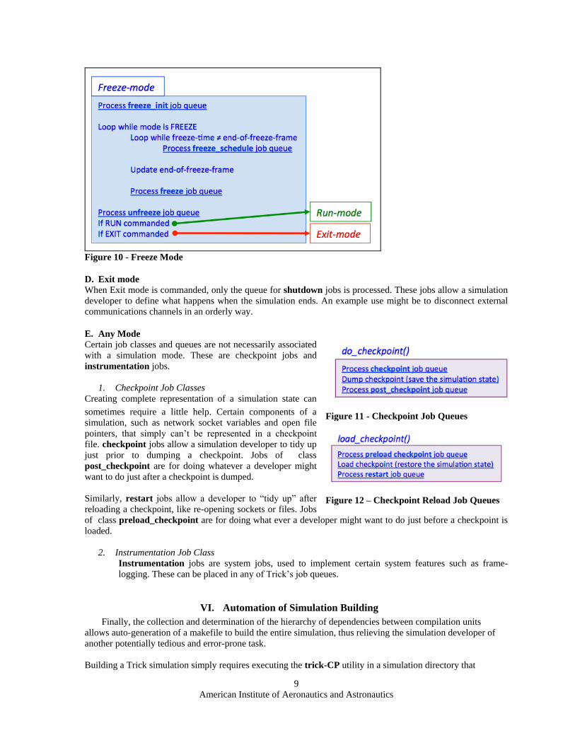
C. Freeze mode
When commanded, a simulation will enter freeze-mode, and simulation time will stop. For a real-time
simulation that is expected to regularly service hardware-in-the-loop, this might present a problem. Freeze-
mode job classes provide a means to define the behavior of a real-time simulation when time stops.
Trick provides four job classes for defining this behavior:
freeze_init jobs are executed on entering freeze-mode.
unfreeze jobs are executed on leaving freeze-mode.
freeze_schedule are scheduled similarly to scheduled jobs executed in run-mode.
freeze jobs are scheduled during freeze mode.
Page 9
American Institute of Aeronautics and Astronautics
9
Figure 10 - Freeze Mode
D. Exit mode
When Exit mode is commanded, only the queue for shutdown jobs is processed. These jobs allow a simulation
developer to define what happens when the simulation ends. An example use might be to disconnect external
communications channels in an orderly way.
E. Any Mode
Certain job classes and queues are not necessarily associated
with a simulation mode. These are checkpoint jobs and
instrumentation jobs.
1. Checkpoint Job Classes
Creating complete representation of a simulation state can
sometimes require a little help. Certain components of a
simulation, such as network socket variables and open file
pointers, that simply can’t be represented in a checkpoint
file. checkpoint jobs allow a simulation developer to tidy up
just prior to dumping a checkpoint. Jobs of class
post_checkpoint are for doing whatever a developer might
want to do just after a checkpoint is dumped.
Similarly, restart jobs allow a developer to “tidy up” after
reloading a checkpoint, like re-opening sockets or files. Jobs
of class preload_checkpoint are for doing what ever a developer might want to do just before a checkpoint is
loaded.
2. Instrumentation Job Class
Instrumentation jobs are system jobs, used to implement certain system features such as frame-
logging. These can be placed in any of Trick’s job queues.
VI. Automation of Simulation Building
Finally, the collection and determination of the hierarchy of dependencies between compilation units
allows auto-generation of a makefile to build the entire simulation, thus relieving the simulation developer of
another potentially tedious and error-prone task.
Building a Trick simulation simply requires executing the trick-CP utility in a simulation directory that
Figure 11 - Checkpoint Job Queues
Figure 12 – Checkpoint Reload Job Queues
Page 10
American Institute of Aeronautics and Astronautics
10
contains a well-formed S_define file.
From the S_define file, trick-CP:
Gathers variable definitions, such as instantiations of SimObjects that the simulation developer has
created
Gathers job specifications from each of the SimObjects specified in the S_define
Recursively gathers header file dependencies, starting with those in the S_define that start with
##include
Recursively gathers compilation unit dependencies, starting with those listed in the LIBRARY
DEPENDENCIES section of the S_define.
Generates Python interface code by processing all of the gathered header files using SWIG
Generates Memory Manager interface code by processing all of the gathered header files code using
ICG
Generates S_source.cpp from the S_define
Generates a makefile from the gathered compilation unit dependency information
Process the generated makefile to generate the simulation executable
The makefile compiles all of the user’s model source, the generated S_source.cpp and the auto-generated
interface code. It then links the compiled object code, any specified user-supplied libraries, and various pre-
compiled Trick libraries to produce the simulation executable.
The makefile generated by trick-CP includes a supplementary file named S_overrides.mk, if it exists in the
simulation directory. As its name suggests, the S_overrides.mk file allows one to over ride or supplement rules
and environment variables used by the makefile.
The S_overrides.mk file will often contain assignments to the following three environment variables:
TRICK_CFLAGS, TRICK_CXXFLAGS, and TRICK_USER_LINK_LIBS.
TRICK_CFLAGS, and TRICK_CXXFLAGS are flags that are passed to the the C and C++ compilers
respectively. They contain –I flags that specify the directory path to the header files used by the simulation.
TRICK_USER_LINK_LIBS contains –L and –l flags used by the linker. These specify the library
directory paths and the libraries that the simulation wishes to link into the final executable.
VII. Applications of Trick
Trick has a long history spanning nearly 25 years, providing a common simulation environment to all of
NASA's crewed vehicle programs since 1991.
In the early 1990s Trick was conceived and developed as a framework to support operational performance
evaluations of the Shuttle Remote Manipulator System (SRMS). The Canadian SRMS is six jointed robotic
manipulator attached to the side of the Space Shuttle cargo bay. The SRMS was used to deploy satellites and
other experiments from the cargo bay as well as retrieve free flyers such as the Hubble Space Telescope and
dock them into the cargo bay. The first Trick based SRMS simulations, called the Space Shuttle Payload
Deployment and Retrieval System (PDRS), included many of the core features still found in Trick today
including the job scheduler, input processor, and data recording capabilities. The PDRS simulation was used to
prototype and test SRMS flight software. The PDRS simulation performed dynamic loads analysis for
upcoming SRMS operations. The PDRS simulation performed ground and in-flight training for both astronauts
and ground controllers.
Page 11
American Institute of Aeronautics and Astronautics
11
Figure 13. Shuttle Remote Manipulator System with Androgynous Peripheral Attach System (APAS)
docking mechanism
Beginning in the mid 1990s and continuing through today, Mobile Servicing System (MSS) Trick
applications featuring the Canadian Space Station Remote Manipulator System (SSRMS) are used for a variety
of tasks including flight controller and crew training, robotic operations planning, and dynamic analysis. MSS
based simulations are the most prolific Trick applications and are used for engineering analysis, robotic
operation planning, and astronaut and flight grew training. These applications are deployed in multiple JSC
facilities including the Dynamic Skills Trainers (DST). DST installations combine the MSS simulation, a
simulated Robotics WorkStation (RWS), translational and rotational hand controllers, and 3D graphics into a
single desktop trainer. DSTs are designed to run on common desktop computer systems. The Robotics On-
Board Trainer (ROBoT) project adapts the DST to run on the laptops found onboard the ISS.
Figure 14. ROBoT installation on board the ISS
Project Morpheus is a terrestrial lander used as a vertical test bed platform for developing technology and
proving hardware and software systems for use in space exploration. Flight software developed for the lander
Page 12
American Institute of Aeronautics and Astronautics
12
uses NASA Goddard's Core Flight Software (CFS). Project Morpheus wraps the lander's Core Flight Software
(CFS) applications within a Trick simulation. This CFS embedded within a Trick simulation combination was
used throughout the development, test and operations software lifecycle by providing a single simulation
supporting multiple test configurations such as single-computer embedded simulation, distributed simulation,
hardware-in-the-loop simulation, and operator training.
Figure 15. MMSEV above rendering of the Martian moon Phobos.
For the next generation of space vehicles, the NASA Exploration Systems Simulations (NExSyS) project
uses Trick applications to perform mission scenario development, vehicle design and performance analyses, and
crew operations assessments for potential agency missions including exploration of asteroids and the Martian
system.
Figure 16. MMSEV above rendering of the Martian moon Phobos
Page 13
American Institute of Aeronautics and Astronautics
13
VIII. NASA Open Source: Trick on Github
Historically Trick was only available to other government agencies as a Government Purpose Release.
Trick could only be used for the project it was specifically released to. Beginning in 2007 Trick was
reclassified as a NASA General Public Release. As a General Public Release product this opened access to
corporations, universities, and individuals outside of NASA projects. However Trick was not completely open,
Trick was still only available with an approved application, and non-US citizens were forbidden to use Trick.
In February 2015 Trick transitioned from a General Public Release to an open source project under the NASA
Open Source Agreement 1.3. As of February 2015, The Trick Simulation Toolkit is licensed NASA Open
source, and is freely available for download at https://github.com/nasa/trick.
IX. Conclusions
The Trick simulation framework provides simulation developers with a development environment that frees
them of the need to reimplement commonly required simulation capabilities, and many other tedious and error
prone development activities. Trick enables simulation engineers to spend more of their time focused on the
unique aspects of their simulation problem. Providing a common architecture and toolset for building computer
simulations has additional benefits as well, such as code re-use. Well defined interfaces allow project specific
code to be routinely reused for other projects. Also, developers moving between projects aren’t burdened with
the need to re-learn a different architecture and toolset. These benefits are evident in the many training and
engineering simulations developed at the NASA Johnson Space Center.
X. References 1Penn, J. M., “Testability, Test Automation and Test Driven Development for the Trick Simulation Toolkit”, AIAA
Modeling and Simulation Technologies Conference, AIAA 2014-0640, 2014.
2Paddock, E. J., Lin A., Vetter, K., Crues E. Z, "Trick: A Simulation Development Toolkit", AIAA Modeling and
Simulation Technologies Conference, AIAA 2003-5809, 2003.
3Lin A.S., Vetter, K., Penn J.M., et al., “Trick User’s Guide”, URL: https://github.com/nasa/Trick/wiki/Users-Guide .