36
The Unified Modeling Language Student Workbook EVALUATION COPY Unauthorized reproduction or distribution is prohibited.

The UnifiedModeling Language
Student Workbook
EVALUATION COPY
Unauthorized reproduction or distribution is prohibited.

Page ii Rev 6.3.1 © 2013 ITCourseware, LLC
The Unified Modeling Language
The Unified Modeling Language
Lynwood Wilson
Published by ITCourseware, LLC., 7245 South Havana Street, Suite 100, Centennial, CO 80112
Contributing Authors: Jamie Romero, Rick Sussenbach, and Rob Seitz.
Editors: Danielle Hopkins and Jan Waleri
Editorial Assistant: Dana Howell
Special thanks to: Many instructors whose ideas and careful review have contributed to the qualityof this workbook, offering comments, suggestions, criticisms, and insights.
Copyright © 2013 by ITCourseware, LLC. All rights reserved. No part of this book may be reproducedor utilized in any form or by any means, electronic or mechanical, including photo-copying, recording, or byan information storage retrieval system, without permission in writing from the publisher. Inquiries should beaddressed to ITCourseware, LLC., 7245 South Havana Street, Suite 100, Centennial, Colorado, 80112.(303) 302-5280.
All brand names, product names, trademarks, and registered trademarks are the property of their respectiveowners.
EVALUATION COPY
Unauthorized reproduction or distribution is prohibited.

© 2013 ITCourseware, LLC Rev 6.3.1 Page iii
The Unified Modeling Language
Contents
Chapter 1 - Course Introduction ............................................................................................................. 7
Course Objectives ............................................................................................................................ 8The Unified Process .......................................................................................................................... 9Course Overview ........................................................................................................................... 10Using the Workbook ...................................................................................................................... 11Suggested References ..................................................................................................................... 12
Chapter 2 - Use Cases ......................................................................................................................... 15
Use Cases ...................................................................................................................................... 16Use Case Diagram Components ..................................................................................................... 18Use Case Diagram .......................................................................................................................... 20Actor Generalizations ...................................................................................................................... 22Include ........................................................................................................................................... 24Extend ............................................................................................................................................ 26Specialize ....................................................................................................................................... 28Other Systems ................................................................................................................................ 30Narrative ........................................................................................................................................ 32Template for Use Case Narrative .................................................................................................... 34Using Use Cases ............................................................................................................................ 36Labs ............................................................................................................................................... 38
Chapter 3 - Class Diagrams .................................................................................................................. 41
Class Diagrams ............................................................................................................................... 42Attributes ....................................................................................................................................... 44Attribute Properties ........................................................................................................................ 46Operations and Methods ................................................................................................................ 48Inheritance ...................................................................................................................................... 50Abstract Classes ............................................................................................................................. 52Interfaces ....................................................................................................................................... 54Interfaces with Ball and Socket Notation ......................................................................................... 56Visibility .......................................................................................................................................... 58Class Scope ................................................................................................................................... 60
EVALUATION COPY
Unauthorized reproduction or distribution is prohibited.

Page iv Rev 6.3.1 © 2013 ITCourseware, LLC
The Unified Modeling Language
Labs ............................................................................................................................................... 62
Chapter 4 - Class Diagrams and Relationships ....................................................................................... 65
Dependencies ................................................................................................................................. 66Associations ................................................................................................................................... 68Instance Creation ............................................................................................................................ 70Multiplicity ...................................................................................................................................... 72Qualified Associations ..................................................................................................................... 74Association Classes ........................................................................................................................ 76Composition and Aggregation ......................................................................................................... 78Labs ............................................................................................................................................... 80
Chapter 5 - Sequence Diagrams ........................................................................................................... 83
Sequence Diagrams ........................................................................................................................ 84Interaction Frames .......................................................................................................................... 86Decisions ........................................................................................................................................ 88Loops ............................................................................................................................................ 90Creating and Destroying Objects ..................................................................................................... 92Activation ....................................................................................................................................... 94Synchronous & Asynchronous ........................................................................................................ 96Evaluating Sequence Diagrams ........................................................................................................ 98Using Sequence Diagrams ............................................................................................................. 100Labs ............................................................................................................................................. 102
Chapter 6 - Communication Diagrams ................................................................................................. 105
Communication Diagrams ............................................................................................................. 106Communication and Class Diagrams .............................................................................................. 108Evaluating Communication Diagrams ............................................................................................. 110Using Communication Diagrams .................................................................................................... 112Labs ............................................................................................................................................. 114
Chapter 7 - State Machine Diagrams .................................................................................................. 117
What is State? .............................................................................................................................. 118State Notation .............................................................................................................................. 120Transitions and Guards .................................................................................................................. 122Registers and Actions .................................................................................................................... 124More Actions ............................................................................................................................... 126
EVALUATION COPY
Unauthorized reproduction or distribution is prohibited.

© 2013 ITCourseware, LLC Rev 6.3.1 Page v
The Unified Modeling Language
Internal Transitions ........................................................................................................................ 128Superstates and Substates ............................................................................................................. 130Concurrent States ......................................................................................................................... 132Using State Machines ................................................................................................................... 134Implementation ............................................................................................................................. 136Labs ............................................................................................................................................. 138
Chapter 8 - Activity Diagrams ............................................................................................................. 141
Activity Notation .......................................................................................................................... 142Decisions and Merges ................................................................................................................... 144Forks and Joins ............................................................................................................................ 146Drilling Down ............................................................................................................................... 148Iteration ........................................................................................................................................ 150Partitions ...................................................................................................................................... 152Signals .......................................................................................................................................... 154Parameters and Pins ..................................................................................................................... 156Expansion Regions ........................................................................................................................ 158Using Activity Diagrams ................................................................................................................ 160Labs ............................................................................................................................................. 162
Chapter 9 - Supplemental UML Diagrams ........................................................................................... 165
Modeling Groups of Elements - Package Diagrams ....................................................................... 166Visibility and Importing .................................................................................................................. 168Structural Diagrams ...................................................................................................................... 170Components and Interfaces ........................................................................................................... 172Deployment Diagram .................................................................................................................... 174Composite Structure Diagrams ...................................................................................................... 176Timing Diagrams ........................................................................................................................... 178Interaction Overview Diagrams ..................................................................................................... 180Labs ............................................................................................................................................. 182
Appendix A - UML Syntax ................................................................................................................. 185
Solutions ............................................................................................................................................ 193
Index .................................................................................................................................................. 207
EVALUATION COPY
Unauthorized reproduction or distribution is prohibited.

Page vi Rev 6.3.1 © 2013 ITCourseware, LLC
The Unified Modeling Language
EVALUATION COPY
Unauthorized reproduction or distribution is prohibited.

Course Introduction
© 2013 ITCourseware, LLC Rev 6.3.1 Page 7
Chapter 1
Chapter 1 - Course IntroductionEVALUATION COPY
Unauthorized reproduction or distribution is prohibited.

THe Unified Modeling Language
Page 8 Rev 6.3.1 © 2013 ITCourseware, LLC
Use modeling in analysis and design, particularly in visual modeling.
Use the Unified Modeling Language to create visual models of businessproblems and software solutions.
Create models to show relationships between classes.
Create models to portray activities performed by objects.
Create models to portray complex algorithms.
Create models to show object state.
Create models to portray object creation.
Course Objectives
EVALUATION COPY
Unauthorized reproduction or distribution is prohibited.
Course Introduction
© 2013 ITCourseware, LLC Rev 6.3.1 Page 9
Chapter 1
The Unified ProcessThis workbook references the Unified Process.
The Unified Process is an iterative process, made up of four major phases:
The first phase is the Inception Phase, usually used to define what theproject will be and create a business case for the project.
The second phase is the Elaboration Phase. It is used to perform analysis,prototyping, define the initial architecture, and create a more in-depthbusiness case.
The Construction Phase is the third phase. This phase contains arepeating cycle of analysis design code and tests, which produces anincrement of functionality.
The final phase is the Transition Phase, in which you train the users anddeliver the final working product.
In each of these phases, diagrams can be created with different perspectives:
The first perspective is the Domain Perspective, in which diagrams depicthow the current system works.
The second perspective is the Specification and RequirementsPerspective, in which the diagrams depict what the new system will do.
The last perspective is the Design Perspective. This perspective tells howthe new system will perform the specification and requirements.
EVALUATION COPY
Unauthorized reproduction or distribution is prohibited.

THe Unified Modeling Language
Page 10 Rev 6.3.1 © 2013 ITCourseware, LLC
Audience: Programmers, analysts and software designers.
Prerequisites: Experience with objects and object-oriented programming.Experience with analysis and design would be helpful.
This course is based on UML Version 2.0, and occasionally mentions featuresfrom previous versions.
Course Overview
EVALUATION COPY
Unauthorized reproduction or distribution is prohibited.

Course Introduction
© 2013 ITCourseware, LLC Rev 6.3.1 Page 11
Chapter 1
Using the Workbook
Chapter 2 Servlet Basics
© 2002 ITCourseware, LLC Rev 2.0.0 Page 17
Add an init() method to your Today servlet that initializes a bornOn date, then print the bornOn date
along with the current date:
Today.java
...
public class Today extends GenericServlet {
private Date bornOn;
public void service(ServletRequest request,
ServletResponse response) throws ServletException, IOException
{
...
// Write the document
out.println("This servlet was born on " + bornOn.toString());
out.println("It is now " + today.toString());
}
public void init() {
bornOn = new Date();
}
}
Hands On:
The init() method is
called when the servlet is
loaded into the container.
This workbook design is based on a page-pair, consisting of a Topic page and a Support page. When youlay the workbook open flat, the Topic page is on the left and the Support page is on the right. The Topicpage contains the points to be discussed in class. The Support page has code examples, diagrams, screenshots and additional information. Hands On sections provide opportunities for practical application of keyconcepts. Try It and Investigate sections help direct individual discovery.
In addition, there is an index for quick look-up. Printed lab solutions are in the back of the book as well ason-line if you need a little help.
Java Servlets
Page 16 Rev 2.0.0 © 2002 ITCourseware, LLC
� The servlet container controls the life cycle of the servlet.
� When the first request is received, the container loads the servlet class
and calls the init() method.
� For every request, the container uses a separate thread to call
the service() method.
� When the servlet is unloaded, the container calls the destroy()
method.
� As with Java’s finalize() method, don’t count on this being
called.
� Override one of the init() methods for one-time initializations, instead of
using a constructor.
� The simplest form takes no parameters.
public void init() {...}
� If you need to know container-specific configuration information, use
the other version.
public void init(ServletConfig config) {...
� Whenever you use the ServletConfig approach, always call the
superclass method, which performs additional initializations.
super.init(config);
The Servlet Life Cycle
The Topic page providesthe main topics for
classroom discussion.
The Support page hasadditional information,
examples and suggestions.
Code examples are in afixed font and shaded. Theon-line file name is listedabove the shaded area.
Screen shots showexamples of what youshould see in class.
Topics are organized intofirst ( ), second ( ) and
third ( ) level points.
Pages are numberedsequentially throughout
the book, making lookupeasy.
Callout boxes point outimportant parts of the
example code.
EVALUATION COPY
Unauthorized reproduction or distribution is prohibited.

THe Unified Modeling Language
Page 12 Rev 6.3.1 © 2013 ITCourseware, LLC
Bellin, David and Susan Simone. 1997. The CRC Card Book. Addison-Wesley, Reading, MA. ISBN0201895358.
Booch, Grady, James Rumbaugh and Ivar Jacobson. 2005. The Unified Modeling Language UserGuide, Second Edition. Addison-Wesley, Reading, MA. ISBN 0321267974.
Cockburn, Alistair. 2000. Writing Effective Use Cases. Addison-Wesley, Reading, MA. ISBN0201702258.
Fowler, Martin, et al. 1999. Refactoring: Improving the Design of Existing Code. Addison-Wesley, Reading, MA. ISBN 0201485672.
Fowler, Martin. 2003. UML Distilled: A Brief Guide to the Standard Object Modeling Language,Third Edition. Addison-Wesley, Reading, MA. ISBN 0321193687.
Gamma, Erich, et al. 1995. Design Patterns: Elements of Reusable Object-Oriented Software.Addison-Wesley, Reading, MA. ISBN 0201633612.
Jacobson, Ivar, Grady Booch and James Rumbaugh. 1999. The Unified Software DevelopmentProcess. Addison-Wesley, Reading, MA. ISBN 0201571692.
Kruchten, Philippe. 2003. The Rational Unified Process: An Introduction, Third Edition. Addison-Wesley, Reading, MA. ISBN 0321197704.
Larman, Craig. 2004. Applying UML and Patterns : An Introduction to Object-Oriented Analysisand Design and Iterative Development, Third Edition. Prentice-Hall, Englewood Cliffs, NJ.ISBN 0131489062.
Page-Jones, Meilir. 1999. Fundamentals of Object-Oriented Design in UML. Addison-Wesley,Reading, MA. ISBN 020169946X.
Pilone, Dan and Neil Pitman. 2005. UML 2.0 in a Nutshell. O'Reilly & Associates, Sebastopol, CA.ISBN 0596007957.
Rumbaugh, James, Ivar Jacobson and Grady Booch. 2004. The Unified Modeling LanguageReference Manual, Second Edition. Addison-Wesley, Reading, MA. ISBN 0321245628.
http://alistair.cockburn.us/index.php/Resources_for_writing_use_caseshttp://www.sparxsystems.com/uml-tutorial.htmlhttp://www.uml.org
Suggested References
EVALUATION COPY
Unauthorized reproduction or distribution is prohibited.

Course Introduction
© 2013 ITCourseware, LLC Rev 6.3.1 Page 13
Chapter 1
EVALUATION COPY
Unauthorized reproduction or distribution is prohibited.

THe Unified Modeling Language
Page 14 Rev 6.3.1 © 2013 ITCourseware, LLC
EVALUATION COPY
Unauthorized reproduction or distribution is prohibited.

Chapter 3 Class Diagrams
© 2013 ITCourseware, LLC Rev 6.3.1 Page 41
Chapter 3 - Class Diagrams
Objectives
Describe UML syntax for class diagrams.
Describe the format of class attributes andany constraints applied to those attributes.
Show the notation for inheritance ofsuperclasses.
Show the various notations for interfaceimplementation.
Use class diagrams to depict abstractclasses.
Diagram class methods and attributes.
EVALUATION COPY
Unauthorized reproduction or distribution is prohibited.

The Unified Modeling Language
Page 42 Rev 6.3.1 © 2013 ITCourseware, LLC
A class is like a template for creating objects; it is the definition, description, orblueprint of the object.
The class tells what attributes and methods each instance of that class willhave.
The class also describes the public interface through which other objectscan interact with this class.
The class is where the code for the methods is held.
By convention, class names are capitalized.
Here is the UML symbol for the Date class.
Attributes (fields) and methods (member functions) can also be added to theclass diagram. The attributes go in a second box, under the class name. Themethods go in the third box.
Class Diagrams
Date
Date
yearmonthday
getYear()
setYear()
...
addDays()
addMonths()
...
EVALUATION COPY
Unauthorized reproduction or distribution is prohibited.

Chapter 3 Class Diagrams
© 2013 ITCourseware, LLC Rev 6.3.1 Page 43
You can organize your attributes and methods by adding stereotypes in your diagram. Within thestereotype add a descriptive name to identify a grouping.
After the third box other boxes can be added to include additional class information. A commonpossibility would be the class responsibilities that were determined during analysis and design.Another candidate would be a list of exceptions that might be generated by the class.
Student
name:String
gpa:float
balance:float
phone:String
«constructors»
Student()
Student(name:String, gpa:float)
«mutators»
setName()
setGPA()
«accessors»
getName()
getGPA()
Student
Exceptions
NegativeBalanceException
DuplicateNameException
EVALUATION COPY
Unauthorized reproduction or distribution is prohibited.
The Unified Modeling Language
Page 44 Rev 6.3.1 © 2013 ITCourseware, LLC
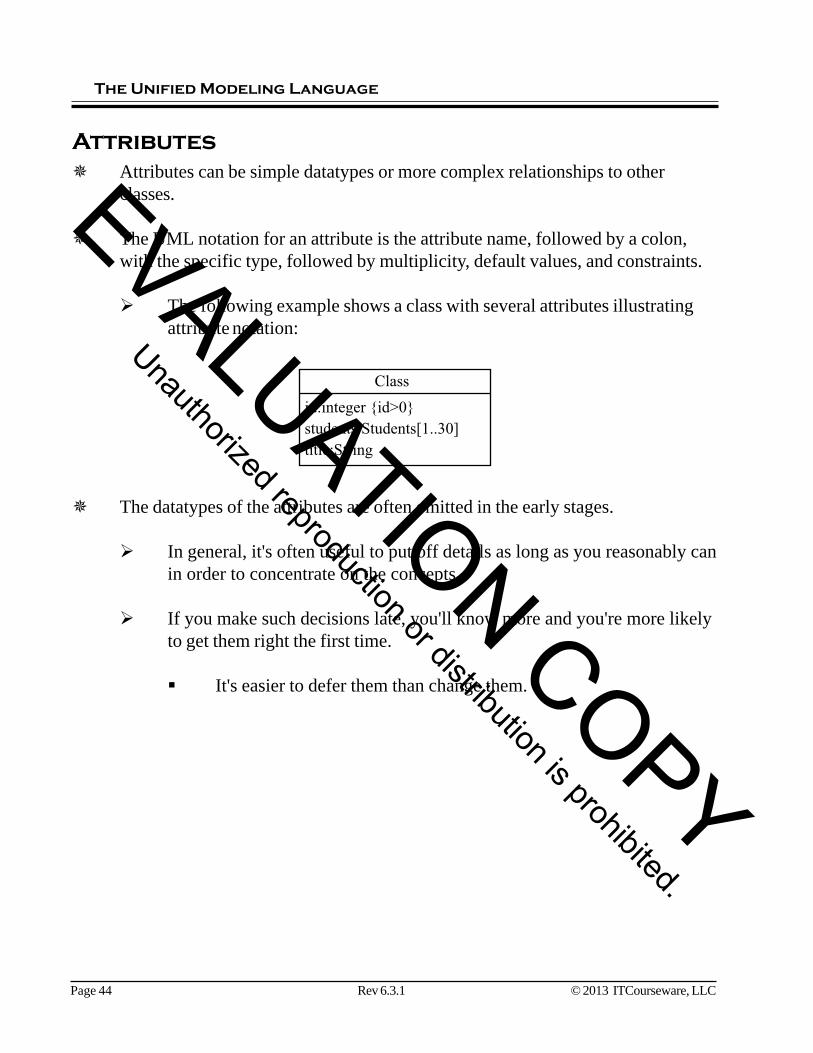
Attributes can be simple datatypes or more complex relationships to otherclasses.
The UML notation for an attribute is the attribute name, followed by a colon,with the specific type, followed by multiplicity, default values, and constraints.
The following example shows a class with several attributes illustratingattribute notation:
The datatypes of the attributes are often omitted in the early stages.
In general, it's often useful to put off details as long as you reasonably canin order to concentrate on the concepts.
If you make such decisions late, you'll know more and you're more likelyto get them right the first time.
It's easier to defer them than change them.
Attributes
Class
id:integer {id>0}
students:Students[1..30]
title:String
EVALUATION COPY
Unauthorized reproduction or distribution is prohibited.

Chapter 3 Class Diagrams
© 2013 ITCourseware, LLC Rev 6.3.1 Page 45
The member data items (attributes) go in the second box. We usually assume in the early stages that alldata is hidden in the object and cannot be accessed from outside.
There are often rules (constraints) to govern the values of the attributes. There are only twelvemonths. Each has a maximum number of days. There are leap years. All these rules are written intothe code that is part of the object so that the data is always maintained in a legal state and the outsidecode never has to worry about it.
Such rules can be represented in a UML model as a text in a box with its corner turned down or as aconstraint in curly braces. The box above specifies the legal values for the attribute month. Theconstraint in the curly braces specifies the legal values for day.
You may also specify constraints and relationships between attributes in a separate text file associatedwith the object. The constraints on a Date are too complex to put in the above diagram. You'd createa separate text document.
An outside function can add a day to a date, and rest assured that the Date object will handlewrapping around to the next month or next year, as necessary.
Date
day {1-31}
month
year
Months are:January,February,. . .
EVALUATION COPY
Unauthorized reproduction or distribution is prohibited.

The Unified Modeling Language
Page 46 Rev 6.3.1 © 2013 ITCourseware, LLC
Attribute PropertiesAttributes can have several properties enclosed in curly braces after the attributemultiplicity. Some of the properties UML has specified include:
ordered — You use this to say that an attribute is sorted if the multiplicityof the attribute is greater than one.
unique — You use this to say that attribute values are unique if themultiplicity of the attribute is greater than one.
readonly — The attribute may not be modified once given an initialvalue.
The following Invoice class has an array of item integers that will be stored insorted order and does not allow duplicates.
Invoice
invNo:integer
date:Date
items:integer[1..20] {unique, ordered}
balance:float {balance>=0}
EVALUATION COPY
Unauthorized reproduction or distribution is prohibited.

Chapter 3 Class Diagrams
© 2013 ITCourseware, LLC Rev 6.3.1 Page 47
EVALUATION COPY
Unauthorized reproduction or distribution is prohibited.

The Unified Modeling Language
Page 48 Rev 6.3.1 © 2013 ITCourseware, LLC
Operations and MethodsA method is a function that belongs to an object.
These are sometimes called member functions, because they are membersof the class.
An operation is similar to a method, but at a more abstract level.
Methods are concrete things: functions with code (or at least algorithms),arguments lists, and return types.
Operations are abstract — just a name that carries a general idea of what itwill do, with or without the argument list and return type, but alwayslacking code.
Usually there is a one-to-one relationship between the operations of aclass and its methods that you define later as your model becomes moreconcrete. Sometimes an operation will yield several methods that do thesame thing, but differ in argument list, datatypes, etc.
A class can have methods that do not descend directly from an operation.Often these are private, for internal use only.
Methods or operations go in the third box.
The UML specification for a method is the method name, followed by theparameter list in parentheses, and then a colon with the return type of themethod.
The parameter listing will have the same specification format as attributes.
Methods can have pre-condition and post-condition constraints enclosed incurly braces specifying when the method can be called and what the outcomeshould be.
EVALUATION COPY
Unauthorized reproduction or distribution is prohibited.

Chapter 3 Class Diagrams
© 2013 ITCourseware, LLC Rev 6.3.1 Page 49
Invoice
invNo:integer
date:Date
items:integer[1..20] {unique, ordered}
balance:float {balance>=0}
sendItems():boolean {precondition:balance=0}
...
Date
year:integermonth:integerday:integer
getYear():integersetYear(integer)...addDays(integer)addMonths(integer)addYears(integer)...cleanup()
same for subtraction
same for monthand day
EVALUATION COPY
Unauthorized reproduction or distribution is prohibited.

The Unified Modeling Language
Page 50 Rev 6.3.1 © 2013 ITCourseware, LLC
InheritanceInheritance allows you to create a new class that contains all of the attributesand methods of an existing class, and then add to them. The new class isactually an instance of the parent class.
The class you inherit from is often called the superclass, and the inheritedclass is the subclass.
The subclass may add new attributes or methods, but it always has all ofthe attributes and methods of the superclass.
The subclass may override one or more of the methods of the superclassby providing different implementations (code) for them.
You show inheritance by drawing a solid line with a closed arrow fromthe child class to the parent class.
Person
Student Teacher
EVALUATION COPY
Unauthorized reproduction or distribution is prohibited.

Chapter 3 Class Diagrams
© 2013 ITCourseware, LLC Rev 6.3.1 Page 51
Other words for inheritance relationships:
Superclass — Subclass (This is traditional OO terminology)Generalization — SpecializationBase class — Derived class (This is C++ terminology)Parent class — Child classAncestor class — Descendent class
Person
Student Teacher
nameaddressphonedateOfBirthsetName()getName(). . .
stuIdgpaclassStanding
getId()getName()
empNumdeptsalary
raiseSalary()
EVALUATION COPY
Unauthorized reproduction or distribution is prohibited.

The Unified Modeling Language
Page 52 Rev 6.3.1 © 2013 ITCourseware, LLC
Abstract ClassesAn abstract class is one that cannot be instantiated; it exists for the sake of aninheritance hierarchy.
In UML, show that a class is abstract by italicizing its name.
You can also use a stereotype.
Abstract classes often contain one or more method declarations, which have nocode.
Note that draw() above is in italics to indicate that it has noimplementation (code).
The Graphic class could not draw itself even if it had code. It doesn'tknow what shape it is.
Abstract classes are intended to be used by subclasses that provideimplementations for the code-less methods.
If a class inherits from an abstract base class, but does not provide codefor all of the methods that have no code in the abstract class, the subclasswill also be abstract.
Any class that has methods without code, or that inherits methods withoutcode but does not provide their code, is abstract and cannot beinstantiated.
Graphic
locationcolor
draw()
Graphic
«abstract»
EVALUATION COPY
Unauthorized reproduction or distribution is prohibited.

Chapter 3 Class Diagrams
© 2013 ITCourseware, LLC Rev 6.3.1 Page 53
The following diagram shows the abstract class Graphic with an abstract method draw(). Square, Circle,and Triangle inherit Graphic and thus must implement the abstract draw() method, or be abstract also.
Circle
draw()getColor()
draw()
Square
draw()
Triangle
draw()
Graphic
locationcolor
EVALUATION COPY
Unauthorized reproduction or distribution is prohibited.

The Unified Modeling Language
Page 54 Rev 6.3.1 © 2013 ITCourseware, LLC
InterfacesAn interface is like a class that has only a public interface and no private part.
An interface has no attributes (except possibly constants).An interface has public operations (method declarations), but no code forthem.Interfaces are naturally abstract. They cannot be instantiated.
Indicate an interface with a stereotype.
We say Circle implements Graphic even though it looks like inheritance (notethat the line is broken instead of solid).
This means Circle and Square inherit the method declarations ofGraphic.Circle and Square must provide code for Graphic's draw operation orthey become abstract and cannot be instantiated.
In Java and C#, interfaces are part of the language.
Java and C# do not allow multiple inheritance, but a class may implementmultiple interfaces, which gives some of the advantages of multipleinheritance, but few of the complications.
Interfaces are not part of the C++ language, but you can get the same effect bycreating abstract classes with no code or attributes.
Use a stereotype to label them «interface».
«interface»
Graphic
draw()
Circle Square
EVALUATION COPY
Unauthorized reproduction or distribution is prohibited.

Chapter 3 Class Diagrams
© 2013 ITCourseware, LLC Rev 6.3.1 Page 55
A class may implement several interfaces to get much of the effect of multiple inheritance. Since thereare no (variable) attributes in an interface, the problems we mentioned earlier do not occur.
Don't be afraid of multiple inheritance in domain and specification models, if you find it useful. Indesign, you will probably have to stick closer to what your implementation language can do.
Note that polymorphism works with classes that implement the same interface just as it does withclasses that inherit from the same ancestor. Of course, the only methods that can be usedpolymorphically are those from the interface.
There may well be more structure to an interface than just a set of operations. For example, a certainoperation might need to be executed before another operation is usable for a particular purpose. In acomplicated case, an interface may have associated with it a state machine or a use case model.
It's impossible to create a modeling language (or any other kind of language) that will cover allpossible cases. The stereotype is one of the ways we can extend the UML to communicate things thatthe creators did not anticipate. We can use it to create new specialized elements from existing generalones.
If you can't find the «guillemets» on your keyboard, you can use double angle brackets for<<stereotype>>.
EVALUATION COPY
Unauthorized reproduction or distribution is prohibited.

The Unified Modeling Language
Page 56 Rev 6.3.1 © 2013 ITCourseware, LLC
Interfaces with Ball and Socket NotationThe implementation of an interface can also be expressed using a ball notation.
The interface is expressed as a ball with a line to the class that implementsit. The name of the interface is written below the ball.
The following class diagram shows that Circle implements the Graphicinterface.
Some classes are dependent on other classes that implement a particularinterface.
Classes that are dependent on a particular interface implementation areexpressed using a socket with the name of the interface below the socket.
The Picture class in the following diagram is dependent on other objectsthat implement the Graphic interface.
Put them together and you can see that the Picture class is using the Circle classthrough the Graphic interface.
CircleGraphic
PictureGraphic
Picture
Graphic
Circle
EVALUATION COPY
Unauthorized reproduction or distribution is prohibited.

Chapter 3 Class Diagrams
© 2013 ITCourseware, LLC Rev 6.3.1 Page 57
The following diagram depicts an IAccount interface that is implemented by several classes. TheBank class uses the IAccount interface; thus all the other classes can work with the Bank class.
«interface»
IAccount
deposit(Float)
withdraw(Float)
getBalance():Float
Bank
IAccount
Savings
IAccount
Checking
IAccount
401K
IAccount
CD
IAccount
EVALUATION COPY
Unauthorized reproduction or distribution is prohibited.

The Unified Modeling Language
Page 58 Rev 6.3.1 © 2013 ITCourseware, LLC
VisibilityUML specifies four different types of visibility modifiers: public, private,protected, and package.
Public data or methods are accessible by the methods of any other class.
A public modifier is indicated with a + at the left of the line.
Private data or methods are accessible only by the methods of the class in whichit was declared.
A private modifier is indicated with a - at the left of the line.
Protected data or methods in the superclass are accessible by the methods of itssubclasses.
The exact meaning of "protected" varies between languages.
A protected modifier is indicated with a # at the left of the line.
Package visibility means that it is accessible to any code in the same package,including code in packages contained within this one.
A package modifier is indicated with a tilde (~).
EVALUATION COPY
Unauthorized reproduction or distribution is prohibited.

Chapter 3 Class Diagrams
© 2013 ITCourseware, LLC Rev 6.3.1 Page 59
Date-year:integer-month:integer-day:integer
+getYear():integer+setYear(integer). . .+addDays(integer)+addMonths(integer)+addYears(integer). . .-cleanup()
same for monthand day
same for subtraction
EVALUATION COPY
Unauthorized reproduction or distribution is prohibited.

The Unified Modeling Language
Page 60 Rev 6.3.1 © 2013 ITCourseware, LLC
Class ScopeAn attribute of a class may have class scope.
This means there is one copy of the attribute, regardless of how manyinstances of the class are created.
The class scope attribute exists even if there are no instances of the class.
All of the instances of the class have access to this single copy of the classscope attribute.
Its visibility may be public, private, protected, or package. Generally, anyclass scope attributes are also constants.
The UML syntax for class scope is to underline the attribute name.
A method may also have class scope.
A class scope method may be called on the class in a situation where thereare no instances of the class or the calling code does not have access toone.
Such a method may access class scope data, but not object scopeattributes. Since it may be called without an object, how would it knowwhich object's attribute to use?
Class scope methods may also be public, private, protected, or package.
You specify whether an attribute or a method has class scope by underlining it inthe class diagram.
EVALUATION COPY
Unauthorized reproduction or distribution is prohibited.

Chapter 3 Class Diagrams
© 2013 ITCourseware, LLC Rev 6.3.1 Page 61
The following student class has a static field called nextId. This field exists in the class and a studentobject does not need to be instantiated to access this field. You also have access to a static methodcalled getNextId() to get the value of nextId. This allows nextId to be encapsulated inside the class.
Student
getNextId()
getId()
nextId = 1
id
EVALUATION COPY
Unauthorized reproduction or distribution is prohibited.
The Unified Modeling Language
Page 62 Rev 6.3.1 © 2013 ITCourseware, LLC
Create a class diagram to depict an account at a bank. Include any fields and methods thatmight be needed to represent any account at a bank.
Create a class diagram for checking and savings account classes. Use inheritance to reusewhat you developed in the previous lab.
Create a class called InterestChecking. Again, use inheritance to reuse what you developedin the previous lab.
Add visibility modifiers to your class diagrams.
Labs
EVALUATION COPY
Unauthorized reproduction or distribution is prohibited.


