76
The Unique, Centrifugally Cast, Fiberglass-Reinforced, Polymer Mortar Pipe Facts & Specifications The Complete HOBAS Guide
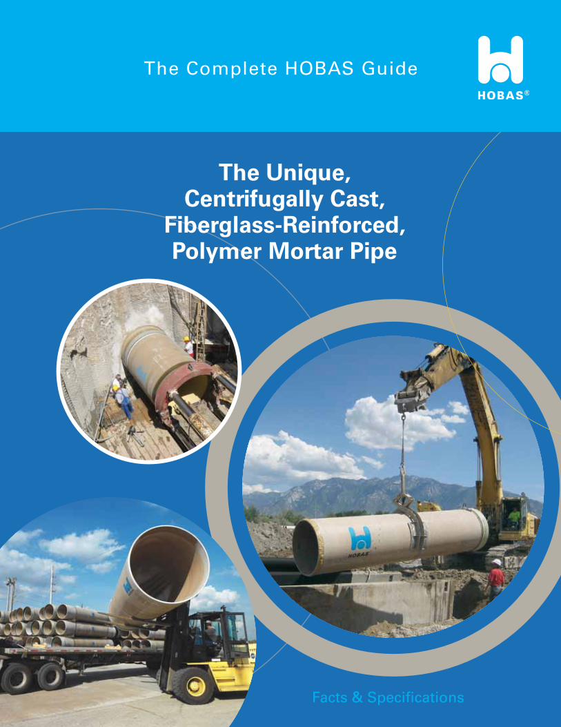
The Unique, Centrifugally Cast,
Fiberglass-Reinforced, Polymer Mortar Pipe
Facts & Specifications
The Complete HOBAS Guide
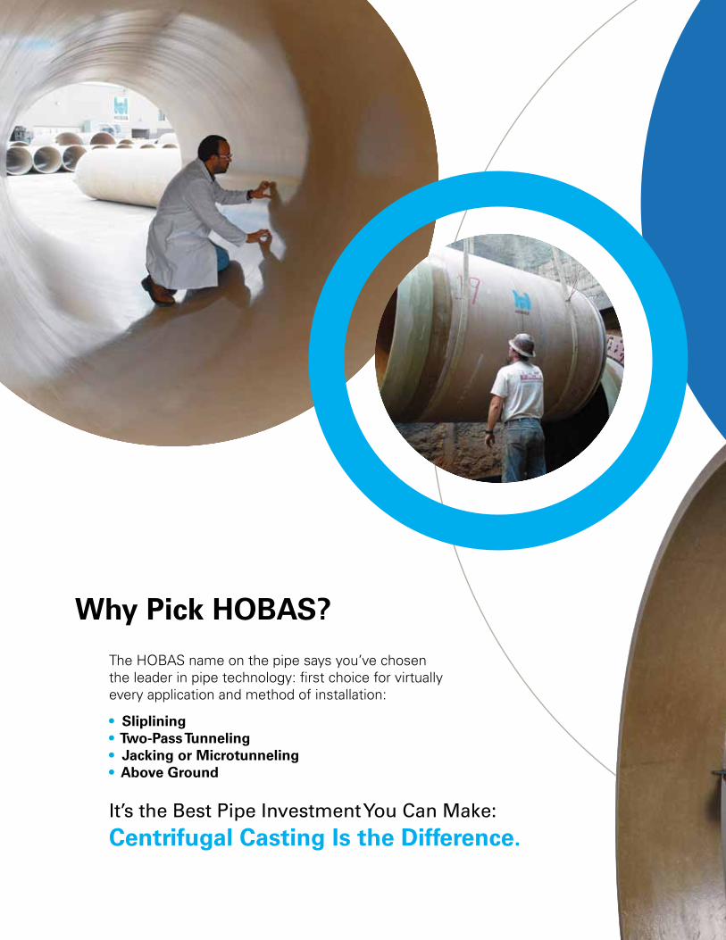
Why Pick HOBAS?
The HOBAS name on the pipe says you’ve chosen the leader in pipe technology: first choice for virtually every application and method of installation:
• Sliplining • Two-Pass Tunneling • Jacking or Microtunneling • Above Ground
It’s the Best Pipe Investment You Can Make: Centrifugal Casting Is the Difference.
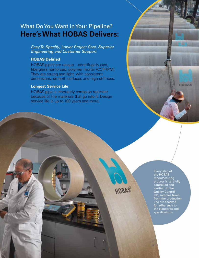
What Do You Want in Your Pipeline? Here’s What HOBAS Delivers:
Easy To Specify, Lower Project Cost, Superior Engineering and Customer Support
HOBAS DefinedHOBAS pipes are unique – centrifugally cast, fiberglass reinforced, polymer mortar (CCFRPM). They are strong and light with consistent dimensions, smooth surfaces and high stiffness.
Longest Service LifeHOBAS pipe is inherently corrosion resistant because of the materials that go into it. Design service life is up to 100 years and more.
Every step of the HOBAS manufacturing process is carefully controlled and verified. In the Quality Control lab, samples taken from the production line are checked for adherence to the standards and specifications.
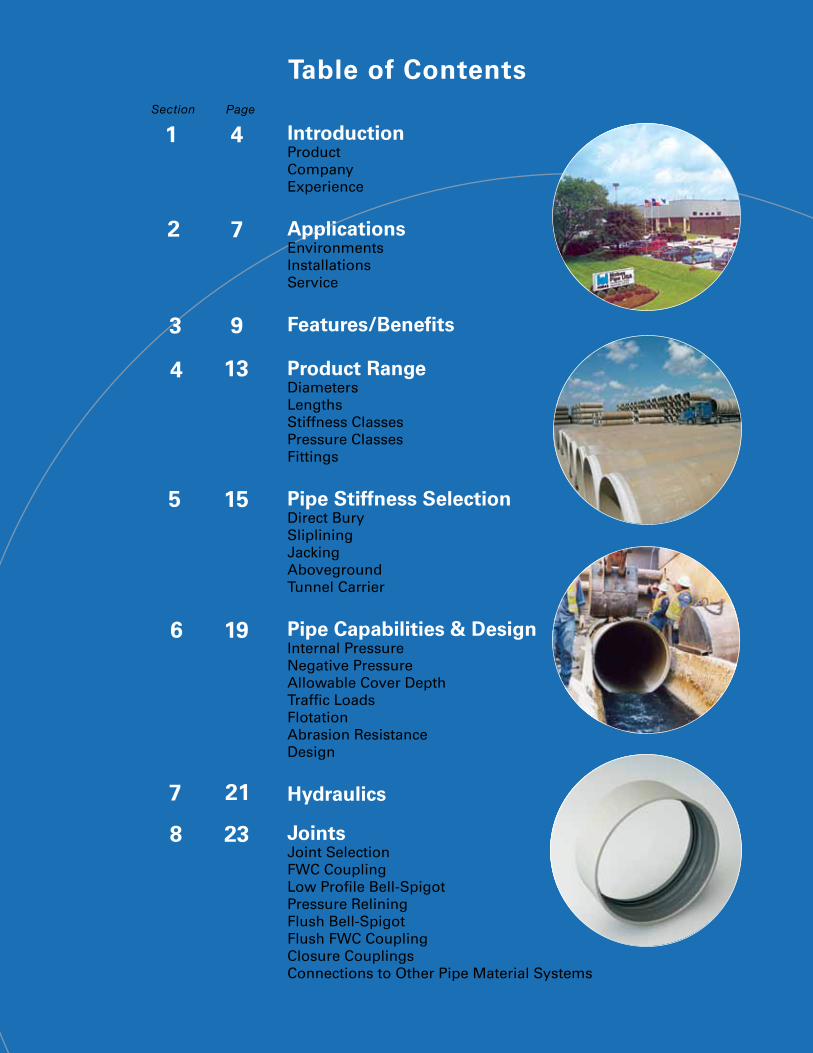
Table of Contents
2
3
4
5
6
4
7
9
13
15
19
7 21
8 23
1Section Page
IntroductionProductCompanyExperience
ApplicationsEnvironmentsInstallationsService
Features/Benefits
Product RangeDiametersLengthsStiffness ClassesPressure ClassesFittings
Pipe Stiffness SelectionDirect BurySlipliningJackingAbovegroundTunnel Carrier
Pipe Capabilities & DesignInternal PressureNegative PressureAllowable Cover DepthTraffic LoadsFlotationAbrasion ResistanceDesign
Hydraulics
JointsJoint SelectionFWC CouplingLow Profile Bell-SpigotPressure ReliningFlush Bell-SpigotFlush FWC CouplingClosure CouplingsConnections to Other Pipe Material Systems
9
A
B
C
D
E
F
G
10
11
12
13
14
29
49
55
57
59
60
64
70
31
33
35
37
39
Fittings
ManholesHOBAS Tee Base SystemConnecting HOBAS Pipe to Concrete Manhole Systems
Pipe Manufacturing Process
Quality Control
Standards
InstallationA - Direct BuryB - SlipliningC - JackingD - AbovegroundE - Tunnel Carrier
AppendixGuide SpecificationsNon-Pressure Service Pressure Service Direct Bury PipesSliplining Pipes Jacking PipesAboveground PipesTunnel Carrier Pipes
Pipe Dimensions & Weights
Joint Dimensions & Weights
Pipe Material Properties and Characteristics
Fitting Dimensions
Corrosion Resistance Guide
Deflected Pipe Minimum Inside Diameters
Section Page
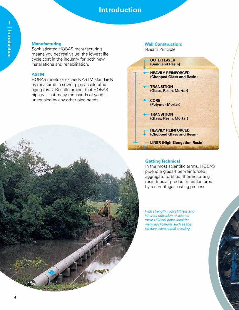
High strength, high stiffness and inherent corrosion resistance make HOBAS pipes ideal for many applications such as this sanitary sewer aerial crossing.
Introduction
1
Intro
du
ction
ManufacturingSophisticated HOBAS manufacturing means you get real value, the lowest life cycle cost in the industry for both new installations and rehabilitation.
ASTMHOBAS meets or exceeds ASTM standards as measured in sewer pipe accelerated aging tests. Results project that HOBAS pipe will last many thousands of years – unequaled by any other pipe needs.
Getting TechnicalIn the most scientific terms, HOBAS pipe is a glass-fiber-reinforced, aggregate-fortified, thermosetting-resin tubular product manufactured by a centrifugal casting process.
Wall Construction: I-Beam Principle
OUTER LAYER (Sand and Resin)
HEAVILY REINFORCED(Chopped Glass and Resin)
TRANSITION (Glass, Resin, Mortar)
CORE (Polymer Mortar)
TRANSITION (Glass, Resin, Mortar)
HEAVILY REINFORCED (Chopped Glass and Resin)
LINER (High Elongation Resin)
4
OUTER LAYER (Sand and Resin)
HEAVILY REINFORCED(Chopped Glass and Resin)
TRANSITION (Glass, Resin, Mortar)
CORE (Polymer Mortar)
TRANSITION (Glass, Resin, Mortar)
HEAVILY REINFORCED (Chopped Glass and Resin)
LINER (High Elongation Resin)
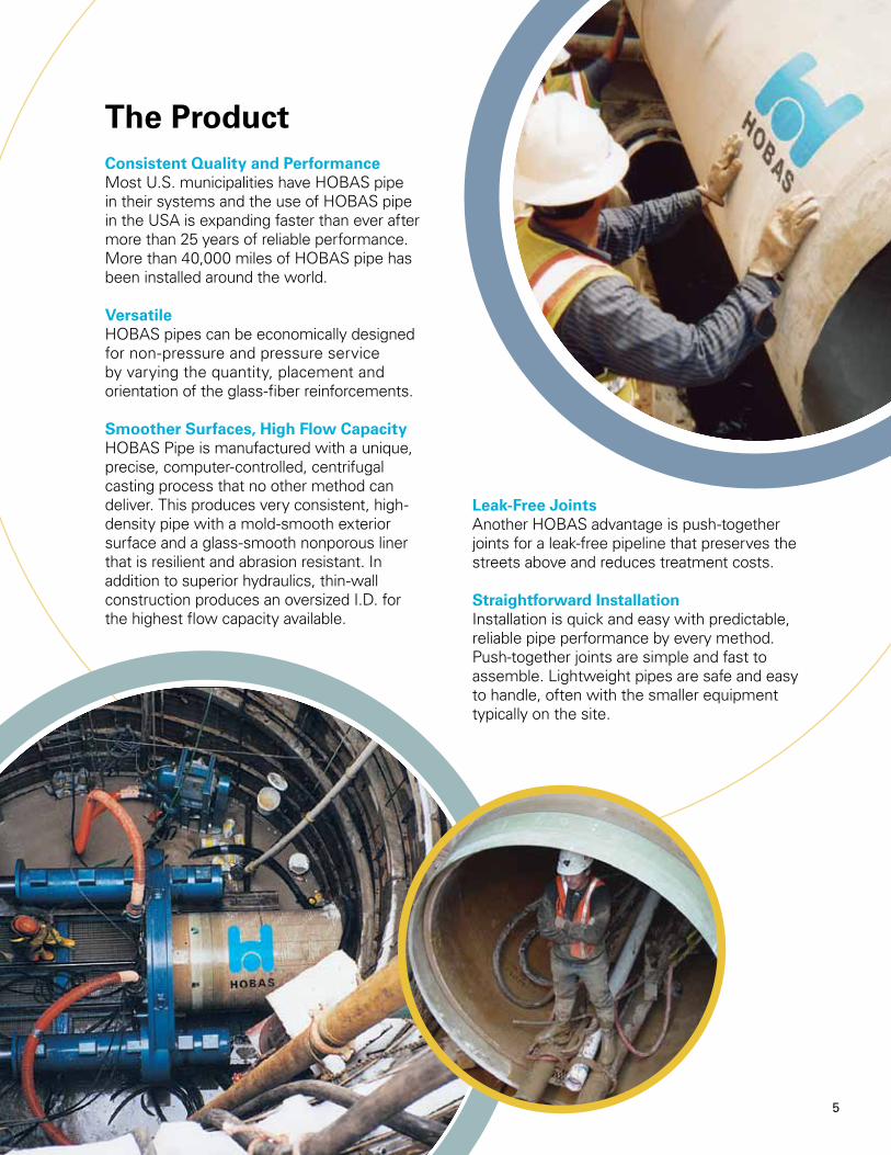
Consistent Quality and Performance Most U.S. municipalities have HOBAS pipe in their systems and the use of HOBAS pipe in the USA is expanding faster than ever after more than 25 years of reliable performance. More than 40,000 miles of HOBAS pipe has been installed around the world.
VersatileHOBAS pipes can be economically designed for non-pressure and pressure service by varying the quantity, placement and orientation of the glass-fiber reinforcements.
Smoother Surfaces, High Flow CapacityHOBAS Pipe is manufactured with a unique, precise, computer-controlled, centrifugal casting process that no other method can deliver. This produces very consistent, high-density pipe with a mold-smooth exterior surface and a glass-smooth nonporous liner that is resilient and abrasion resistant. In addition to superior hydraulics, thin-wall construction produces an oversized I.D. for the highest flow capacity available.
Leak-Free Joints Another HOBAS advantage is push-together joints for a leak-free pipeline that preserves the streets above and reduces treatment costs.
Straightforward Installation Installation is quick and easy with predictable, reliable pipe performance by every method. Push-together joints are simple and fast to assemble. Lightweight pipes are safe and easy to handle, often with the smaller equipment typically on the site.
The Product
5
6
A Little HistoryIn the mid-fifties, a textile manufacturer, seeking a replacement for the traditional wooden rollers, tried to produce cylinders with a smooth surface using polyester resin reinforced with glass fiber.
They tried the widely used filament winding process, but found that it was unsuitable because the outside surface it produced was not smooth enough. The idea of manufacturing the cylinders by centrifugal casting was born. HOBAS pipe is a direct descendant of that invention.
Shortly after, the first piping application appeared. Engineers needed a durable, corrosion resistant pipe with smooth interior surface. Centrifugal casting was adapted to meet the specifications and production quickly expanded. Soon after, pipes were installed in Europe.
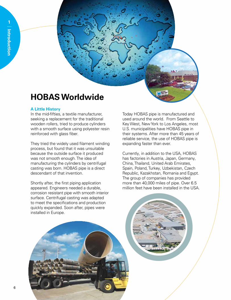
HOBAS Worldwide
Today HOBAS pipe is manufactured and used around the world. From Seattle to Key West, New York to Los Angeles, most U.S. municipalities have HOBAS pipe in their systems. After more than 45 years of reliable service, the use of HOBAS pipe is expanding faster than ever.
Currently, in addition to the USA, HOBAS has factories in Austria, Japan, Germany, China, Thailand, United Arab Emirates, Spain, Poland, Turkey, Uzbekistan, Czech Republic, Kazakhstan, Romania and Egypt. The group of companies has provided more than 40,000 miles of pipe. Over 6.5 million feet have been installed in the USA.
1
Intro
du
ction
7
Applications
2
Ap
plicatio
ns
HOBAS centrifugally cast fiberglass reinforced polymer mortar pipes are ideally suited for nearly all large diameter corrosive piping applications. Listed below are the most common environments, installations and services in which the pipe has been used.
Environments• Gravity sanitary sewers• Sewer force mains• Raw water • Sea water • Industrial effluents• Irrigation• Geo-thermal piping• Wastewater collection systems• Storm water and sewer water segregation systems• Odor control piping• WWTP piping• Potable water• Contaminated water• Cooling water• Foul air
Installation and Service Operation
Note: Products available for sustained temperatures over 150 º F.See Corrosion Resistance Guide in Appendix F.
Installation
Direct • •Bury Relining • •(Sliplining)Jacking & • •MicrotunnelingAbove • •GroundTunnel WaterwayCarrier • •
Pipe Bursting • •
Service OperationNon-Pressure Pressure
Direct bury installation at DFW Airport
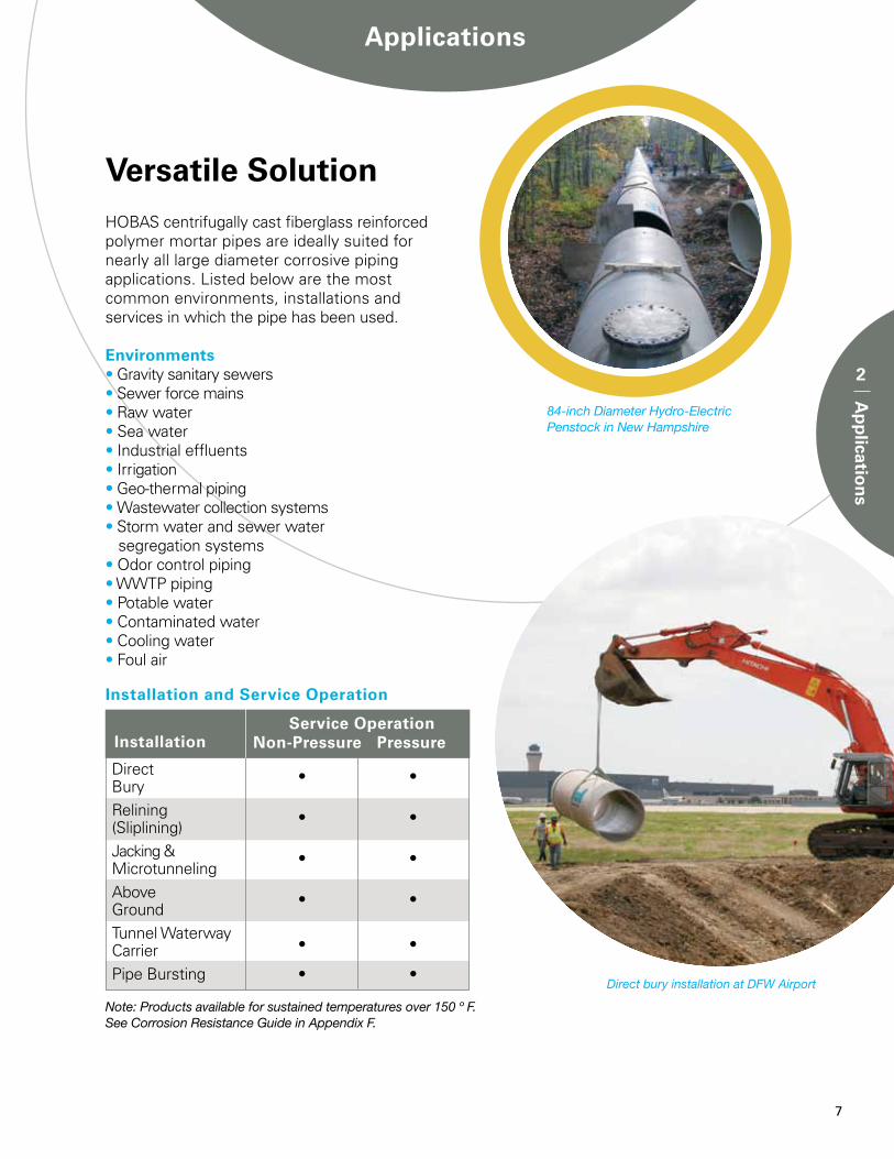
84-inch Diameter Hydro-Electric Penstock in New Hampshire
Versatile Solution
2
Ap
plicatio
ns
8
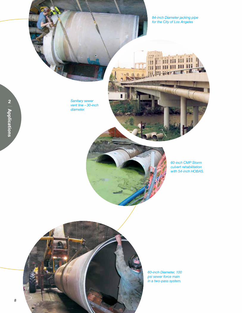
84-inch Diameter jacking pipe for the City of Los Angeles
Sanitary sewer vent line - 30-inch diameter.
60-inch CMP Storm culvert rehabilitation with 54-inch HOBAS.
60-inch Diameter, 100 psi sewer force main in a two-pass system.
9
Features/Benefits
3
Features/B
enefi
ts
HOBAS centrifugally cast fiberglass reinforced polymer mortar pipes have many outstanding features that provide numerous cost saving
• Long, maintenance-free service life.
• No costly add-on linings or coatings to damage, repair, inspect or maintain.
• No need for expensive cathodic protection or polybags to install and monitor.
• Ideal pipe for economical relining of corroded pipelines.
• Hydraulic characteristics are virtually unchanged with time.
• Easy to bury using methods routinely specified for traditional pipes.
• Performance is predictable and reliable.
• Deep covers handled with ease.
• Pipes are rugged and durable.
• Easy to grout annulus on sliplining and tunnel lining applications.
Inherent corrosionresistance
High stiffness design
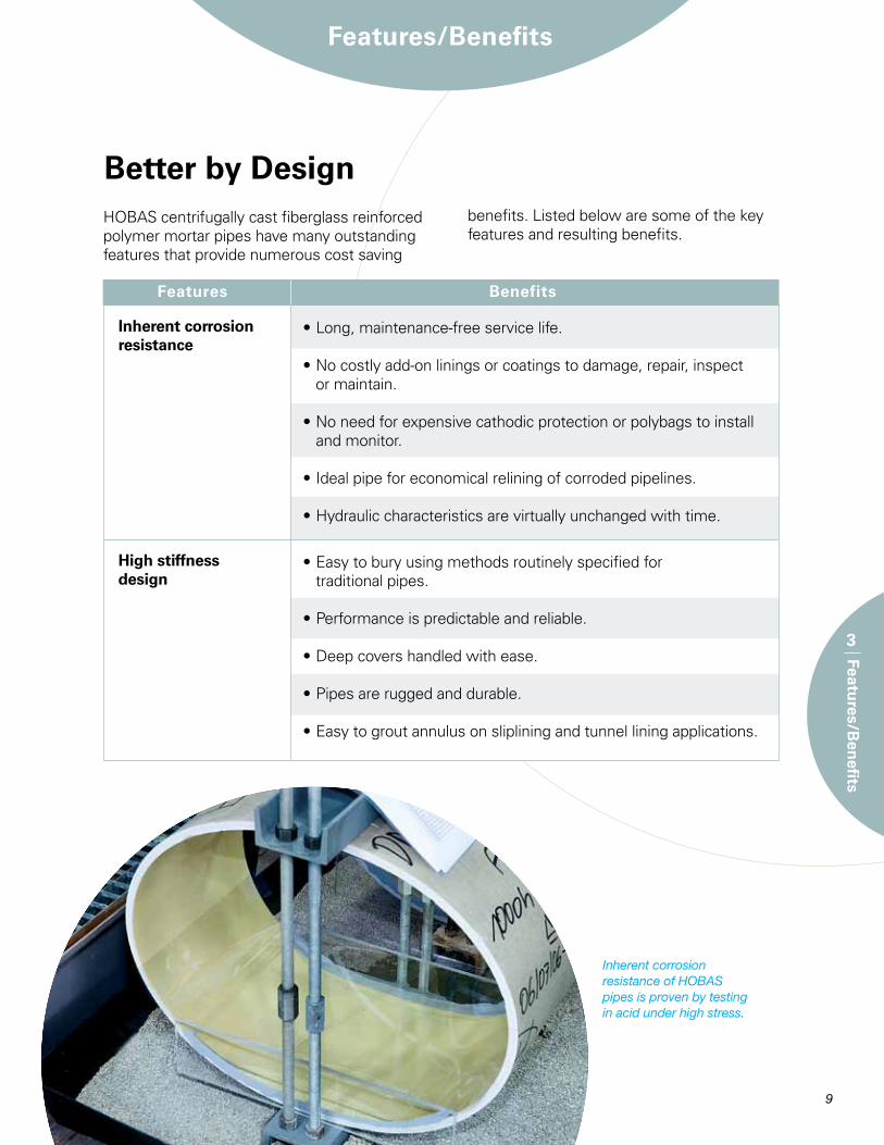
Inherent corrosion resistance of HOBAS pipes is proven by testing in acid under high stress.
benefits. Listed below are some of the key features and resulting benefits.
Better by Design
Features Benefits
10
• Deliver more fluid than any corrosion resistant pipe.
• Permits greatest recovery of flow in rehabilitated pipelines.
• Significant energy savings in pumped systems.
• Zero infiltration/exfiltration.
• No extra treatment costs.
• No pollution of ground waters.
• Full delivery of pumped fluids.
• No wasted time & expense trying to find and seal leaking joints to pass acceptance tests.
• No undermining of above structures and infrastructure.
Smooth interiorsurface & oversize ID’s
Bottle-tightjoints
Features Benefits
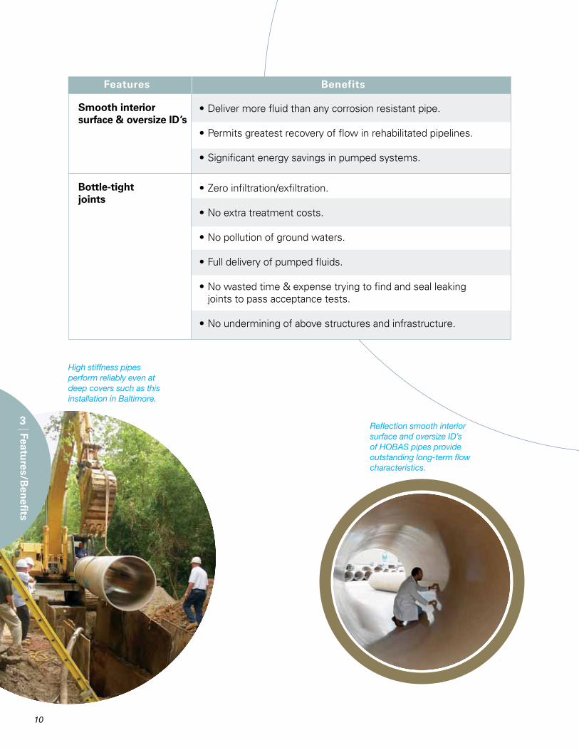
High stiffness pipes perform reliably even at deep covers such as this installation in Baltimore.
Reflection smooth interior surface and oversize ID’s of HOBAS pipes provide outstanding long-term flow characteristics.
3
Features/B
enefi
ts
11
3
Features/B
enefi
ts
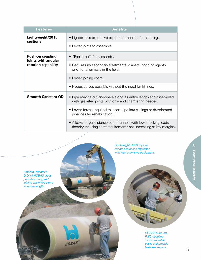
• Lighter, less expensive equipment needed for handling.
• Fewer joints to assemble.
• “Fool-proof,” fast assembly.
• Requires no secondary treatments, diapers, bonding agents or other chemicals in the field.
• Lower joining costs.
• Radius curves possible without the need for fittings.
• Pipe may be cut anywhere along its entire length and assembled with gasketed joints with only end chamfering needed.
• Lower forces required to insert pipe into casings or deteriorated pipelines for rehabilitation.
• Allows longer distance bored tunnels with lower jacking loads, thereby reducing shaft requirements and increasing safety margins.
Lightweight/20 ft. sections
Push-on coupling joints with angular rotation capability
Smooth Constant OD
Features Benefits
Lightweight HOBAS pipes handle easier and lay faster with less expensive equipment.
Smooth, constant O.D. of HOBAS pipes permits cutting and joining anywhere along its entire length.
HOBAS push-on FWC coupling joints assemble easily and provide leak-free service.
Features Benefits
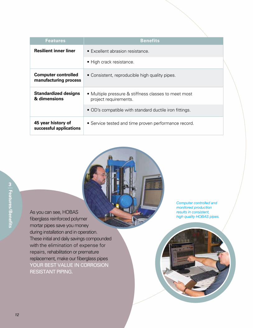
• Excellent abrasion resistance.
• High crack resistance.
• Consistent, reproducible high quality pipes.
• Multiple pressure & stiffness classes to meet most project requirements.
• OD’s compatible with standard ductile iron fittings.
• Service tested and time proven performance record.
Resilient inner liner
Computer controlled manufacturing process
Standardized designs & dimensions
45 year history ofsuccessful applications
Features Benefits
3
Features/B
enefi
ts
12
As you can see, HOBAS fiberglass reinforced polymer mortar pipes save you money during installation and in operation. These initial and daily savings compounded with the elimination of expense for repairs, rehabilitation or premature replacement, make our fiberglass pipes YOUR BEST VALUE IN CORROSION RESISTANT PIPING.
Computer controlled and monitored production results in consistent, high quality HOBAS pipes.
Features Benefits
13
Product Range
4
Pro
du
ct Ran
ge
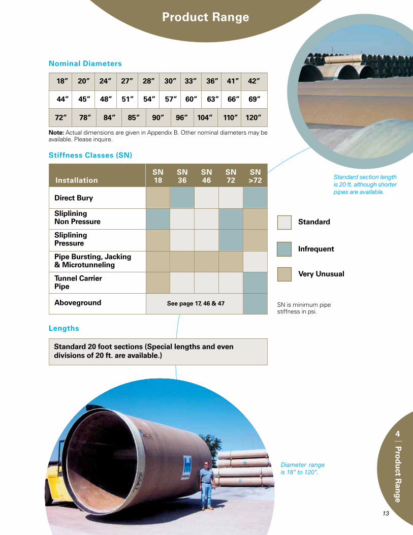
Note: Actual dimensions are given in Appendix B. Other nominal diameters may be available. Please inquire.
72” 78” 84” 85” 90” 96” 104” 110” 120”
18” 20” 24” 27” 28” 30” 33” 36” 41” 42”
Nominal Diameters
Stiffness Classes (SN)
Standard
Infrequent
Very Unusual
SN is minimum pipe stiffness in psi.
Direct Bury
SlipliningNon Pressure
SlipliningPressure
Pipe Bursting, Jacking& Microtunneling
Tunnel Carrier Pipe
Aboveground See page 17, 46 & 47
SN SN SN SN SN Installation 18 36 46 72 >72
Lengths
Standard 20 foot sections (Special lengths and even divisions of 20 ft. are available.)
Diameter range is 18” to 120”.
Standard section length is 20 ft. although shorter pipes are available.
44” 45” 48” 51” 54” 57” 60” 63” 66” 69”
14
4
Pro
du
ct Ran
ge
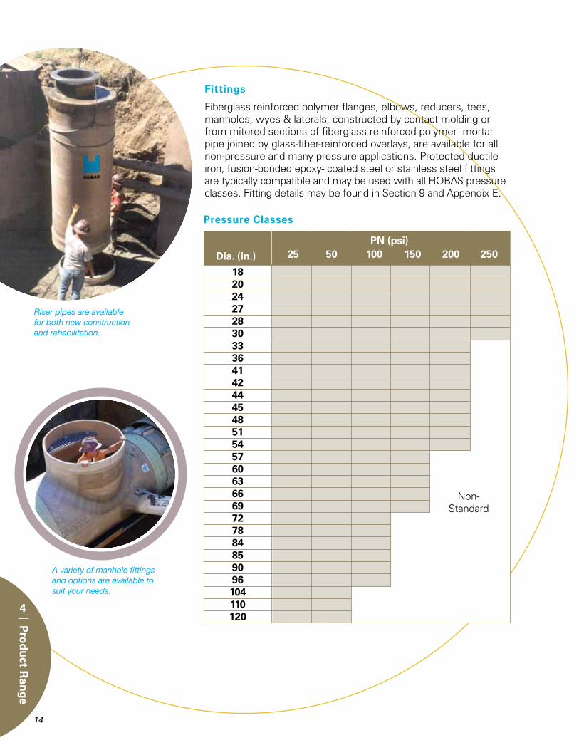
Pressure Classes
Dia. (in.)PN (psi)
25 50 100 150 200 250
Non-Standard
18 20 24 27 28 30 33 36 41 42 44 45 48 51 54 57 60 63 66 69 72 78 84 85 90 96 104 110 120
Fittings
Fiberglass reinforced polymer flanges, elbows, reducers, tees, manholes, wyes & laterals, constructed by contact molding or from mitered sections of fiberglass reinforced polymer mortar pipe joined by glass-fiber-reinforced overlays, are available for all non-pressure and many pressure applications. Protected ductile iron, fusion-bonded epoxy- coated steel or stainless steel fittings are typically compatible and may be used with all HOBAS pressure classes. Fitting details may be found in Section 9 and Appendix E.
Riser pipes are available for both new construction and rehabilitation.
A variety of manhole fittings and options are available to suit your needs.
15
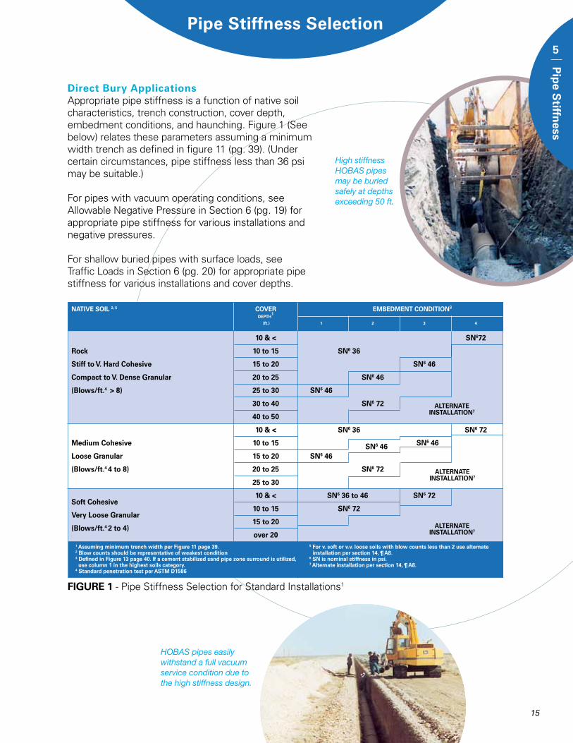
FIGURE 1 - Pipe Stiffness Selection for Standard Installations1
ALTERNATE INSTALLATION7
ALTERNATE INSTALLATION7
ALTERNATE INSTALLATION7
SN6 46 SN6 46
Pipe Stiffness Selection
Direct Bury ApplicationsAppropriate pipe stiffness is a function of native soil characteristics, trench construction, cover depth, embedment conditions, and haunching. Figure 1 (See below) relates these parameters assuming a minimum width trench as defined in figure 11 (pg. 39). (Under certain circumstances, pipe stiffness less than 36 psi may be suitable.)
For pipes with vacuum operating conditions, see Allowable Negative Pressure in Section 6 (pg. 19) for appropriate pipe stiffness for various installations and negative pressures.
For shallow buried pipes with surface loads, see Traffic Loads in Section 6 (pg. 20) for appropriate pipe stiffness for various installations and cover depths.
HOBAS pipes easily withstand a full vacuum service condition due to the high stiffness design.
High stiffness HOBAS pipes may be buried safely at depths exceeding 50 ft.
NATIVE SOIL 2, 5 COVER EMBEDMENT CONDITION3
DEPTH1
(ft.) 1 2 3 4
10 & < SN672
Rock 10 to 15 SN6 36
Stiff to V. Hard Cohesive 15 to 20 SN6 46
Compact to V. Dense Granular 20 to 25 SN6 46
(Blows/ft.4 > 8) 25 to 30 SN6 46
30 to 40 SN6 72
40 to 50
10 & < SN6 36 SN6 72
Medium Cohesive 10 to 15
Loose Granular 15 to 20 SN6 46
(Blows/ft.4 4 to 8) 20 to 25 SN6 72
25 to 30
10 & < SN6 36 to 46 SN6 72Soft Cohesive
10 to 15 SN6 72Very Loose Granular
15 to 20(Blows/ft.4 2 to 4)
over 201 Assuming minimum trench width per Figure 11 page 39. 5 For v. soft or v.v. loose soils with blow counts less than 2 use alternate2 Blow counts should be representative of weakest condition installation per section 14, ¶ A8.3 Defined in Figure 13 page 40. If a cement stabilized sand pipe zone surround is utilized, 6 SN is nominal stiffness in psi. use column 1 in the highest soils category. 7 Alternate installation per section 14, ¶ A8.4 Standard penetration test per ASTM D1586
5
Pip
e Stiffn
ess
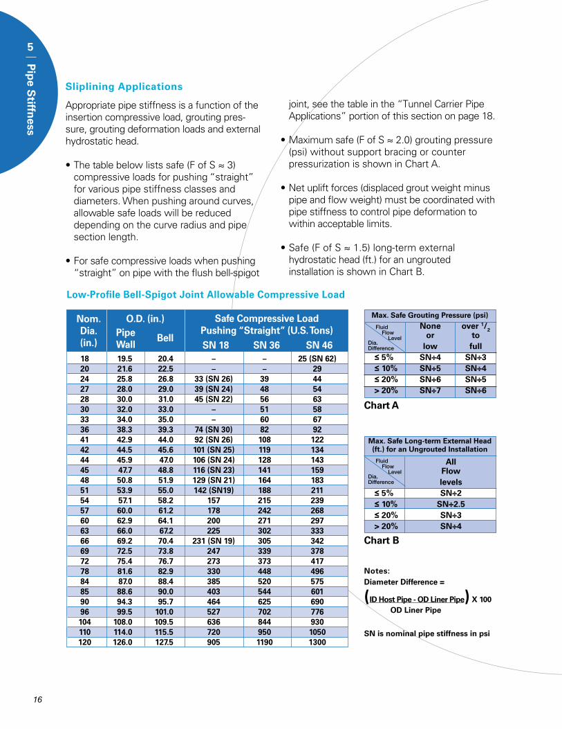
Sliplining Applications
Appropriate pipe stiffness is a function of the insertion compressive load, grouting pres-sure, grouting deformation loads and external hydrostatic head.
• The table below lists safe (F of S ≈ 3) compressive loads for pushing “straight” for various pipe stiffness classes and diameters. When pushing around curves, allowable safe loads will be reduced depending on the curve radius and pipe section length.
• For safe compressive loads when pushing “straight” on pipe with the flush bell-spigot
joint, see the table in the “Tunnel Carrier Pipe Applications” portion of this section on page 18.
• Maximum safe (F of S ≈ 2.0) grouting pressure (psi) without support bracing or counter pressurization is shown in Chart A.
• Net uplift forces (displaced grout weight minus pipe and flow weight) must be coordinated with pipe stiffness to control pipe deformation to within acceptable limits.
• Safe (F of S ≈ 1.5) long-term external hydrostatic head (ft.) for an ungrouted installation is shown in Chart B.
Low-Profile Bell-Spigot Joint Allowable Compressive Load
Nom. Dia. (in.)
O.D. (in.)PipeWall
Bell
Safe Compressive LoadPushing “Straight” (U.S. Tons)
SN 18 SN 36 SN 46
Max. Safe Long-term External Head (ft.) for an Ungrouted Installation
All Flow levels ≤ 5% SN÷2 ≤ 10% SN÷2.5 ≤ 20% SN÷3 > 20% SN÷4
Fluid Flow Level
Dia.Difference
Chart B
Fluid Flow Level
Max. Safe Grouting Pressure (psi)
None over 1/2 or to low full ≤ 5% SN÷4 SN÷3 ≤ 10% SN÷5 SN÷4 ≤ 20% SN÷6 SN÷5 > 20% SN÷7 SN÷6
Chart A
Dia.Difference
Notes:Diameter Difference =
(ID Host Pipe - OD Liner Pipe) X 100 OD Liner Pipe
SN is nominal pipe stiffness in psi
5
Pip
e Stiffn
ess
16
18 19.5 20.4 – – 25 (SN 62) 20 21.6 22.5 – – 29 24 25.8 26.8 33 (SN 26) 39 44 27 28.0 29.0 39 (SN 24) 48 54 28 30.0 31.0 45 (SN 22) 56 63 30 32.0 33.0 – 51 58 33 34.0 35.0 – 60 67 36 38.3 39.3 74 (SN 30) 82 92 41 42.9 44.0 92 (SN 26) 108 122 42 44.5 45.6 101 (SN 25) 119 134 44 45.9 47.0 106 (SN 24) 128 143 45 47.7 48.8 116 (SN 23) 141 159 48 50.8 51.9 129 (SN 21) 164 183 51 53.9 55.0 142 (SN19) 188 211 54 57.1 58.2 157 215 239 57 60.0 61.2 178 242 268 60 62.9 64.1 200 271 297 63 66.0 67.2 225 302 333 66 69.2 70.4 231 (SN 19) 305 342 69 72.5 73.8 247 339 378 72 75.4 76.7 273 373 417 78 81.6 82.9 330 448 496 84 87.0 88.4 385 520 575 85 88.6 90.0 403 544 601 90 94.3 95.7 464 625 690 96 99.5 101.0 527 702 776 104 108.0 109.5 636 844 930 110 114.0 115.5 720 950 1050 120 126.0 127.5 905 1190 1300
17
5
Pip
e Stiffn
ess
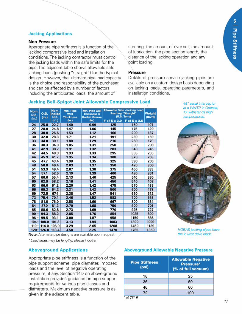
Note: Alternate pipe designs are available upon request.
Allowable Safe Jacking Load Pushing “Straight”
(U.S. Tons)
F of S = 3.0
Min. Pipe Wall Thickness @
Gasket Groove(in.)
Nom. Dia.(in.)
O.D.(in.)
Nom. InsideDia.(in.)
Min. Pipe Wall
Thickness (in.) F of S = 2.5
Jacking Bell-Spigot Joint Allowable Compressive Load
Weight (lb/ft)
*****
* Lead times may be lengthy, please inquire.
Jacking Applications
Non-PressureAppropriate pipe stiffness is a function of the jacking compressive load and installation conditions. The jacking contractor must control the jacking loads within the safe limits for the pipe. The adjacent table shows allowable safe jacking loads (pushing “straight”) for the typical design. However, the ultimate pipe load capacity is the choice and responsibility of the purchaser and can be affected by a number of factors including the anticipated loads, the amount of
steering, the amount of over-cut, the amount of lubrication, the pipe section length, the distance of the jacking operation and any point loading.
PressureDetails of pressure service jacking pipes are available on a custom design basis depending on jacking loads, operating parameters, and installation conditions.
Aboveground Applications
Appropriate pipe stiffness is a function of the pipe support scheme, pipe diameter, imposed loads and the level of negative operating pressure, if any. Section 14D on above-ground installation provides guidance on pipe support requirements for various pipe classes and diameters. Maximum negative pressure is as given in the adjacent table.
48” aerial interceptor at a WWTP in Odessa, TX withstands high temperatures.
HOBAS jacking pipes have the lowest drive loads.
Aboveground Allowable Negative Pressure
Allowable NegativePressure*
(% of full vacuum)
Pipe Stiffness(psi)
18 25 36 50 46 60 72 100* at 75° F.
24 25.8 22.7 1.40 0.99 125 150 107 27 28.0 24.8 1.47 1.06 145 175 120 28 30.0 26.6 1.53 1.12 166 200 137 30 32.0 28.3 1.71 1.21 191 230 159 33 34.0 30.1 1.80 1.29 216 260 179 36 38.3 34.3 1.85 1.31 250 300 208 41 42.9 38.7 1.91 1.32 283 340 245 42 44.5 40.3 1.93 1.33 295 355 255 44 45.9 41.7 1.95 1.34 308 370 263 45 47.7 43.4 1.98 1.35 325 390 280 48 50.8 46.4 2.03 1.37 350 420 306 51 53.9 49.4 2.07 1.38 375 450 333 54 57.1 52.5 2.10 1.39 400 480 361 57 60.0 55.4 2.13 1.40 425 510 380 60 62.9 58.2 2.16 1.41 450 540 408 63 66.0 61.2 2.20 1.42 475 570 438 66 69.2 64.2 2.31 1.43 500 600 478 69 72.5 67.4 2.38 1.47 541 650 512 72 75.4 70.1 2.46 1.52 583 700 553 78 81.6 76.0 2.58 1.60 667 800 634 84 87.0 81.2 2.70 1.68 750 900 701 85 88.6 82.8 2.73 1.69 770 925 727 90 94.3 88.2 2.85 1.76 854 1025 800 96 99.5 93.1 3.00 1.87 958 1150 886 104 108.0 101.3 3.13 1.94 1083 1300 1009 110 114.0 106.9 3.29 2.05 1208 1450 1129 120 126.0 118.4 3.58 2.25 1470 1765 1350
5
Pip
e Stiffn
ess
18
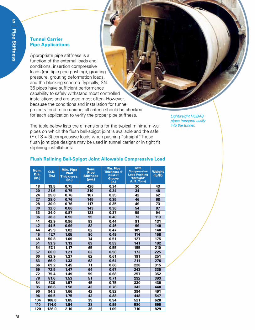
Flush Relining Bell-Spigot Joint Allowable Compressive Load
Tunnel Carrier Pipe Applications
Appropriate pipe stiffness is a function of the external loads and conditions, insertion compressive loads (multiple pipe pushing), grouting pressure, grouting deformation loads, and the blocking scheme. Typically, SN 36 pipes have sufficient performance capability to safely withstand most controlled installations and are used most often. However, because the conditions and installation for tunnel projects tend to be unique, all criteria should be checked for each application to verify the proper pipe stiffness.
The table below lists the dimensions for the typical minimum wall pipes on which the flush bell-spigot joint is available and the safe (F of S ≈ 3) compressive loads when pushing “straight”. These flush joint pipe designs may be used in tunnel carrier or in tight fit sliplining installations.
Lightweight HOBAS pipes transport easily into the tunnel.
Safe Compressive Load Pushing
“Straight” (U.S. Tons)
Min. Pipe Thickness @
Gasket Groove
(in.)
Min. Pipe Wall
Thickness.(in.)
O.D.(in.)
Nom. Dia.(in.)
Nom.Pipe
Stiffness(psi.)
Weight (lb/ft)
18 19.5 0.75 426 0.34 30 43 20 21.6 0.75 310 0.34 34 48 24 25.8 0.76 187 0.35 42 62 27 28.0 0.76 145 0.35 46 68 28 30.0 0.76 117 0.35 49 73 30 32.0 0.86 143 0.36 54 87 33 34.0 0.87 123 0.37 59 94 36 38.3 0.90 95 0.40 73 110 41 42.9 0.96 83 0.44 91 131 42 44.5 0.99 82 0.46 99 140 44 45.9 1.02 82 0.47 105 148 45 47.7 1.05 80 0.49 114 158 48 50.8 1.09 74 0.51 127 175 51 53.9 1.13 69 0.53 141 192 54 57.1 1.17 65 0.55 155 210 57 60.0 1.21 62 0.58 173 225 60 62.9 1.27 62 0.61 191 251 63 66.0 1.33 62 0.64 211 276 66 69.2 1.45 71 0.66 228 315 69 72.5 1.47 64 0.67 243 335 72 75.4 1.49 59 0.68 257 352 78 81.6 1.53 51 0.71 292 393 84 87.0 1.57 45 0.75 330 430 85 88.6 1.58 43 0.76 342 440 90 94.3 1.66 42 0.82 394 491 96 99.5 1.75 42 0.88 448 547 104 108.0 1.85 39 0.94 521 628 110 114.0 1.94 38 0.99 580 695 120 126.0 2.10 36 1.09 710 829
19
Pipe Capabilities & Design
6
Pip
e Cap
abilities
& D
esign
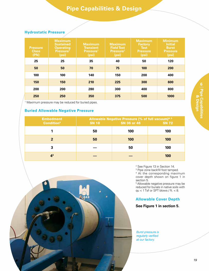
Buried Allowable Negative Pressure
Hydrostatic Pressure
1 Maximum pressure may be reduced for buried pipes.
Maximum Maximum Minimum Sustained Maximum Maximum Factory Initial Pressure Operating Transient Field Test Test Burst Class Pressure1 Pressure1 Pressure1 Pressure Pressure (PN) (psi) (psi) (psi) (psi) (psi)
25 25 35 40 50 120
50 50 70 75 100 200
100 100 140 150 200 400
150 150 210 225 300 600
200 200 280 300 400 800
250 250 350 375 500 1000
Embedment Allowable Negative Pressure (% of full vacuum)4, 5
Condition2 SN 18 SN 36 or 46 SN 72
1 50 100 100
2 50 100 100
3 –– 50 100
43 –– –– 100
2 See Figure 13 in Section 14.3 Pipe zone backfill foot tamped.4 At the corresponding maximum cover depth shown on figure 1 in section 5.5 Allowable negative pressure may be reduced for burials in native soils with qu < 1 Tsf or SPT blows / ft. < 8.
Burst pressure is regularly verified at our factory.
See Figure 1 in section 5.
Allowable Cover Depth
20
6
Pip
e Cap
abilities
& D
esign
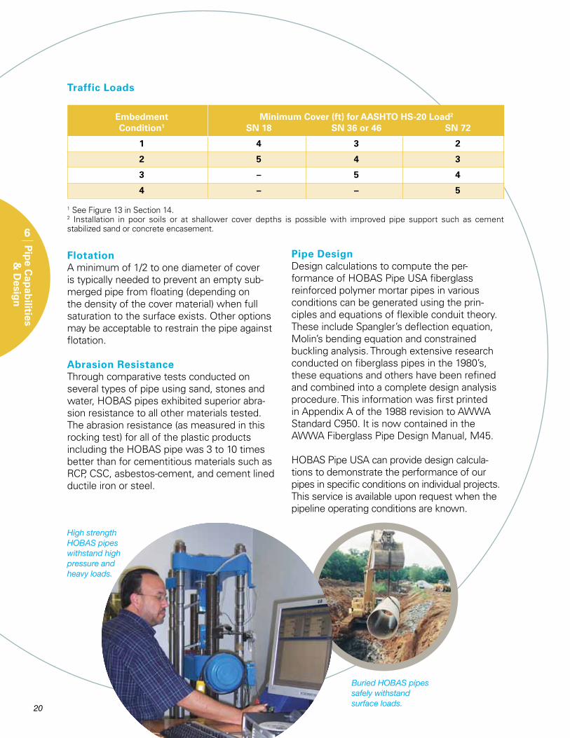
Traffic Loads
1 See Figure 13 in Section 14.2 Installation in poor soils or at shallower cover depths is possible with improved pipe support such as cement stabilized sand or concrete encasement.
Embedment Minimum Cover (ft) for AASHTO HS-20 Load2
Condition1 SN 18 SN 36 or 46 SN 72
1 4 3 2
2 5 4 3
3 – 5 4
4 – – 5
FlotationA minimum of 1/2 to one diameter of cover is typically needed to prevent an empty sub-merged pipe from floating (depending on the density of the cover material) when full saturation to the surface exists. Other options may be acceptable to restrain the pipe against flotation.
Abrasion ResistanceThrough comparative tests conducted on several types of pipe using sand, stones and water, HOBAS pipes exhibited superior abra-sion resistance to all other materials tested. The abrasion resistance (as measured in this rocking test) for all of the plastic products including the HOBAS pipe was 3 to 10 times better than for cementitious materials such as RCP, CSC, asbestos-cement, and cement lined ductile iron or steel.
Pipe DesignDesign calculations to compute the per-formance of HOBAS Pipe USA fiberglass reinforced polymer mortar pipes in various conditions can be generated using the prin-ciples and equations of flexible conduit theory. These include Spangler’s deflection equation, Molin’s bending equation and constrained buckling analysis. Through extensive research conducted on fiberglass pipes in the 1980’s, these equations and others have been refined and combined into a complete design analysis procedure. This information was first printed in Appendix A of the 1988 revision to AWWA Standard C950. It is now contained in the AWWA Fiberglass Pipe Design Manual, M45.
HOBAS Pipe USA can provide design calcula-tions to demonstrate the performance of our pipes in specific conditions on individual projects. This service is available upon request when the pipeline operating conditions are known.
Buried HOBAS pipes safely withstand surface loads.
High strength HOBAS pipes withstand high pressure and heavy loads.
21
Hydraulics
7
Hyd
raulics
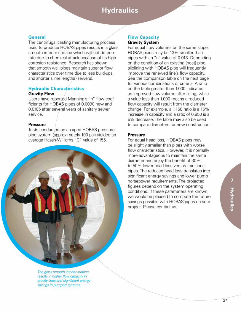
GeneralThe centrifugal casting manufacturing process used to produce HOBAS pipes results in a glass smooth interior surface which will not deterio-rate due to chemical attack because of its high corrosion resistance. Research has shown that smooth wall pipes maintain superior flow characteristics over time due to less build-ups and shorter slime lengths (sewers).
Hydraulic CharacteristicsGravity FlowUsers have reported Manning’s “n” flow coef-ficients for HOBAS pipes of 0.0090 new and 0.0105 after several years of sanitary sewer service.
PressureTests conducted on an aged HOBAS pressure pipe system (approximately 100 psi) yielded an average Hazen-Williams “C” value of 155.
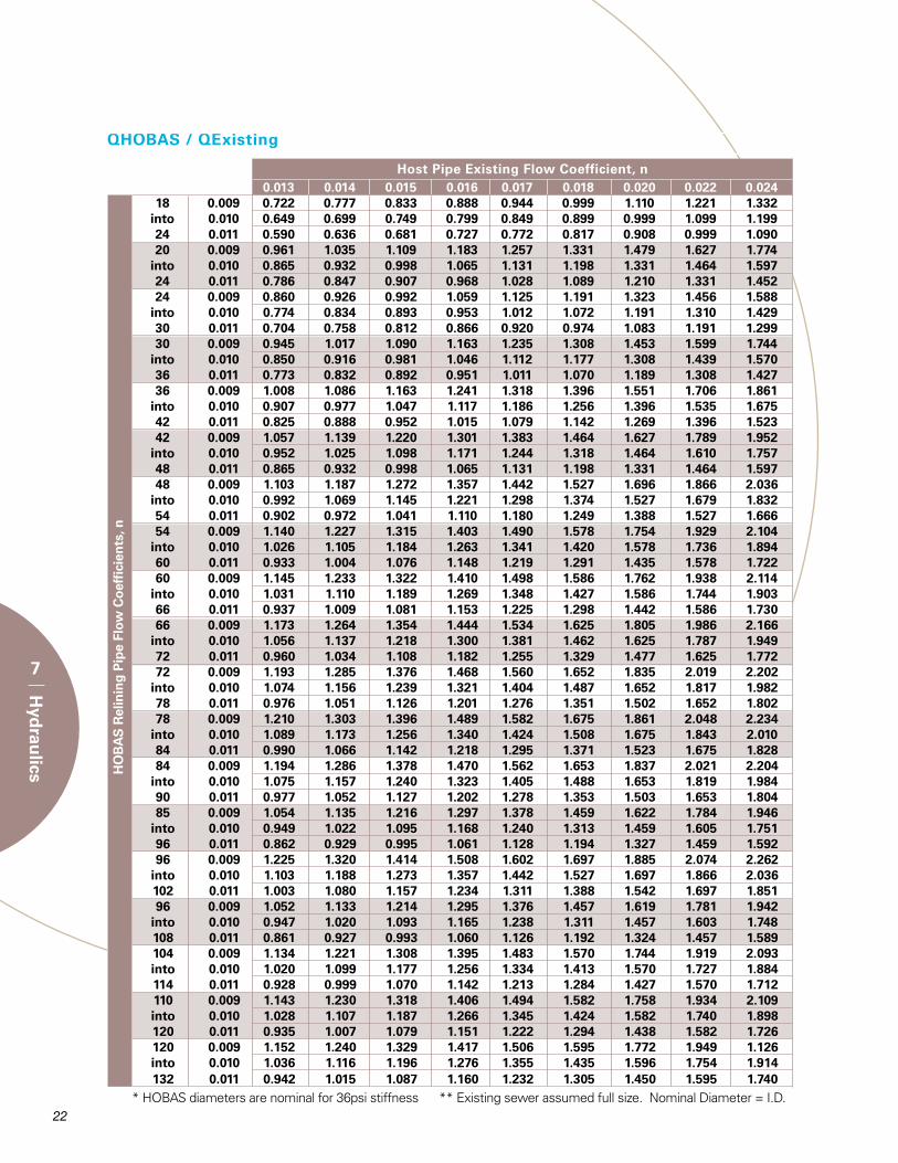
Flow CapacityGravity SystemFor equal flow volumes on the same slope, HOBAS pipes may be 13% smaller than pipes with an “n” value of 0.013. Depending on the condition of an existing (host) pipe, sliplining with HOBAS pipe will frequently improve the renewed line’s flow capacity. See the comparison table on the next page for various combinations of criteria. A ratio on the table greater than 1.000 indicates an improved flow volume after lining, while a value less than 1.000 means a reduced flow capacity will result from the diameter change. For example, a 1.150 ratio is a 15% increase in capacity and a ratio of 0.950 is a 5% decrease. The table may also be used to compare diameters for new construction.
PressureFor equal head loss, HOBAS pipes may be slightly smaller than pipes with worse flow characteristics. However, it is normally more advantageous to maintain the same diameter and enjoy the benefit of 30% to 50% lower head loss versus traditional pipes. The reduced head loss translates into significant energy savings and lower pump horsepower requirements. The projected figures depend on the system operating conditions. If these parameters are known, we would be pleased to compute the future savings possible with HOBAS pipes on your project. Please contact us.
The glass smooth interior surface results in higher flow capacity in gravity lines and significant energy savings in pumped systems.
HO
BA
S R
elin
ing
Pip
e Fl
ow C
oef
fici
ents
, n
Host Pipe Existing Flow Coefficient, n
QHOBAS / QExisting
22
7
Hyd
raulics
0.013 0.014 0.015 0.016 0.017 0.018 0.020 0.022 0.024 18 0.009 0.722 0.777 0.833 0.888 0.944 0.999 1.110 1.221 1.332 into 0.010 0.649 0.699 0.749 0.799 0.849 0.899 0.999 1.099 1.199 24 0.011 0.590 0.636 0.681 0.727 0.772 0.817 0.908 0.999 1.090 20 0.009 0.961 1.035 1.109 1.183 1.257 1.331 1.479 1.627 1.774 into 0.010 0.865 0.932 0.998 1.065 1.131 1.198 1.331 1.464 1.597 24 0.011 0.786 0.847 0.907 0.968 1.028 1.089 1.210 1.331 1.452 24 0.009 0.860 0.926 0.992 1.059 1.125 1.191 1.323 1.456 1.588 into 0.010 0.774 0.834 0.893 0.953 1.012 1.072 1.191 1.310 1.429 30 0.011 0.704 0.758 0.812 0.866 0.920 0.974 1.083 1.191 1.299 30 0.009 0.945 1.017 1.090 1.163 1.235 1.308 1.453 1.599 1.744 into 0.010 0.850 0.916 0.981 1.046 1.112 1.177 1.308 1.439 1.570 36 0.011 0.773 0.832 0.892 0.951 1.011 1.070 1.189 1.308 1.427 36 0.009 1.008 1.086 1.163 1.241 1.318 1.396 1.551 1.706 1.861 into 0.010 0.907 0.977 1.047 1.117 1.186 1.256 1.396 1.535 1.675 42 0.011 0.825 0.888 0.952 1.015 1.079 1.142 1.269 1.396 1.523 42 0.009 1.057 1.139 1.220 1.301 1.383 1.464 1.627 1.789 1.952 into 0.010 0.952 1.025 1.098 1.171 1.244 1.318 1.464 1.610 1.757 48 0.011 0.865 0.932 0.998 1.065 1.131 1.198 1.331 1.464 1.597 48 0.009 1.103 1.187 1.272 1.357 1.442 1.527 1.696 1.866 2.036 into 0.010 0.992 1.069 1.145 1.221 1.298 1.374 1.527 1.679 1.832 54 0.011 0.902 0.972 1.041 1.110 1.180 1.249 1.388 1.527 1.666 54 0.009 1.140 1.227 1.315 1.403 1.490 1.578 1.754 1.929 2.104 into 0.010 1.026 1.105 1.184 1.263 1.341 1.420 1.578 1.736 1.894 60 0.011 0.933 1.004 1.076 1.148 1.219 1.291 1.435 1.578 1.722 60 0.009 1.145 1.233 1.322 1.410 1.498 1.586 1.762 1.938 2.114 into 0.010 1.031 1.110 1.189 1.269 1.348 1.427 1.586 1.744 1.903 66 0.011 0.937 1.009 1.081 1.153 1.225 1.298 1.442 1.586 1.730 66 0.009 1.173 1.264 1.354 1.444 1.534 1.625 1.805 1.986 2.166 into 0.010 1.056 1.137 1.218 1.300 1.381 1.462 1.625 1.787 1.949 72 0.011 0.960 1.034 1.108 1.182 1.255 1.329 1.477 1.625 1.772 72 0.009 1.193 1.285 1.376 1.468 1.560 1.652 1.835 2.019 2.202 into 0.010 1.074 1.156 1.239 1.321 1.404 1.487 1.652 1.817 1.982 78 0.011 0.976 1.051 1.126 1.201 1.276 1.351 1.502 1.652 1.802 78 0.009 1.210 1.303 1.396 1.489 1.582 1.675 1.861 2.048 2.234 into 0.010 1.089 1.173 1.256 1.340 1.424 1.508 1.675 1.843 2.010 84 0.011 0.990 1.066 1.142 1.218 1.295 1.371 1.523 1.675 1.828 84 0.009 1.194 1.286 1.378 1.470 1.562 1.653 1.837 2.021 2.204 into 0.010 1.075 1.157 1.240 1.323 1.405 1.488 1.653 1.819 1.984 90 0.011 0.977 1.052 1.127 1.202 1.278 1.353 1.503 1.653 1.804 85 0.009 1.054 1.135 1.216 1.297 1.378 1.459 1.622 1.784 1.946 into 0.010 0.949 1.022 1.095 1.168 1.240 1.313 1.459 1.605 1.751 96 0.011 0.862 0.929 0.995 1.061 1.128 1.194 1.327 1.459 1.592 96 0.009 1.225 1.320 1.414 1.508 1.602 1.697 1.885 2.074 2.262 into 0.010 1.103 1.188 1.273 1.357 1.442 1.527 1.697 1.866 2.036 102 0.011 1.003 1.080 1.157 1.234 1.311 1.388 1.542 1.697 1.851 96 0.009 1.052 1.133 1.214 1.295 1.376 1.457 1.619 1.781 1.942 into 0.010 0.947 1.020 1.093 1.165 1.238 1.311 1.457 1.603 1.748 108 0.011 0.861 0.927 0.993 1.060 1.126 1.192 1.324 1.457 1.589 104 0.009 1.134 1.221 1.308 1.395 1.483 1.570 1.744 1.919 2.093 into 0.010 1.020 1.099 1.177 1.256 1.334 1.413 1.570 1.727 1.884 114 0.011 0.928 0.999 1.070 1.142 1.213 1.284 1.427 1.570 1.712 110 0.009 1.143 1.230 1.318 1.406 1.494 1.582 1.758 1.934 2.109 into 0.010 1.028 1.107 1.187 1.266 1.345 1.424 1.582 1.740 1.898 120 0.011 0.935 1.007 1.079 1.151 1.222 1.294 1.438 1.582 1.726 120 0.009 1.152 1.240 1.329 1.417 1.506 1.595 1.772 1.949 1.126 into 0.010 1.036 1.116 1.196 1.276 1.355 1.435 1.596 1.754 1.914 132 0.011 0.942 1.015 1.087 1.160 1.232 1.305 1.450 1.595 1.740 * HOBAS diameters are nominal for 36psi stiffness ** Existing sewer assumed full size. Nominal Diameter = I.D.
23
Joints
8
Join
ts
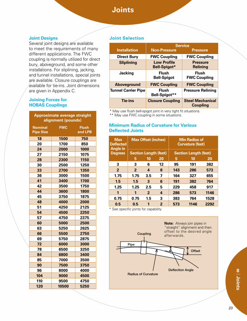
Joint Designs Several joint designs are available to meet the requirements of many different applications. The FWC coupling is normally utilized for direct bury, aboveground, and some other installations. For sliplining, jacking, and tunnel installations, special joints are available. Closure couplings are available for tie-ins. Joint dimensions are given in Appendix C.
Joint Selection
* May use flush bell-spigot joint in very tight fit situations.** May use FWC coupling in some situations.
Direct Bury FWC Coupling FWC Coupling
Jacking Flush Flush Bell-Spigot FWC Coupling
Low Profile Pressure Bell-Spigot* Relining
Sliplining
Aboveground FWC Coupling FWC Coupling Tunnel Carrier Pipe Flush Pressure Relining Bell-Spigot** Tie-ins Closure Coupling Steel Mechanical Coupling
Service Installation Non-Pressure Pressure
Minimum Radius of Curvature for Various Deflected Joints
Joining Forces for HOBAS Couplings
Approximate average straight alignment (pounds)
Nominal FWC Flush Pipe Size and LPB
18 1500 750 20 1700 850 24 2000 1000 27 2150 1075 28 2300 1150 30 2500 1250 33 2700 1350 36 3000 1500 41 3400 1700 42 3500 1750 44 3600 1800 45 3750 1875 48 4000 2000 51 4250 2125 54 4500 2250 57 4750 2375 60 5000 2500 63 5250 2625 66 5500 2750 69 5750 2875 72 6000 3000 78 6500 3250 84 6800 3400 85 7000 3500 90 7500 3750 96 8000 4000 104 9000 4500 110 9500 4750 120 10500 5250
Note: Always join pipes in “straight” alignment and then offset to the desired angle afterwards.
Max Max Offset (inches) Min Radius of Deflected Curvature (feet) Angle in Degrees Section Length (feet) Section Length (feet) 5 10 20 5 10 20 3 3 6 12 95 191 382 2 2 4 8 143 286 573 1.75 1.75 3.5 7 164 327 655 1.5 1.5 3 6 191 382 764 1.25 1.25 2.5 5 229 458 917 1 1 2 4 286 573 1146 0.75 0.75 1.5 3 383 764 1528 0.5 0.5 1 2 573 1146 2292* See specific joints for capability
FWC Coupling
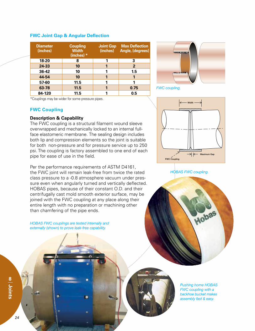
Description & CapabilityThe FWC coupling is a structural filament wound sleeve overwrapped and mechanically locked to an internal full-face elastomeric membrane. The sealing design includes both lip and compression elements so the joint is suitable for both non-pressure and for pressure service up to 250 psi. The coupling is factory assembled to one end of each pipe for ease of use in the field.
Per the performance requirements of ASTM D4161, the FWC joint will remain leak-free from twice the rated class pressure to a -0.8 atmosphere vacuum under pres-sure even when angularly turned and vertically deflected. HOBAS pipes, because of their constant O.D. and their centrifugally cast mold smooth exterior surface, may be joined with the FWC coupling at any place along their entire length with no preparation or machining other than chamfering of the pipe ends.
FWC Joint Gap & Angular Deflection
*Couplings may be wider for some pressure pipes.
Diameter Coupling Joint Gap Max Deflection (inches) Width (inches) Angle, (degrees) (inches) * 18-20 8 1 3 24-33 10 1 2 36-42 10 1 1.5 44-54 10 1 1 57-60 11.5 1 1 63-78 11.5 1 0.75 84-120 11.5 1 0.5
FWC coupling.
HOBAS FWC coupling.
Pushing home HOBAS FWC coupling with a backhoe bucket makes assembly fast & easy.
HOBAS FWC couplings are tested internally and externally (shown) to prove leak-free capability.
24
8
Join
ts
25
8
Join
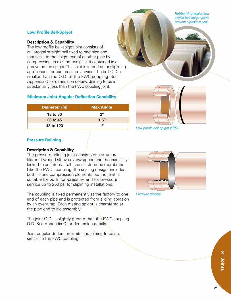
tsRubber-ring-sealed low profile bell-spigot joints provide a positive seal.
Low Profile Bell-Spigot
Description & CapabilityThe low profile bell-spigot joint consists of an integral straight bell fixed to one pipe end that seals to the spigot end of another pipe by compressing an elastomeric gasket contained in a groove on the spigot. This joint is intended for sliplining applications for non-pressure service. The bell O.D. is smaller than the O.D. of the FWC coupling. See Appendix C for dimension details. Joining force is substantially less than the FWC coupling joint.
Low profile bell-spigot (LPB).
Diameter (in) Max Angle
18to30 2º 33to45 1.5º 48to120 1º
Minimum Joint Angular Deflection Capability
Pressure Relining
Description & CapabilityThe pressure relining joint consists of a structural filament wound sleeve overwrapped and mechanically locked to an internal full-face elastomeric membrane. Like the FWC coupling, the sealing design includes both lip and compression elements, so the joint is suitable for both non-pressure and for pressure service up to 250 psi for sliplining installations.
The coupling is fixed permanently at the factory to one end of each pipe and is protected from sliding abrasion by an overwrap. Each mating spigot is chamfered at the pipe end to aid assembly.
The joint O.D. is slightly greater than the FWC coupling O.D. See Appendix C for dimension details.
Joint angular deflection limits and joining force are similar to the FWC coupling.
Pressure relining.
26
8
Join
ts
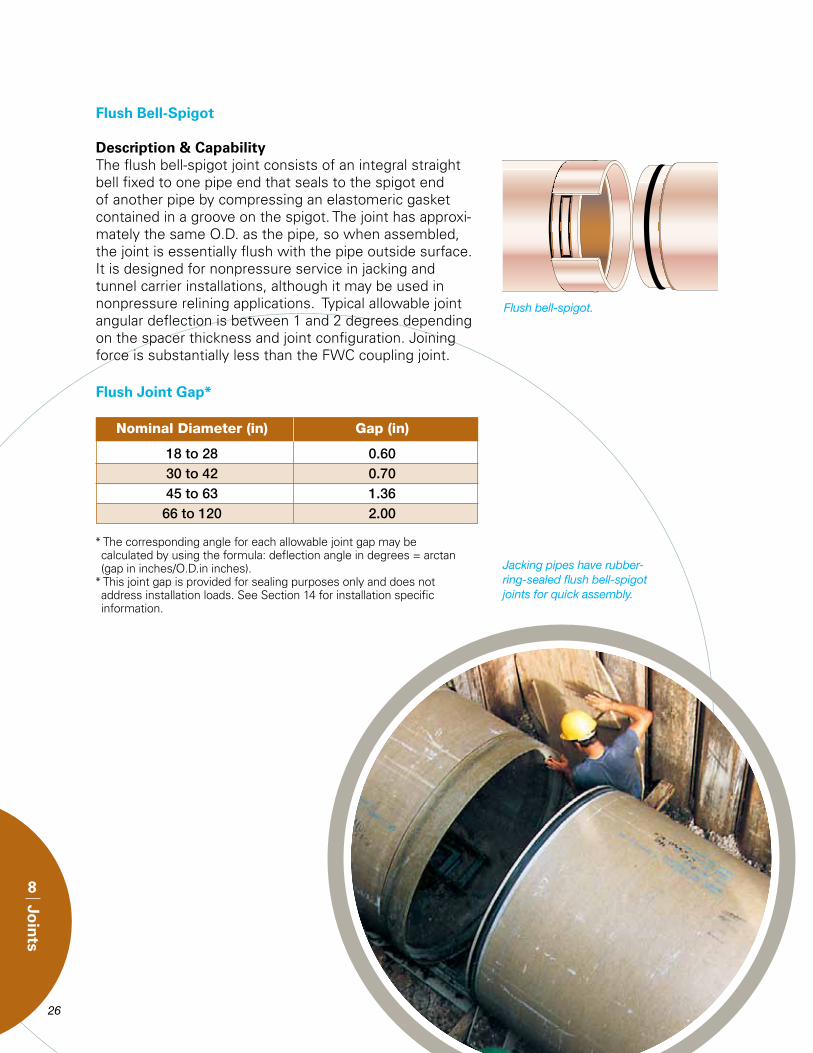
Flush Bell-Spigot
Description & CapabilityThe flush bell-spigot joint consists of an integral straight bell fixed to one pipe end that seals to the spigot end of another pipe by compressing an elastomeric gasket contained in a groove on the spigot. The joint has approxi-mately the same O.D. as the pipe, so when assembled, the joint is essentially flush with the pipe outside surface. It is designed for nonpressure service in jacking and tunnel carrier installations, although it may be used in nonpressure relining applications. Typical allowable joint angular deflection is between 1 and 2 degrees depending on the spacer thickness and joint configuration. Joining force is substantially less than the FWC coupling joint.
* The corresponding angle for each allowable joint gap may be calculated by using the formula: deflection angle in degrees = arctan (gap in inches/O.D.in inches).* This joint gap is provided for sealing purposes only and does not address installation loads. See Section 14 for installation specific information.
Flush bell-spigot.
Flush Joint Gap*
Nominal Diameter (in) Gap (in)
18to28 0.60 30to42 0.70 45to63 1.36 66to120 2.00
Jacking pipes have rubber-ring-sealed flush bell-spigot joints for quick assembly.
27
8
Join
ts
Closure Couplings
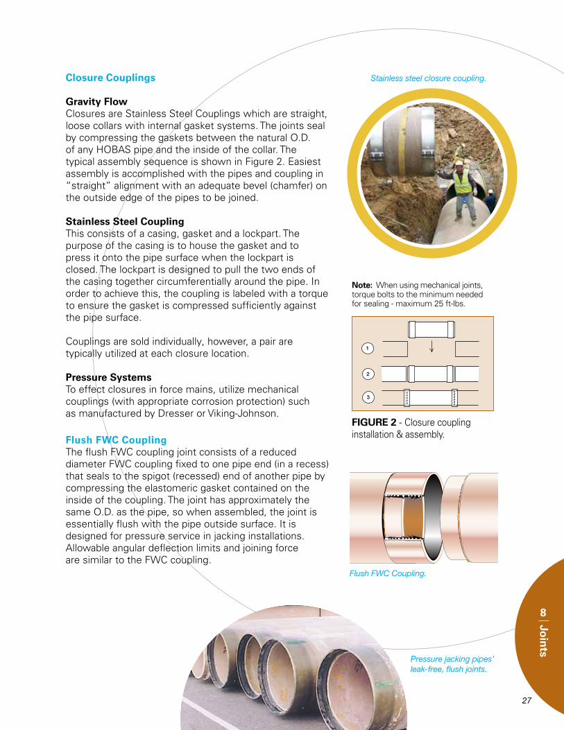
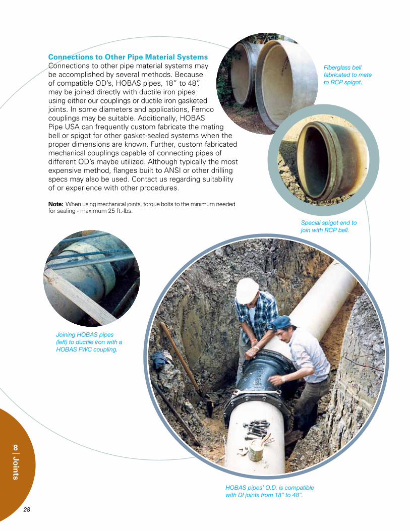
Gravity FlowClosures are Stainless Steel Couplings which are straight, loose collars with internal gasket systems. The joints seal by compressing the gaskets between the natural O.D. of any HOBAS pipe and the inside of the collar. The typical assembly sequence is shown in Figure 2. Easiest assembly is accomplished with the pipes and coupling in “straight” alignment with an adequate bevel (chamfer) on the outside edge of the pipes to be joined.
Stainless Steel CouplingThis consists of a casing, gasket and a lockpart. The purpose of the casing is to house the gasket and to press it onto the pipe surface when the lockpart is closed. The lockpart is designed to pull the two ends of the casing together circumferentially around the pipe. In order to achieve this, the coupling is labeled with a torque to ensure the gasket is compressed sufficiently against the pipe surface.
Couplings are sold individually, however, a pair are typically utilized at each closure location.
Pressure SystemsTo effect closures in force mains, utilize mechanical couplings (with appropriate corrosion protection) such as manufactured by Dresser or Viking-Johnson.
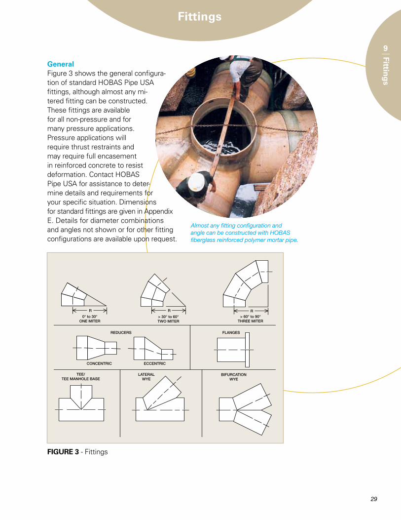
Flush FWC CouplingThe flush FWC coupling joint consists of a reduced diameter FWC coupling fixed to one pipe end (in a recess) that seals to the spigot (recessed) end of another pipe by compressing the elastomeric gasket contained on the inside of the coupling. The joint has approximately the same O.D. as the pipe, so when assembled, the joint is essentially flush with the pipe outside surface. It is designed for pressure service in jacking installations. Allowable angular deflection limits and joining force are similar to the FWC coupling.
Flush FWC Coupling.
Pressure jacking pipes’ leak-free, flush joints.
Stainless steel closure coupling.
FIGURE 2 - Closure coupling installation & assembly.
Note: When using mechanical joints, torque bolts to the minimum needed for sealing - maximum 25 ft-lbs.
28 29
8
Join
ts
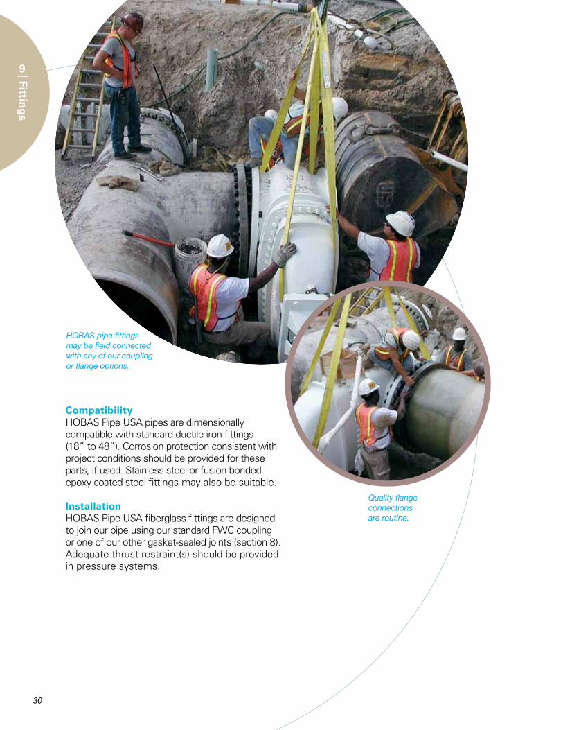
Connections to Other Pipe Material SystemsConnections to other pipe material systems may be accomplished by several methods. Because of compatible OD’s, HOBAS pipes, 18” to 48”, may be joined directly with ductile iron pipes using either our couplings or ductile iron gasketed joints. In some diameters and applications, Fernco couplings may be suitable. Additionally, HOBAS Pipe USA can frequently custom fabricate the mating bell or spigot for other gasket-sealed systems when the proper dimensions are known. Further, custom fabricated mechanical couplings capable of connecting pipes of different OD’s maybe utilized. Although typically the most expensive method, flanges built to ANSI or other drilling specs may also be used. Contact us regarding suitability of or experience with other procedures.
Note: When using mechanical joints, torque bolts to the minimum needed for sealing - maximum 25 ft.-lbs.
HOBAS pipes’ O.D. is compatible with DI joints from 18” to 48”.
Fiberglass bell fabricated to mate to RCP spigot.
Special spigot end to join with RCP bell.
Joining HOBAS pipes (left) to ductile iron with a HOBAS FWC coupling.
29
9
Fitting
sFittings
GeneralFigure 3 shows the general configura-tion of standard HOBAS Pipe USA fittings, although almost any mi-tered fitting can be constructed. These fittings are available for all non-pressure and for many pressure applications. Pressure applications will require thrust restraints and may require full encasement in reinforced concrete to resist deformation. Contact HOBAS Pipe USA for assistance to deter-mine details and requirements for your specific situation. Dimensions for standard fittings are given in Appendix E. Details for diameter combinations and angles not shown or for other fitting configurations are available upon request.
FIGURE 3 - Fittings
Almost any fitting configuration and angle can be constructed with HOBAS fiberglass reinforced polymer mortar pipe.
30
9
Fitting
s
CompatibilityHOBAS Pipe USA pipes are dimensionally compatible with standard ductile iron fittings (18” to 48”). Corrosion protection consistent with project conditions should be provided for these parts, if used. Stainless steel or fusion bonded epoxy-coated steel fittings may also be suitable.
InstallationHOBAS Pipe USA fiberglass fittings are designed to join our pipe using our standard FWC coupling or one of our other gasket-sealed joints (section 8). Adequate thrust restraint(s) should be provided in pressure systems.
HOBAS pipe fittings may be field connected with any of our coupling or flange options.
Quality flange connections are routine.
31
10
Man
ho
les
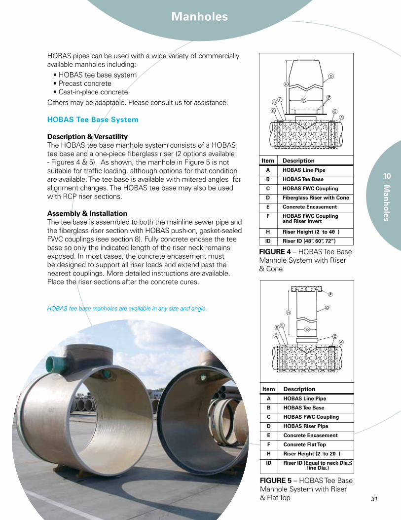
HOBAS pipes can be used with a wide variety of commercially available manholes including:
• HOBAS tee base system• Precast concrete• Cast-in-place concrete
Others may be adaptable. Please consult us for assistance.
HOBAS Tee Base System
Description & VersatilityThe HOBAS tee base manhole system consists of a HOBAS tee base and a one-piece fiberglass riser (2 options available - Figures 4 & 5). As shown, the manhole in Figure 5 is not suitable for traffic loading, although options for that condition are available. The tee base is available with mitered angles for alignment changes. The HOBAS tee base may also be used with RCP riser sections.
Assembly & InstallationThe tee base is assembled to both the mainline sewer pipe and the fiberglass riser section with HOBAS push-on, gasket-sealed FWC couplings (see section 8). Fully concrete encase the tee base so only the indicated length of the riser neck remains exposed. In most cases, the concrete encasement must be designed to support all riser loads and extend past the nearest couplings. More detailed instructions are available. Place the riser sections after the concrete cures.
HOBAS tee base manholes are available in any size and angle.
FIGURE 4 – HOBAS Tee Base Manhole System with Riser & Cone
Item Description
A HOBAS Line Pipe
B HOBAS Tee Base
C HOBAS FWC Coupling
D Fiberglass Riser with Cone
E Concrete Encasement
F HOBAS FWC Coupling and Riser Invert
H Riser Height (2 to 40 )
ID Riser ID (48”, 60”, 72”)
FIGURE 5 – HOBAS Tee Base Manhole System with Riser & Flat Top
Item Description
A HOBAS Line Pipe
B HOBAS Tee Base
C HOBAS FWC Coupling
D HOBAS Riser Pipe
E Concrete Encasement
F Concrete Flat Top
H Riser Height (2 to 20 )
ID Riser ID (Equal to neck Dia.≤ line Dia.)
Manholes
32
10
Man
ho
les
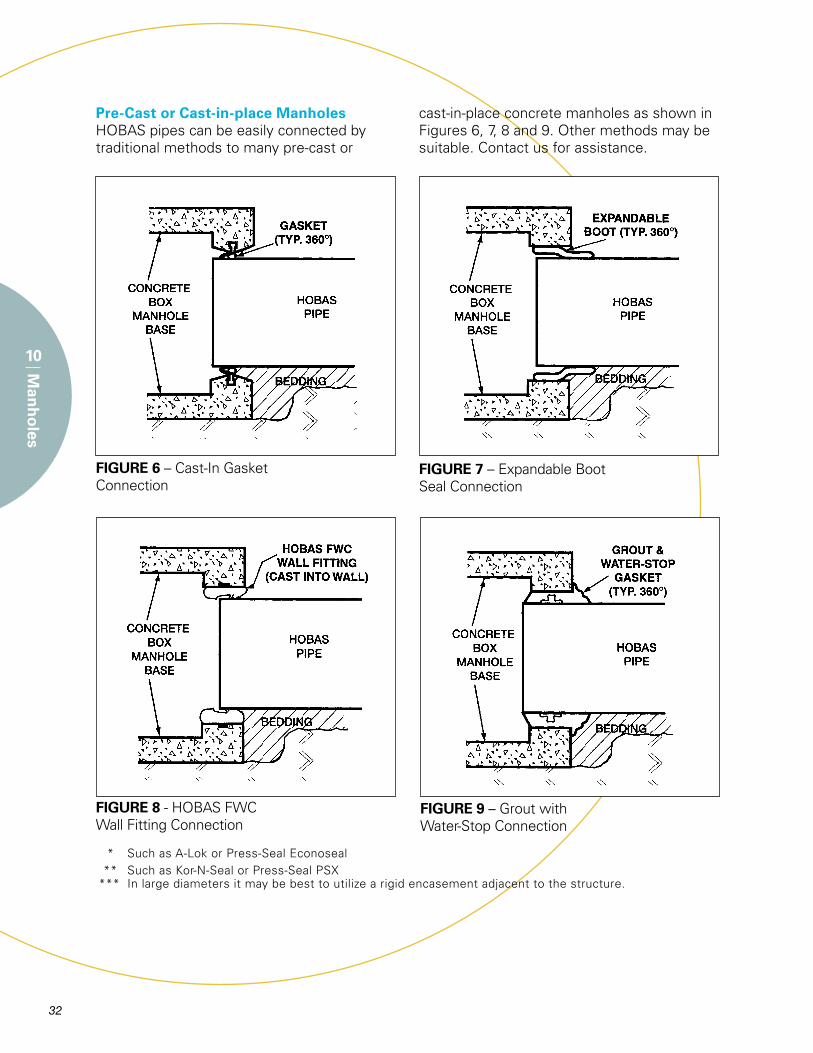
Pre-Cast or Cast-in-place ManholesHOBAS pipes can be easily connected by traditional methods to many pre-cast or
cast-in-place concrete manholes as shown in Figures 6, 7, 8 and 9. Other methods may be suitable. Contact us for assistance.
* Such as A-Lok or Press-Seal Econoseal
** Such as Kor-N-Seal or Press-Seal PSX
*** In large diameters it may be best to utilize a rigid encasement adjacent to the structure.
FIGURE 6 – Cast-In Gasket Connection
FIGURE 8 - HOBAS FWC Wall Fitting Connection
FIGURE 7 – Expandable Boot Seal Connection
FIGURE 9 – Grout with Water-Stop Connection
32 33
Pipe ManufacturingProcess
11
Pip
e Man
ufactu
ring
Pro
cess
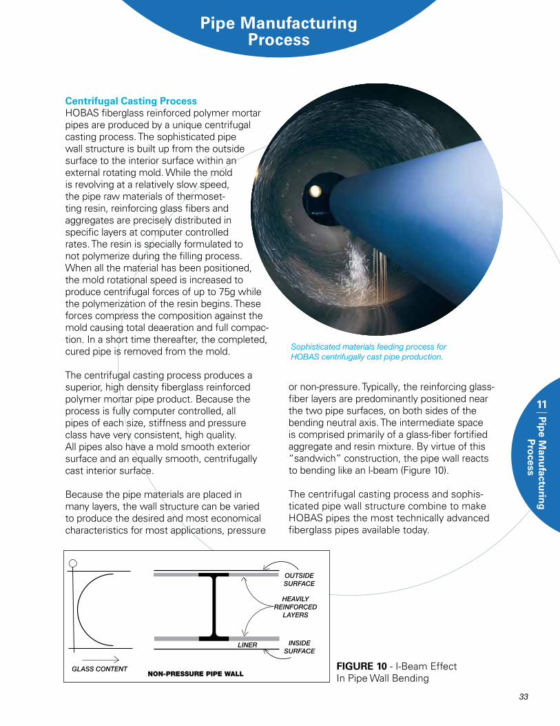
Centrifugal Casting ProcessHOBAS fiberglass reinforced polymer mortar pipes are produced by a unique centrifugal casting process. The sophisticated pipe wall structure is built up from the outside surface to the interior surface within an external rotating mold. While the mold is revolving at a relatively slow speed, the pipe raw materials of thermoset-ting resin, reinforcing glass fibers and aggregates are precisely distributed in specific layers at computer controlled rates. The resin is specially formulated to not polymerize during the filling process. When all the material has been positioned, the mold rotational speed is increased to produce centrifugal forces of up to 75g while the polymerization of the resin begins. These forces compress the composition against the mold causing total deaeration and full compac-tion. In a short time thereafter, the completed, cured pipe is removed from the mold.
The centrifugal casting process produces a superior, high density fiberglass reinforced polymer mortar pipe product. Because the process is fully computer controlled, all pipes of each size, stiffness and pressure class have very consistent, high quality. All pipes also have a mold smooth exterior surface and an equally smooth, centrifugally cast interior surface.
Because the pipe materials are placed in many layers, the wall structure can be varied to produce the desired and most economical characteristics for most applications, pressure
or non-pressure. Typically, the reinforcing glass-fiber layers are predominantly positioned near the two pipe surfaces, on both sides of the bending neutral axis. The intermediate space is comprised primarily of a glass-fiber fortified aggregate and resin mixture. By virtue of this “sandwich” construction, the pipe wall reacts to bending like an l-beam (Figure 10).
The centrifugal casting process and sophis-ticated pipe wall structure combine to make HOBAS pipes the most technically advanced fiberglass pipes available today.
FIGURE 10 - I-Beam Effect In Pipe Wall Bending
Sophisticated materials feeding process for HOBAS centrifugally cast pipe production.
34
Pip
e M
anu
facturin
g P
rocess
11
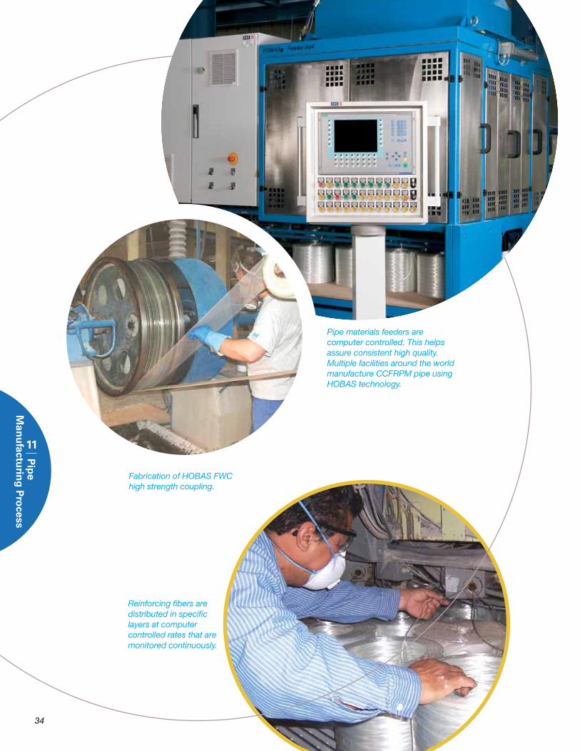
Pipe materials feeders are computer controlled. This helps assure consistent high quality. Multiple facilities around the world manufacture CCFRPM pipe using HOBAS technology.
Fabrication of HOBAS FWChigh strength coupling.
Reinforcing fibers are distributed in specific layers at computer controlled rates that are monitored continuously.
34 35
12
Qu
ality Co
ntro
lQuality Control
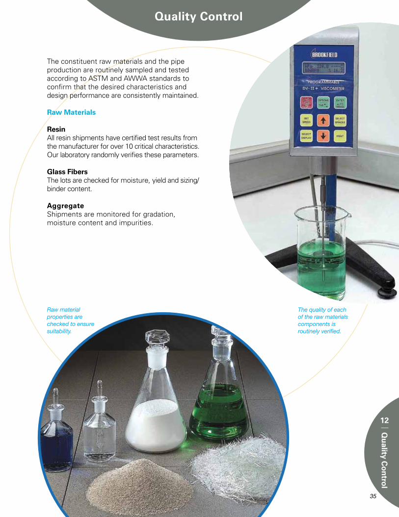
The constituent raw materials and the pipe production are routinely sampled and tested according to ASTM and AWWA standards to confirm that the desired characteristics and design performance are consistently maintained.
Raw Materials
ResinAll resin shipments have certified test results from the manufacturer for over 10 critical characteristics. Our laboratory randomly verifies these parameters.
Glass FibersThe lots are checked for moisture, yield and sizing/binder content.
AggregateShipments are monitored for gradation, moisture content and impurities.
The quality of each of the raw materials components is routinely verified.
Raw material properties are checked to ensure suitability.
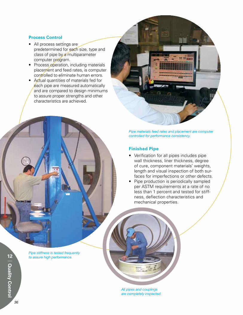
Process Control
• All process settings are predetermined for each size, type and
class of pipe by a multiparameter computer program.
• Process operation, including materials placement and feed rates, is computer controlled to eliminate human errors.
• Actual quantities of materials fed for each pipe are measured automatically and are compared to design minimums to assure proper strengths and other characteristics are achieved.
Finished Pipe
• Verification for all pipes includes pipe wall thickness, liner thickness, degree of cure, component materials’ weights, length and visual inspection of both sur-faces for imperfections or other defects.
• Pipe production is periodically sampled per ASTM requirements at a rate of no less than 1 percent and tested for stiff-ness, deflection characteristics and mechanical properties.
Pipe materials feed rates and placement are computer controlled for performance consistency.
Pipe stiffness is tested frequently to assure high performance.
All pipes and couplings are completely inspected.
36
12
Qu
ality Co
ntro
l
37
13
Stan
dard
sStandards
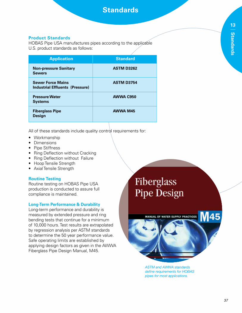
ASTM and AWWA standards define requirements for HOBAS pipes for most applications.
Product StandardsHOBAS Pipe USA manufactures pipes according to the applicable U.S. product standards as follows:
Application Standard
Non-pressure Sanitary ASTM D3262 Sewers
Sewer Force Mains ASTM D3754 Industrial Effluents (Pressure)
Pressure Water AWWA C950 Systems
Fiberglass Pipe AWWA M45 Design
All of these standards include quality control requirements for:
• Workmanship• Dimensions• Pipe Stiffness• Ring Deflection without Cracking• Ring Deflection without Failure• Hoop Tensile Strength• Axial Tensile Strength
Routine TestingRoutine testing on HOBAS Pipe USA production is conducted to assure full compliance is maintained.
Long-Term Performance & DurabilityLong-term performance and durability is measured by extended pressure and ring bending tests that continue for a minimum of 10,000 hours. Test results are extrapolated by regression analysis per ASTM standards to determine the 50 year performance value. Safe operating limits are established by applying design factors as given in the AWWA Fiberglass Pipe Design Manual, M45.
38
ASTM D638 Tensile Properties by Coupon
ASTM D3567 Dimensions
ASTM D2992 HDB Procedure
ASTM D2584 Composition by Loss on Ignition
ASTM D2583 Barcol Hardness (cure)
ASTM D2412 Pipe Stiffness
ASTM D2290 Tensile Strength by Split Disk
ASTM D1599 Quick Burst
ASTM D790 Flexural Properties by Coupon
ASTM D3681 Chemical Resistance - Deflected
Test
Designation Purpose
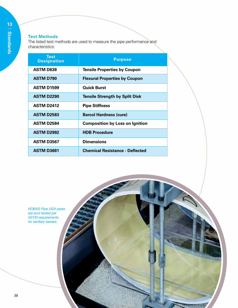
HOBAS Pipe USA pipes are acid tested per ASTM requirements for sanitary sewers.
Test MethodsThe listed test methods are used to measure the pipe performance and characteristics:
13
Stan
dard
s
39
14
Installatio
nInstallation
A Direct BuryA1 Trench Construction
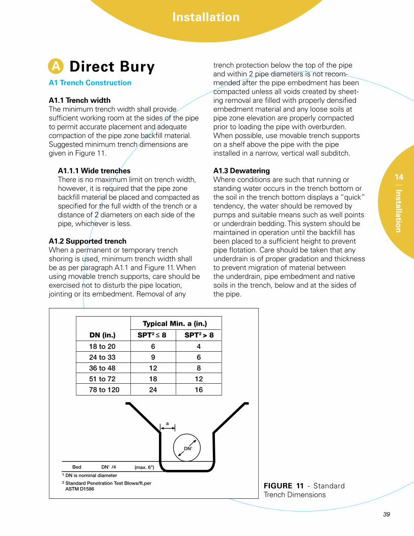
A1.1 Trench width The minimum trench width shall provide sufficient working room at the sides of the pipe to permit accurate placement and adequate compaction of the pipe zone backfill material. Suggested minimum trench dimensions are given in Figure 11.
A1.1.1 Wide trenchesThere is no maximum limit on trench width, however, it is required that the pipe zone backfill material be placed and compacted as specified for the full width of the trench or a distance of 2 diameters on each side of the pipe, whichever is less.
A1.2 Supported trenchWhen a permanent or temporary trench shoring is used, minimum trench width shall be as per paragraph A1.1 and Figure 11. When using movable trench supports, care should be exercised not to disturb the pipe location, jointing or its embedment. Removal of any
trench protection below the top of the pipe and within 2 pipe diameters is not recom-mended after the pipe embedment has been compacted unless all voids created by sheet-ing removal are filled with properly densified embedment material and any loose soils at pipe zone elevation are properly compacted prior to loading the pipe with overburden. When possible, use movable trench supports on a shelf above the pipe with the pipe installed in a narrow, vertical wall subditch.
A1.3 Dewatering Where conditions are such that running or standing water occurs in the trench bottom or the soil in the trench bottom displays a “quick” tendency, the water should be removed by pumps and suitable means such as well points or underdrain bedding. This system should be maintained in operation until the backfill has been placed to a sufficient height to prevent pipe flotation. Care should be taken that any underdrain is of proper gradation and thickness to prevent migration of material between the underdrain, pipe embedment and native soils in the trench, below and at the sides of the pipe.
FIGURE 11 - Standard Trench Dimensions
Typical Min. a (in.)
DN (in.) SPT2 ≤ 8 SPT2 > 8
18to20 6 4
24to33 9 6
36to48 12 8
51to72 18 12
78to120 24 16
40
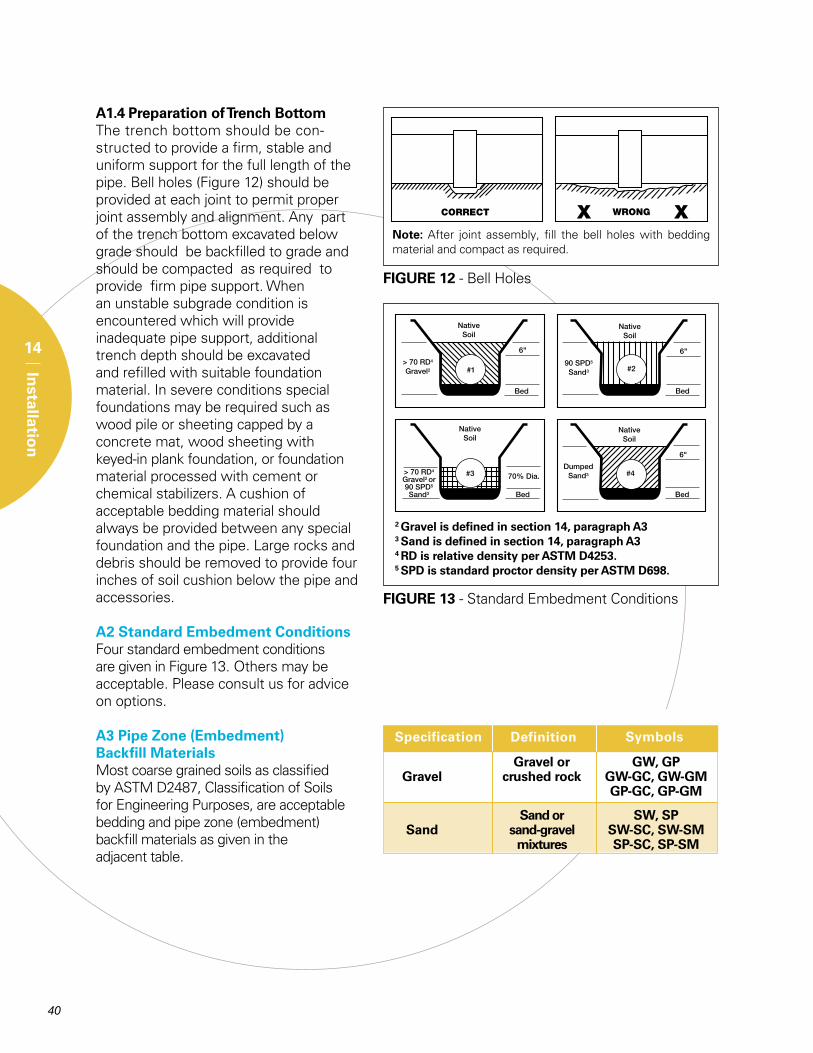
A1.4 Preparation of Trench BottomThe trench bottom should be con-structed to provide a firm, stable and uniform support for the full length of the pipe. Bell holes (Figure 12) should be provided at each joint to permit proper joint assembly and alignment. Any part of the trench bottom excavated below grade should be backfilled to grade and should be compacted as required to provide firm pipe support. When an unstable subgrade condition is encountered which will provide inadequate pipe support, additional trench depth should be excavated and refilled with suitable foundation material. In severe conditions special foundations may be required such as wood pile or sheeting capped by a concrete mat, wood sheeting with keyed-in plank foundation, or foundation material processed with cement or chemical stabilizers. A cushion of acceptable bedding material should always be provided between any special foundation and the pipe. Large rocks and debris should be removed to provide four inches of soil cushion below the pipe and accessories.
A2 Standard Embedment ConditionsFour standard embedment conditions are given in Figure 13. Others may be acceptable. Please consult us for advice on options.
A3 Pipe Zone (Embedment) Backfill MaterialsMost coarse grained soils as classified by ASTM D2487, Classification of Soils for Engineering Purposes, are acceptable bedding and pipe zone (embedment) backfill materials as given in the adjacent table.
FIGURE 12 - Bell Holes
Note: After joint assembly, fill the bell holes with bedding material and compact as required.
FIGURE 13 - Standard Embedment Conditions
2 Gravel is defined in section 14, paragraph A33 Sand is defined in section 14, paragraph A34 RD is relative density per ASTM D4253.5 SPD is standard proctor density per ASTM D698.
Specification Definition
Gravel or GW, GP Gravel crushed rock GW-GC, GW-GM GP-GC, GP-GM
Sand or SW, SP Sand sand-gravel SW-SC, SW-SM mixtures SP-SC, SP-SM
Symbols
14
Installatio
n
41
Maximum grain size should typically not exceed 1 to 11/2 times the pipe wall thick-ness or 11/2 inches whichever is smaller.
Well graded materials that will minimize voids in the embedment materials should be used in cases where migration of fines in the trench wall material into the embed-ment can be anticipated. Alternatively, separate the open graded material from the non-cohesive soil with a filter fabric to prevent migration of the smaller grained soil into the open graded material. Such migration is undesirable since it would reduce the soil density near the pipe zone and thereby lessen the pipe support.
Embedment materials should contain no debris, foreign or frozen materials.
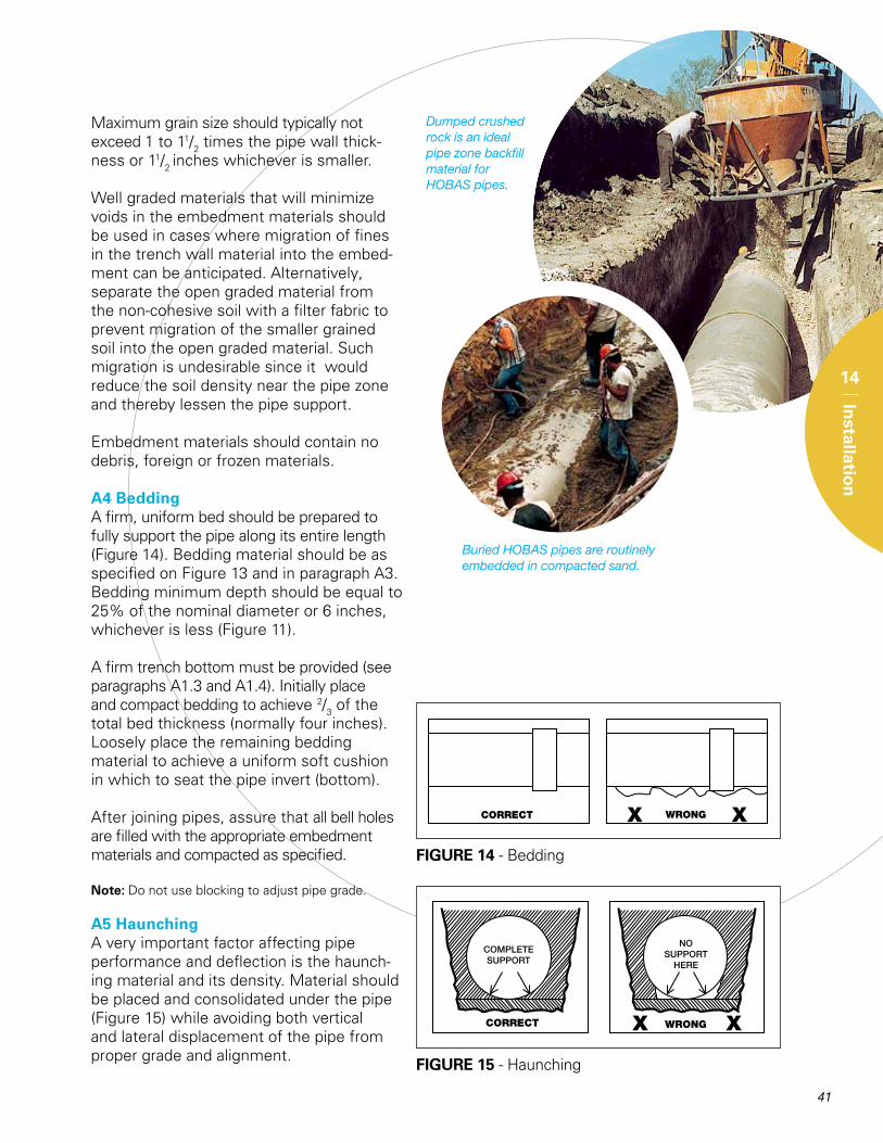
A4 BeddingA firm, uniform bed should be prepared to fully support the pipe along its entire length (Figure 14). Bedding material should be as specified on Figure 13 and in paragraph A3. Bedding minimum depth should be equal to 25% of the nominal diameter or 6 inches, whichever is less (Figure 11).
A firm trench bottom must be provided (see paragraphs A1.3 and A1.4). Initially place and compact bedding to achieve 2/3 of the total bed thickness (normally four inches). Loosely place the remaining bedding material to achieve a uniform soft cushion in which to seat the pipe invert (bottom).
After joining pipes, assure that all bell holes are filled with the appropriate embedment materials and compacted as specified.
Note: Do not use blocking to adjust pipe grade.
A5 HaunchingA very important factor affecting pipe performance and deflection is the haunch-ing material and its density. Material should be placed and consolidated under the pipe (Figure 15) while avoiding both vertical and lateral displacement of the pipe from proper grade and alignment.
FIGURE 14 - Bedding
FIGURE 15 - Haunching
Dumped crushed rock is an ideal pipe zone backfill material for HOBAS pipes.
Buried HOBAS pipes are routinely embedded in compacted sand.
14
Installatio
n
42
14
Installatio
n
A6 BackfillingPipe zone (embedment) material shall be as specified on Figure 13 and in paragraph A3. (It must be the same as the bedding material to prevent potential migration.)
Place and compact the embedment material in lifts to achieve the depths and densities specified on Figure 13. Little or no tamping of the initial backfill directly over the top of the pipe should be done to avoid disturbing the embedded pipe.
Remaining backfill may be the native trench material provided clumps and boulders larger than 3 to 4 inches in size are not used until 12 inches of pipe cover has been achieved.
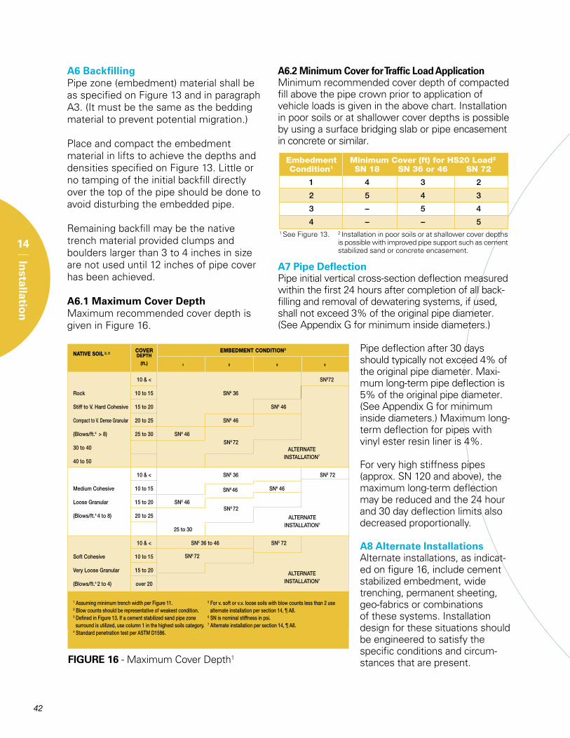
A6.1 Maximum Cover Depth Maximum recommended cover depth is given in Figure 16.
A6.2 Minimum Cover for Traffic Load Application Minimum recommended cover depth of compacted fill above the pipe crown prior to application of vehicle loads is given in the above chart. Installation in poor soils or at shallower cover depths is possible by using a surface bridging slab or pipe encasement in concrete or similar.
A7 Pipe DeflectionPipe initial vertical cross-section deflection measured within the first 24 hours after completion of all back-filling and removal of dewatering systems, if used, shall not exceed 3% of the original pipe diameter. (See Appendix G for minimum inside diameters.)
Pipe deflection after 30 days should typically not exceed 4% of the original pipe diameter. Maxi-mum long-term pipe deflection is 5% of the original pipe diameter. (See Appendix G for minimum inside diameters.) Maximum long-term deflection for pipes with vinyl ester resin liner is 4%.
For very high stiffness pipes (approx. SN 120 and above), the maximum long-term deflection may be reduced and the 24 hour and 30 day deflection limits also decreased proportionally.
A8 Alternate InstallationsAlternate installations, as indicat-ed on figure 16, include cement stabilized embedment, wide trenching, permanent sheeting, geo-fabrics or combinations of these systems. Installation design for these situations should be engineered to satisfy the specific conditions and circum-stances that are present.FIGURE 16 - Maximum Cover Depth1
ALternAteInstALLAtIon7
ALternAteInstALLAtIon7
ALternAteInstALLAtIon7
sn672
sn672
sn672
sn646
NATIVE SOIL 2, 5 COVER EMBEDMENT CONDITION3
DEPTH
(ft.) 1 2 3 4
10&< sn672
rock 10to15 sn636
stifftoV.HardCohesive 15to20 sn646
CompacttoV.DenseGranular 20to25 sn646
(Blows/ft.4>8) 25to30 sn646
30to40
40to50
10&< sn636 sn672
MediumCohesive 10to15 sn646
LooseGranular 15to20 sn646
(Blows/ft.44to8) 20to25
25to30
10&< sn636to46 sn672
softCohesive 10to15
VeryLooseGranular 15to20
(Blows/ft.42to4) over20
1AssumingminimumtrenchwidthperFigure11. 5Forv.softorv.v.loosesoilswithblowcountslessthan2use2Blowcountsshouldberepresentativeofweakestcondition. alternateinstallationpersection14,¶A8.3DefinedinFigure13.Ifacementstabilizedsandpipezone 6snisnominalstiffnessinpsi.surroundisutilized,usecolumn1inthehighestsoilscategory. 7Alternateinstallationpersection14,¶A8.4standardpenetrationtestperAstMD1586.
1 See Figure 13. 2 Installation in poor soils or at shallower cover depths is possible with improved pipe support such as cement stabilized sand or concrete encasement.
Embedment Minimum Cover (ft) for HS20 Load2
Condition1 SN 18 SN 36 or 46 SN 72
1 4 3 2
2 5 4 3
3 – 5 4
4 – – 5
43
14
Installatio
n
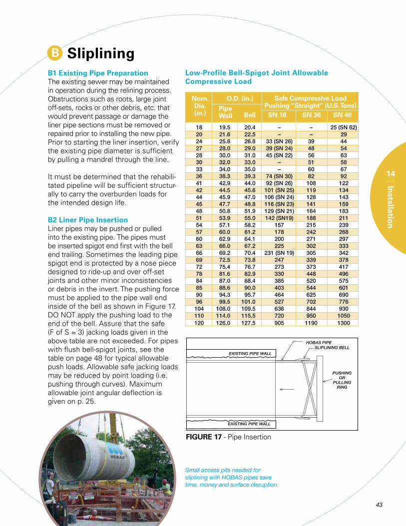
B SlipliningB1 Existing Pipe PreparationThe existing sewer may be maintained in operation during the relining process. Obstructions such as roots, large joint off-sets, rocks or other debris, etc. that would prevent passage or damage the liner pipe sections must be removed or repaired prior to installing the new pipe. Prior to starting the liner insertion, verify the existing pipe diameter is sufficient by pulling a mandrel through the line.
It must be determined that the rehabili-tated pipeline will be sufficient structur-ally to carry the overburden loads for the intended design life.
B2 Liner Pipe InsertionLiner pipes may be pushed or pulled into the existing pipe. The pipes must be inserted spigot end first with the bell end trailing. Sometimes the leading pipe spigot end is protected by a nose piece designed to ride-up and over off-set joints and other minor inconsistencies or debris in the invert. The pushing force must be applied to the pipe wall end inside of the bell as shown in Figure 17. DO NOT apply the pushing load to the end of the bell. Assure that the safe (F of S ≈ 3) jacking loads given in the above table are not exceeded. For pipes with flush bell-spigot joints, see the table on page 48 for typical allowable push loads. Allowable safe jacking loads may be reduced by point loading (i.e. pushing through curves). Maximum allowable joint angular deflection is given on p. 25.
FIGURE 17 - Pipe Insertion
Nom. Dia. (in.)
O.D. (in.)
PipeWall Bell
Safe Compressive LoadPushing “Straight” (U.S. Tons)SN 18 SN 36 SN 46
Low-Profile Bell-Spigot Joint Allowable Compressive Load
Small access pits needed for sliplining with HOBAS pipes save time, money and surface disruption.
18 19.5 20.4 – – 25(sn62) 20 21.6 22.5 – – 29 24 25.8 26.8 33(sn26) 39 44 27 28.0 29.0 39(sn24) 48 54 28 30.0 31.0 45(sn22) 56 63 30 32.0 33.0 – 51 58 33 34.0 35.0 – 60 67 36 38.3 39.3 74(sn30) 82 92 41 42.9 44.0 92(sn26) 108 122 42 44.5 45.6 101(sn25) 119 134 44 45.9 47.0 106(sn24) 128 143 45 47.7 48.8 116(sn23) 141 159 48 50.8 51.9 129(sn21) 164 183 51 53.9 55.0 142(sn19) 188 211 54 57.1 58.2 157 215 239 57 60.0 61.2 178 242 268 60 62.9 64.1 200 271 297 63 66.0 67.2 225 302 333 66 69.2 70.4 231(sn19) 305 342 69 72.5 73.8 247 339 378 72 75.4 76.7 273 373 417 78 81.6 82.9 330 448 496 84 87.0 88.4 385 520 575 85 88.6 90.0 403 544 601 90 94.3 95.7 464 625 690 96 99.5 101.0 527 702 776 104 108.0 109.5 636 844 930 110 114.0 115.5 720 950 1050 120 126.0 127.5 905 1190 1300
44 45
14
Installatio
n
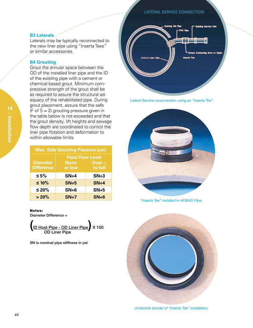
B3 LateralsLaterals may be typically reconnected to the new liner pipe using “Inserta Tees” or similar accessories. B4 GroutingGrout the annular space between the OD of the installed liner pipe and the ID of the existing pipe with a cement or chemical based grout. Minimum com-pressive strength of the grout shall be as required to assure the structural ad-equacy of the rehabilitated pipe. During grout placement, assure that the safe (F of S ≈ 2) grouting pressure given in the table below is not exceeded and that the grout density, lift heights and sewage flow depth are coordinated to control the liner pipe flotation and deformation to within allowable limits.
Notes:DiameterDifference=
(IDHostPipe-oDLinerPipe)X100 oDLinerPipe
snisnominalpipestiffnessinpsi
DiameterDifference
Fluid Flow Level
Max. Safe Grouting Pressure (psi)
None Over 1/2
or low to full
≤ 5% SN÷4 SN÷3
≤ 10% SN÷5 SN÷4
≤ 20% SN÷6 SN÷5
> 20% SN÷7 SN÷6
Lateral Service reconnection using an “Inserta Tee”.
Underside (inside) of “Inserta Tee” installation.
“Inserta Tee” installed in HOBAS Pipe.
45
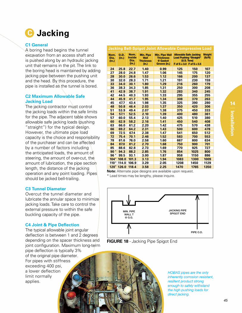
C JackingC1 GeneralA boring head begins the tunnel excavation from an access shaft and is pushed along by an hydraulic jacking unit that remains in the pit. The link to the boring head is maintained by adding jacking pipe between the pushing unit and the head. By this procedure, the pipe is installed as the tunnel is bored.
C2 Maximum Allowable Safe Jacking LoadThe jacking contractor must control the jacking loads within the safe limits for the pipe. The adjacent table shows allowable safe jacking loads (pushing “straight”) for the typical design. However, the ultimate pipe load capacity is the choice and responsibility of the purchaser and can be affected by a number of factors including the anticipated loads, the amount of steering, the amount of over-cut, the amount of lubrication, the pipe section length, the distance of the jacking operation and any point loading. Pipes should be jacked bell-trailing.
C3 Tunnel DiameterOvercut the tunnel diameter and lubricate the annular space to minimize jacking loads. Take care to control the external pressure to within the safe buckling capacity of the pipe.
C4 Joint & Pipe DeflectionThe typical allowable joint angular deflection is between 1 and 2 degrees depending on the spacer thickness and joint configuration. Maximum long-term pipe deflection is typically 3% of the original pipe diameter. For pipes with stiffness exceeding 400 psi, a lower deflection limit normally applies.
FIGURE 18 - Jacking Pipe Spigot End
HOBAS pipes are the only inherently corrosion resistant, resilient product strong enough to safely withstand the high pushing loads for direct jacking.
14
Installatio
n
* Lead times may be lengthy, please inquire.Note: Alternate pipe designs are available upon request.
Allowable Safe Jacking Load Pushing “Straight”
(U.S. Tons)F of S = 3.0
Min. Pipe Wall Thickness @ Gasket
Groove (in.)
Nom. Dia.(in.)
O.D.(in.)
Nom. InsideDia.(in.)
Min. Pipe Wall
Thickness (in.)
Weight (lb/ft)
*****
F of S = 2.5
Jacking Bell-Spigot Joint Allowable Compressive Load
24 25.8 22.7 1.40 0.99 125 150 107 27 28.0 24.8 1.47 1.06 145 175 120 28 30.0 26.6 1.53 1.12 166 200 137 30 32.0 28.3 1.71 1.21 191 230 159 33 34.0 30.1 1.80 1.29 216 260 179 36 38.3 34.3 1.85 1.31 250 300 208 41 42.9 38.7 1.91 1.32 283 340 245 42 44.5 40.3 1.93 1.33 295 355 255 44 45.9 41.7 1.95 1.34 308 370 263 45 47.7 43.4 1.98 1.35 325 390 280 48 50.8 46.4 2.03 1.37 350 420 306 51 53.9 49.4 2.07 1.38 375 450 333 54 57.1 52.5 2.10 1.39 400 480 361 57 60.0 55.4 2.13 1.40 425 510 380 60 62.9 58.2 2.16 1.41 450 540 408 63 66.0 61.2 2.20 1.42 475 570 438 66 69.2 64.2 2.31 1.43 500 600 478 69 72.5 67.4 2.38 1.47 541 650 512 72 75.4 70.1 2.46 1.52 583 700 553 78 81.6 76.0 2.58 1.60 667 800 634 84 87.0 81.2 2.70 1.68 750 900 701 85 88.6 82.8 2.73 1.69 770 925 727 90 94.3 88.2 2.85 1.76 854 1025 800 96 99.5 93.1 3.00 1.87 958 1150 886 104 108.0 101.3 3.13 1.94 1083 1300 1009 110 114.0 106.9 3.29 2.05 1208 1450 1129 120 126.0 118.4 3.58 2.25 1470 1765 1350
46
14
Installatio
n
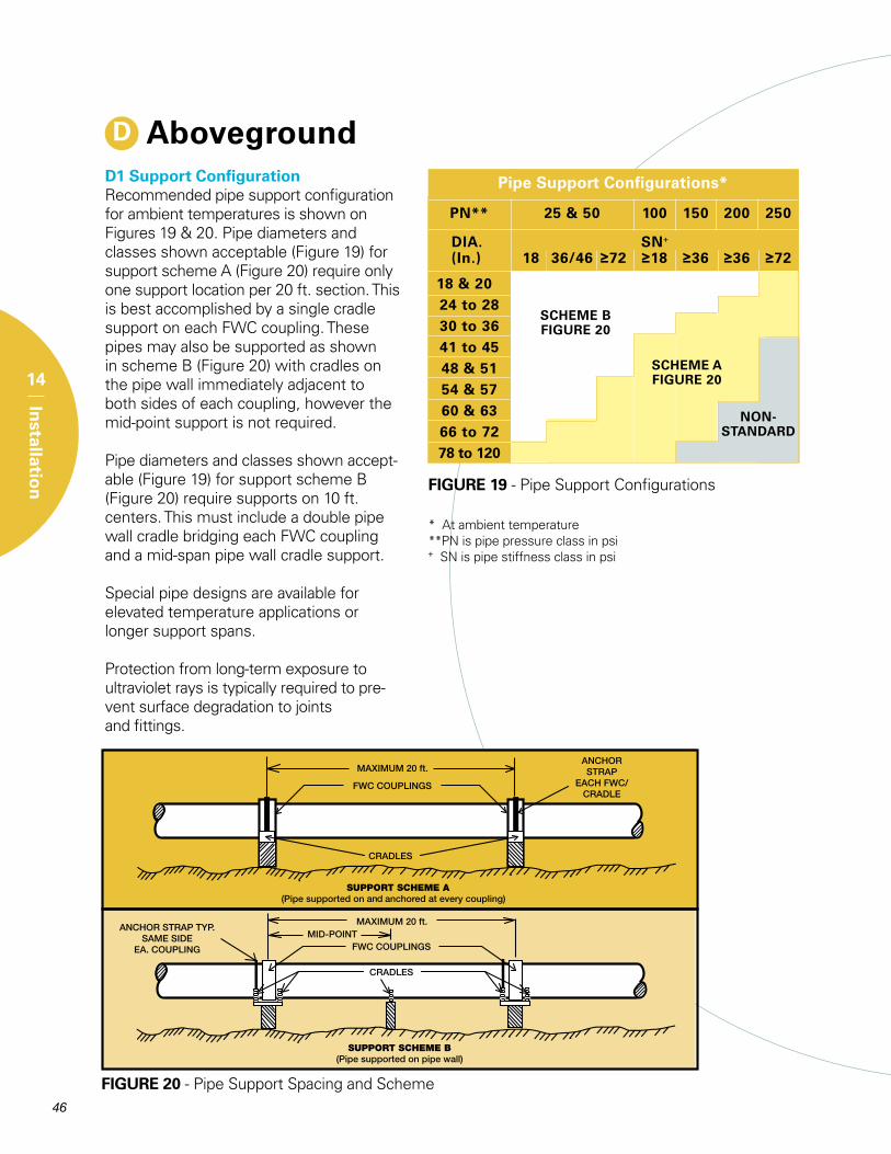
D AbovegroundD1 Support ConfigurationRecommended pipe support configuration for ambient temperatures is shown on Figures 19 & 20. Pipe diameters and classes shown acceptable (Figure 19) for support scheme A (Figure 20) require only one support location per 20 ft. section. This is best accomplished by a single cradle support on each FWC coupling. These pipes may also be supported as shown in scheme B (Figure 20) with cradles on the pipe wall immediately adjacent to both sides of each coupling, however the mid-point support is not required.
Pipe diameters and classes shown accept-able (Figure 19) for support scheme B (Figure 20) require supports on 10 ft. centers. This must include a double pipe wall cradle bridging each FWC coupling and a mid-span pipe wall cradle support.
Special pipe designs are available for elevated temperature applications or longer support spans.
Protection from long-term exposure to ultraviolet rays is typically required to pre-vent surface degradation to joints and fittings.
FIGURE 20 - Pipe Support Spacing and Scheme
* At ambient temperature**PN is pipe pressure class in psi+ SN is pipe stiffness class in psi
FIGURE 19 - Pipe Support Configurations
NON-STANDARD
SCHEME AFIGURE 20
SCHEME BFIGURE 20
PN** 25 & 50 100 150 200 250
DIA. SN+ (In.) 18 36/46 ≥72 ≥18 ≥36 ≥36 ≥72 18 & 20 24 to 28 30 to 36 41 to 45 48 & 51 54 & 57 60 & 63 66 to 72 78 to 120
Pipe Support Configurations*
47
14
Installatio
n
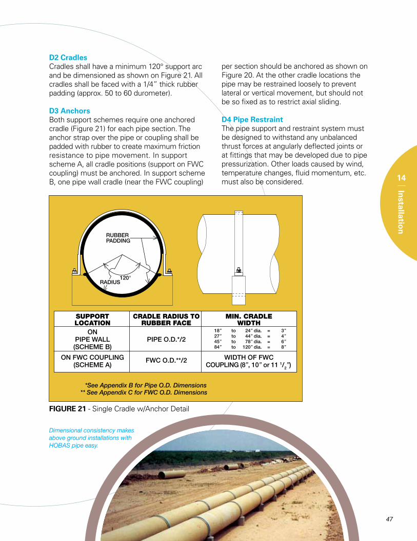
D2 CradlesCradles shall have a minimum 120° support arc and be dimensioned as shown on Figure 21. All cradles shall be faced with a 1/4” thick rubber padding (approx. 50 to 60 durometer).
D3 AnchorsBoth support schemes require one anchored cradle (Figure 21) for each pipe section. The anchor strap over the pipe or coupling shall be padded with rubber to create maximum friction resistance to pipe movement. In support scheme A, all cradle positions (support on FWC coupling) must be anchored. In support scheme B, one pipe wall cradle (near the FWC coupling)
FIGURE 21 - Single Cradle w/Anchor Detail
SUPPORT CRADLERADIUSTO MIN.CRADLE LOCATION RUBBERFACE WIDTH on PIPeWALL PIPeo.D.*/2 (sCHeMeB)
onFWCCoUPLInG WIDtHoFFWC (sCHeMeA)
FWCo.D.**/2 CoUPLInG(8”,10”or111/2”)
18” to 24”dia. = 3”27” to 44”dia. = 4”45” to 78”dia. = 6”84” to 120”dia. = 8”
per section should be anchored as shown on Figure 20. At the other cradle locations the pipe may be restrained loosely to prevent lateral or vertical movement, but should not be so fixed as to restrict axial sliding.
D4 Pipe RestraintThe pipe support and restraint system must be designed to withstand any unbalanced thrust forces at angularly deflected joints or at fittings that may be developed due to pipe pressurization. Other loads caused by wind, temperature changes, fluid momentum, etc. must also be considered.
Dimensional consistency makes above ground installations with HOBAS pipe easy.
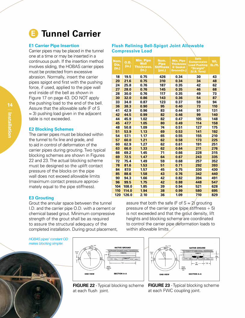
E Tunnel CarrierE1 Carrier Pipe InsertionCarrier pipes may be placed in the tunnel one at a time or may be inserted in a continuous push. If the insertion method involves sliding, the HOBAS carrier pipes must be protected from excessive abrasion. Normally, insert the carrier pipes spigot end first with the pushing force, if used, applied to the pipe wall end inside of the bell as shown in Figure 17 on page 43. DO NOT apply the pushing load to the end of the bell. Assure that the allowable safe (F of S ≈ 3) pushing load given in the adjacent table is not exceeded.
E2 Blocking SchemesThe carrier pipes must be blocked within the tunnel to fix line and grade, and to aid in control of deformation of the carrier pipes during grouting. Two typical blocking schemes are shown in Figures 22 and 23. The actual blocking scheme must be designed so the uplift contact pressure of the blocks on the pipe wall does not exceed allowable limits (maximum contact pressure approxi-mately equal to the pipe stiffness).
48
14
Installatio
n
Flush Relining Bell-Spigot Joint Allowable Compressive Load
18 19.5 0.75 426 0.34 30 43 20 21.6 0.75 310 0.34 34 48 24 25.8 0.76 187 0.35 42 62 27 28.0 0.76 145 0.35 46 68 28 30.0 0.76 117 0.35 49 73 30 32.0 0.86 143 0.36 54 87 33 34.0 0.87 123 0.37 59 94 36 38.3 0.90 95 0.40 73 110 41 42.9 0.96 83 0.44 91 131 42 44.5 0.99 82 0.46 99 140 44 45.9 1.02 82 0.47 105 148 45 47.7 1.05 80 0.49 114 158 48 50.8 1.09 74 0.51 127 175 51 53.9 1.13 69 0.53 141 192 54 57.1 1.17 65 0.55 155 210 57 60.0 1.21 62 0.58 173 225 60 62.9 1.27 62 0.61 191 251 63 66.0 1.33 62 0.64 211 276 66 69.2 1.45 71 0.66 228 315 69 72.5 1.47 64 0.67 243 335 72 75.4 1.49 59 0.68 257 352 78 81.6 1.53 51 0.71 292 393 84 87.0 1.57 45 0.75 330 430 85 88.6 1.58 43 0.76 342 440 90 94.3 1.66 42 0.82 394 491 96 99.5 1.75 42 0.88 448 547 104 108.0 1.85 39 0.94 521 628 110 114.0 1.94 38 0.99 580 695 120 126.0 2.10 36 1.09 710 829
Safe Compressive Load Pushing
“Straight” (U.S. Tons)
Min. Pipe Thickness @ Gasket
Groove(in.)
Min. Pipe Wall
Thickness.(in.)
O.D.(in.)
Nom. Dia.(in.)
Nom.Pipe
Stiffness(psi.)
Wt.lb./ft.
E3 GroutingGrout the annular space between the tunnel I.D. and the carrier pipe O.D. with a cement or chemical based grout. Minimum compressive strength of the grout shall be as required to assure the structural adequacy of the completed installation. During grout placement,
assure that both the safe (F of S ≈ 2) grouting pressure of the carrier pipe (pipe stiffness ÷ 5) is not exceeded and that the grout density, lift heights and blocking scheme are coordinated to control the carrier pipe deformation loads to within allowable limits.
FIGURE 22 - Typical blocking scheme at each flush joint.
FIGURE 23 - Typical blocking scheme at each FWC coupling joint.
HOBAS pipes’ constant OD makes blocking simpler.
A
Ap
pen
dix
49
Appendix AGuide Specifications
CCFRPM Pipe for Direct Bury Installation - Gravity ServicePart I General
1.01 Section IncludesA. CentrifugallyCastFiberglassreinforced
PolymerMortarPipe.(CCFrPM)
1.02 ReferencesA. AstM D3262 - standard specification
for “Fiberglass” (Glass-Fiber-reinforcedthermosetting-resin)sewerPipe.
B. AstM D4161 - standard specificationfor “Fiberglass” (Glass-Fiber-reinforcedthermosetting-resin)PipeJointsUsingFlexibleelastomericseals.
C. AstMD2412-standardtestMethodforDeterminationofexternalLoadingChar-acteristicsofPlasticPipebyParallel-PlateLoading.
D. AstMD3681–standardtestMethod for Chemical resistance of “Fiber glass”PipeinaDeflectedCondition.
e. AstMD638–testMethodfortensile PropertiesofPlastics.
1.03 SpecificationsA. the specifications contained herein
govern, unless otherwise agreed uponbetweenpurchaserandsupplier.
Part 2 Products
2.01 MaterialsA. resinsystems:themanufacturershalluse
onlypolyesterresinsystemswithaprovenhistoryofperformance in thisparticularapplication.thehistoricaldatashallhavebeenacquiredfromacompositematerialof similarconstructionandcompositionastheproposedproduct.
B. Glass reinforcements: the reinforcingglass fibers used to manufacture thecomponents shall be of highest qualitycommercialgradee-glassfilamentswithbinderandsizingcompatiblewithimpreg-natingresins.
C. silicasand:sandshallbeminimum98%silicawithamaximummoisturecontentof0.2%.
D. Additives:resinadditives,suchascuringagents,pigments,dyes,fillers,thixotropicagents,etc.,whenused,shallnotdetri-mentally effect the performanceof theproduct.
e. elastomericGaskets:GasketsshallmeetAstMF477andbesuppliedbyqualifiedgasketmanufacturersandbesuitablefortheserviceintended.
2.02 Manufacture and ConstructionA. Pipes:Manufacturepipebythecentrifu-
galcastingprocesstoresultinadense,nonporous,corrosion-resistant,consistentcompositestructure.theinteriorsurface
ofthepipesexposedtosewerflowshallbe manufactured using a resin with a50%elongation(minimum)whentestedin accordance with D638. the interiorsurfaceshallprovidecrackresistanceandabrasionresistance.theexteriorsurfaceofthepipesshallbecomprisedofasandandresinlayerwhichprovidesUVprotec-tiontotheexterior.Pipesshallbetype1,Liner2,Grade3perAstMD3262.
B. Joints: Unless otherwise specified,the pipe shall be field connected withfiberglass sleeve couplings that utilizeelastomericsealinggaskets as the solemeanstomaintain jointwatertightness.the joints must meet the performancerequirementsofAstMD4161.Jointsattie-ins,whenneeded,mayutilizegasket-sealedclosurecouplings.
C. Fittings:Flanges,elbows,reducers,tees,wyes,lateralsandotherfittingsshallbecapable of withstanding all operatingconditions when installed. they maybe contact molded or manufacturedfrommiteredsectionsofpipejoinedbyglass-fiber-reinforcedoverlays.Properlyprotectedstandardductile iron, fusion-bondedepoxy-coatedsteelandstainlesssteelfittingsmayalsobeused.
D. Acceptable Manufacturer: HoBAs PipeUsA.
2.03 DimensionsA. Diameters:theactualoutsidediameter
(18”to48”)of thepipesshallbe inac-cordance with AstM D3262. For otherdiameters, oD’s shall be per manufac-turer’sliterature.
B. Lengths:Pipeshallbesuppliedinnominallengths of 20 feet. Actual laying lengthshallbenominal+1, -4 inches.At least90%ofthetotalfootageofeachsizeandclass of pipe, excluding special orderlengths, shall be furnished in nominallengthsections.
C. Wallthickness:theminimumwallthick-nessshallbethestateddesignthickness.
D. end squareness: Pipe ends shall besquaretothepipeaxiswithamaximumtoleranceof1/8”.
2.04 TestingA. Pipes:Pipesshallbemanufacturedand
testedinaccordancewithAstMD3262.
B. Joints: Coupling joints shall meet therequirementsofAstMD4161.
C. stiffness:Minimumpipestiffnesswhentested inaccordancewithAstMD2412shallnormallybe36psi.
D.strain Corrosion: the extrapolated 50- yearstraincorrosionvalueshallnotbe less than 0.9% as determined in accor- dancewithAstMD3681andAstM D3262.
2.05 Customer Inspection A. theownerorotherdesignatedrepresen-
tativeshallbeentitledtoinspectpipesorwitnessthepipemanufacturing.
B. Manufacturer’s notification to Cus-tomer:shouldtheownerrequesttoseespecific pipes during any phase of themanufacturingprocess,themanufacturermustprovide theownerwithadequateadvancenoticeofwhenandwhere theproductionofthosepipeswilltakeplace.
2.06 Packaging, Handling, ShippingA. Packaging,handling,andshippingshall
bedoneinaccordancewiththemanufac-turer’sinstructions.
Part 3 Execution
3.01 InstallationA. Burial:thebeddingandburialofpipeand
fittings shall be in accordancewith theprojectplansandspecificationsandthemanufacturer’srequirements(section14Aoftheproductbrochure)
B. Pipe Handling: Use textile slings, othersuitable materials or a forklift. Use ofchainsorcablesisnotrecommended.
C. Jointing:
1. Cleanendsofpipeandcouplingcom-ponents.
2. Applyjointlubricanttopipeendsandelastomericsealsofcoupling.Useonlylubricantsapprovedbythepipemanu-facturer.
3. Usesuitableequipmentandendprotec-tiontopushorpullthepipestogether.
4. Donotexceedforcesrecommendedbythemanufacturerforcouplingpipe.
5. Joinpipes in straight alignment thendeflecttorequiredangle.Donotallowthedeflectionangletoexceedthede-flectionpermittedbythemanufacturer.
D. Fieldtests:
1. Infiltration/exfiltrationtest:Maximumallowable leakage shall be per localspecificationrequirements.
2. Low Pressure Air test: each reachmaybetestedwithairpressure(max5psi).thesystempassesthetestifthepressuredropduetoleakagethroughthepipeorpipejointsislessthanorequaltothespecifiedamountovertheprescribedtimeperiod.
3. IndividualJointtesting:Forpipeslargeenoughtoenter,individualjointsmaybe pressure tested with a portabletesterto5psimax.withairorwaterinlieuoflineinfiltration,exfiltrationorairtesting.
4. Deflection:Maximumallowable long-termdeflectionisnormally5%oftheinitialdiameter.
50
A
Ap
pen
dix
PART 1 General
1.01 Section IncludesA. CentrifugallyCastFiberglassreinforced
PolymerMortarPipe.(CCFrPM)
1.02 ReferencesA. AstM D3262 - standard specification
for “Fiberglass” (Glass-Fiber-reinforcedthermosetting-resin)sewerPipe.
B. AstM D4161 - standard specificationfor “Fiberglass” (Glass-Fiber-reinforcedthermosetting-resin)PipeJointsUsingFlexibleelastomericseals.
C. AstM D2412 - standard test Methodfor Determination of external LoadingCharacteristicsofPlasticPipebyParallel-PlateLoading.
D. AstMD3681–standardtestMethod for Chemical resistance of “Fiber glass”PipeinaDeflectedCondition.
e. AstMD638–testMethodfortensile PropertiesofPlastics.
1.03 SpecificationsA. the specifications contained herein
govern,unless otherwise agreed uponbetweenpurchaserandsupplier.
PART 2 Products
2.01 MaterialsA. resinsystems:themanufacturershalluse
onlypolyesterresinsystemswithaprovenhistoryofperformanceinthisparticularapplication.thehistoricaldatashallhavebeenacquiredfromacompositematerialof similarconstructionandcompositionastheproposedproduct.
B. Glass reinforcements: the reinforcingglass fibers used to manufacture thecomponents shall be of highest qualitycommercialgradee-glassfilamentswithbinderandsizingcompatiblewithimpreg-natingresins.
C. silicasand:sandshallbeminimum98%silicawithamaximummoisturecontentof0.2%.
D. Additives:resinadditives,suchascuringagents,pigments,dyes,fillers,thixotropicagents,etc.,whenused,shallnotdetri-mentally effect the performance of theproduct.
e. elastomericGaskets:GasketsshallmeetAstMF477andbesuppliedbyqualifiedgasketmanufacturersandbesuitablefortheserviceintended.
2.02 Manufacture and ConstructionA. Pipes:Manufacturepipebythecentrifu-
galcastingprocesstoresultinadense,
nonporous,corrosion-resistant,consistentcompositestructure.theinteriorsurfaceofthepipesexposedtosewerflowshallbe manufactured using a resin with a50%elongation(minimum)whentestedin accordance with D638. the interiorsurfaceshallprovidecrackresistanceandabrasionresistance.theexteriorsurfaceofthepipesshallbecomprisedofasandandresinlayerwhichprovidesUVprotec-tiontotheexterior.Pipesshallbetype1,Liner2,Grade3perAstMD3262.
B. Joints: Unless otherwise specified, thepipeshall befieldconnectedwith low-profile, fiberglass bell-spigot joints orflushfiberglassbell-spigot joints,whenthe fit requires. either joint shall utilizeelastomericsealinggasketsas thesolemeans tomaintain jointwater tightnessandshallmeettheperformancerequire-mentsofAstMD4161.Jointsat tie-ins,whenneeded,mayutilizegasket-sealedclosurecouplings.
C. Fittings:Flanges,elbows,reducers,tees,wyes, lateralsandotherfittingsshallbecapable of withstanding all operatingconditionswhen installed.theymaybecontact molded or manufactured frommiteredsectionsofpipejoinedbyglass-fiber-reinforcedoverlays.
D. Acceptable Manufacturer: HoBAs PipeUsA.
2.03 DimensionsA. Diameters:theactualoutsidediameter
(18”to48”)ofthepipebarrelshallbeinaccordancewithAstMD3262.Forotherdiameters, oD’s shall be per manufac-turer’sliterature.
B. Lengths:Pipeshallbesuppliedinnominallengthsof20feet.Whenrequiredbyra-diuscurves,pitsize,sewerirregularities,etc., pipe shall be supplied in nominallengthsof10feetorotherevendivisionsof20 feet.Actual laying lengthshallbenominal +1, -4 inches. At least 90% ofthetotalfootageofeachsizeandclassofpipe,excludingspecialorderlengths,shallbefurnishedinnominallengthsec-tions.
C. Wallthickness:theminimumwallthick-nessshallbethestateddesignthickness.
D. end squareness: Pipe ends shall besquaretothepipeaxiswithamaximumtoleranceof1/8”.
2.04 TestingA. Pipes:Pipesshallbemanufacturedand
testedinaccordancewithAstMD3262.
B. Joints:JointsshallmeettherequirementsofAstMD4161.
C. stiffness:Minimumpipestiffnesswhentested inaccordancewithAstMD2412shallnormallybe36psi(mayrangefrom18psito46psiandsometimeshigher).
D.strain Corrosion: the extrapolated 50-
yearstraincorrosionvalueshallnotbe less than 0.9% as determined in accor- dancewithAstMD3681andAstM D3262.
2.05 Customer InspectionA. theownerorotherdesignatedrepresen-
tativeshallbeentitledtoinspectpipesorwitnessthepipemanufacturing.
B. Manufacturer’s notification to Cus-tomer:shouldtheownerrequesttoseespecific pipes during any phase of themanufacturingprocess,themanufacturermustprovide theownerwithadequateadvancenoticeofwhenandwhere theproductionofthosepipeswilltakeplace.
2.06 Packaging, Handling, and ShippingA. Packaging,handling,andshippingshall
bedoneinaccordancewiththemanufac-turer’sinstructions.
PART 3 Execution
3.01 InstallationA. Installation:the installationofpipeand
fittings shall be in accordancewith theprojectplansandspecsand themanu-facturer’srequirements(section14Bofproductbrochure).
B. Pipe Grouting: Annular space groutingshallnotdamagethelinerandshallcon-formtothemanufacturer’srequirements(section14Bofproductbrochure).
C. Pipe Handling: Use textile slings, othersuitable materials or a forklift. Use ofchainsorcablesisnotrecommended.
D. Jointing
1. Cleanendsofpipeand jointcompo-nents.
2. Applyjointlubricanttothebellinteriorsurfaceandtheelastomericseals.Useonly lubricantsapprovedby thepipemanufacturer.
3. Usesuitableequipmentandendprotec-tiontopushorpullthepipestogether.
4. Donotexceedforcesrecommendedbythemanufacturerforjoiningorpushingpipe.
5. Joinpipes in straight alignment thendeflect to the requiredangle.Donotallow the deflection angle to exceedthedeflectionpermittedbythemanu-facturer.
e.Fieldtests
1. AcceptanceoftheinstalledlinershallbebasedonavideotapedtVinspectionaftergrouting toassureall jointsareproperlyassembled,nodamageexistsandthatanyleakageordeformationiswithintheallowablelimits.
CCFRPM Pipe for Sliplining Installation - Gravity Service
A
Ap
pen
dix
51
Part 1 General
1.01 Section IncludesA. CentrifugallyCastFiberglassreinforced
PolymerMortarPipe.(CCFrPM)
1.02 ReferencesA. AstM D3262 - standard specification
for “Fiberglass” (Glass-Fiber-reinforcedthermosetting-resin)sewerPipe.
B. AstM D4161 - standard specificationfor “Fiberglass” (Glass-Fiber-reinforcedthermosetting-resin)PipeJointsUsingFlexibleelastomericseals.
C. AstMD2412-standardtestMethodforDeterminationofexternalLoadingChar-acteristicsofPlasticPipebyParallel-PlateLoading.
D. AstMD3681–standardtestMethod for Chemical resistance of “Fiber glass”PipeinaDeflectedCondition.
e. AstMD638–testMethodfortensile PropertiesofPlastics.
1.03 SpecificationsA. the specifications contained herein
govern, unless otherwise agreed uponbetweenpurchaserandsupplier.
Part 2 Products
2.01 MaterialsA. resinsystems:themanufacturershalluse
onlypolyesterresinsystemswithaprovenhistoryofperformance in thisparticularapplication.thehistoricaldatashallhavebeenacquiredfromacompositematerialof similarconstructionandcompositionastheproposedproduct.
B. Glass reinforcements: the reinforcingglass fibers used to manufacture thecomponents shall be of highest qualitycommercialgradee-glassfilamentswithbinderandsizingcompatiblewithimpreg-natingresins.
C. silicasand:sandshallbeminimum98%silicawithamaximummoisturecontentof0.2%.
D. Additives:resinadditives,suchascuringagents,pigments,dyes,fillers,thixotropicagents,etc.,whenused,shallnotdetri-mentally effect the performance of theproduct.
e. elastomericGaskets:GasketsshallmeetAstMF477andbesuppliedbyqualifiedgasketmanufacturersandbesuitablefortheserviceintended.
2.02 Manufacture and ConstructionA. Pipes:Manufacturepipebythecentrifu-
galcastingprocesstoresultinadense,nonporous,corrosion-resistant,consistentcompositestructure.theinteriorsurfaceofthepipesexposedtosewerflowshall
be manufactured using a resin with a50%elongation(minimum)whentestedin accordance with D638. the interiorsurfaceshallprovidecrackresistanceandabrasionresistance.theexteriorsurfaceofthepipesshallbecomprisedofasandandresinlayerwhichprovidesUVprotec-tiontotheexterior.Pipesshallbetype1,Liner2,Grade3perAstMD3262.
B. Joints: Unless otherwise specified, thepipeshallbefieldconnectedwithfiber-glasssleevecouplingsorbell-spigotjointsthatutilizeelastomericsealinggasketsasthesolemeans tomaintain jointwater-tightness.thejointsmustmeettheperfor-mancerequirementsofAstMD4161.thejoint shallhaveapproximately thesameo.D.asthepipe,sowhenthepipesareassembled,thejointsareessentiallyflushwith thepipeoutsidesurface. Jointsattie-ins,whenneeded,mayutilizegasket-sealedclosurecouplings.
C. Fittings:Flanges,elbows,reducers,tees,wyes, lateralsandotherfittingsshallbecapable of withstanding all operatingconditions when installed. they maybe contact molded or manufacturedfrommiteredsectionsofpipe joinedbyglass-fiber-reinforcedoverlays.Properlyprotectedstandardductile iron, fusion-bondedepoxy-coatedsteelandstainlesssteelfittingsmayalsobeused.
D. Acceptable Manufacturer: HoBAs PipeUsA.
2.03 DimensionsA. Diameters:theactualoutsidediameter
(18”to48”)of thepipesshallbe inac-cordance with AstM D3262. For otherdiameters, oD’s shall be per manufac-turer’sliterature.
B. Lengths:Pipeshallbesuppliedinnominallengths of 10 or 20 feet. Actual layinglengthshallbenominal+1,-4inches.Atleast90%ofthetotalfootageofeachsizeandclassofpipe,excludingspecialorderlengths, shall be furnished in nominallengthsections.
C. Wallthickness:theminimumwallthick-ness, measured at the bottom of thespigotgasketgroovewherethewallcross-sectionhasbeenreduced,isdeterminedfromthemaximumjackingload.Minimumfactorofsafetyagainstjackingforceis2.5basedonstraightalignment.
D. end squareness: Pipe ends shall besquaretothepipeaxiswithamaximumtoleranceof1/16”.
2.04 TestingA. Pipes:Pipesshallbemanufacturedand
testedinaccordancewithAstMD3262.
B. Joints:JointsshallmeettherequirementsofAstMD4161.
C. stiffness: Minimum pipe stiffness whentestedinaccordancewithAstMD2412shallnormallybe140psi.
D.strain Corrosion: the extrapolated 50- yearstraincorrosionvalueshallnotbe
less than 0.9% as determined in accor- dancewithAstMD3681andAstM D3262.
2.05 Customer InspectionA. theownerorotherdesignatedrepresen-
tativeshallbeentitledtoinspectpipesorwitnessthepipemanufacturing.
B. Manufacturer’s notification to Cus-tomer:shouldtheownerrequesttoseespecific pipes during any phase of themanufacturingprocess,themanufacturermustprovide theownerwithadequateadvancenoticeofwhenandwhere theproductionofthosepipeswilltakeplace.
2.06 Packaging, Handling, and ShippingA. Packaging,handling,andshippingshall
bedoneinaccordancewiththemanufac-turer’sinstructions.
Part 3 Execution
3.01 InstallationA. Installation:the installationofpipeand
fittings shall be in accordancewith theprojectplansandspecificationsandthemanufacturer’srequirements(section14Cofproductbrochure).
B. Pipe Handling: Use textile slings, othersuitable materials or a forklift. Use ofchainsorcablesisnotrecommended.
C. Jointing:
1. Cleanendsofpipeand jointcompo-nents.
2. Applyjointlubricanttothebellinteriorsurfaceandtheelastomericseals.Useonly lubricantsapprovedby thepipemanufacturer.
3. Usesuitableequipmentandendprotec-tiontopushthepipestogether.
4. Donotexceedforcesrecommendedbythemanufacturerforjoiningorpushingpipe.Jackingdirectionshouldbebell-trailing
D. Fieldtests:
1. Infiltration/exfiltrationtest:Maximumallowable leakage shall be per localspecificationrequirements.
2. Low Pressure Air test: each reachmaybetestedwithairpressure(max5psi).thesystempassesthetestifthepressuredropduetoleakagethroughthepipeorpipejointsislessthanorequaltothespecifiedamountovertheprescribedtimeperiod.
3. IndividualJointtesting:Forpipeslargeenoughtoenter,individualjointsmaybe pressure tested with a portabletesterto5psimax.withairorwaterinlieuoflineinfiltration,exfiltrationorairtesting.
4. Deflection:Maximumallowable long-termdeflectionistypically3%oftheinitialdiameter.
CCFRPM Pipe for Jacking Installation - Gravity Service
52
A
Ap
pen
dix
CCFRPM Pipe for Above Ground Installation - Gravity ServicePart 1 General
1.01 Section IncludesA. CentrifugallyCastFiberglassreinforced
PolymerMortarPipe.(CCFrPM)
1.02 ReferencesA. AstM D3262 - standard specification
for“Fiberglass”(Glass-Fiber-reinforcedthermosetting-resin)sewerPipe.
B. AstM D4161 - standard specificationfor“Fiberglass”(Glass-Fiber-reinforcedthermosetting-resin)PipeJointsUsingFlexibleelastomericseals.
C. AstM D2412 - standard test Methodfor Determination of external LoadingCharacteristicsofPlasticPipebyParallel-PlateLoading.
D. AstMD3681–standardtestMethod for Chemical resistance of “Fiber glass”PipeinaDeflectedCondition.
e. AstMD638–testMethodfortensile PropertiesofPlastics.
1.03 SpecificationsA. the specifications contained herein
govern, unless otherwise agreed uponbetweenthepurchaserandsupplier.
Part 2 Products
2.01 MaterialsA. resin systems: the manufacturer shall
use only polyester resin systems withaprovenhistoryofperformance in thisparticularapplication.thehistoricaldatashallhavebeenacquiredfromacompos-ite material of similar construction andcompositionastheproposedproduct.
B. Glass reinforcements: the reinforcingglass fibers used to manufacture thecomponents shall be of highest qual-ity commercial grade e-glass filamentswith binder and sizing compatible withimpregnatingresins.
C. silicasand:sandshallbeminimum98%silicawithamaximummoisturecontentof0.2%.
D. Additives:resinadditives,suchascuringagents,pigments,dyes,fillers,thixotropicagents,etc.,whenused,shallnotdetri-mentally effect the performance of thepipe.
e. elastomericGaskets:GasketsshallmeetAstMF477andbesuppliedbyqualifiedgasketmanufacturersandbesuitablefortheserviceintended.
2.02 Manufacture and ConstructionA. Pipes:Manufacturepipebythecentrifugal
castingprocesstoresultinadense,non-
porous, corrosion-resistant, consistentcompositestructure.theinteriorsurfaceofthepipesexposedtosewerflowshallbe manufactured using a resin with a50%elongation(minimum)whentestedin accordance with D638. the interiorsurfaceshallprovidecrackresistanceandabrasionresistance.theexteriorsurfaceofthepipesshallbecomprisedofasandandresinlayerwhichprovidesUVprotec-tiontotheexterior.Pipesshallbetype1,Liner2,Grade3perAstMD3262.
B. Joints: Unless otherwise specified,the pipe shall be field connected withfiberglass sleeve couplings that utilizeelastomericsealinggasketsasthesolemeanstomaintain jointwatertightness.the joints must meet the performancerequirementsofAstMD4161.Jointsattie-ins,whenneeded,mayutilizegasket-sealedclosurecouplings.
C. Fittings:Flanges,elbows,reducers,tees,wyes,lateralsandotherfittingsshallbecapable of withstanding all operatingconditions when installed. they maybe contact molded or manufacturedfrommiteredsectionsofpipejoinedbyglass-fiber-reinforcedoverlays.Properlyprotectedstandardductile iron, fusion-bondedepoxy-coatedsteelandstainlesssteelfittingsmayalsobeused.
D. Acceptable Manufacturer: HoBAs PipeUsA.
2.03 DimensionsA. Diameters:theactualoutsidediameter
(18”to48”)of thepipesshallbe inac-cordancewithAstMD3262.Forotherdiameters, oD’s shall be per manufac-turer’sliterature.
B. Lengths:Pipeshallbesuppliedinnominallengths of 20 feet. Actual laying lengthshallbenominal+1, -4 inches.At least90%ofthetotalfootageofeachsizeandclass of pipe, excluding special orderlengths, shall be furnished in nominallengthsections.
C. Wallthickness:theminimumwallthick-nessshallbethestateddesignthickness.
D. end squareness: Pipe ends shall besquaretothepipeaxiswithamaximumtoleranceof1/8”.
2.04 TestingA. Pipes:Pipesshallbemanufacturedand
testedinaccordancewithAstMD3262.
B. Joints: Coupling joints shall meet therequirementsofAstMD4161.
C. stiffness:MinimumpipestiffnesswhentestedinaccordancewithAstMD2412shallnormallybe18psi.
D.strain Corrosion: the extrapolated 50- yearstraincorrosionvalueshallnotbe less than 0.9% as determined in accor- dancewithAstMD3681andAstM
D3262
2.05 Customer InspectionA. theownerorotherdesignatedrepresen-
tativeshallbeentitledtoinspectpipesorwitnessthepipemanufacturing.
B. Manufacturer’s notification to Cus-tomer:shouldtheownerrequesttoseespecific pipes during any phase of themanufacturingprocess,themanufacturermustprovide theownerwithadequateadvancenoticeofwhenandwhere theproductionofthosepipeswilltakeplace.
2.06 Packaging, Handling, ShippingA. Packaging,handling,andshippingshall
bedoneinaccordancewiththemanufac-turer’sinstructions.
Part 3 Execution
3.01 InstallationA. theinstallationofpipeandfittingsshall
beinaccordancewiththeprojectplansandspecificationsandthemanufacturer’srequirements(section14Doftheproductbrochure).
B. Pipe Handling: Use textile slings, othersuitable materials or a forklift. Use ofchainsorcablesisnotrecommended.
C. Jointing:
1. Cleanendsofpipeandcouplingcom-ponents.
2. Applyjointlubricanttopipeendsandtheelastomericsealsofcoupling.Useonly lubricantsapprovedby thepipemanufacturer.
3. Use suitable equipment and endprotection to push or pull the pipestogether.
4. Do not exceed forces recommendedbythemanufacturerforcouplingpipe.
5. Joinpipes in straightalignment thendeflecttorequiredangle.Donotallowthedeflectionangletoexceedthede-flectionpermittedbythemanufacturer.
D.Fieldtests:
1. Infiltration / exfiltration test: Maximumallowable leakage shall be per localspecificationrequirements.
2. IndividualJointtesting:Forpipes largeenoughtoenter,individualjointsmaybepressuretestedwithaportabletesterto5psimax.withairorwaterinlieuoflineinfiltration,exfiltrationorairtesting.
A
Ap
pen
dix
53
CCFRPM Pipe for Tunnel Carrier Installation - Gravity ServicePart 1 General
1.01 Section IncludesA. Centrifugally Cast Fiberglass reinforced
PolymerMortarPipe.(CCFrPM)
1.02 ReferencesA. AstM D3262 - standard specification
for “Fiberglass” (Glass-Fiber-reinforcedthermosetting-resin)sewerPipe.
B. AstM D4161 - standard specificationfor “Fiberglass” (Glass-Fiber-reinforcedthermosetting-resin) Pipe Joints UsingFlexibleelastomericseals.
C. AstMD2412 -standardtestMethod forDetermination of external Loading Char-acteristicsofPlasticPipebyParallel-PlateLoading.
D. AstMD3681–standardtestMethod for Chemical resistance of “Fiber glass”PipeinaDeflectedCondition.
e. AstMD638–testMethodfortensile PropertiesofPlastics.
1.03 SpecificationsA. thespecificationscontainedhereingovern,
unlessotherwiseagreeduponbetweenthepurchaserandsupplier.
Part 2 Products
2.01 MaterialsA. resinsystems:themanufacturershalluse
onlypolyesterresinsystemswithaprovenhistory of performance in this particularapplication.thehistoricaldatashall havebeenacquiredfromacompositematerialofsimilarconstructionandcompositionastheproposedproduct.
B. Glassreinforcements:thereinforcingglassfibersusedtomanufacturethecomponentsshallbeofhighestqualitycommercialgradee-glass filaments with binder and sizingcompatiblewithimpregnatingresins.
C. silicasand:sandshallbeminimum98%silicawithamaximummoisturecontentof0.2%.
D. Additives:resinadditives, suchascuringagents,pigments,dyes,fillers, thixotropicagents,etc.,whenused,shallnotdetrimen-tallyeffecttheperformanceoftheproduct.
e. elastomericGaskets:Gaskets shall meetAstMF477andbesuppliedbyqualifiedgasketmanufacturersandbesuitable fortheserviceintended.
2.02 Manufacture and ConstructionA. Pipes: Manufacture pipe by the centrifu-
gal casting process to result in a dense,nonporous,corrosion-resistant, consistentcompositestructure.the interiorsurfaceofthepipesexposedtosewerflowshallbe manufactured using a resin with a50%elongation(minimum)whentested
in accordance with D638. the interiorsurfaceshallprovidecrackresistanceandabrasionresistance.theexteriorsurfaceofthepipesshallbecomprisedofasandandresinlayerwhichprovidesUVprotec-tiontotheexterior.Pipesshallbetype1,Liner2,Grade3perAstMD3262.
B. Joints:Unlessotherwisespecified,thepipeshall be field connected with fiberglasssleevecouplingsorbell-spigotjoints,“flush”or“non-flush”,thatutilizeelastomericseal-inggasketsasthesolemeanstomaintainjointwatertightness.the jointsmustmeetthe performance requirements of AstMD4161.Jointsattie-ins,whenneeded,mayutilizegasket-sealedclosurecouplings.
C. Fittings: Flanges, elbows, reducers, tees,wyes, laterals and other fittings shall becapableofwithstandingalloperatingcondi-tionswheninstalled.theymaybecontactmoldedormanufacturedfrommiteredsec-tionsofpipejoinedbyglass-fiber-reinforcedoverlays. Properly protected standardductile iron, fusion-bondedepoxy-coatedsteelandstainlesssteelfittingsmayalsobeused.
D. AcceptableManufacturer:HoBAsPipeUsA.
2.03 DimensionsA. Diameters:theactualoutsidediameter(18”
to48”)ofthepipesshallbeinaccordancewith AstM D3262. For other diameters,oD’sshallbepermanufacturer’sliterature.
B. Lengths:Pipeshallbesuppliedinnominallengthsof20feet.Whenrequiredbyradiuscurves,pitsize,orotherlimitationsrestrictthe pipe to shorter lengths, nominal sec-tionsof10feetorotherevendivisionsof20feetshallbeused.Actuallayinglengthshallbenominal+1,-4inches.Atleast90%ofthetotalfootageofeachsizeandclassofpipe,excludingspecialorderlengths,shallbefurnishedinnominallengthsections.
C. Wallthickness:theminimumwallthicknessshallbethestateddesignthickness.
D. endsquareness:Pipeendsshallbesquaretothepipeaxiswithamaximumtoleranceof1/8”.
2.04 TestingA. Pipes: Pipes shall be manufactured and
testedinaccordancewithAstMD3262.
B. Joints:JointsshallmeettherequirementsofAstMD4161.
C. stiffness: Minimum pipe stiffness whentested in accordance with AstM D2412shallnormallybe36psi.
D.strain Corrosion: the extrapolated 50- yearstraincorrosionvalueshallnotbe less than 0.9% as determined in accor- dancewithAstMD3681andAstM D3262
2.05 Customer InspectionA. theownerorotherdesignated represen-
tativeshallbeentitled to inspectpipesorwitnessthepipemanufacturing.
B. Manufacturer’s notification to Customer:should theowner request toseespecificpipesduringanyphaseofthemanufacturingprocess,themanufacturermustprovidetheownerwithadequateadvancenoticeofwhenandwheretheproductionofthosepipeswilltakeplace.
2.06 Packaging, Handling, ShippingA. Packaging,handling,andshippingshall
bedoneinaccordancewiththemanufac-turer’sinstructions.
Part 3 Execution
3.01 InstallationA. Installation:theinstallationofpipeandfit-
tingsshallbeinaccordancewiththeprojectplansandspecificationsandthemanufac-turer’s requirements (section 14 e of theproductbrochure).
B. PipeGrouting:Annularspacegroutingshallnotdamagethelinerandshallconformtothemanufacturer’s requirements (section14eofproductbrochure).
C. PipeHandling:Usetextileslings,othersuit-ablematerialsoraforklift.Useofchainsorcablesisnotrecommended.
D. Jointing:
1. Cleanendsofpipeandcouplingcompo-nents.
2. Applyjointlubricanttopipeendsorbellinterior surfaces and the elastomericseals.Useonly lubricantsapprovedbythepipemanufacturer.
3. Usesuitableequipmentandendprotec-tiontopushorpullthepipestogether.
4. Donotexceedforcesrecommendedbythemanufacturer for joiningorpushingpipe.
5. Joinpipesinstraightalignmentthende-flecttorequiredangle.Donotallowthedeflectionangletoexceedthedeflectionpermittedbythemanufacturer.
e. Fieldtests
1. Infiltration /exfiltrationtest:Maximumallowableleakageshallbeperlocalspeci-ficationrequirements.
2. LowPressureAirtest:eachreachmaybetestedwithairpressure(max5psi).thesystem passes the test if the pressuredropduetoleakagethroughthepipeorpipe joints is less thanor equal to thespecified amount over the prescribedtimeperiod.
3. IndividualJointtesting:Forpipeslargeenoughtoenter,individualjointsmaybepressuretestedwithaportabletesterto5psimax.withairorwaterinlieuoflineinfiltration,exfiltrationorairtesting.
4. Deflection:Maximumallowablelong-termdeflection isnormally 5%of the initialdiameter.
54
A
Ap
pen
dix
thelineshallnotexceedthepipenominalpressureclassbymorethan40%.Pipesshall be type 1, Liner 2, Grade 3 perAstMD3754.
B. Joints:Unlessotherwisespecified,thepipeshall be field connected with fiberglasssleevecouplingsthatutilizeelastomericsealing gaskets as the sole means tomaintain jointwatertightness.the jointsmustmeettheperformancerequirementsof AstM D4161. tie-ins, when needed,may utilize gasket-sealed mechanicalcouplings.
C. Fittings:Flanges,elbows,reducers,tees,wyes,lateralsandotherfittingsshallbecapableofwithstandingall operatingconditionswheninstalled.theymaybecontactmoldedor manufactured from mitered sectionsofpipejoinedbyglass-fiber-reinforcedoverlays. Properly protected standardductileiron,fusion-bondedepoxy-coatedsteelandstainlesssteelfittingsmayalsobeused.Unbalancedthrustforcesshallberestrainedwiththrustblocksorothersuitablemethods.Fiberglasstees,wyes,laterals, or other similar fittings shallbefullyencasedinreinforcedconcretedesignedtowithstandthepressureforces.
D. AcceptableManufacturer:HoBAsPipeUsA.
2.03 DimensionsA. Diameters:theactualoutsidediameter(18”
to48”)ofthepipesshallbeinaccordancewithAWWAC950.Forotherdiameters,oD’sshallbepermanufacturer’sliterature.
B. Lengths:Pipeshallbesuppliedinnominallengthsof20feet.Actual layinglengthshallbenominal+1,-4inches.Atleast90%ofthetotalfootageofeachsizeandclass of pipe, excluding special orderlengths, shall be furnished in nominallengthsections.
C. Wallthickness:theminimumwallthicknessshallbethestateddesignthickness.
D. endsquareness:Pipeendsshallbesquaretothepipeaxiswithamaximumtoleranceof1/8”.
2.04 TestingA. Pipes: Pipes shall be manufactured in
accordancewiththeapplicablestandard.
B. Joints: Coupling joints shall meet therequirementsofAstMD4161.
C. stiffness: Minimum pipe stiffness whentested inaccordancewithAstMD2412shallnormallybe36psi.
D. tensilestrength:Pipehooptensilestrengthforpressurepipeshallbeverifiedasspecifiedin applicable standard (AstM D3754 orAWWAC950)orbyrandombursttestingatthesamesamplingfrequency.Allpipesshallbecapableofwithstandingatestpressureoftwo(2)timesthemaximumsustainedoperating pressure of the line withoutleaking or cracking. this performanceshallbeverifiedasagreedbetween thebuyerandseller.
2.05 Customer InspectionA. theownerorotherdesignatedrepresentative
shallbeentitledtoinspectpipesorwitnessthepipemanufacturing.
B. Manufacturer’snotificationtoCustomer:shouldtheownerrequesttoseespecificpipesduringanyphaseofthemanufacturingprocess,themanufacturermustprovidetheownerwithadequateadvancenoticeofwhenandwheretheproductionofthosepipeswilltakeplace.
2.06 Packaging, Handling, and ShippingA. Packaging,handling,andshippingshall
bedoneinaccordancewiththemanufac-turer’sinstructions.
Part 3 Execution
3.01 InstallationA. Installation:the installationofpipeand
fittings shall be in accordance with theprojectplansandspecificationsandthemanufacturer’srequirements(section14ofproductbrochure).
B. PipeHandling:Usetextileslings,othersuitable materials or a forklift. Use ofchainsorcablesisnotrecommended.
C. Jointing:
1. Cleanendsofpipeandcouplingcompo-nents.
2. Applyjoint lubricanttopipeendsandtheelastomericsealsofcoupling.Useonlylu-bricantsapprovedbythepipemanufacturer.
3. Usesuitableequipmentandendprotectiontopushorpullthepipestogether.
4. Donotexceedforcesrecommendedbythemanufacturerforcouplingpipe.
5. Joinpipesinstraightalignmentthendeflecttorequiredangle.Donotallowthedeflectionangletoexceedthedeflectionpermittedbythemanufacturer.
D.Fieldtests:
1. Pressuretest:Pressurepipesmaybefieldtestedaftercompletionof the installation(including required thrust restraints) at amaximumpressureof1.5timesthesystemoperatingpressurenottoexceed1.5xPn.Priortotesting,assurethatallworkhasbeenproperlycompleted.
Whenfilling the lineassure thatall air isexpelled toavoiddangerousbuild-upofcompressed air potential energy. Pres-surize the lineslowly,sopressuresurgesexceedingtestpressuresarenotdeveloped.Checkforleakswhenthetestpressurehasstabilized.
2. Deflection:MaximumAllowable long-termdeflection isnormally 5% of the initialdiameter.
Part 1 General
1.01 Section IncludesA. CentrifugallyCastFiberglassreinforced
PolymerMortarPipe.(CCFrPM)
1.02 ReferencesA. AstMD3754-standardspecificationfor
“Fiberglass” (Glass-Fiber-reinforcedthermosetting-resin)sewerandIndustrialPressurePipe.
B. AWWAC950-AWWAstandardforFiberglassPressurePipe
C. AstMD4161-standardspecificationfor“Fiberglass” (Glass-Fiber-reinforcedthermosetting-resin)PipeJointsUsingFlexibleelastomericseals.
D. AstM D2412 - standard test Methodfor Determination of external LoadingCharacteristicsofPlasticPipebyParallel-PlateLoading.
1.03 SpecificationsA. thespecificationscontainedhereingovern,
unless otherwise agreed upon betweenpurchaserandsupplier.
Part 2 Products
2.01 MaterialsA. resinsystems:themanufacturershalluse
onlypolyesterresinsystemswithaprovenhistoryofperformance in thisparticularapplication.thehistoricaldatashallhavebeenacquiredfromacompositematerialofsimilarconstructionandcompositionastheproposedproduct.
B. Glassreinforcements:thereinforcingglassfibersusedtomanufacturethecomponentsshallbeofhighestqualitycommercialgradee-glassfilamentswithbinderandsizingcompatiblewithimpregnatingresins.
C. silicasand:sandshallbeminimum98%silicawithamaximummoisturecontentof0.2%.
D. Additives: resin additives, such ascuring agents, pigments, dyes, fillers,thixotropicagents,etc.,whenused,shallnotdetrimentallyeffecttheperformanceoftheproduct.
e. elastomericGaskets:GasketsshallmeetAstMF477andbesuppliedbyqualifiedgasketmanufacturersandbesuitablefortheserviceintended.
2.02 Manufacture and ConstructionA. Pipes:Manufacturepipebythecentrifugal
casting process to result in a dense,nonporous,corrosion-resistant,consistentcomposite structure. the pipe nominalpressure class (Pn) shall be equal toor greater than the maximum sustainedoperatingpressureoftheline.themaximumtransient(operatingplussurge)pressureof
CCFRPM Pipe for Pressure Service
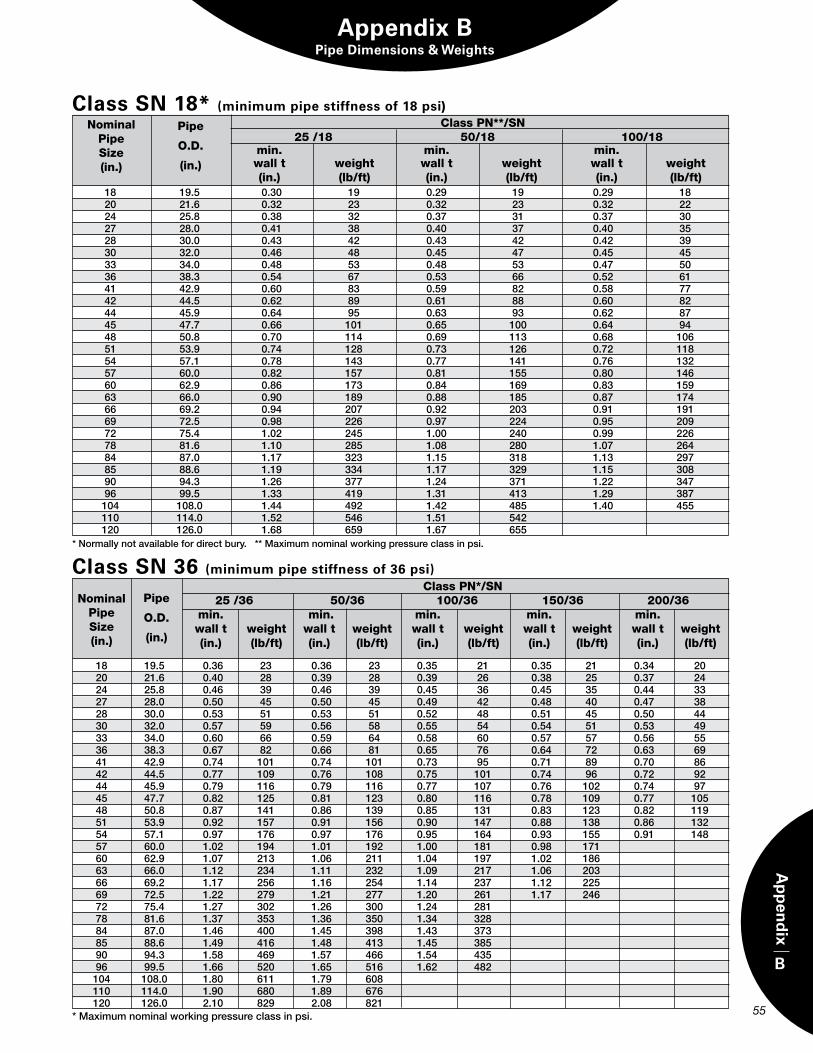
B
Ap
pen
dix
55
Appendix BPipe Dimensions & Weights
Class PN*/SN 25 /36 50/36 100/36 150/36 200/36 min. min. min. min. min. wall t weight wall t weight wall t weight wall t weight wall t weight (in.) (lb/ft) (in.) (lb/ft) (in.) (lb/ft) (in.) (lb/ft) (in.) (lb/ft)
NominalPipeSize(in.)
Pipe
O.D.
(in.)
*Maximumnominalworkingpressureclassinpsi.
Class SN 36 (minimum pipe stiffness of 36 psi)
Class SN 18* (minimum pipe stiffness of 18 psi)Class PN**/SN
25 /18 50/18 100/18 min. min. min. wall t weight wall t weight wall t weight (in.) (lb/ft) (in.) (lb/ft) (in.) (lb/ft)
Pipe
O.D.
(in.)
NominalPipeSize(in.)
*normallynotavailablefordirectbury.**Maximumnominalworkingpressureclassinpsi.
18 19.5 0.36 23 0.36 23 0.35 21 0.35 21 0.34 20 20 21.6 0.40 28 0.39 28 0.39 26 0.38 25 0.37 24 24 25.8 0.46 39 0.46 39 0.45 36 0.45 35 0.44 33 27 28.0 0.50 45 0.50 45 0.49 42 0.48 40 0.47 38 28 30.0 0.53 51 0.53 51 0.52 48 0.51 45 0.50 44 30 32.0 0.57 59 0.56 58 0.55 54 0.54 51 0.53 49 33 34.0 0.60 66 0.59 64 0.58 60 0.57 57 0.56 55 36 38.3 0.67 82 0.66 81 0.65 76 0.64 72 0.63 69 41 42.9 0.74 101 0.74 101 0.73 95 0.71 89 0.70 86 42 44.5 0.77 109 0.76 108 0.75 101 0.74 96 0.72 92 44 45.9 0.79 116 0.79 116 0.77 107 0.76 102 0.74 97 45 47.7 0.82 125 0.81 123 0.80 116 0.78 109 0.77 105 48 50.8 0.87 141 0.86 139 0.85 131 0.83 123 0.82 119 51 53.9 0.92 157 0.91 156 0.90 147 0.88 138 0.86 132 54 57.1 0.97 176 0.97 176 0.95 164 0.93 155 0.91 148 57 60.0 1.02 194 1.01 192 1.00 181 0.98 171 60 62.9 1.07 213 1.06 211 1.04 197 1.02 186 63 66.0 1.12 234 1.11 232 1.09 217 1.06 203 66 69.2 1.17 256 1.16 254 1.14 237 1.12 225 69 72.5 1.22 279 1.21 277 1.20 261 1.17 246 72 75.4 1.27 302 1.26 300 1.24 281 78 81.6 1.37 353 1.36 350 1.34 328 84 87.0 1.46 400 1.45 398 1.43 373 85 88.6 1.49 416 1.48 413 1.45 385 90 94.3 1.58 469 1.57 466 1.54 435 96 99.5 1.66 520 1.65 516 1.62 482 104 108.0 1.80 611 1.79 608 110 114.0 1.90 680 1.89 676 120 126.0 2.10 829 2.08 821
18 19.5 0.30 19 0.29 19 0.29 18 20 21.6 0.32 23 0.32 23 0.32 22 24 25.8 0.38 32 0.37 31 0.37 30 27 28.0 0.41 38 0.40 37 0.40 35 28 30.0 0.43 42 0.43 42 0.42 39 30 32.0 0.46 48 0.45 47 0.45 45 33 34.0 0.48 53 0.48 53 0.47 50 36 38.3 0.54 67 0.53 66 0.52 61 41 42.9 0.60 83 0.59 82 0.58 77 42 44.5 0.62 89 0.61 88 0.60 82 44 45.9 0.64 95 0.63 93 0.62 87 45 47.7 0.66 101 0.65 100 0.64 94 48 50.8 0.70 114 0.69 113 0.68 106 51 53.9 0.74 128 0.73 126 0.72 118 54 57.1 0.78 143 0.77 141 0.76 132 57 60.0 0.82 157 0.81 155 0.80 146 60 62.9 0.86 173 0.84 169 0.83 159 63 66.0 0.90 189 0.88 185 0.87 174 66 69.2 0.94 207 0.92 203 0.91 191 69 72.5 0.98 226 0.97 224 0.95 209 72 75.4 1.02 245 1.00 240 0.99 226 78 81.6 1.10 285 1.08 280 1.07 264 84 87.0 1.17 323 1.15 318 1.13 297 85 88.6 1.19 334 1.17 329 1.15 308 90 94.3 1.26 377 1.24 371 1.22 347 96 99.5 1.33 419 1.31 413 1.29 387 104 108.0 1.44 492 1.42 485 1.40 455 110 114.0 1.52 546 1.51 542 120 126.0 1.68 659 1.67 655
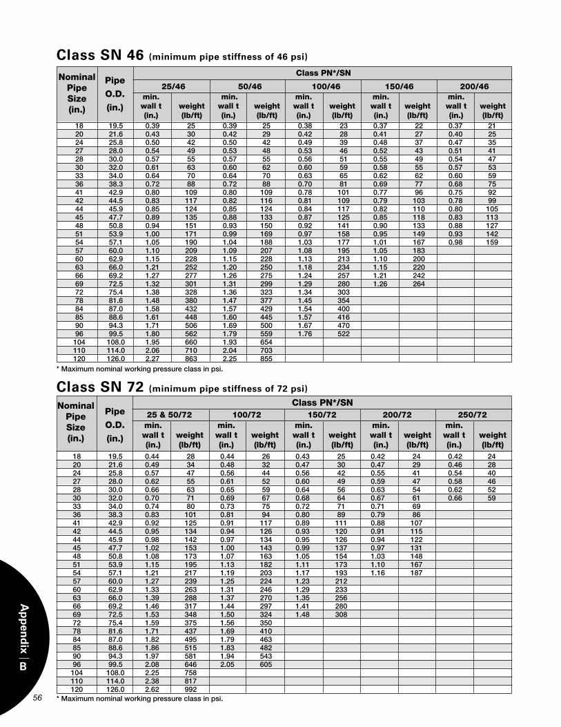
56
B
Ap
pen
dix
*Maximumnominalworkingpressureclassinpsi.
Class PN*/SN
25/46 50/46 100/46 150/46 200/46Nominal
PipeSize(in.)
Pipe
O.D.
(in.)
Class SN 46 (minimum pipe stiffness of 46 psi)
min. min. min. min. min. wall t weight wall t weight wall t weight wall t weight wall t weight (in.) (lb/ft) (in.) (lb/ft) (in.) (lb/ft) (in.) (lb/ft) (in.) (lb/ft) 18 19.5 0.39 25 0.39 25 0.38 23 0.37 22 0.37 21
20 21.6 0.43 30 0.42 29 0.42 28 0.41 27 0.40 25 24 25.8 0.50 42 0.50 42 0.49 39 0.48 37 0.47 35 27 28.0 0.54 49 0.53 48 0.53 46 0.52 43 0.51 41 28 30.0 0.57 55 0.57 55 0.56 51 0.55 49 0.54 47 30 32.0 0.61 63 0.60 62 0.60 59 0.58 55 0.57 53 33 34.0 0.64 70 0.64 70 0.63 65 0.62 62 0.60 59 36 38.3 0.72 88 0.72 88 0.70 81 0.69 77 0.68 75 41 42.9 0.80 109 0.80 109 0.78 101 0.77 96 0.75 92 42 44.5 0.83 117 0.82 116 0.81 109 0.79 103 0.78 99 44 45.9 0.85 124 0.85 124 0.84 117 0.82 110 0.80 105 45 47.7 0.89 135 0.88 133 0.87 125 0.85 118 0.83 113 48 50.8 0.94 151 0.93 150 0.92 141 0.90 133 0.88 127 51 53.9 1.00 171 0.99 169 0.97 158 0.95 149 0.93 142 54 57.1 1.05 190 1.04 188 1.03 177 1.01 167 0.98 159 57 60.0 1.10 209 1.09 207 1.08 195 1.05 183 60 62.9 1.15 228 1.15 228 1.13 213 1.10 200 63 66.0 1.21 252 1.20 250 1.18 234 1.15 220 66 69.2 1.27 277 1.26 275 1.24 257 1.21 242 69 72.5 1.32 301 1.31 299 1.29 280 1.26 264 72 75.4 1.38 328 1.36 323 1.34 303 78 81.6 1.48 380 1.47 377 1.45 354 84 87.0 1.58 432 1.57 429 1.54 400 85 88.6 1.61 448 1.60 445 1.57 416 90 94.3 1.71 506 1.69 500 1.67 470 96 99.5 1.80 562 1.79 559 1.76 522 104 108.0 1.95 660 1.93 654 110 114.0 2.06 710 2.04 703 120 126.0 2.27 863 2.25 855
min. min. min. min. min. wall t weight wall t weight wall t weight wall t weight wall t weight (in.) (lb/ft) (in.) (lb/ft) (in.) (lb/ft) (in.) (lb/ft) (in.) (lb/ft)
NominalPipeSize(in.)
Pipe
O.D.
(in.)
*Maximumnominalworkingpressureclassinpsi.
Class SN 72 (minimum pipe stiffness of 72 psi)
18 19.5 0.44 28 0.44 26 0.43 25 0.42 24 0.42 24 20 21.6 0.49 34 0.48 32 0.47 30 0.47 29 0.46 28 24 25.8 0.57 47 0.56 44 0.56 42 0.55 41 0.54 40 27 28.0 0.62 55 0.61 52 0.60 49 0.59 47 0.58 46 28 30.0 0.66 63 0.65 59 0.64 56 0.63 54 0.62 52 30 32.0 0.70 71 0.69 67 0.68 64 0.67 61 0.66 59 33 34.0 0.74 80 0.73 75 0.72 71 0.71 69 36 38.3 0.83 101 0.81 94 0.80 89 0.79 86 41 42.9 0.92 125 0.91 117 0.89 111 0.88 107 42 44.5 0.95 134 0.94 126 0.93 120 0.91 115 44 45.9 0.98 142 0.97 134 0.95 126 0.94 122 45 47.7 1.02 153 1.00 143 0.99 137 0.97 131 48 50.8 1.08 173 1.07 163 1.05 154 1.03 148 51 53.9 1.15 195 1.13 182 1.11 173 1.10 167 54 57.1 1.21 217 1.19 203 1.17 193 1.16 187 57 60.0 1.27 239 1.25 224 1.23 212 60 62.9 1.33 263 1.31 246 1.29 233 63 66.0 1.39 288 1.37 270 1.35 256 66 69.2 1.46 317 1.44 297 1.41 280 69 72.5 1.53 348 1.50 324 1.48 308 72 75.4 1.59 375 1.56 350 78 81.6 1.71 437 1.69 410 84 87.0 1.82 495 1.79 463 85 88.6 1.86 515 1.83 482 90 94.3 1.97 581 1.94 543 96 99.5 2.08 646 2.05 605 104 108.0 2.25 758 110 114.0 2.38 817 120 126.0 2.62 992
Class PN*/SN 25 & 50/72 100/72 150/72 200/72 250/72
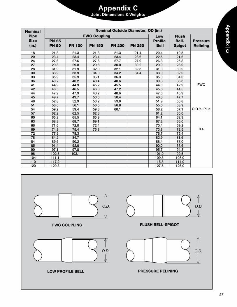
C
Ap
pen
dix
57
NominalPipeSize(in.)
FWC CouplingNominal Outside Diameter, OD (in.)
Low Flush PN 25 Profile Bell- Pressure PN 50 PN 100 PN 150 PN 200 PN 250 Bell Spigot Relining
18 21.3 21.3 21.3 21.3 21.4 20.4 19.5 20 23.4 23.4 23.4 23.4 23.6 22.5 21.6 24 27.6 27.6 27.6 27.7 27.9 26.8 25.8 27 29.8 29.8 29.8 30.0 30.2 29.0 28.0 28 31.9 31.9 32.0 32.1 32.3 31.0 30.0 30 33.9 33.9 34.0 34.2 34.4 33.0 32.0 33 35.9 35.9 36.1 36.3 35.0 34.0 36 40.2 40.2 40.4 40.6 39.3 38.3 41 44.9 44.9 45.2 45.5 44.0 42.9 42 46.5 46.5 46.8 47.2 45.6 44.5 44 47.9 47.9 48.2 48.6 47.0 45.9 45 49.7 49.7 50.0 50.4 48.8 47.7 48 52.8 52.9 53.2 53.6 51.9 50.8 51 56.0 56.1 56.5 56.8 55.0 53.9 54 59.2 59.4 59.8 60.1 58.2 57.1 57 62.2 62.5 62.8 61.2 60.0 60 65.2 65.5 65.9 64.1 62.9 63 68.3 68.7 69.1 67.2 66.0 66 71.6 72.0 72.4 70.4 69.2 69 74.9 75.4 75.8 73.8 72.5 72 77.9 78.3 76.7 75.4 78 84.2 84.7 82.9 81.6 84 89.6 90.2 88.4 87.0 85 91.4 92.0 90.0 88.6 90 97.1 97.8 95.7 94.3 96 102.5 103.1 101.0 99.5 104 111.1 109.5 108.0 110 117.2 115.5 114.0 120 129.3 127.5 126.0
FWC
o.D.’sPlus
0.4
Appendix CJoint Dimensions & Weights
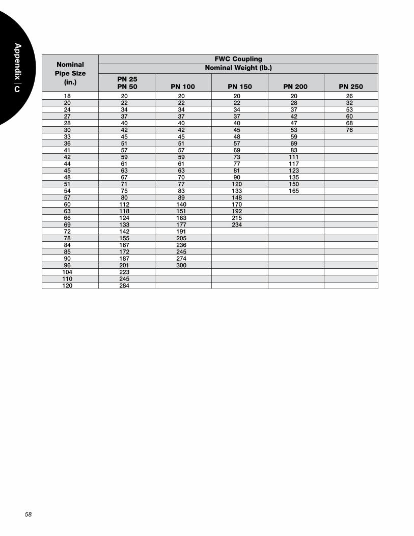
FWC CouplingNominal Weight (lb.)
PN 25 PN 50 PN 100 PN 150 PN 200 PN 250
Nominal Pipe Size
(in.)
18 20 20 20 20 26 20 22 22 22 28 32 24 34 34 34 37 53 27 37 37 37 42 60 28 40 40 40 47 68 30 42 42 45 53 76 33 45 45 48 59 36 51 51 57 69 41 57 57 69 83 42 59 59 73 111 44 61 61 77 117 45 63 63 81 123 48 67 70 90 135 51 71 77 120 150 54 75 83 133 165 57 80 89 148 60 112 140 170 63 118 151 192 66 124 163 215 69 133 177 234 72 142 191 78 155 205 84 167 236 85 172 245 90 187 274 96 201 300 104 223 110 245 120 284
58
C
Ap
pen
dix
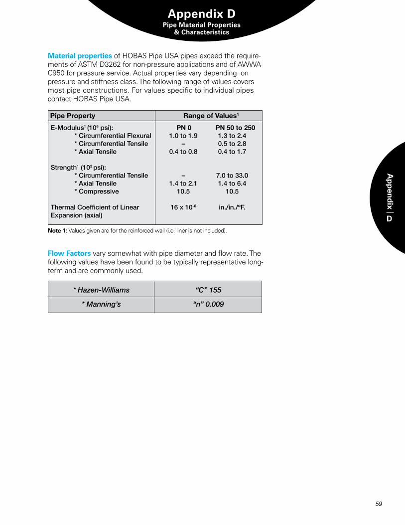
D
Ap
pen
dix
58 59
Appendix DPipe Material Properties
& Characteristics
Material properties of HOBAS Pipe USA pipes exceed the require-ments of ASTM D3262 for non-pressure applications and of AWWA C950 for pressure service. Actual properties vary depending on pressure and stiffness class. The following range of values covers most pipe constructions. For values specific to individual pipes contact HOBAS Pipe USA.
*Hazen-Williams “C”155
*Manning’s “n”0.009
Note 1: Values given are for the reinforced wall (i.e. liner is not included).
e-Modulus1(106psi): *CircumferentialFlexural *Circumferentialtensile *Axialtensilestrength1(103psi): *Circumferentialtensile *Axialtensile *Compressive
thermalCoefficientofLinearexpansion(axial)
PN 50 to 250 1.3to2.4 0.5to2.8 0.4to1.7
7.0to33.0 1.4to6.4 10.5
in./in./ºF.
PN 0 1.0to1.9 – 0.4to0.8
– 1.4to2.1 10.5
16x10-6
Pipe Property Range of Values1
Flow Factors vary somewhat with pipe diameter and flow rate. The following values have been found to be typically representative long-term and are commonly used.
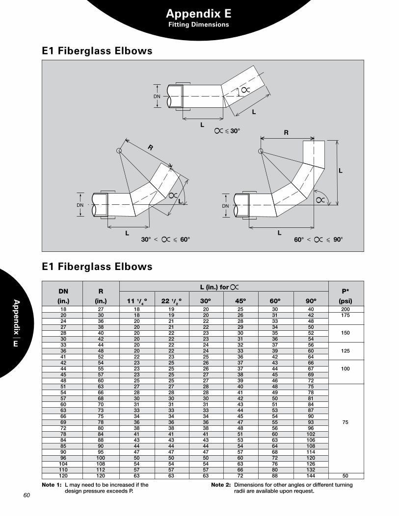
Note 1: Lmayneedtobeincreasedifthe designpressureexceedsP.
E1 Fiberglass Elbows
Note 2: Dimensionsforotheranglesordifferentturning radiiareavailableuponrequest.
E1 Fiberglass Elbows
Appendix EFitting Dimensions
60
E
Ap
pen
dix
DN R L (in.) for P*
(in.) (in.) 11 1/4º 22 1/2º 30º 45º 60º 90º (psi) 18 27 18 19 20 25 30 40 200 20 30 18 19 20 26 31 42 175 24 36 20 21 22 28 33 48 27 38 20 21 22 29 34 50 28 40 20 22 23 30 35 52 150 30 42 20 22 23 31 36 54 33 44 20 22 24 32 37 56 36 48 20 22 24 33 39 60 125 41 52 22 23 25 36 42 64 42 54 23 25 26 37 43 66 44 55 23 25 26 37 44 67 100 45 57 23 25 27 38 45 69 48 60 25 25 27 39 46 72 51 63 27 27 28 40 48 75 54 66 28 28 28 41 49 78 57 68 30 30 30 42 50 81 60 70 31 31 31 43 51 84 63 73 33 33 33 44 53 87 66 75 34 34 34 45 54 90 69 78 36 36 36 47 55 93 75 72 80 38 38 38 48 56 96 78 84 41 41 41 51 60 102 84 88 43 43 43 53 63 106 85 90 44 44 44 54 64 108 90 95 47 47 47 57 68 114 96 100 50 50 50 60 72 120 104 108 54 54 54 63 76 126 110 112 57 57 57 66 80 132 120 120 63 63 63 72 88 144 50
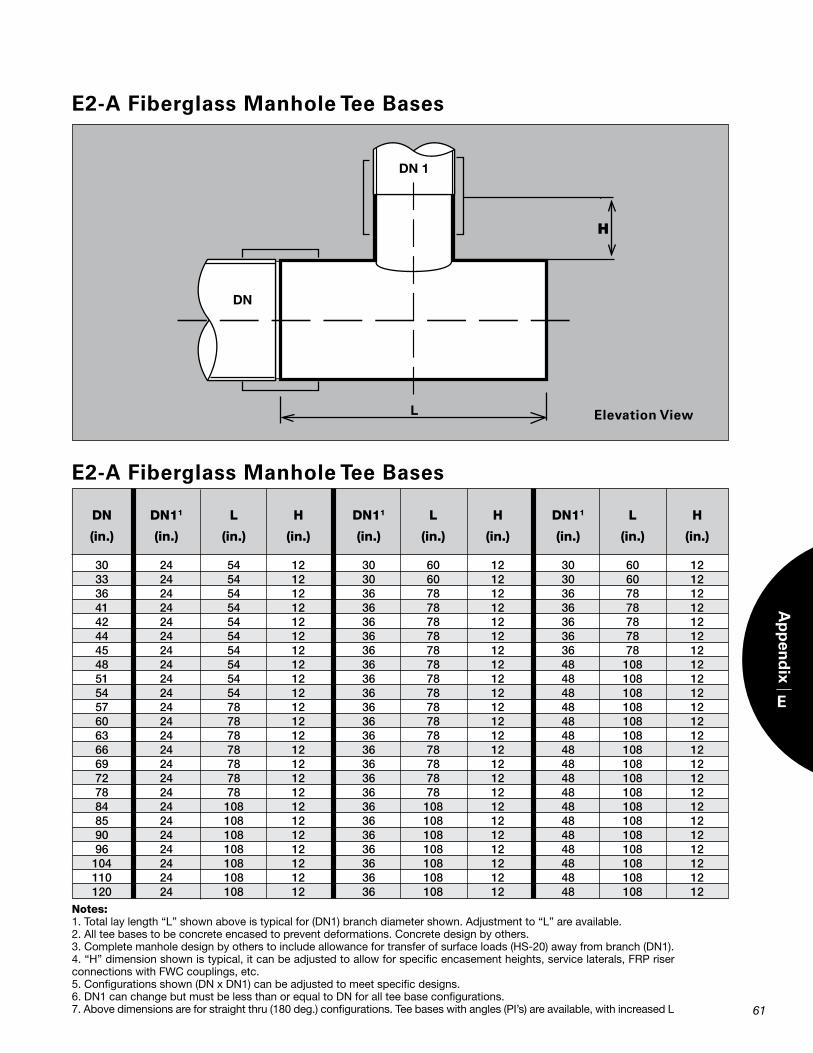
61
E2-A Fiberglass Manhole Tee Bases
E2-A Fiberglass Manhole Tee Bases
Notes: 1. Total lay length “L” shown above is typical for (DN1) branch diameter shown. Adjustment to “L” are available.2. All tee bases to be concrete encased to prevent deformations. Concrete design by others.3. Complete manhole design by others to include allowance for transfer of surface loads (HS-20) away from branch (DN1).4. “H” dimension shown is typical, it can be adjusted to allow for specific encasement heights, service laterals, FRP riser connections with FWC couplings, etc.5. Configurations shown (DN x DN1) can be adjusted to meet specific designs.6. DN1 can change but must be less than or equal to DN for all tee base configurations.7. Above dimensions are for straight thru (180 deg.) configurations. Tee bases with angles (PI’s) are available, with increased L
DN DN11 L H DN11 L H DN11 L H (in.) (in.) (in.) (in.) (in.) (in.) (in.) (in.) (in.) (in.) 30 24 54 12 30 60 12 30 60 12 33 24 54 12 30 60 12 30 60 12 36 24 54 12 36 78 12 36 78 12 41 24 54 12 36 78 12 36 78 12 42 24 54 12 36 78 12 36 78 12 44 24 54 12 36 78 12 36 78 12 45 24 54 12 36 78 12 36 78 12 48 24 54 12 36 78 12 48 108 12 51 24 54 12 36 78 12 48 108 12 54 24 54 12 36 78 12 48 108 12 57 24 78 12 36 78 12 48 108 12 60 24 78 12 36 78 12 48 108 12 63 24 78 12 36 78 12 48 108 12 66 24 78 12 36 78 12 48 108 12 69 24 78 12 36 78 12 48 108 12 72 24 78 12 36 78 12 48 108 12 78 24 78 12 36 78 12 48 108 12 84 24 108 12 36 108 12 48 108 12 85 24 108 12 36 108 12 48 108 12 90 24 108 12 36 108 12 48 108 12 96 24 108 12 36 108 12 48 108 12 104 24 108 12 36 108 12 48 108 12 110 24 108 12 36 108 12 48 108 12 120 24 108 12 36 108 12 48 108 12
E
Ap
pen
dix
H
Elevation View
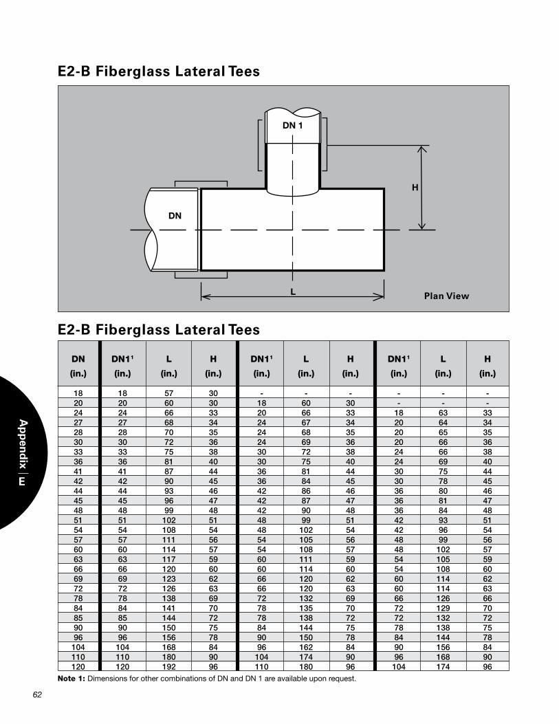
62
E
Ap
pen
dix
E2-B Fiberglass Lateral Tees
E2-B Fiberglass Lateral Tees
Note 1: Dimensions for other combinations of DN and DN 1 are available upon request.
DN DN11 L H DN11 L H DN11 L H (in.) (in.) (in.) (in.) (in.) (in.) (in.) (in.) (in.) (in.) 18 18 57 30 - - - - - - 20 20 60 30 18 60 30 - - - 24 24 66 33 20 66 33 18 63 33 27 27 68 34 24 67 34 20 64 34 28 28 70 35 24 68 35 20 65 35 30 30 72 36 24 69 36 20 66 36 33 33 75 38 30 72 38 24 66 38 36 36 81 40 30 75 40 24 69 40 41 41 87 44 36 81 44 30 75 44 42 42 90 45 36 84 45 30 78 45 44 44 93 46 42 86 46 36 80 46 45 45 96 47 42 87 47 36 81 47 48 48 99 48 42 90 48 36 84 48 51 51 102 51 48 99 51 42 93 51 54 54 108 54 48 102 54 42 96 54 57 57 111 56 54 105 56 48 99 56 60 60 114 57 54 108 57 48 102 57 63 63 117 59 60 111 59 54 105 59 66 66 120 60 60 114 60 54 108 60 69 69 123 62 66 120 62 60 114 62 72 72 126 63 66 120 63 60 114 63 78 78 138 69 72 132 69 66 126 66 84 84 141 70 78 135 70 72 129 70 85 85 144 72 78 138 72 72 132 72 90 90 150 75 84 144 75 78 138 75 96 96 156 78 90 150 78 84 144 78 104 104 168 84 96 162 84 90 156 84 110 110 180 90 104 174 90 96 168 90 120 120 192 96 110 180 96 104 174 96
Plan View
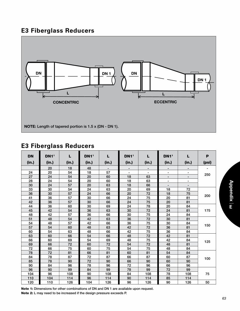
63
E
Ap
pen
dix
Note 1:DimensionsforothercombinationsofDnandDn1areavailableuponrequest.Note 2:LmayneedtobeincreasedifthedesignpressureexceedsP.
E3 Fiberglass Reducers
E3 Fiberglass Reducers
DN DN11 L DN11 L DN11 L DN11 L P (in.) (in.) (in.) (in.) (in.) (in.) (in.) (in.) (in.) (psi)
20 18 48 - - - - - - 24 20 54 18 57 - - - - 27 24 54 20 60 18 63 - -
250
28 24 54 20 60 18 63 - - 30 24 57 20 63 18 66 - - 33 30 54 24 63 20 69 18 72 36 30 57 24 66 20 72 18 75 41 36 57 30 66 24 75 20 81
200
42 36 57 30 66 24 75 20 81 44 36 60 30 69 24 78 20 84 45 42 54 36 63 30 72 24 81 175 48 42 57 36 66 30 75 24 84 51 48 54 42 63 36 72 30 81 54 48 57 42 66 36 75 30 84 57 54 60 48 63 42 72 36 81
150
60 54 63 48 66 42 75 36 84 63 60 66 54 66 48 72 42 81 66 60 69 54 69 48 75 42 84 69 66 72 60 72 54 72 48 81
125
72 66 75 60 75 54 75 48 84 78 72 81 66 81 60 81 54 84 84 78 87 72 87 66 87 60 87 85 78 90 72 90 66 90 60 90
100
90 84 96 78 96 72 96 66 96 96 90 99 84 99 78 99 72 99 104 96 108 90 108 84 108 78 108 75
110 104 114 96 114 90 114 85 114 120 110 126 104 126 96 126 90 126 50
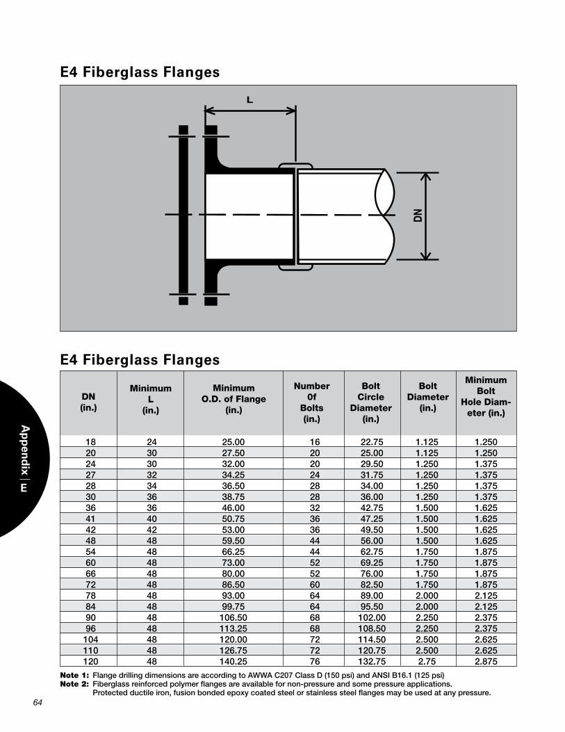
64
E
Ap
pen
dix
MinimumL
(in.)
Number Bolt Bolt 0f Circle Diameter Bolts Diameter (in.) (in.) (in.)
Minimum Bolt
Hole Diam-eter (in.)
DN(in.)
MinimumO.D. of Flange
(in.)
E4 Fiberglass Flanges
E4 Fiberglass Flanges
18 24 25.00 16 22.75 1.125 1.250 20 30 27.50 20 25.00 1.125 1.250 24 30 32.00 20 29.50 1.250 1.375 27 32 34.25 24 31.75 1.250 1.375 28 34 36.50 28 34.00 1.250 1.375 30 36 38.75 28 36.00 1.250 1.375 36 36 46.00 32 42.75 1.500 1.625 41 40 50.75 36 47.25 1.500 1.625 42 42 53.00 36 49.50 1.500 1.625 48 48 59.50 44 56.00 1.500 1.625 54 48 66.25 44 62.75 1.750 1.875 60 48 73.00 52 69.25 1.750 1.875 66 48 80.00 52 76.00 1.750 1.875 72 48 86.50 60 82.50 1.750 1.875 78 48 93.00 64 89.00 2.000 2.125 84 48 99.75 64 95.50 2.000 2.125 90 48 106.50 68 102.00 2.250 2.375 96 48 113.25 68 108.50 2.250 2.375 104 48 120.00 72 114.50 2.500 2.625 110 48 126.75 72 120.75 2.500 2.625 120 48 140.25 76 132.75 2.75 2.875Note1:FlangedrillingdimensionsareaccordingtoAWWAC207ClassD(150psi)andAnsIB16.1(125psi)Note2:Fiberglassreinforcedpolymerflangesareavailablefornon-pressureandsomepressureapplications. Protectedductileiron,fusionbondedepoxycoatedsteelorstainlesssteelflangesmaybeusedatanypressure.
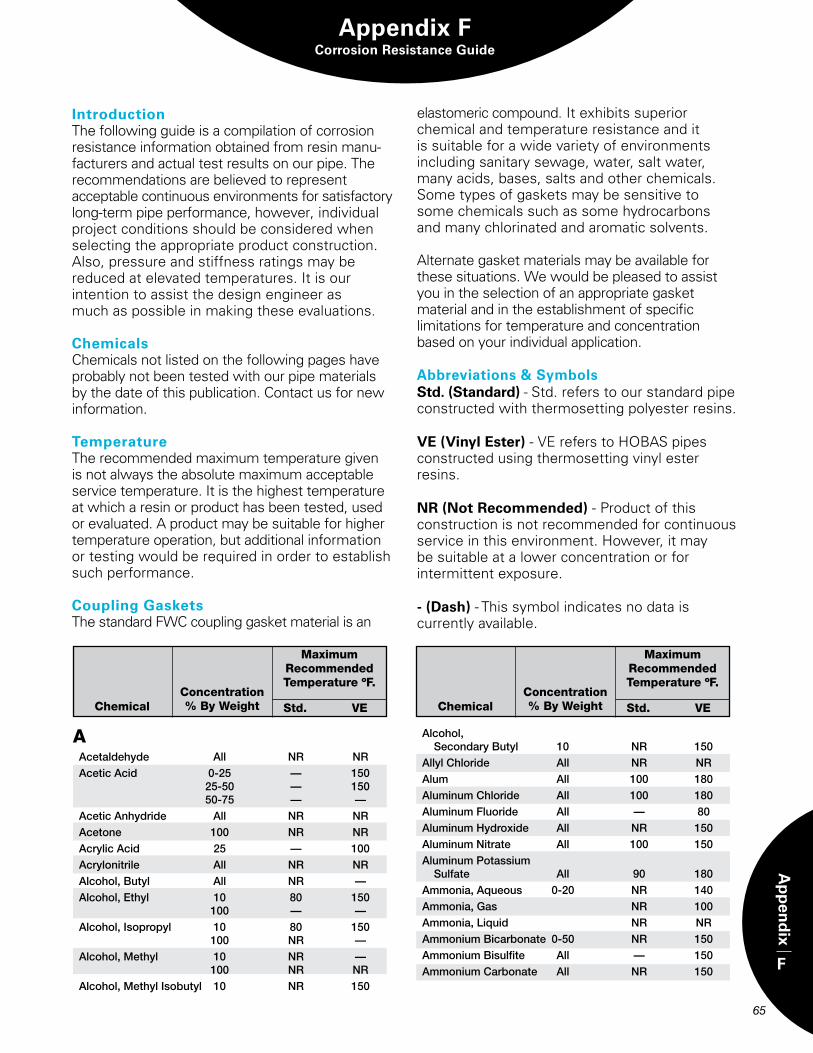
Appendix FCorrosion Resistance Guide
65
F
Ap
pen
dix
IntroductionThe following guide is a compilation of corrosion resistance information obtained from resin manu-facturers and actual test results on our pipe. The recommendations are believed to represent acceptable continuous environments for satisfactory long-term pipe performance, however, individual project conditions should be considered when selecting the appropriate product construction. Also, pressure and stiffness ratings may be reduced at elevated temperatures. It is our intention to assist the design engineer as much as possible in making these evaluations.
ChemicalsChemicals not listed on the following pages have probably not been tested with our pipe materials by the date of this publication. Contact us for new information.
TemperatureThe recommended maximum temperature given is not always the absolute maximum acceptable service temperature. It is the highest temperature at which a resin or product has been tested, used or evaluated. A product may be suitable for higher temperature operation, but additional information or testing would be required in order to establish such performance.
Coupling GasketsThe standard FWC coupling gasket material is an
elastomeric compound. It exhibits superior chemical and temperature resistance and it is suitable for a wide variety of environments including sanitary sewage, water, salt water, many acids, bases, salts and other chemicals. Some types of gaskets may be sensitive to some chemicals such as some hydrocarbons and many chlorinated and aromatic solvents.
Alternate gasket materials may be available for these situations. We would be pleased to assist you in the selection of an appropriate gasket material and in the establishment of specific limitations for temperature and concentration based on your individual application.
Abbreviations & SymbolsStd. (Standard) - Std. refers to our standard pipe constructed with thermosetting polyester resins.
VE (Vinyl Ester) - VE refers to HOBAS pipes constructed using thermosetting vinyl ester resins.
NR (Not Recommended) - Product of this construction is not recommended for continuous service in this environment. However, it may be suitable at a lower concentration or for intermittent exposure.
- (Dash) - This symbol indicates no data is currently available.
AAcetaldehyde All nr nrAceticAcid 0-25 — 150 25-50 — 150 50-75 — —AceticAnhydride All nr nrAcetone 100 nr nrAcrylicAcid 25 — 100Acrylonitrile All nr nrAlcohol,Butyl All nr —Alcohol,ethyl 10 80 150 100 — —Alcohol,Isopropyl 10 80 150 100 nr —Alcohol,Methyl 10 nr — 100 nr nrAlcohol,MethylIsobutyl 10 nr 150
Alcohol, secondaryButyl 10 nr 150AllylChloride All nr nrAlum All 100 180AluminumChloride All 100 180AluminumFluoride All — 80AluminumHydroxide All nr 150Aluminumnitrate All 100 150AluminumPotassium sulfate All 90 180Ammonia,Aqueous 0-20 nr 140Ammonia,Gas nr 100Ammonia,Liquid nr nrAmmoniumBicarbonate 0-50 nr 150AmmoniumBisulfite All — 150AmmoniumCarbonate All nr 150
ChemicalConcentration % By Weight
MaximumRecommendedTemperature ºF.
Std. VE ChemicalConcentration % By Weight
MaximumRecommendedTemperature ºF.
Std. VE
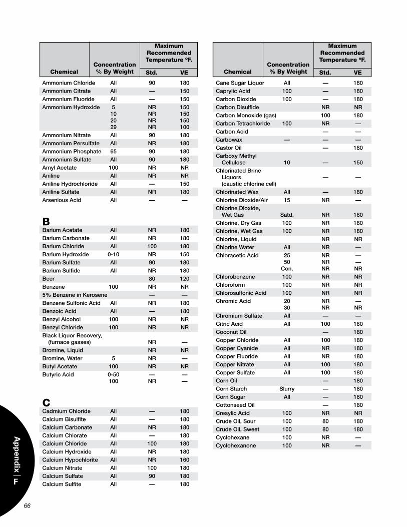
66
F
Ap
pen
dix
ChemicalConcentration % By Weight
MaximumRecommendedTemperature ºF.
Std. VE ChemicalConcentration % By Weight
MaximumRecommendedTemperature ºF.
Std. VE
AmmoniumChloride All 90 180AmmoniumCitrate All — 150AmmoniumFluoride All — 150AmmoniumHydroxide 5 nr 150 10 nr 150 20 nr 150 29 nr 100Ammoniumnitrate All 90 180AmmoniumPersulfate All nr 180AmmoniumPhosphate 65 90 180Ammoniumsulfate All 90 180AmylAcetate 100 nr nrAniline All nr nrAnilineHydrochloride All — 150Anilinesulfate All nr 180ArseniousAcid All — —
BBariumAcetate All nr 180BariumCarbonate All nr 180BariumChloride All 100 180BariumHydroxide 0-10 nr 150Bariumsulfate All 90 180Bariumsulfide All nr 180Beer 80 120Benzene 100 nr nr5%BenzeneinKerosene — —BenzenesulfonicAcid All nr 180BenzoicAcid All — 180BenzylAlcohol 100 nr nrBenzylChloride 100 nr nrBlackLiquorrecovery, (furnacegasses) nr —Bromine,Liquid nr nrBromine,Water 5 nr —ButylAcetate 100 nr nrButyricAcid 0-50 — — 100 nr —
CCadmiumChloride All — 180CalciumBisulfite All — 180CalciumCarbonate All nr 180CalciumChlorate All — 180CalciumChloride All 100 180CalciumHydroxide All nr 180CalciumHypochlorite All nr 160Calciumnitrate All 100 180Calciumsulfate All 90 180Calciumsulfite All — 180
CanesugarLiquor All — 180CaprylicAcid 100 — 180CarbonDioxide 100 — 180CarbonDisulfide nr nrCarbonMonoxide(gas) 100 180Carbontetrachloride 100 nr —CarbonAcid — —Carbowax — — —Castoroil — 180CarboxyMethyl Cellulose 10 — 150ChlorinatedBrine Liquors — — (causticchlorinecell)ChlorinatedWax All — 180ChlorineDioxide/Air 15 nr —ChlorineDioxide, WetGas satd. nr 180Chlorine,DryGas 100 nr 180Chlorine,WetGas 100 nr 180Chlorine,Liquid nr nrChlorineWater All nr —ChloraceticAcid 25 nr — 50 nr — Con. nr nrChlorobenzene 100 nr nrChloroform 100 nr nrChlorosulfonicAcid 100 nr nrChromicAcid 20 nr — 30 nr nrChromiumsulfate All — —CitricAcid All 100 180Coconutoil — 180CopperChloride All 100 180CopperCyanide All nr 180CopperFluoride All nr 180Coppernitrate All 100 180Coppersulfate All 100 180Cornoil — 180Cornstarch slurry — 180Cornsugar All — 180Cottonseedoil — 180CresylicAcid 100 nr nrCrudeoil,sour 100 80 180Crudeoil,sweet 100 80 180Cyclohexane 100 nr —Cyclohexanone 100 nr —
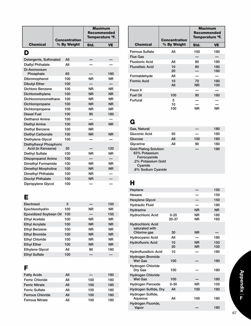
67
F
Ap
pen
dix
ChemicalConcentration % By Weight
MaximumRecommendedTemperature ºF.
Std. VE ChemicalConcentration % By Weight
MaximumRecommendedTemperature ºF.
Std. VE
DDetergents,sulfonated All — —DialfylPhthalate All — —Di-Ammonium Phosphate 65 — 180Dibromophenol 100 nr nrDibutylether 100 — —DichloroBenzene 100 nr nrDichloroethylene 100 nr nrDichloromonomethane 100 nr nrDichloropropane 100 nr nrDichloropropene 100 nr nrDieselFuel 100 90 180DiethanolAmine 100 — —DiethylAmine 100 nr nrDiethylBenzene 100 nrDiethylCarbonate 100 nr nrDiethyleneGlycol 100 — —DiethylhexylPhosphoric Acid(inKerosene) 20 — 120Diethylsulfate 100 nr nrDiisopropanolAmine 100 — —DimethylFormamide 100 nr nrDimethylMorpholine 100 nr nrDimethylPhthalate 100 nr —DioctylPhthalate 100 nr —DipropyleneGlycol 100 — —
Eelectrosol 5 — 150epichlorohydrin 100 nr nrepoxidizedsoybeanoil 100 — 150ethylAcetate 100 nr nrethylAcrylate 100 nr nrethylBenzene 100 nr nrethylBromide 100 nr nrethylChloride 100 nr nrethylether 100 nr nrethyleneGlycol All 90 180ethylsulfate 100 — —
FFattyAcids All — 180FerricChloride All 100 180Ferricnitrate All 100 180Ferricsulfate All 100 180FerrousChloride All 100 180Ferrousnitrate All 100 180
Ferroussulfate All 100 180FlueGas — —FluoboricAcid All 80 180FluosilisicAcid 10 80 180 20 — 160Formaldehyde All — —FormicAcid 10 70 180 All nr 100Freonll — —Fueloil 100 90 180Furfural 5 — — 10 — — 100 nr nr
GGas,natural — 180GluconicAcid 50 — 180Glucose All 100 180Glycerine All 90 180GoldPlatingsolution: — 180 63%Potassium Ferrocyanide .2%PotassiumGold Cyanide .8%sodiumCyanide
HHeptane — 150Hexane — 150HexyleneGlycol — 150HydraulicFluid — 180Hydrazine nr nrHydrochloricAcid 0-20 nr 180 20-37 nr 160HydrochloricAcid saturatedwith Chlorinegas 30 nr —HydrocyanicAcid All — 180HydrofluoricAcid 10 nr 150 20 nr 100HydrofluosilicicAcid 10 — 180HydrogenBromide WetGas 100 — 180HydrogenChloride DryGas 100 — 180HydrogenChloride WetGas 100 — 180HydrogenPeroxide 0-30 nr 150Hydrogensulfide,Dry All 100 180Hydrogensulfide, Aqueous All 100 180HydrogenFluoride, Vapor — 180
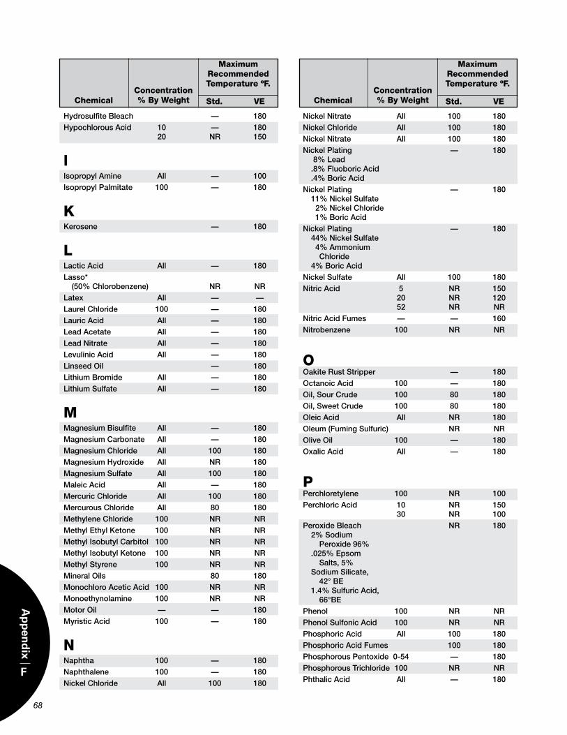
68
F
Ap
pen
dix
HydrosulfiteBleach — 180HypochlorousAcid 10 — 180 20 nr 150
lIsopropylAmine All — 100IsopropylPalmitate 100 — 180
KKerosene — 180
LLacticAcid All — 180Lasso* (50%Chlorobenzene) nr nrLatex All — —LaurelChloride 100 — 180LauricAcid All — 180LeadAcetate All — 180Leadnitrate All — 180LevulinicAcid All — 180Linseedoil — 180LithiumBromide All — 180Lithiumsulfate All — 180
MMagnesiumBisulfite All — 180MagnesiumCarbonate All — 180MagnesiumChloride All 100 180MagnesiumHydroxide All nr 180Magnesiumsulfate All 100 180MaleicAcid All — 180MercuricChloride All 100 180MercurousChloride All 80 180MethyleneChloride 100 nr nrMethylethylKetone 100 nr nrMethylIsobutylCarbitol 100 nr nrMethylIsobutylKetone 100 nr nrMethylstyrene 100 nr nrMineraloils 80 180MonochloroAceticAcid 100 nr nrMonoethynolamine 100 nr nrMotoroil — — 180MyristicAcid 100 — 180
Nnaphtha 100 — 180naphthalene 100 — 180nickelChloride All 100 180
nickelnitrate All 100 180nickelChloride All 100 180nickelnitrate All 100 180nickelPlating — 180 8%Lead .8%FluoboricAcid .4%BoricAcidnickelPlating — 180 11%nickelsulfate 2%nickelChloride 1%BoricAcidnickelPlating — 180 44%nickelsulfate 4%Ammonium Chloride 4%BoricAcidnickelsulfate All 100 180nitricAcid 5 nr 150 20 nr 120 52 nr nrnitricAcidFumes — — 160nitrobenzene 100 nr nr
Ooakiteruststripper — 180octanoicAcid 100 — 180oil,sourCrude 100 80 180oil,sweetCrude 100 80 180oleicAcid All nr 180oleum(Fumingsulfuric) nr nroliveoil 100 — 180oxalicAcid All — 180
PPerchloretylene 100 nr 100PerchloricAcid 10 nr 150 30 nr 100PeroxideBleach nr 180 2%sodium Peroxide96% .025%epsom salts,5% sodiumsilicate, 42°Be 1.4%sulfuricAcid, 66°BePhenol 100 nr nrPhenolsulfonicAcid 100 nr nrPhosphoricAcid All 100 180PhosphoricAcidFumes 100 180PhosphorousPentoxide 0-54 — 180Phosphoroustrichloride 100 nr nrPhthalicAcid All — 180
ChemicalConcentration % By Weight
MaximumRecommendedTemperature ºF.
Std. VE ChemicalConcentration % By Weight
MaximumRecommendedTemperature ºF.
Std. VE
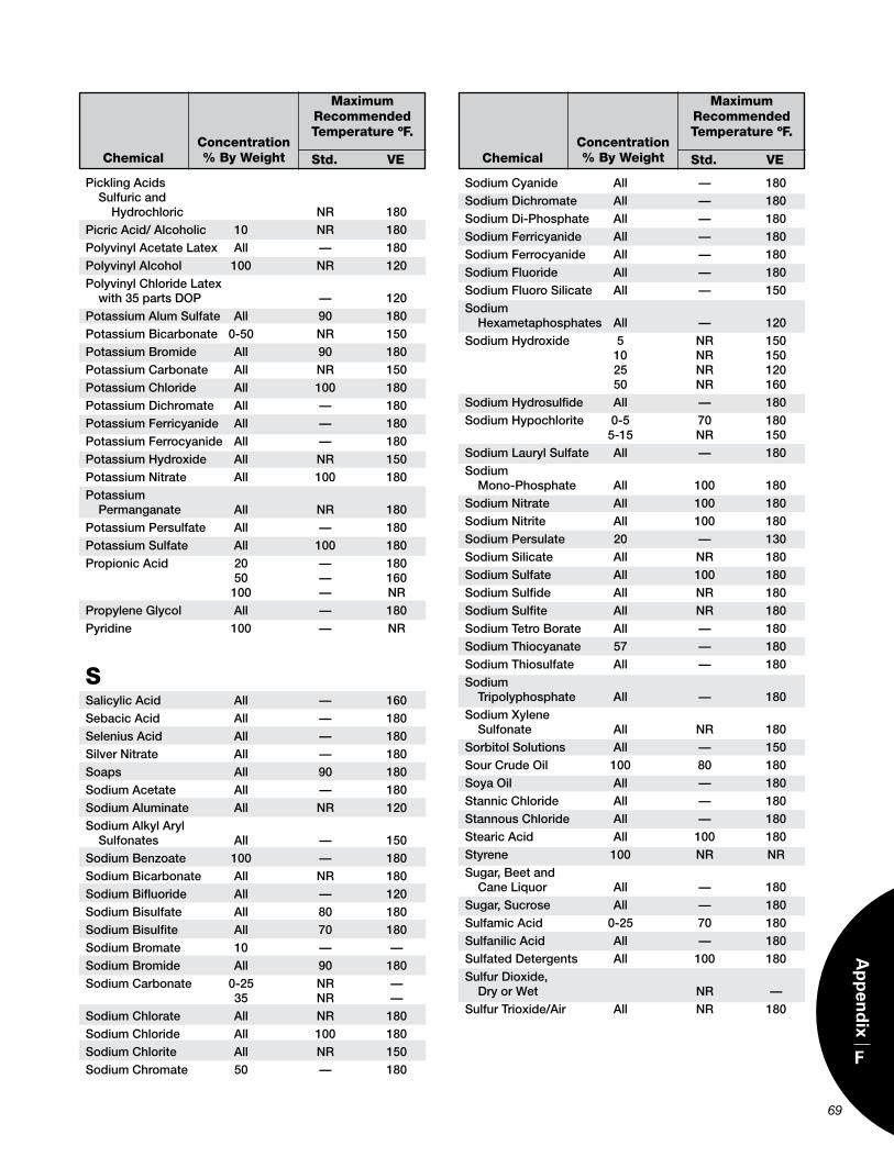
69
F
Ap
pen
dix
PicklingAcids sulfuricand Hydrochloric nr 180PicricAcid/Alcoholic 10 nr 180PolyvinylAcetateLatex All — 180PolyvinylAlcohol 100 nr 120PolyvinylChlorideLatex with35partsDoP — 120PotassiumAlumsulfate All 90 180PotassiumBicarbonate 0-50 nr 150PotassiumBromide All 90 180PotassiumCarbonate All nr 150PotassiumChloride All 100 180PotassiumDichromate All — 180PotassiumFerricyanide All — 180PotassiumFerrocyanide All — 180PotassiumHydroxide All nr 150Potassiumnitrate All 100 180Potassium Permanganate All nr 180PotassiumPersulfate All — 180Potassiumsulfate All 100 180PropionicAcid 20 — 180 50 — 160 100 — nrPropyleneGlycol All — 180Pyridine 100 — nr
SsalicylicAcid All — 160sebacicAcid All — 180seleniusAcid All — 180silvernitrate All — 180soaps All 90 180sodiumAcetate All — 180sodiumAluminate All nr 120sodiumAlkylAryl sulfonates All — 150sodiumBenzoate 100 — 180sodiumBicarbonate All nr 180sodiumBifluoride All — 120sodiumBisulfate All 80 180sodiumBisulfite All 70 180sodiumBromate 10 — —sodiumBromide All 90 180sodiumCarbonate 0-25 nr — 35 nr —sodiumChlorate All nr 180sodiumChloride All 100 180sodiumChlorite All nr 150sodiumChromate 50 — 180
sodiumCyanide All — 180sodiumDichromate All — 180sodiumDi-Phosphate All — 180sodiumFerricyanide All — 180sodiumFerrocyanide All — 180sodiumFluoride All — 180sodiumFluorosilicate All — 150sodium Hexametaphosphates All — 120sodiumHydroxide 5 nr 150 10 nr 150 25 nr 120 50 nr 160sodiumHydrosulfide All — 180sodiumHypochlorite 0-5 70 180 5-15 nr 150sodiumLaurylsulfate All — 180sodium Mono-Phosphate All 100 180sodiumnitrate All 100 180sodiumnitrite All 100 180sodiumPersulate 20 — 130sodiumsilicate All nr 180sodiumsulfate All 100 180sodiumsulfide All nr 180sodiumsulfite All nr 180sodiumtetroBorate All — 180sodiumthiocyanate 57 — 180sodiumthiosulfate All — 180sodium tripolyphosphate All — 180sodiumXylene sulfonate All nr 180sorbitolsolutions All — 150sourCrudeoil 100 80 180soyaoil All — 180stannicChloride All — 180stannousChloride All — 180stearicAcid All 100 180styrene 100 nr nrsugar,Beetand CaneLiquor All — 180sugar,sucrose All — 180sulfamicAcid 0-25 70 180sulfanilicAcid All — 180sulfatedDetergents All 100 180sulfurDioxide, DryorWet nr —sulfurtrioxide/Air All nr 180
ChemicalConcentration % By Weight
MaximumRecommendedTemperature ºF.
Std. VE ChemicalConcentration % By Weight
MaximumRecommendedTemperature ºF.
Std. VE
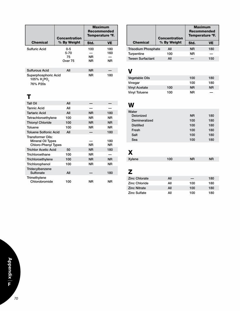
70
F
Ap
pen
dix
sulfuricAcid 0-5 100 180 5-70 — 160 75 nr — over75 nr nr
sulfurousAcid All nr —superphosphoricAcid nr 180 105%H3Po3
76%P20s
Ttalloil All — —tannicAcid All — —tartaricAcid All nr 180tetrachloroethylene 100 nr nrthionylChloride 100 nr nrtoluene 100 nr nrtoluenesolfonicAcid All — 180transformeroils: Mineraloiltypes — 180 Chloro-Phenyltypes nr nrtrichlorAceticAcid 50 nr 180trichloroethane 100 nr —trichloroethylene 100 nr nrtrichlorophenol 100 nr nrtridecylbenzene sulfonate All — 180trimethylene Chlorobromide 100 nr nr
trisodiumPhosphate All nr 180turpentine 100 nr —tweensurfactant All — 150
VVegetableoils 100 180Vinegar 100 180VinylAcetate 100 nr nrVinyltoluene 100 nr —
WWater Deionized nr 180 Demineralized 100 180 Distilled 100 180 Fresh 100 180 salt 100 180 sea 100 180
XXylene 100 nr nr
ZZincChlorate All — 180ZincChloride All 100 180Zincnitrate All 100 180Zincsulfate All 100 180
ChemicalConcentration % By Weight
MaximumRecommendedTemperature ºF.
Std. VE ChemicalConcentration % By Weight
MaximumRecommendedTemperature ºF.
Std. VE
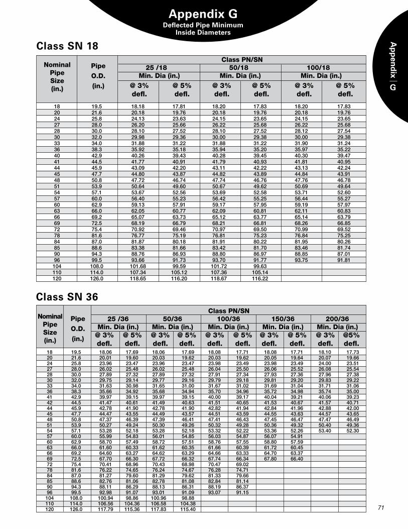
G
Ap
pen
dix
Appendix GDeflected Pipe Minimum
Inside Diameters
Class PN/SN 25 /18 50/18 100/18 Min. Dia (in.) Min. Dia (in.) Min. Dia (in.)
Pipe
O.D.
(in.)
NominalPipeSize(in.) @ 3% @ 5% @ 3% @ 5% @ 3% @ 5%
defl. defl. defl. defl. defl. defl.
18 19.5 18.18 17.81 18.20 17.83 18.20 17.83 20 21.6 20.18 19.76 20.18 19.76 20.18 19.76 24 25.8 24.13 23.63 24.15 23.65 24.15 23.65 27 28.0 26.20 25.66 26.22 25.68 26.22 25.68 28 30.0 28.10 27.52 28.10 27.52 28.12 27.54 30 32.0 29.98 29.36 30.00 29.38 30.00 29.38 33 34.0 31.88 31.22 31.88 31.22 31.90 31.24 36 38.3 35.92 35.18 35.94 35.20 35.97 35.22 40 42.9 40.26 39.43 40.28 39.45 40.30 39.47 41 44.5 41.77 40.91 41.79 40.93 41.81 40.95 44 45.9 43.09 42.20 43.11 42.22 43.13 42.24 45 47.7 44.80 43.87 44.82 43.89 44.84 43.91 48 50.8 47.72 46.74 47.74 46.76 47.76 46.78 51 53.9 50.64 49.60 50.67 49.62 50.69 49.64 54 57.1 53.67 52.56 53.69 52.58 53.71 52.60 57 60.0 56.40 55.23 56.42 55.25 56.44 55.27 60 62.9 59.13 57.91 59.17 57.95 59.19 57.97 63 66.0 62.05 60.77 62.09 60.81 62.11 60.83 66 69.2 65.07 63.73 65.12 63.77 65.14 63.79 69 72.5 68.19 66.79 68.21 66.81 68.26 66.85 72 75.4 70.92 69.46 70.97 69.50 70.99 69.52 78 81.6 76.77 75.19 76.81 75.23 76.84 75.25 84 87.0 81.87 80.18 81.91 80.22 81.95 80.26 85 88.6 83.38 81.66 83.42 81.70 83.46 81.74 90 94.3 88.76 86.93 88.80 86.97 88.85 87.01 96 99.5 93.66 91.73 93.70 91.77 93.75 91.81 104 108.0 101.68 99.59 101.72 99.63 110 114.0 107.34 105.12 107.36 105.14 120 126.0 118.65 116.20 118.67 116.22
Class SN 18
Class PN/SN 25 /36 50/36 100/36 150/36 200/36 Min. Dia (in.) Min. Dia (in.) Min. Dia (in.) Min. Dia (in.) Min. Dia (in.)
NominalPipeSize(in.)
Pipe
O.D.
(in.) @ 3% @ 5% @ 3% @ 5% @ 3% @ 5% @ 3% @ 5% @ 3% @5% defl. defl. defl. defl. defl. defl. defl. defl. defl. defl.
Class SN 36
71
18 19.5 18.06 17.69 18.06 17.69 18.08 17.71 18.08 17.71 18.10 17.73 20 21.6 20.01 19.60 20.03 19.62 20.03 19.62 20.05 19.64 20.07 19.66 24 25.8 23.96 23.47 23.96 23.47 23.98 23.49 23.98 23.49 24.00 23.51 27 28.0 26.02 25.48 26.02 25.48 26.04 25.50 26.06 25.52 26.08 25.54 28 30.0 27.89 27.32 27.89 27.32 27.91 27.34 27.93 27.36 27.96 27.38 30 32.0 29.75 29.14 29.77 29.16 29.79 29.18 29.81 29.20 29.83 29.22 33 34.0 31.63 30.98 31.65 31.00 31.67 31.02 31.69 31.04 31.71 31.06 36 38.3 35.66 34.92 35.68 34.94 35.70 34.96 35.72 34.98 35.74 35.00 41 42.9 39.97 39.15 39.97 39.15 40.00 39.17 40.04 39.21 40.06 39.23 42 44.5 41.47 40.61 41.49 40.63 41.51 40.65 41.53 40.67 41.57 40.71 44 45.9 42.78 41.90 42.78 41.90 42.82 41.94 42.84 41.96 42.88 42.00 45 47.7 44.47 43.55 44.49 43.57 44.51 43.59 44.55 43.63 44.57 43.65 48 50.8 47.37 46.39 47.39 46.41 47.41 46.43 47.45 46.47 47.47 46.49 51 53.9 50.27 49.24 50.30 49.26 50.32 49.28 50.36 49.32 50.40 49.36 54 57.1 53.28 52.18 53.28 52.18 53.32 52.22 53.36 52.26 53.40 52.30 57 60.0 55.99 54.83 56.01 54.85 56.03 54.87 56.07 54.91 60 62.9 58.70 57.49 58.72 57.51 58.76 57.55 58.80 57.59 63 66.0 61.60 60.33 61.62 60.35 61.66 60.39 61.72 60.45 66 69.2 64.60 63.27 64.62 63.29 64.66 63.33 64.70 63.37 69 72.5 67.70 66.30 67.72 66.32 67.74 66.34 67.80 66.40 72 75.4 70.41 68.96 70.43 68.98 70.47 69.02 78 81.6 76.22 74.65 76.24 74.67 76.28 74.71 84 87.0 81.27 79.60 81.29 79.62 81.33 79.66 85 88.6 82.76 81.06 82.78 81.08 82.84 81.14 90 94.3 88.11 86.29 88.13 86.31 88.19 86.37 96 99.5 92.98 91.07 93.01 91.09 93.07 91.15 104 108.0 100.94 98.86 100.96 98.88 110 114.0 106.56 104.36 106.58 104.38 120 126.0 117.79 115.36 117.83 115.40
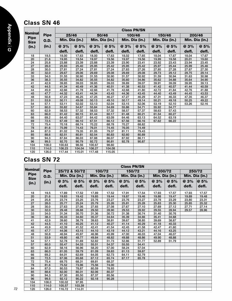
72
G
Ap
pen
dix
Class PN/SN 25/46 50/46 100/46 150/46 200/46 Min. Dia (in.) Min. Dia (in.) Min. Dia (in.) Min. Dia (in.) Min. Dia (in.)
NominalPipeSize(in.)
Pipe
O.D.
(in.) @ 3% @ 5% @ 3% @ 5% @ 3% @ 5% @ 3% @ 5% @ 3% @ 5% defl. defl. defl. defl. defl. defl. defl. defl. defl. defl.
18 19.5 18.00 17.63 18.00 17.63 18.02 17.65 18.04 17.67 18.04 17.67 20 21.6 19.95 19.54 19.97 19.56 19.97 19.56 19.99 19.58 20.01 19.60 24 25.8 23.88 23.39 23.88 23.39 23.90 23.41 23.92 23.43 23.94 23.45 27 28.0 25.93 25.40 25.95 25.42 25.95 25.42 25.97 25.44 25.99 25.46 28 30.0 27.81 27.24 27.81 27.24 27.83 27.26 27.85 27.28 27.87 27.30 30 32.0 29.67 29.06 29.69 29.08 29.69 29.08 29.73 29.12 29.75 29.14 33 34.0 31.55 30.90 31.55 30.90 31.57 30.92 31.59 30.94 31.63 30.98 36 38.3 35.55 34.82 35.55 34.82 35.60 34.86 35.62 34.88 35.64 34.90 41 42.9 39.85 39.03 39.85 39.03 39.89 39.07 39.91 39.09 39.95 39.13 42 44.5 41.34 40.49 41.36 40.51 41.38 40.53 41.42 40.57 41.44 40.59 44 45.9 42.66 41.78 42.66 41.78 42.68 41.80 42.72 41.84 42.76 41.88 45 47.7 44.32 43.41 44.34 43.43 44.36 43.45 44.40 43.49 44.45 43.53 48 50.8 47.23 46.25 47.25 46.27 47.27 46.29 47.31 46.33 47.35 46.37 51 53.9 50.11 49.08 50.13 49.10 50.17 49.14 50.21 49.18 50.25 49.22 54 57.1 53.11 52.02 53.13 52.04 53.15 52.06 53.19 52.10 53.26 52.16 57 60.0 55.82 54.67 55.84 54.69 55.86 54.71 55.92 54.77 60 62.9 58.53 57.32 58.53 57.32 58.57 57.37 58.63 57.43 63 66.0 61.42 60.15 61.44 60.17 61.48 60.21 61.54 60.27 66 69.2 64.40 63.07 64.42 63.09 64.46 63.13 64.52 63.19 69 72.5 67.49 66.10 67.51 66.12 67.56 66.16 67.62 66.22 72 75.4 70.18 68.74 70.22 68.78 70.27 68.82 78 81.6 75.99 74.43 76.01 74.45 76.05 74.49 84 87.0 81.02 79.35 81.05 79.37 81.11 79.43 85 88.6 82.51 80.81 82.54 80.83 82.60 80.89 90 94.3 87.84 86.03 87.88 86.07 87.92 86.11 96 99.5 92.70 90.79 92.72 90.81 92.78 90.87 104 108.0 100.63 98.56 100.67 98.60 110 114.0 106.23 104.04 106.27 104.08 120 126.0 117.44 115.01 117.48 115.05
Class SN 46
Class PN/SN 25/72 & 50/72 100/72 150/72 200/72 250/72 Min. Dia (in.) Min. Dia (in.) Min. Dia (in.) Min. Dia (in.) Min. Dia (in.)
NominalPipeSize(in.)
Pipe
O.D.
(in.) @ 3% @ 5% @ 3% @ 5% @ 3% @ 5% @ 3% @ 5% @ 3% @ 5% defl. defl. defl. defl. defl. defl. defl. defl. defl. defl.
18 19.5 17.89 17.52 17.89 17.52 17.91 17.54 17.93 17.57 17.93 17.57 20 21.6 19.83 19.42 19.85 19.44 19.87 19.46 19.88 19.47 19.89 19.48 24 25.8 23.74 23.25 23.76 23.27 23.76 23.27 23.78 23.29 23.80 23.31 27 28.0 25.77 25.24 25.79 25.26 25.81 25.28 25.83 25.30 25.85 25.32 28 30.0 27.63 27.06 27.65 27.08 27.67 27.10 27.69 27.12 27.71 27.14 30 32.0 29.48 28.88 29.50 28.90 29.53 28.92 29.55 28.94 29.57 28.96 33 34.0 31.34 30.70 31.36 30.72 31.38 30.74 31.40 30.76 36 38.3 35.33 34.60 35.37 34.64 35.39 34.66 35.41 34.68 41 42.9 39.60 38.79 39.63 38.81 39.67 38.85 39.69 38.87 42 44.5 41.10 40.25 41.12 40.27 41.14 40.29 41.18 40.33 44 45.9 42.39 41.52 42.41 41.54 42.45 41.58 42.47 41.60 45 47.7 44.06 43.15 44.10 43.19 44.12 43.21 44.16 43.25 48 50.8 46.94 45.97 46.96 45.99 47.00 46.03 47.04 46.07 51 53.9 49.80 48.77 49.84 48.82 49.88 48.86 49.90 48.88 54 57.1 52.78 51.69 52.82 51.73 52.86 51.77 52.89 51.79 57 60.0 55.47 54.33 55.51 54.37 55.55 54.41 60 62.9 58.16 56.96 58.20 57.00 58.24 57.04 63 66.0 61.05 59.79 61.09 59.83 61.13 59.87 66 69.2 64.01 62.69 64.05 62.73 64.11 62.79 69 72.5 67.06 65.68 67.12 65.74 67.17 65.78 72 75.4 69.75 68.31 69.81 68.37 78 81.6 75.52 73.96 75.56 74.00 84 87.0 80.53 78.87 80.59 78.93 85 88.6 82.00 80.31 82.06 80.37 90 94.3 87.30 85.50 87.37 85.56 96 99.5 92.12 90.22 92.18 90.28 104 108.0 100.02 97.95 110 114.0 105.57 103.39 120 126.0 116.72 114.31
Class SN 72

R12 11/2010


![Composites] Fiberglass Reinforced Plastics](https://static.documents.pub/doc/80x56/54357942219acdd95f8b47ae/composites-fiberglass-reinforced-plastics.jpg)


