191 The use of diamond-impreTmted tools for rock-slicing, t By K. C. DURHAM, D.Se., Ph.D., S.D. Chief Petrographer, Geological Survey and Museum, London and J. T. TAYLOR Chief Instructor, Government Training Centre, Letchworth. [Read March 23, 1950.] Introduction. ~ OR the cutting of chips from rocks preparatory to thin-slicing, it has been standard practice for many years to use notched soft iron disks, manually armed with diamond powder. The latest machines employing cutting-disks of this type at the Geological Museum were built at the Government Training Centre, Ascot Works, Letchworth, to the design of the late Dr. H. H. Thomas and of Mr. W. Ward of the Centre. These are powered with 0.25 horse-power variable speed direct current motors, giving a maximum disk speed of 280 revolutions perminute. By means of rheostats, control of speed as sensitive as that obtainable with a treadle type of machine (see A. V. Weatherhead 2) is achieved. The normal speed for cutting is 160 to 180 r.p.m. In cutting a hard rock such as chert, it may be necessary to recharge the disk with diamond several times during the operation. The rock-specimen is held in a steel clamp with hardwood liners, mounted on a swinging arm. The rock is held in contact with the disk by the tension of a spring, or, during delicate work, by the pressure of the hand. Water is employed as a lubricant for cutting, except for water-soluble minerals; whe.n paraffin is employed. A slice- holder, designed by Mr. D. W. Hepple, which fits into the clamp, enables chips already mounted on glass slips to be sawn to a minimum thickness of about 0.3 ram. These machines have given excellent service and have been widely copied. By means of three such machines at the Museum, and one at the Edinburgh office of the Geological Survey, a total of 14,600 thin Sections were made during the years 1935 to 1946. Coarse grinding during this period was carried out by means of cast iron laps using silicon carbide as an abrasive. i Published by permission of the Director of the G(~logical Survey and Museum, and the Manager of the Government Training Centre, Letchworth. '~ A. V. Weatherhead, Petrographic micro-technique. London, 1947. "[M.A. 10- 1~.]
Transcript
191
The use of diamond-impreTmted tools for rock-slicing, t
By K. C. DURHAM, D.Se., Ph.D., S.D.
Chief Petrographer, Geological Survey and Museum, London
and J. T. TAYLOR
Chief Instructor, Government Training Centre, Letchworth.
[Read March 23, 1950.]
Introduction.
~ OR the cutting of chips from rocks preparatory to thin-slicing, it has been standard practice for many years to use notched soft iron disks,
manually armed with diamond powder. The latest machines employing cutting-disks of this type at the Geological Museum were built at the Government Training Centre, Ascot Works, Letchworth, to the design of the late Dr. H. H. Thomas and of Mr. W. Ward of the Centre. These are powered with 0.25 horse-power variable speed direct current motors, giving a maximum disk speed of 280 revolutions perminute. By means of rheostats, control of speed as sensitive as that obtainable with a treadle type of machine (see A. V. Weatherhead 2) is achieved. The normal speed for cutting is 160 to 180 r.p.m. In cutting a hard rock such as chert, it may be necessary to recharge the disk with diamond several times during the operation. The rock-specimen is held in a steel clamp with hardwood liners, mounted on a swinging arm. The rock is held in contact with the disk by the tension of a spring, or, during delicate work, by the pressure of the hand. Water is employed as a lubricant for cutting, except for water-soluble minerals; whe.n paraffin is employed. A slice- holder, designed by Mr. D. W. Hepple, which fits into the clamp, enables chips already mounted on glass slips to be sawn to a minimum thickness of about 0.3 ram. These machines have given excellent service and have been widely copied. By means of three such machines at the Museum, and one at the Edinburgh office of the Geological Survey, a total of 14,600 thin Sections were made during the years 1935 to 1946. Coarse grinding during this period was carried out by means of cast iron laps using silicon carbide as an abrasive.
i Published by permission of the Director of the G(~logical Survey and Museum, and the Manager of the Government Training Centre, Letchworth.
'~ A. V. Weatherhead, Petrographic micro-technique. London, 1947. "[M.A. 10- 1~.]
192 K. C. D U N H A M A N D J . T. TAYLOR ON
The development of diamond-impregnated grinding-laps was made necessary by the general introduction into machine-tool practice of tools tipped with tungsten , tantalum, and titanium carbides. Owing to its combustibility, diamond cannot be bonded with fused metal, or with vitreous bonds fired at normal kiln temperatures. The first diamond- impregnated laps to prove successful employed resinoid bonds. An application of this type of lap to rock-sectioning has been described, 1 but the rate of wear appears, from the figures quoted, to be excessive. The problem of bonding diamonds with metal was solved, shortly before the recent war, by an application of the process of powder metallurgy. In this, the diamond powder is mixed with powdered metal and sintered without fusion of the metal. 2 Complete laps or disks, or merely cutting surfaces may be formed in this way. Recognizing the importance to the war-effort of tools of this type, the Belgian pioneer Mr. Peter Neven was invited to this country by the Ministry of Supply in 1940, and a range of Ms products came on to the market in 1941-2. Probably the earliest application of metal-bonded diamond-impregnated tools to mineral subjects was to the cutting of oriented quartz oscillator plates, s
Experiments in the application of diamond-impregnated cut-off disks to rock-slicing were commenced by Dr. J. Phemister and- Dr. A. G. MacGregor in 1945. The Letchworth machine at the Edinburgh office was equipped with a 6-inch diamond-impregnated cutting-disk, and the cutting speed was raised to 500 r.p.m. A' positive feed was found to be necesss, ry, and a screw control to the swinging arm, designed by Mr. J. McCall, was added to the machine. The disk here has given satisfactory service, but now shows signs of wear. In London, the construction of a new and heavier machine, capable of giving higher speeds was put in hand ; details of this machine are given below.
Meanwhile in the laboratory of the Treforest sparking-plug factory operated by the K.L.G. Company for the Ministry of Supply, Mr. T. G. Jones had constructed a machine incorporating a 6-inch diamond- impregnated cut-off disk of Van Moppes manufacture, and a diamond-
1 A. E. Alexander, Use of diamond laps in making petrographic and metallo- graphic sections. Industrial Diamond Rev., 1942, vol. 2, p. 27. Anonymous, The production of quartz crystals. Ibid., 1944, vol. 4, pp. 56-58. P. Grodzinski, Diamond and gemstone industrial production methods--V. Ibid., 1948, vol. 8, pp. 279-284. [M.A. 10-559.]
2 H. E. Hall in J. Wulff (editor), Powder metallurgy. Amer. Soc. Metals, Cleve- land, Ohio, 1942.
s E. T. Larson, Now it can be told. Industrial Diamond Rev., 1946, vol. 6, pp. 261-262.
D I A M O N D - I M P R E G N A T E D TOOLS FOR ROCK-SLICING 193
impregnated grlnding-lap, for sectioning sparking-plug insulators (com- posed of 'corundite', eorur~dum plus lime-magnesia glass). This was in constant service for five years before the factory was closed in 1946, when the machine was purchased for the Geological Survey. It continues to give excellent service after eight years of daily mineral cutting, and the disk shows as yet no signs of wear.
The cutting portion of the Treforest machine consists of a horizontal spindle carrying the cutting-disk and a pulley, driven at 2400 r.p.m, by a flat belt from a 440-volt alternating current 0-25 horse-power motor. A lathe-type feed, mounting a hardwood-lined clamp, gives screw- controlled motion towards and across the periphery of the disk. To prevent rusting, the coolant used is water mixed with soda and soluble oil. A motorized suds pump, submerge d in a tank beneath the machine, supplies the coolant to the cutting surface and to the grinding laps, and the liquid returns to the tank after use. The maximum length of cut obtainabl~ with this machine is 1 inch.
Rock-cutting machine.
For proper efficiency and good wear, diamond-impregnated cut-off disks require to rotate at a considerably greater rate than the manually armed type. A minimum peripheral speed of 6000 feet per minute is Specified by the makers. Thus they cannot be applied to the older type of cutting-machine with modification of the machine. In designing a new and heavier machine, the general layout of the Letchworth machine was retained. The cutting-disk runs horizontally and is enclosed in a zinc-fined cutting chamber having a perspex window in the cover. The machine was at first equipped with a swinging arm to carry the specimen clamp, tension being provided by weights acting through a pulley. Even at the maximum pressure recommended by the makers of the disk, ~tisfactory cutting of hard materials was not obtained. Benefiting from experience with the Treforest machine, a positive lathe-type feed was substituted, and this has provedcompletely satisfactory.
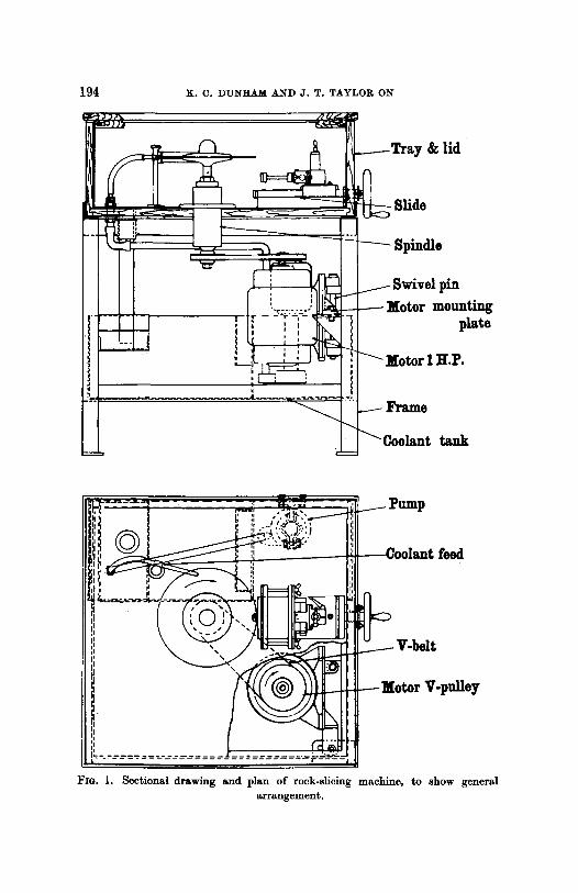
Designing of the new machine was commenced by Mr. Ward at Letchworth, but the work was later taken over by Mr. K. West and Mr. W. Shanks, who have bee n in charge on the drawing-office side.
The general layout is shown on fig. 1 and in the accompanying photo- graphs (figs. 2 and 3). The cutting-disk used is a 12-inch diameter 'Neven', manufactured by the Impregnated Diamond Company Ltd., of Gloucester. The thickness of the cutting edge is 0.08 inches (2.03 mm.) ~nd the width of the copper-bonded rim carrying the diamond powder
194 K. C. DUNHAM AND J. T. TAYLOR ON
lid
jin ounting
plate
[.P.
~nk
~ Pump
Ill FIo. 1. Sectional drawing and plan of rock-slicing machine, to show general
ar rangement .
DIAMOND-IMPREGNATED TOOLS FOR ROCK-SLICING 195
FIG. 2, Side view of rock-slicing machine with side covers removed.
Fro. 3. Photograph of rock-slicing machine from above.
1 9 6 K . C . DUN~AM AND J . T. TAYLOR ON
is 0"125 inches (3-15 ram.). The abrasive is 80-100 diamond grit. The disk is held by means of flanges 6 inches in diameter to a vertical spindle, to which it is locked by means of a left-hand threaded nut and cover. I t may be noted that complete rigidity and absence of end-play in the spindle are essential. These are ensured by the use of a spindle one inch in diameter, carried in Skefco bearings, a roller-race and a ball-race at the top (to deal with radial and end thrust), and a single heavy-duty deep- grooved race at the bottom. The spindle assembly is carried ~n a fabri- cated steel housing, to exclude abrasive rock-particles. The races are lubricated by a grease gun. Special grease-retaining washers, supplied by Skefco, are employed on the bearings.
The spindle is driven by a V-belt from a 220-volt direct current 1-0 horse- power motor, at a normal spindle speed of 1900 r.p.m. (= 6000 feet per minute peripheral speed). A field rheostat makes provision for increasing this speed to 2200 r.p.m.
The feed mechanism provides for both vertical and horizontal move- ment of the specimen-holding clamp, while the clamp itseff can be adjusted and set in a lateral and radial sense. The vertical movement is carried out by.a screw having 16 threads per inch. This is adjusted and locked in position before the cut is commenced. Horizontal motion towards the disk is provided by a robust left-hand threaded shaft, controlled by a hand-wheel on the front of the machine. As in the older machines, the specimen is caiTied between wood-lined jaws which grip it tightly ; the smallest movement of the specimen during cutting might lead to damage to the cutting-disk.
The lubricant employed for cutting is water with 30 fluid ounces of soluble off and 1 pound of soda per 9 gal]:ous. This is delivered to the cutting surface by jets above and below the cutting-disk, fed from a Varley type GS.455B submerged centrifugal suds pump installed in a tank in the lower part of the machine. The used coolant passes over a weir to allow rock particles to settle before it is returned to the tank. The cover of the cutting chamber is closed during operation, and observa- tion is facilitated by means of a hand-windscreen wiper.
Performance. All but very friable subjects can be cut by means of the high-speed
machine. A series of tests carried out by Mr. D. W. Hepp!e and Mr. G. H. Collins gave the comparison between the times taken to cut a 1-inch square chip from the same specimen by the manually armed and diamond-impregnated disk, which are summarized in the table below:
DIAMOND-IMPREGNATED TOOLS FOR ROCK-SLICING
Comparison of t imes taken to cut a 1-inch square chip, in seconds.
I t will be evident that there is a substantial saving in time; for the seven rocks tested, a little over 1 minute is compared with nearly 43 minutes for the older method. The maximum depth of cut obtained with the 12-inch disk is 3 inches, and specimens up to 5 inches wide can be held in the clamp, though a cut 3 inches deep over the full width is not obtainable. During tests a slice of chert 0.02 inch (0.51 ram.) thick was cut, and over the whole area of 2 square inches (12.9 square cm.) the maximum variation, in thickness was found to be 0.0004 inches (0.001 ram.) by micrometer measurement. The thickness of the chip which can be cut depends, however, on the nature of the rock. Chips mounted on glass slips with Canada balsam can be cut without difficulty on the machine. With normally hard rocks, cutting to a thickness of 1 mm. presents no difficulty. On present practice, the sectionis taken down from this stage on a glass plate with carborundum, or on the diamond-impregnated laps described below.
The possibility of using a section-holding clamp with micrometer adjustments in lateral ~and radial senses is now being investigated. By this means it is hoped to cut the chip, on the glass slice, to a thickness approaching that required for the final slice (0.03 mm.). This would represent an important step towards mechanical slice-making.
The machine has, at the time of writing, been in use for two years and has made not less than 5000 cuts. The cutting-disk shows very little evidence of wear, and given reasonable care in use, it appears that a long life may be expected for this tool under rock-cutting conditions.
Grinding-machines. Two diamond-impregnated grinding-laps are at present in use at the
Geological Museum. These a re mounted on metallographic polishing machines, consisting of 0.25 horse-power motors, vertically mounted,
1 9 8 K . C . DUNHAM AND J. T. TAYLOR ON
with the laps directly carried on the motor spindles. Cast iron casings round the laps give splash protection. The laps are supplied with coolant from the ~ n k and pump which supply the smaller cut-off disk. One of the laps, a 'Neven ' of Impregnated Diamond Co. manufacture, is 4 inches in diameter, with a cutting face 1.25 inches wide. This one con- rains 50-70 grade diamond grit, and rotates at 3400 r.p.m. The other, an older type, is 4 inches in diameter with a cutting face one inch wide, containing a finer grade of abrasive ; this lap runs at 2600 r.p.m. The laps prove very useful for trimming chips, and for the grinding stage in the case of hard rocks.
There is some evidence that wear on these is more rapid than on the cut-off disks, hut in daily use, providing that a sufficient supply of coolant is provided, several years of life may be expected with confidence. Manipulation of mounted chips takes rather more skill than on the slow- moving cast iron lap, but this can soon be acquired.
Other rock-cutting machines.
Recently a rock-slicing machine based on the prototype described here, incorporating a 12-inch diamond-impregnated disk, has been brought into commercial productio n by Sports Machines Ltd., of 373 Regents Park Road, London, N. 1. This includes also a grinding lap. The first tests have proved very satisfactory.
I t must also be mentioned that milling machines, incorporating vertically-mounted cut-off disks, are available on the market, for example, from the Impregnated Diamond Company. The addition of suitable clamps to the movable work-platform of such a machine would make it suitable for rock cutting. For sawing slices from long borehole cores such a machine would be particularly, useful. The main objection to the vertical mounting is the difficulty of preventing splashing of the coolant fluid.
Conclusion.
The use of diamond-impregnated cutting-disks mounted in a suitable machine gives substantially greater speed than with the manually armed type, the time spent in charging also being saved. Where a substantial programme of slicing is undertaken, it is probable that the cost compares favourably. Larger cuts and more precise control of cutting are obtained. The cut surfaces are smooth and free from macro- scopic grooves. Diamond-impregnated laps provide a means of rapid grinding. But notwithstanding the improvements here suggested in the
DIAMOND-IMPREGNATED TOOLS FOR ROCK-SLICING 199
mechanization of slice-making, the quality of the slices produced will still depend upon the manual skill of the slice-maker.
Acknowledgements.--The co-operative work done by members of the staffs of the Government Training Centre, and of the Geological Museum, mentioned in this note, is gratefully acknowledged. Gratitude is also expressed to successive managers of the Centre who have facilitated the work. We are desired by the present manager to add that shortage of engineering students makes i t impossible for him to accept further work of this sort at present.