Page 1
THE USE OF PULTRUDED GLASS FIBER REINFORCED POLYMER PROFILES IN
STRUCTURES
by
ELIAS A. POURLADIAN
B.S., Kansas State University, 2010
A REPORT
submitted in partial fulfillment of the requirements for the degree
MASTER OF SCIENCE
Department of Architectural Engineering and Construction Science
College of Engineering
KANSAS STATE UNIVERSITY
Manhattan, Kansas
2010
Approved by:
Major Professor
Kimberly Waggle Kramer, P.E., S.E.
Page 2
Abstract
Pultruded fiber reinforced polymer (FRP) shapes are gaining popularity in the
construction industry. Pultruded FRP profiles introduce a new world of construction that could
prove to be a viable option to traditional structural materials. The use of pultruded FRP profiles
in structures is discussed in this report. First a brief history of FRPs and their applications are
addressed before explaining in detail the two main components of FRP; fibers and resin. The
manufacturing process known as pultrusion and how two separate materials become one
structural member is examined. As a result of pultrusion, engineers and designers can create
structural profiles in customizable shapes, sizes, and strengths to suit any project and price.
Theoretically, a pultruded FRP profile can be customized to different strengths within the
geometrical and material bounds of the profile; however, many manufacturers publish data
regarding mechanical and thermal properties along with allowable loads for their nominal
profiles. Currently, there are no governing codes or guidelines for pultruded FRPs but there are
design manuals and handbooks published by various committees and manufacturers so the
design of pultruded FRP profiles is discussed. Ultimate and serviceability limit states are design
concerns that engineers always deal with but concerns of heat or fire, chemical or corrosion, and
moisture affect pultruded FRPs differently than steel or wood. Pultruded FRPs pose interesting
design concerns because increased customizability and workability means the member can be
tailored to meet the needs for that project but that would counter the benefit of mass-produced
nominal sizes. A lack of uniform codes and standards inhibits the growth of the pultrusion
industry in the United States but codes developed in Europe along with the development of
specialized agencies and organizations could help gain a foothold. Lastly, a set of beams varying
in length and load exhibit a side-by-side comparison to examine how pultruded FRPs match up
next to traditional building materials. Although wood, steel, and reinforced concrete have been
the preferred materials of construction, pultruded FRP structural shapes are gaining popularity
for its economical and physical advantages, and advances in manufacturing and technology stand
to usher in the widespread use of pultruded FRP profiles.
Page 3
iii
Table of Contents
List of Figures ................................................................................................................................. v
List of Tables ................................................................................................................................. vi
Acknowledgements ....................................................................................................................... vii
Dedication .................................................................................................................................... viii
CHAPTER 1 - Introduction ............................................................................................................ 1
Plastics ........................................................................................................................................ 1
Current Applications of Fiber Reinforced Polymers .................................................................. 2
CHAPTER 2 - Background of FRP ................................................................................................ 3
What is FRP? .............................................................................................................................. 5
Fibers ....................................................................................................................................... 5
Resins .................................................................................................................................... 11
Fillers & Additives ................................................................................................................ 12
Benefits & Weaknesses ......................................................................................................... 13
CHAPTER 3 - The Pultrusion Process ......................................................................................... 15
CHAPTER 4 - Material Properties ............................................................................................... 17
CHAPTER 5 - Design Considerations of FRP Shapes ................................................................. 23
Composite Action ..................................................................................................................... 23
Limit States ............................................................................................................................... 23
Ultimate Limit States ............................................................................................................ 24
Bending, Shear, & Bearing ............................................................................................... 24
Buckling ............................................................................................................................ 27
Serviceability Limit States .................................................................................................... 30
Deflections ........................................................................................................................ 30
Connections .............................................................................................................................. 31
Mechanical Connections ....................................................................................................... 31
Adhesive Connections .......................................................................................................... 32
Environmental Effects .............................................................................................................. 33
High Heat/Fire ...................................................................................................................... 33
Moisture/UV light ................................................................................................................. 34
Page 4
iv
Corrosion/Chemical Attack................................................................................................... 34
Design Applications .................................................................................................................. 34
Standards, Codes, and Testing .................................................................................................. 35
ASCE LRFD Standard for Pultruded FRP Structures .......................................................... 36
ASTM Testing ...................................................................................................................... 36
Manufacturers ....................................................................................................................... 37
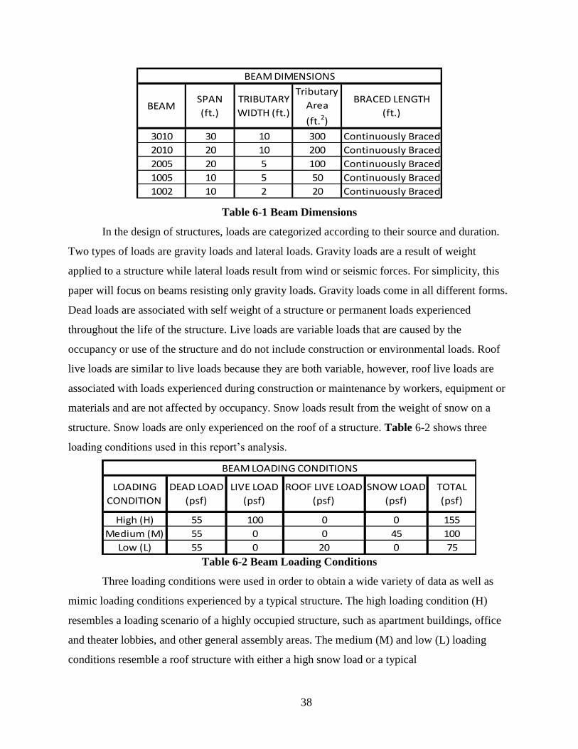
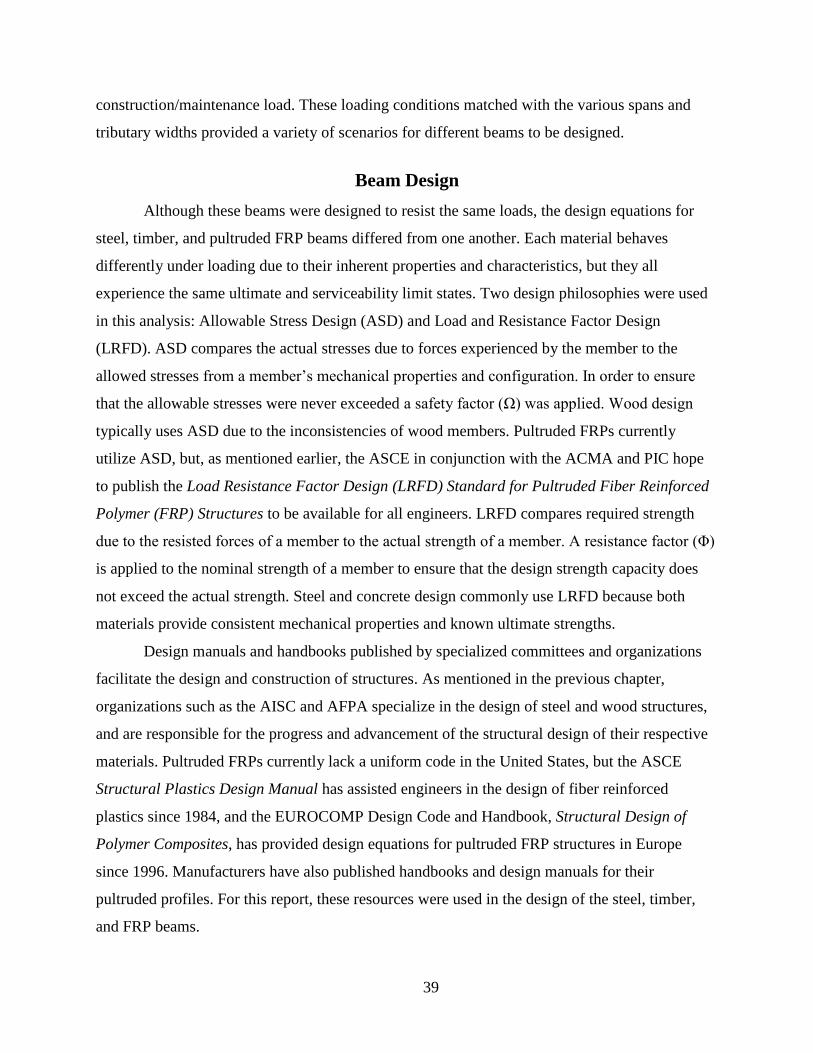
CHAPTER 6 - Beam Comparisons............................................................................................... 38
Beams and Loading Conditions ................................................................................................ 38
Beam Design ............................................................................................................................. 40
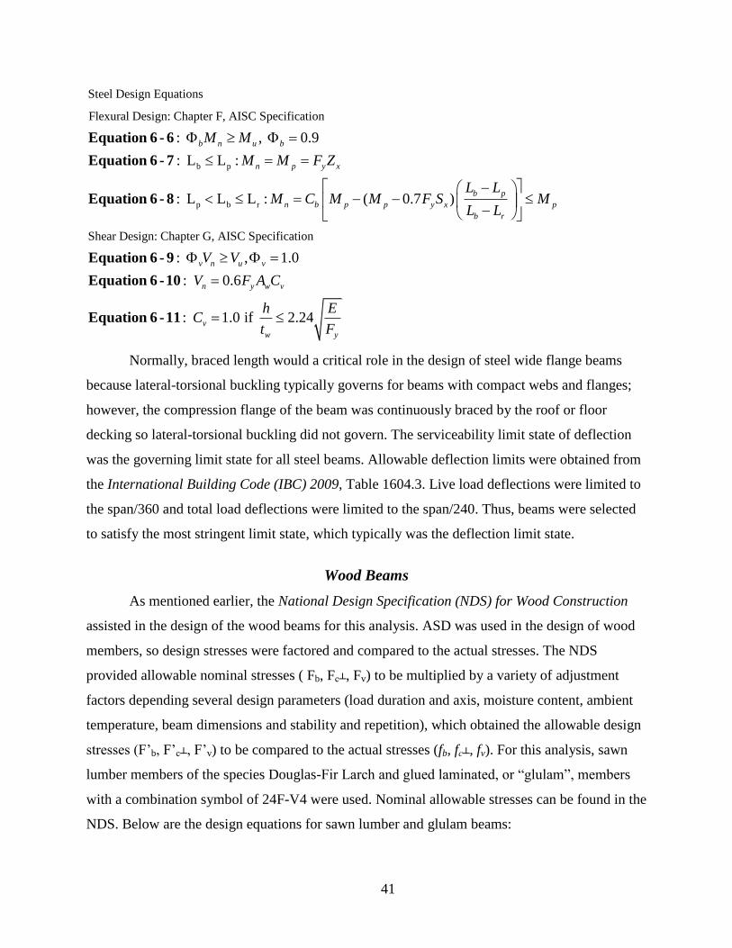
Steel Beams ........................................................................................................................... 41
Wood Beams ......................................................................................................................... 42
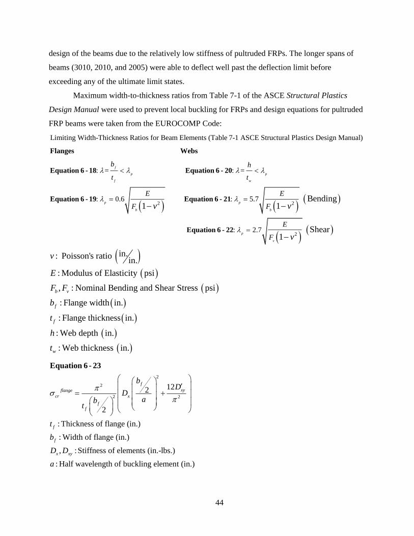
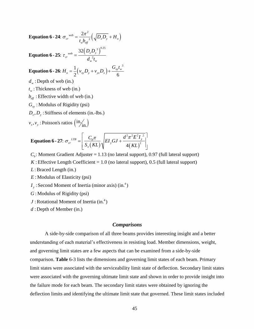
Pultruded FRP Beams ........................................................................................................... 44
Comparisons ......................................................................................................................... 46
CHAPTER 7 - Conclusion ............................................................................................................ 52
CHAPTER 8 - Works Cited .......................................................................................................... 53
Page 5
v
List of Figures
Figure 2-1 WWII Aircraft FRP Radome ........................................................................................ 3
Figure 2-2 Typical household fiber reinforced polymer products .................................................. 4
Figure 2-3 Fiberglass Manufacturing Process (Lubin, 1982) ......................................................... 8
Figure 2-4 Fiberglass roving ........................................................................................................... 9
Figure 2-5 a) Fiberglass chopped strand mat; b) Fiberglass woven fabric ..................................... 9
Figure 2-6 FRP Cross Section (Creative Pultrusions, Inc., 2002) ................................................ 10
Figure 2-7 Fabric Styles a) plain, b) twill, c) satin, d) unidirectional. (Structural Design of
Polymer Composites: EUROCOMP Design Code and Handbook, 1996) ........................... 11
Figure 3-1 Pultrusion Manufacturing Process of FRP Structural Member, (Strongwell
Corporation, 2008) ................................................................................................................ 15
Figure 4-1 Stress-Strain Curve for Steel ....................................................................................... 20
Figure 4-2 Stress-Strain Curve for Wood ..................................................................................... 21
Figure 4-3 Stress-Strain Curve for Typical Pultruded FRP .......................................................... 21
Figure 4-4 Stress-Strain Curve Comparisons ............................................................................... 22
Figure 5-1 Beam Loading and End Conditions ............................................................................ 25
Figure 5-2 Beam Stresses.............................................................................................................. 25
Figure 5-3 Geometric Strong and weak axes ................................................................................ 29
Figure 5-4 Buckling Examples ..................................................................................................... 29
Figure 5-5 Strong and weak axes of bending................................................................................ 29
Page 6
vi
List of Tables
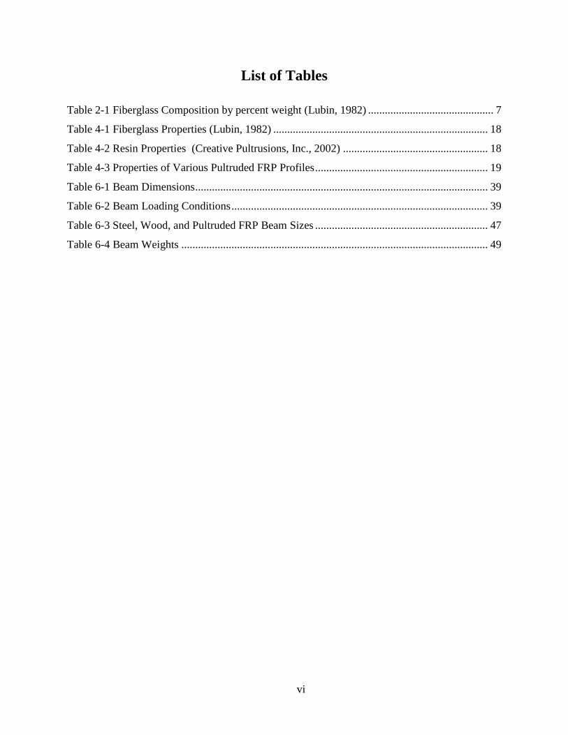
Table 2-1 Fiberglass Composition by percent weight (Lubin, 1982) ............................................. 7
Table 4-1 Fiberglass Properties (Lubin, 1982) ............................................................................. 18
Table 4-2 Resin Properties (Creative Pultrusions, Inc., 2002) .................................................... 18
Table 4-3 Properties of Various Pultruded FRP Profiles .............................................................. 19
Table 6-1 Beam Dimensions ......................................................................................................... 39
Table 6-2 Beam Loading Conditions ............................................................................................ 39
Table 6-3 Steel, Wood, and Pultruded FRP Beam Sizes .............................................................. 47
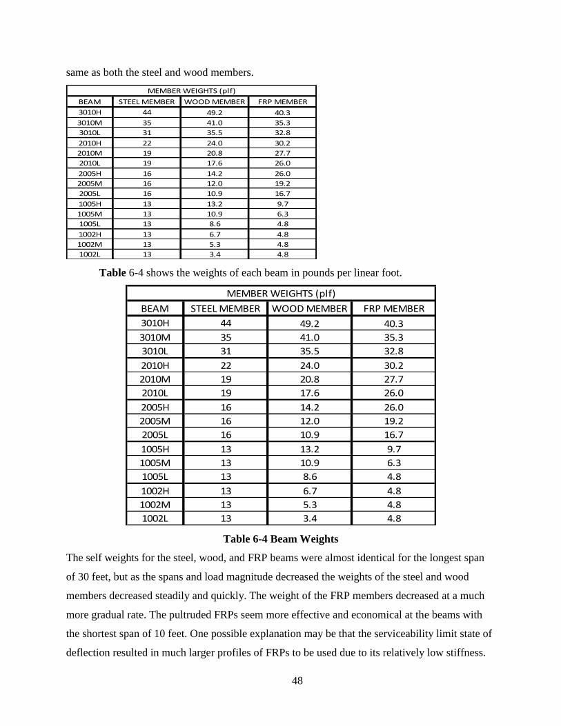
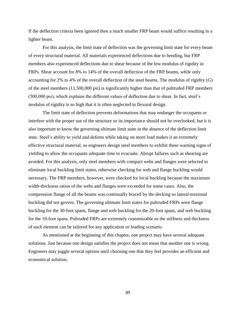
Table 6-4 Beam Weights .............................................................................................................. 49
Page 7
vii
Acknowledgements
First, I would like to thank my major professor, Kimberly Kramer, for her support
throughout my Master’s program. Kimberly was always available to answer questions, provide
direction and guidance, and give valuable words of encouragement that helped me complete this
report. Next, I’d like to thank my committee members Dr. Sutton Stephens, Ray Yunk, and Dave
Fritchen for their patience and helpful insight into my report. Finally, I’d like to thank Mr. John
Busel of the American Composites Manufacturers Association for providing me with
information regarding my topic.
Page 8
viii
Dedication
I’d like to dedicate this paper to my loving parents, Bamdad and Hilda, whose guidance
and support have undoubtedly helped me accomplish my goals. The amount of gratitude I owe to
them is incalculable.
Page 9
1
CHAPTER 1 - Introduction
Many different materials are used to create structures. Traditional materials like wood,
steel, concrete, and masonry have been the preferred materials for many years because their
strengths, weaknesses, and behaviors under stress are all well understood. The primary concern
in designing a structure is the safety of the structure’s occupants. With this in mind, engineers
must fully understand the materials used in a structure with regards to how it reacts under
loading and whether it is capable of resisting the forces during the life-span of the structure. All
the traditional materials mentioned above have withstood the test of time and proven themselves
to be reliable and efficient, but not without some trial and error. Only after research, analysis,
and testing of any new structural material can it be regarded safe to use for the public.
The ongoing search for more efficient and economical materials for construction has led
to the application of reinforced plastics used in structures. As intriguing as it may be to have an
entirely synthetic material become commonplace in construction, plastics must undergo the same
rigorous gauntlet of testing and analysis before becoming a viable option.
Plastics
In 2007, the plastics industry was the third largest manufacturing industry in the United
States. (Society of the Plastics Industry, 2009) The term plastics can cover a wide range of
materials. All plastics have common characteristics that classify them as a single group of
materials:
1.) They soften and can be formed into desired solid shapes with or without the use of
heat or pressure. This behavior is known as a plastic behavior.
2.) Their molecular structure is made of polymers. A polymer is a repetitive chain of
molecules, called monomers, which are bonded together.
3.) They are synthetic materials. This means they are man-made and do not occur in
nature.
Plastics are used in almost every industry and market sector. The past 100 years of research,
experimentation, and analysis, has enhanced plastics to better suit any application. As more time
is spent studying and altering plastics it will become more economically feasible to incorporate
them in the construction industry.
Page 10
2
From formwork used during construction to baseboards and moldings for aesthetic
purposes; plastics play an expansive role in structures. The versatility of plastic provides a
unique material suitable for almost every application. This paper will focus on the plastics used
for structural purposes; namely pultruded fiber reinforced polymers profiles.
Current Applications of Fiber Reinforced Polymers
In the recent decades, fiber reinforced polymers (FRP) have gained popularity in
structural applications for their many advantages over traditional construction materials. The
aerospace and automotive industries have taken advantage of FRP’s high strength to weight ratio
by designing entire chassis, fuselages, and wing structures using FRP. Advancements in the
technology and capabilities of manufacturing have increased the availability and feasibility of
FRP components that are better geared toward serving a specific purpose in a structure’s design.
FRP’s have been used as strips and wraps to strengthen pre-existing structures, and reinforcing
bars used to replace steel as the reinforcement in concrete or masonry. Similarly, the building
construction industry has utilized FRP’s advantages and identified a need for FRPs to be used in
structures.
Nonstructural elements, such as electrical cable trays, pipe supports, and
cladding/facades, are commonly made of FRP because of they can be easily customized to
accommodate any shape or size economically. FRP structural shapes are typically used in
structures that would be problematic for other construction materials. Extremely corrosive
environments such as marine/off-shore structures, water treatment facilities, power generation
cooling structures, and petro-chemical facilities require careful design and constant maintenance
to ensure a long and profitable life-span of the structure. FRP structures are highly resistive to
chemical corrosion in acidic environments whereas steel is susceptible to corrosion and wood
lacks the strength and resistance necessary for these structures. Electrical and communication
towers utilize FRP’s electrical non-conductivity and impede in radio transmissions less than a
steel structure would. Structures such as walkways, pedestrian bridges, and platforms benefit
from FRP’s low thermal conductivity as compared to steel’s and the resistance to decay, rot, and
insects unlike wood’s. The market for FRP structures is constantly growing as engineers,
designers, and manufacturers become more comfortable with FRPs.
Page 11
3
CHAPTER 2 - Background of FRP
The concept of composite materials can date back to ancient times when straw and twigs
were used to reinforce clay bricks. Separately, clay bricks and small limbs from plants used as
building materials have advantages and disadvantages. However, early humans learned that
combining the two materials creates a composite material that out-performs each separate
material. Steel reinforced concrete is one of the more successful and widely used composite
structural materials. More recently, the composite material industry has focused on composites
that are comprised of a polymeric resin and a fibrous reinforcement. In the early- to mid-1900s,
chemists and researchers began developing polymers that could be used in laminates for semi-
structural applications, such as the marine and aviation industries. These polymeric resins were
often layered with paper or cloth to create structural laminates used in these various applications.
Since then many types of resins with different chemical, thermal, and mechanical properties have
been created. In 1930, glass-fiber research was initiated by the Owens-Illinois and Corning Glass
Works (later becoming Owens-Corning Fiberglass Corporation) after a molten glass rod being
used to apply lettering on a glass milk bottle created a fine glass fiber, and 9 years later, the
Owens-Corning Fiberglass Corporation commercialized fiberglass to be used as insulation.
(Lubin, 1982) It wasn’t until the 1940s and World War II that fiberglass and polymeric resins
would be combined.
Figure 2-1 WWII Aircraft FRP Radome
The need for electromagnetically transparent radomes (domes that protected radar
antennae) sparked the combining of glass fibers and polymeric resin in the 1940s. The FRP
manufacturing industry gained significant notoriety during World War II when the government
issued contracts to fabricate semi-structural components for aircrafts made from resin and cotton
fibers. (Lubin, 1982) By the end of the war FRPs were successfully used in structural
Page 12
4
applications in aircrafts, automobiles, and boats. In the 1950s, the Corvette sports car featured a
fiberglass reinforced body that boasted lightweight agility coupled with structural stability and
strength. (Lubin, 1982) FRPs are now used in everyday household items such as bathtubs,
furniture, ladders, and tools. Prosthetics and other medical equipment also utilize FRP’s high
strength to weight ratio. FRPs are also used in recreational and sporting equipment such as,
tennis rackets, bicycles, golf clubs, skiing equipment, and fishing rods mostly due to the
inexpensive material costs. Many FRP manufacturing processes have been developed throughout
the years. Initially, the only method of manufacturing FRPs was by hand lay-up where a resin
coated mold of the desired product is layered with chopped fiberglass strands, mats, or fabric and
rolled to compact the material and remove entrapped air. This method was extremely labor
intensive, required a skilled technician, and had a low production rate. As technology advanced,
the manufacturing methods became more automated. Resin injection molds and pre-form
molding became popular because hardly any resin was wasted and efficiency was improved. In
the 1950s, W. Brant Goldsworthy developed a method known as pultrusion that manufactures
continuous lengths of an FRP member simply by mechanically pulling it through a heated die.
(Starr & Ketel, 2000)The versatility of FRPs is ever expanding, but one area in which it has not
gained wide spread popularity is in the construction industry.
Figure 2-2 Typical household fiber reinforced polymer products
As mentioned in the previous chapter, FRPs have been used in the construction industry
as reinforcing bars, wraps, and strips in concrete and masonry structures. The high tensile
strength and corrosion resistance give FRPs and advantage over the traditional steel
reinforcement used in these types of structures because improved durability and lower
maintenance cost result in a more economical structure without compromising strength and
Page 13
5
stability. Pultruded FRP structural profiles have become more accepted within the recent decades
due to increased understanding and evaluation of the characteristics of FRPs along with the
increased automation and access of raw materials required for economical FRP production.
Infrastructure, marine, electrical/communications, and petro-chemical processing structures are a
few of the applications that have benefitted from pultruded FRP members.
What is FRP?
FRPs typically consist of two man-made components; fibers and a polymeric resin. In
FRP members, synthetic reinforcing fibers are immersed in a polymeric resin and molded
together in a specific shape. The resulting matrix hardens by curing, often by heat, in the desired
configuration. FRP members can be manufactured in a variety of nominal or custom shapes and
sizes depending on the mold or die. This flexibility in the manufacturing process makes FRPs an
increasingly desirable structural material. Some benefits of having structural members comprised
of all synthetic materials are the availability of infinite customizable configurations/sizes, and
easily attainable design properties rather than the nominal run of the mill sizes and shapes.
Fibers
The fibers in FRPs provide the tensile strength throughout the member section, and can
be comprised of fiberglass, aromatic polyamide (aramid), or graphite (carbon) fibers. While
fiberglass is the most common fiber reinforcement used in pultruded FRP members, carbon and
aramid fibers are a high strength alternative. Carbon fibers are typically used in relatively small
structural applications that require high strength and stiffness. (Lubin, 1982) Aerospace and
automotive sectors utilize carbon fiber as well as recreational items such as fishing poles, tennis
rackets, and golf clubs. Aramid fibers, more commonly known as Kevlar, were originally created
by DuPont. (Lubin, 1982) Aramid is more commonly used in aerospace and military transports
as well as armor due to its high impact resistance. Carbon and aramid fibers are significantly
stronger than fiberglass, but they are also 10 to 30 times more expensive. (Gutowski, 1997)
While carbon and aramid fibers are used in smaller and more specialized FRP applications, large
scale production of pultruded FRP members tend to be more economically feasible when
fiberglass is used as the fiber reinforcement. The scope of this paper will focus on solely
fiberglass as the method of reinforcement in pultruded FRP members.
Page 14
6
The fiber reinforcement in FRPs exhibit strong tensile properties, but they are very weak
when loaded transversely. An FRP member is strong in resisting all directions of loading when
the reinforcing fibers span the member, both, longitudinally and transversely. For this reason
FRP members are anisotropic, which means that they exhibit unique characteristics depending on
the direction of loading. The direction of the reinforcing fibers is partially responsible for the
FRP member’s overall stability and strength.
All fiberglass reinforcement is comprised of silica (SiO2) but by itself SiO2 requires
extremely high temperatures to liquefy so modifiers are added to adjust the liquefying
temperature and control the characteristic properties. Precise proportions of modifiers, such as
aluminum oxide (Al2O3), boron oxide (B2O3), calcium oxide (CaO), magnesium oxide (MgO),
and sodium oxide (NaO) are heated to around 2,370°F (1,300°C), fused together, and drawn
through dies to form fiberglass filaments ranging in diameters from 1.5 x 10⁻⁴
inches (3.8 µm) to
94.5 x 10⁻⁴
inches (24 µm). (Bank, 2006) Different proportions of these chemical compounds
result in varying thermal and corrosion resistance properties.
Table 2-1 shows the percent weight of various chemical compounds in the different
grades of fiberglass.
The most common composition of fiberglass is high-alkali glass (A-glass). It provides
good chemical resistance, but struggles with electro-magnetic transparency. (Lubin, 1982) A-
glass can interfere with radio and electromagnetic waves such as cell-phone reception, which
could prove to be problematic for the occupants of a building. Low-alkali glass was developed to
improve electrical insulation in fiberglass and was therefore named E-glass. (Lubin, 1982) E-
glass exhibits most of the same properties of A-glass except much less electrical interference.
For extremely corrosive environments, C-glass was developed. C-glass behaves similar to A- and
E-glass, but provides unmatched resistance against chemical attack. Finally, S-glass was
developed for high-strength applications. The tensile strength in S-glass is 40% higher than that
of E-glass; therefore it is most widely used in special applications, such as the aircraft/aerospace
industry. (Lubin, 1982) Of all the grades of fiberglass available, E-glass is the grade most
commonly used in pultruded FRP profiles. It provides the best all-around performance and
durability.
Page 15
7
A
(HIGH ALKALI)
C
(CHEMICAL)
E
(ELECTRICAL)
S
(HIGH STRENGTH)
Silicon oxide 72.00 64.60 54.30 64.20
Aluminum oxide 0.60 4.10 15.20 24.80
Ferrous oxide - - - 0.21
Calcium oxide 10.00 13.20 17.20 0.01
Magnesium oxide 2.50 3.30 4.70 10.27
Sodium oxide 14.20 7.70 0.60 0.27
Potassium oxide - 1.70 - -
Boron oxide - 4.70 8.00 0.01
Barium oxide - 0.90 - 0.20
Miscellaneous 0.70 - - -
FIBERGLASS COMPOSITIONS (% wt.)
COMPONENTS
GRADE OF GLASS
Table 2-1 Fiberglass Composition by percent weight (Lubin, 1982)
After the fiberglass is made it can be spun into yarns, made into fabrics or mats, or
chopped into strands and shipped off to suit any number of purposes. Since Owen-Cornings’ first
commercially manufactured fiberglass in 1939, researchers and manufacturers have developed
grades of fiberglass with different properties each suited for different applications and
environments. Figure 2-3 illustrates the fiberglass manufacturing process.
Page 16
8
Figure 2-3 Fiberglass Manufacturing Process (Lubin, 1982)
Page 17
9
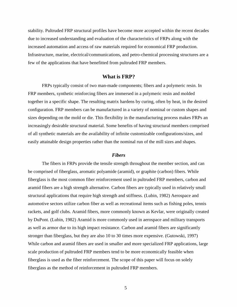
Figure 2-4 Fiberglass roving
Fiberglass filaments are the initial result of the fiberglass manufacturing process. The thin
glass filaments are spun into fiber strands, known as roving (Figure 2-4), and placed
unidirectionally to provide strength in one direction. In a pultruded shape, roving typically spans
the member longitudinally. The fiber filaments can also be woven or matted together to provide
strength in multiple directions. These are typically applied to the edges of a laminate or plate to
provide rigidity along the transverse axis of a member. Among the different fiber reinforcements
available in FRP members, fiberglass provides the most versatility because of its diverse
chemical make-up. The roving comprises 50% to 70% of the fiber content in the pultruded
member depending on the manufacturer and design specifications. (Bedford Reinforced Plastics,
Inc., 2009) Each roving filament is continuous throughout the member and provides the tensile
strength experienced when bending occurs. Due to the low transverse strength of fiberglass
filaments and the low shear modulus of the resin in pultruded members chopped or continuous
strand mats must be used to resist the shear and torsion forces.
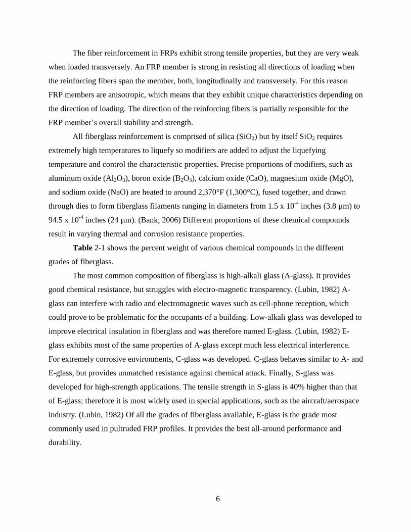
a) b)
Figure 2-5 a) Fiberglass chopped strand mat; b) Fiberglass woven fabric
Page 18
10
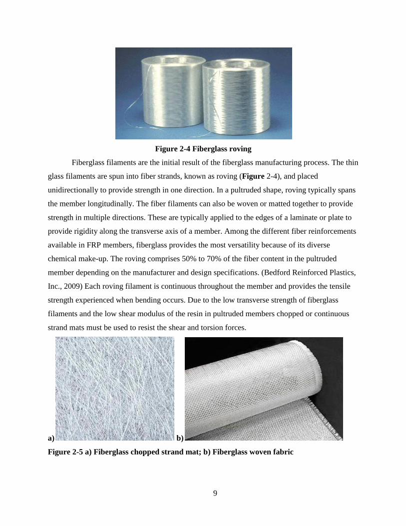
Figure 2-6 FRP Cross Section (Creative Pultrusions, Inc., 2002)
Continuous strand mats and/or fabrics are layered in the laminated plates, and provide the
resistance for loads in the transverse direction such as shear and torsion due to buckling.
Chopped strand mats are non-woven glass fiber strands that are chopped into short lengths and
fairly evenly distributed and randomly oriented. The random strand direction of chopped strand
mats ensure load transfer throughout the resin but provide little resistance to transverse loading
of the member. Fabrics, however, can provide the required resistance to transverse loads because
of the woven and interlocking orientation of the fibers. Fabrics can be woven into different styles
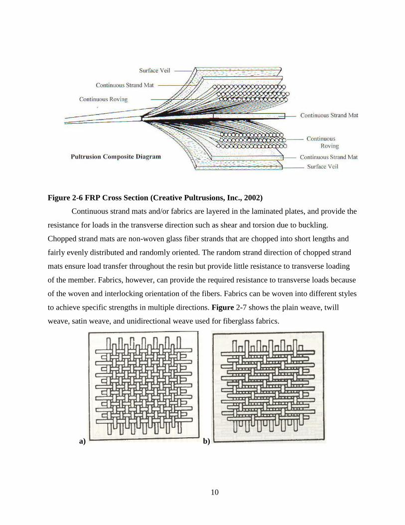
to achieve specific strengths in multiple directions. Figure 2-7 shows the plain weave, twill
weave, satin weave, and unidirectional weave used for fiberglass fabrics.
a) b)
Page 19
11
c) d)
Figure 2-7 Fabric Styles a) plain, b) twill, c) satin, d) unidirectional. (Structural Design of
Polymer Composites: EUROCOMP Design Code and Handbook, 1996)
Resins
Resins can be divided into two categories: thermoplastics and thermosets. Thermoplastics
are resins that can be repeatedly softened and hardened by heating and cooling the material. This
behavior is due to the chemical bond between polymers. Thermosets are resins that cannot be
softened after they have been hardened, or cured. This behavior is due to an irreversible chemical
process that occurs when the thermoset is cured.
Many resin mixtures can be utilized in an FRP pultruded structural member. Each resin
has unique characteristics or properties that may make it more suitable than other resins. Fire,
chemical, and environmental resistance are all factors that play a role in deciding which resin to
use when manufacturing an FRP pultruded structural member. All polymeric resin mixtures vary
in proportions of polymers, fillers, and additives. Typical resins include unsaturated polyesters,
vinyl esters, and epoxies. Each type of resin provides unique thermal, corrosion, and mechanical
properties that make them ideal in a certain application.
The most common polymer used in resins is unsaturated polyesters. Unsaturated
polyesters are used in 75% of the resins used in the United States of America mostly because
they are used in a variety of commercial products such as boats, bathtubs, ski poles, water slides,
and prefabricated paneling and floors. (Tang, 2010) Overall, unsaturated polyesters provide the
best value for performance and strength. Unsaturated polyesters possess properties that are very
well suited for the pultrusion process. Low viscosity promotes workability and thorough wetting
of the reinforcement, and high polymerization reactivity allows for quick but controllable curing
Page 20
12
within the pultrusion die. (Bogner, Breitigam, Woodward, & Forsdyke, 2000) Chemical and
additive alterations can be easily made with unsaturated polyesters, which can improve
mechanical properties and behavioral characteristics of pultruded FRP members.
Vinyl esters exhibit similar characteristics of unsaturated polyesters but are nearly 40%
more expensive. (Gutowski, 1997) However, vinyl esters provide better chemical resistance than
unsaturated polyesters. (Bogner, Breitigam, Woodward, & Forsdyke, 2000) Normally
unsaturated polyester would be the resin of choice for regular construction purposes (i.e. typical
commercial or residential building) but if the member is located in highly corrosive
surroundings, whether it is chemical, fire or environmental, then vinyl esters might be the best
decision. Vinyl esters are used in the same applications as unsaturated polyesters except with
higher concentrations and exposures to the aforementioned corrosive surroundings.
Epoxy resins are used for high-performance applications and not as common in pultruded
FRP members as polyesters and vinyl esters. They provide the highest level of strength,
durability, and fatigue and creep resistance Epoxy resins are almost exclusively used in
aerospace or defense applications with aramid or carbon fiber reinforcements due to its chemical
and thermal properties as well as its ability to adhere well to other materials. (Bogner, Breitigam,
Woodward, & Forsdyke, 2000) Epoxy resins, however, can cost 10 to 30 times the cost of
unsaturated polyester resins (Gutowski, 1997).
Fillers & Additives
Fillers and additives are mixed into the resin matrix to enhance or provide additional
properties. They can comprise of up to 30% of the weight of a structural member. (Structural
Design of Polymer Composites: EUROCOMP Design Code and Handbook, 1996) Fillers and
additives are designed to reduce material costs and peak exothermic temperature generated
during curing, lower shrinkage, increase resistance to environmental and fire exposure, increase
some properties (i.e. modulus of elasticity, hardness, etc.), enhance electrical transparency, and
alter the appearance (i.e. color, surface finish). Some common fillers and additives and their
respective roles are: clays and carbonates (shrinkage during curing), zinc oxide (pigment),
aluminum trihydrate, zinc borate (fire resistance), silanes and silicon-based chemicals (bonding
to reinforcement fibers). All fillers and additives are precisely portioned by the manufacturer to
achieve a specified product.
Page 21
13
Benefits & Weaknesses
When new materials immerge into the market it is important for them to prove to be
durable, economical and user friendly. These qualities will undoubtedly determine the amount of
success for any new material introduced. Structural engineers often select one type of material
over another for certain applications because they obtain characteristics, properties, or behaviors
that make them more suitable than other materials, however, ease of design and constructability
play an important role in the decision making process. The benefits and rewards of choosing a
relatively new material in structures must adequately justify the amount of work and effort put
into the design of the structure as engineers are hesitant to change. In order to effectively
determine whether a material is more suitable and desirable for a certain job the material’s
properties must be known and compared to other materials’. It is in this manner that the most
economical and structurally sound materials are chosen.
Fiber reinforced polymers have recently been gaining popularity among designers and
engineers for multiple reasons. Much of this popularity is due to the astonishing strength-to-
weight ratio of the FRP members. Pultruded FRP members are half as strong, but weigh 80%
less than their structural steel counterparts. (Strongwell Corporation, 2008) This could translate
to less dead load throughout the entire structure, which may help with reducing the member size
of the lateral force resisting system (LFRS) used to resist wind and seismic forces. Another
benefit of pultruded FRPs is the nonconductive nature of the material. Similarly to wood, FRPs
do not interfere with radio frequencies or electromagnetic waves. Steel and concrete are much
more dense and reflective of these waves, so cellular phone reception and radio frequencies are
not transmitted throughout a structure as easily. Electromagnetic transparency can be beneficial
when there needs to be an open channel of communication between many floors or walls. In an
FRP structure, a cellular device in the basement would be able to have great signal, whereas, in a
concrete or steel structure it may have difficulty getting a good signal. Corrosion resistance is
another advantage of using FRPs. Pultruded FRP profiles are extremely resilient in corrosive
environments. Pultruded FRP shapes with a vinyl ester or epoxy resin system are resistant to
most acidic and basic environments. Structures that contain volatile chemicals like chemical and
water treatment plants can benefit from pultruded FRP shapes because of the minimal
maintenance required in these harsh environments. One other benefit to pultruded FRP shapes is
the similar coefficient of thermal expansion to its steel counterparts. Extreme cold or hot
Page 22
14
surroundings shrink or expand structural members, so it is important to account for these
tolerances and make sure they are allowable for the design of the structure. Aesthetics aren’t
usually at the forefront of a structural engineer’s concern, but it is still an important factor that
goes into selecting a structural material for a building. Pultruded FRPs are extremely
customizable with the selection of the proper die during the pultrusion process. Of course a
thorough structural analysis of how the custom shape will resist load will be in order, but the
option of creating unique structural shapes is within reach. FRPs can also be manufactured in any
color with the addition of the appropriate dye at the beginning of the pultrusion manufacturing
process.
Pultruded FRPs show many advantages in being a formidable material in structures, but
there are some drawbacks to selecting them. While there is no flawless structural material,
engineers and designers cope with materials’ weaknesses by designing to avoid them while
emphasizing their strengths. Similar to wood, FRPs are extremely susceptible to fire damage and
other prolonged exposure to heat. Engineers and designers must account for situations that may
arise and properly design structures with the safety of the occupant in mind. A unique quality of
FRPs is its ability to extinguish itself in the event of a fire, whereas, wood is an extremely
combustible material and burns very easily. Another drawback of FRP composites is the mode of
failure. The reinforcing fibers and polymeric resins are extremely brittle. They tend to fail very
quickly and with little visible strain or yielding unlike steel. The application of safety factors to
design stresses ensures that pultruded FRPs will deform or buckle before rupture occurs.
Engineers safeguard against catastrophic failures by designing structural members to show some
form of warning to provide adequate time for evacuation. In steel design, the strain hardening
phase of the stress-strain diagram allows for noticeable deformation in the member to make the
occupants aware that the member is overstressed. The selection of structural material is an
important decision never to be overlooked. Engineers and designers must always make choices
based on facts and what they know is economically feasible and practical. When choosing a
material of construction they must know the benefits and detriments of their selection.
Page 23
15
CHAPTER 3 - The Pultrusion Process
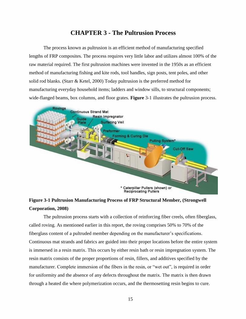
The process known as pultrusion is an efficient method of manufacturing specified
lengths of FRP composites. The process requires very little labor and utilizes almost 100% of the
raw material required. The first pultrusion machines were invented in the 1950s as an efficient
method of manufacturing fishing and kite rods, tool handles, sign posts, tent poles, and other
solid rod blanks. (Starr & Ketel, 2000) Today pultrusion is the preferred method for
manufacturing everyday household items; ladders and window sills, to structural components;
wide-flanged beams, box columns, and floor grates. Figure 3-1 illustrates the pultrusion process.
Figure 3-1 Pultrusion Manufacturing Process of FRP Structural Member, (Strongwell
Corporation, 2008)
The pultrusion process starts with a collection of reinforcing fiber creels, often fiberglass,
called roving. As mentioned earlier in this report, the roving comprises 50% to 70% of the
fiberglass content of a pultruded member depending on the manufacturer’s specifications.
Continuous mat strands and fabrics are guided into their proper locations before the entire system
is immersed in a resin matrix. This occurs by either resin bath or resin impregnation system. The
resin matrix consists of the proper proportions of resin, fillers, and additives specified by the
manufacturer. Complete immersion of the fibers in the resin, or “wet out”, is required in order
for uniformity and the absence of any defects throughout the matrix. The matrix is then drawn
through a heated die where polymerization occurs, and the thermosetting resin begins to cure.
Page 24
16
The curing process is carefully monitored with sensors and controls because it is the most crucial
part of pultrusion. Any defects result in a faulty unusable product. Once the pultruded member
has cured it is pulled along the line and cut into desired lengths. All of this occurs at an average
line speed of 3.3 ft (1 m) per minute. (Bogner, Breitigam, Woodward, & Forsdyke, 2000)
Pultrusion provides an effective and economical method of manufacturing a product with
consistent properties and a multitude of customizable options.
Environmental impact is out of the scope of this report but it is still a pertinent issue with
the manufacturing of building materials. Steel, wood, concrete, and masonry require different
amounts of resources and energy during the manufacturing process. Past research and analysis
has provided cost-benefit analyses for traditional materials that help engineers and designers in
the decision of a specific material for construction. The same must be done for pultruded FRP
profiles in order to justify the growth of the industry. Currently, initial costs of pultruded FRPs
are much higher than any other traditional structural material, but a life-cycle cost would take
into account the reduced cost of maintenance and protection in harsh environments. As pultruded
FRPs gain popularity life-cycle cost and cost-benefit analyses can provide more results regarding
the environmental impact of FRPs.
Page 25
17
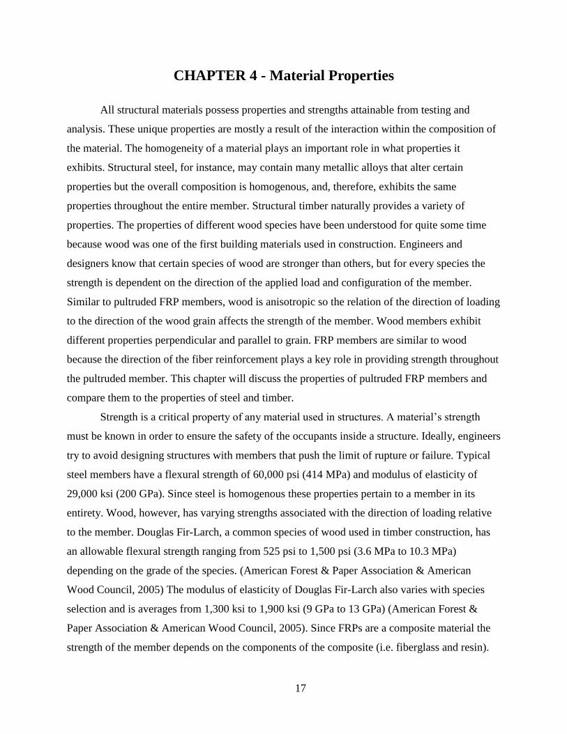
CHAPTER 4 - Material Properties
All structural materials possess properties and strengths attainable from testing and
analysis. These unique properties are mostly a result of the interaction within the composition of
the material. The homogeneity of a material plays an important role in what properties it
exhibits. Structural steel, for instance, may contain many metallic alloys that alter certain
properties but the overall composition is homogenous, and, therefore, exhibits the same
properties throughout the entire member. Structural timber naturally provides a variety of
properties. The properties of different wood species have been understood for quite some time
because wood was one of the first building materials used in construction. Engineers and
designers know that certain species of wood are stronger than others, but for every species the
strength is dependent on the direction of the applied load and configuration of the member.
Similar to pultruded FRP members, wood is anisotropic so the relation of the direction of loading
to the direction of the wood grain affects the strength of the member. Wood members exhibit
different properties perpendicular and parallel to grain. FRP members are similar to wood
because the direction of the fiber reinforcement plays a key role in providing strength throughout
the pultruded member. This chapter will discuss the properties of pultruded FRP members and
compare them to the properties of steel and timber.
Strength is a critical property of any material used in structures. A material’s strength
must be known in order to ensure the safety of the occupants inside a structure. Ideally, engineers
try to avoid designing structures with members that push the limit of rupture or failure. Typical
steel members have a flexural strength of 60,000 psi (414 MPa) and modulus of elasticity of
29,000 ksi (200 GPa). Since steel is homogenous these properties pertain to a member in its
entirety. Wood, however, has varying strengths associated with the direction of loading relative
to the member. Douglas Fir-Larch, a common species of wood used in timber construction, has
an allowable flexural strength ranging from 525 psi to 1,500 psi (3.6 MPa to 10.3 MPa)
depending on the grade of the species. (American Forest & Paper Association & American
Wood Council, 2005) The modulus of elasticity of Douglas Fir-Larch also varies with species
selection and is averages from 1,300 ksi to 1,900 ksi (9 GPa to 13 GPa) (American Forest &
Paper Association & American Wood Council, 2005). Since FRPs are a composite material the
strength of the member depends on the components of the composite (i.e. fiberglass and resin).
Page 26
18
Table 4-1 and Table 4-2 show the inherent properties of different resins and grades of fiberglass.
The combined properties result in a range of possibilities for pultruded FRPs dependent on the
ratio of fiber to resin in the member.
A C E S
psi x 103 440 440 500 665
MPa 3,033 3,033 3,448 4,585
psi x 106 - 10 10.5 12.4
GPa - 69.0 72.4 85.5
(in./in./°F) x 10-6 4.8 4.0 2.8 3.1
(mm/mm/°C) x 10-6 8.6 7.2 5.0 5.6
FIBERGLASS PROPERTIES
Property UnitsGrade of Fiberglass
Specific Gravity - 2.50 2.49 2.54 2.48
4.8 5.7
Coeff. of Thermal
Expansion
4.8
Tensile Strength
Tensile Modulus
Elongation % -
Table 4-1 Fiberglass Properties (Lubin, 1982)
Polyester Vinyl Ester Epoxy
psi x 103 11.2 11.8 11.0
MPa 77 82 76
psi x 103 17.8 20.0 16.7
MPa 123 138 110
psi x 106 0.43 0.54 0.47
GPa 3.0 3.7 3.2
°F 160 220 330
°C 71 104 166
RESIN PROPERTIES
Resin Types
Tensile Strength
Elongation % 4.5 5.0 6.3
Flexural Strength
Flexural Modulus
Heat Distortion
Temperature
Property Units
Table 4-2 Resin Properties (Creative Pultrusions, Inc., 2002)
Separately, fiberglass and resin make an inadequate structural material, but together they
can combine their strengths and prove to be a viable option in the construction industry. The
effectiveness of any FRP member relies on strand orientation and fiber content. The fiberglass is
primarily responsible for resisting force so the ratio of fiber to resin affects strength and strand
orientation affects stability. Pultruded FRP structural members typically have a tensile strength
of 30,000 psi (207 MPa) and a modulus of elasticity of 2,500 ksi (17.2 GPa). Of course, this
Page 27
19
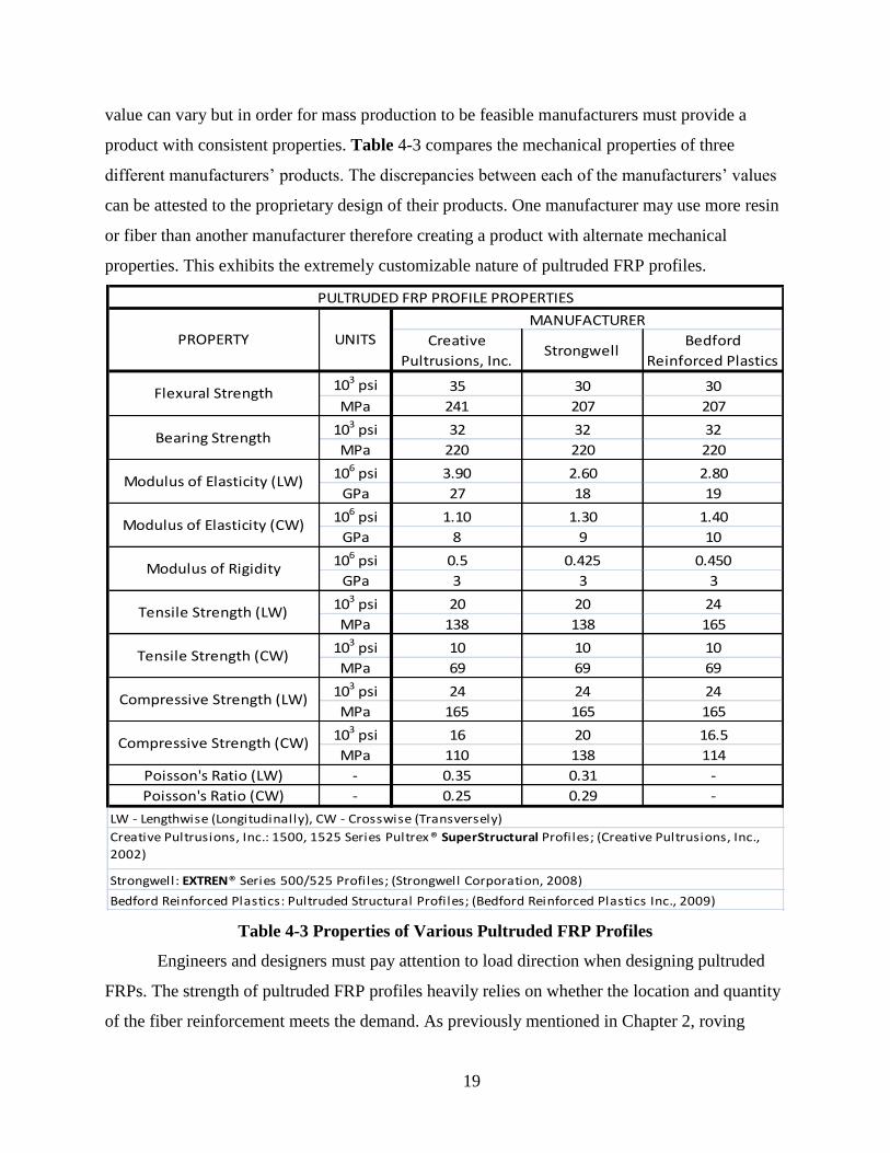
value can vary but in order for mass production to be feasible manufacturers must provide a
product with consistent properties. Table 4-3 compares the mechanical properties of three
different manufacturers’ products. The discrepancies between each of the manufacturers’ values
can be attested to the proprietary design of their products. One manufacturer may use more resin
or fiber than another manufacturer therefore creating a product with alternate mechanical
properties. This exhibits the extremely customizable nature of pultruded FRP profiles.
103 psi 35 30 30
MPa 241 207 207
103 psi 32 32 32
MPa 220 220 220
106 psi 3.90 2.60 2.80
GPa 27 18 19
106 psi 1.10 1.30 1.40
GPa 8 9 10
106 psi 0.5 0.425 0.450
GPa 3 3 3
103 psi 20 20 24
MPa 138 138 165
103 psi 10 10 10
MPa 69 69 69
103 psi 24 24 24
MPa 165 165 165
103 psi 16 20 16.5
MPa 110 138 114
Poisson's Ratio (LW) - 0.35 0.31 -
Poisson's Ratio (CW) - 0.25 0.29 -
PULTRUDED FRP PROFILE PROPERTIES
Bedford Reinforced Plastics: Pultruded Structural Profiles; (Bedford Reinforced Plastics Inc., 2009)
Tensile Strength (CW)
Compressive Strength (LW)
Compressive Strength (CW)
LW - Lengthwise (Longitudinally), CW - Crosswise (Transversely)
Creative Pultrusions, Inc.: 1500, 1525 Series Pultrex® SuperStructural Profiles; (Creative Pultrusions, Inc.,
2002)
Strongwell: EXTREN® Series 500/525 Profiles; (Strongwell Corporation, 2008)
Tensile Strength (LW)
PROPERTY UNITS
MANUFACTURER
Creative
Pultrusions, Inc.Strongwell
Bedford
Reinforced Plastics
Flexural Strength
Bearing Strength
Modulus of Elasticity (LW)
Modulus of Elasticity (CW)
Modulus of Rigidity
Table 4-3 Properties of Various Pultruded FRP Profiles
Engineers and designers must pay attention to load direction when designing pultruded
FRPs. The strength of pultruded FRP profiles heavily relies on whether the location and quantity
of the fiber reinforcement meets the demand. As previously mentioned in Chapter 2, roving
Page 28
20
provides longitudinal resistance and chopped strand mats and fabrics provide the transverse
resistance and stability. Manufacturers create pultruded profiles with ranging amounts of roving
and fabric so strength and stability may slightly vary for each product. Similar to steel and wood
entities, organizations and agencies involved with pultruded FRPs may dictate certain criteria
(fiberglass and resin grade, resin-fiber ratio, etc.) and minimum standards (flexural strength,
longitudinal and transverse moduli of elasticity, etc.) acceptable for mass production to help
develop a unifying code and progress the widespread use and design of pultruded FRP profiles.
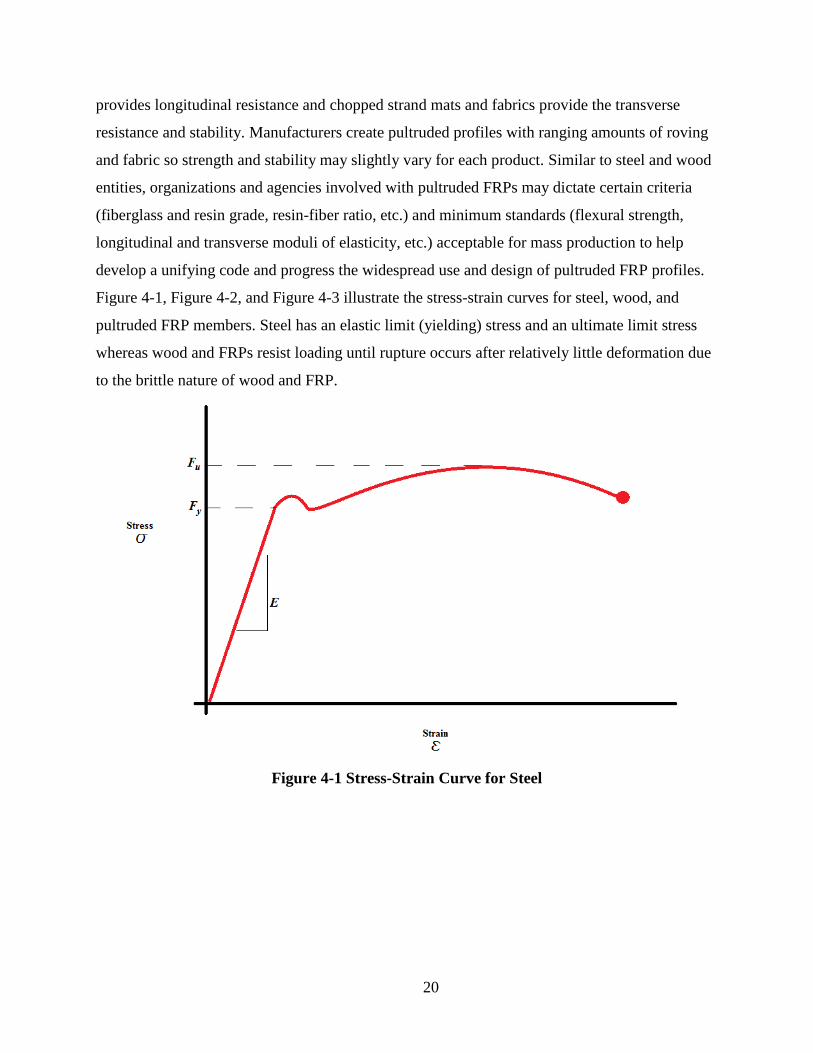
Figure 4-1, Figure 4-2, and Figure 4-3 illustrate the stress-strain curves for steel, wood, and
pultruded FRP members. Steel has an elastic limit (yielding) stress and an ultimate limit stress
whereas wood and FRPs resist loading until rupture occurs after relatively little deformation due
to the brittle nature of wood and FRP.
Figure 4-1 Stress-Strain Curve for Steel
Page 29
21
Figure 4-2 Stress-Strain Curve for Wood
Figure 4-3 Stress-Strain Curve for Typical Pultruded FRP
Page 30
22
Figure 4-4 Stress-Strain Curve Comparisons
Although the tensile strength of fiberglass (see Table 4-1) is considerably higher than
steel’s, the pultruded FRP beam is a composite comprising of resin and fiberglass so the
mechanical properties of the beam are a result of both of the components’ properties. The resin
and fiberglass content affect the properties. Exact values of strengths and stresses are proprietary
information depending on the manufacturer’s specification.
Page 31
23
CHAPTER 5 - Design Considerations of FRP Shapes
With the emergence of pultruded FRP shapes in structures, the need for a design standard
in the United States has increased. As FRP shapes become more readily available architects,
engineers, and contractors must have guidelines of how to design, specify, and construct
structures using FRP members. They cannot be creatively and technically confined by the
various manufacturers’ design handbooks and design methods. A uniform code that can be
widely accepted is the best method of expanding the growth of pultruded FRP shapes.
In order to create codes and standards, a full understanding of how the material acts under
loading must be achieved. This understanding is obtained through testing and, also, trial and
error. Codes and standards are constantly being modified and updated as the material becomes
more widely used. This chapter will focus on the design considerations of pultruded FRP shapes.
Composite Action
FRP structures are unique in their design because, unlike steel structures, they are not
considered a homogenous material. Pultruded FRP shapes utilize the strengths of two separate
materials; the tensile strength and low unit weight of the fibers and the stiffness and corrosion
resistance of the resin and this is why they are considered composite materials. Composite action
refers to the interaction and utilization of the properties of the separate materials. Reinforced
concrete is considered a composite material because the combination of the tensile and confining
strength of the reinforcing steel and the compressive strength of the concrete work together to
effectively resist loads better than unreinforced concrete.
Composite action is important to understand in FRP design because both elements, the
fibers and the resin, depend upon each other. Resins commonly used in pultruded FRP shapes
provide a strong bond with the reinforcing fibers, which allows the transfer of stresses
throughout the pultruded shape to be dispersed evenly with relatively low plastic deformation
and creep resistance. (Erhard, 2006). The success of a pultruded FRP member depends on the
load transfer between the fiber reinforcing, both longitudinal and transverse, and the resin.
Limit States
Every material acts in a specific manner when experiencing a load. This behavior can
sometimes determine whether the material is suitable for a certain design application. A
Page 32
24
material’s characteristic properties determine how that material will behave when loaded. A
material’s mode of failure is dependent on the geometric shape, size, and mechanical properties
characteristic of that material; modulus of elasticity (E), the modulus of rigidity (G), and ultimate
strength. Structural materials fail when a limit state, a state when the structure no longer satisfies
its design requirements, has been reached. There are two types of limit states: ultimate limit state
and serviceability limit state.
Ultimate Limit States
Ultimate limit states result from the behavior of the member under excessive loading.
Ultimate limit states are normally associated with collapse, rupture, or other structural failures
that may endanger the equilibrium of the structure or the safety of the occupants. A material’s
mechanical properties determine whether the ultimate limit states are easily exceeded. Engineers
try to avoid ultimate limit states that occur abruptly by designing structures to exhibit warning
signs (deformations, cracking, and delaminations) to allow the occupant adequate time to exit the
structure. By selecting the appropriate sizes and configurations of structural members that can
effectively resist loads and avoid reaching these limit states.
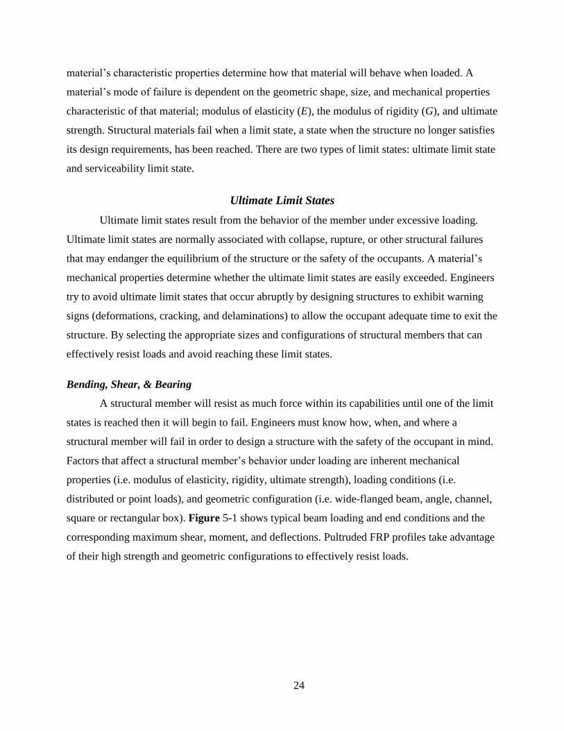
Bending, Shear, & Bearing
A structural member will resist as much force within its capabilities until one of the limit
states is reached then it will begin to fail. Engineers must know how, when, and where a
structural member will fail in order to design a structure with the safety of the occupant in mind.
Factors that affect a structural member’s behavior under loading are inherent mechanical
properties (i.e. modulus of elasticity, rigidity, ultimate strength), loading conditions (i.e.
distributed or point loads), and geometric configuration (i.e. wide-flanged beam, angle, channel,
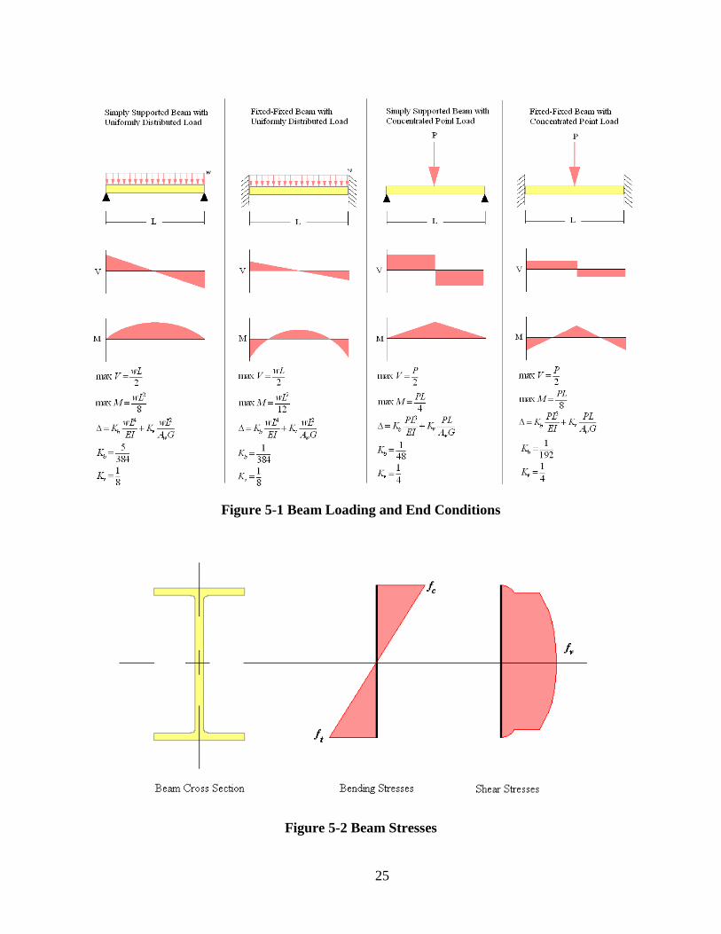
square or rectangular box). Figure 5-1 shows typical beam loading and end conditions and the
corresponding maximum shear, moment, and deflections. Pultruded FRP profiles take advantage
of their high strength and geometric configurations to effectively resist loads.
Page 33
25
Figure 5-1 Beam Loading and End Conditions
Figure 5-2 Beam Stresses
Page 34
26
The primary purpose of a beam is to resist bending forces. A bending stress involves a
compression stress, typically at the top section of a profile, and a tensile stress at the bottom as
shown in Figure 5-2. The actual bending stress (fb) is a result of the load applied to the beam.
The allowable bending stress (F’b) is the bending stress that a specific member can resist. For
pultruded FRP, manufacturers and industry organizations apply a safety factor of 2.5 to the
allowable bending stress to safely ensure that limit is never exceeded otherwise an accidental
catastrophic failure could occur. (Structural Design of Polymer Composites: EUROCOMP
Design Code and Handbook, 1996) The allowable bending stress is designed to be greater than
the actual bending stress.
: Moment (lbs.-in.)
b v c
w b
M V Rf f f
S A A
M
Equation 5 -1 Equation 5 - 2 Equation 5 - 3
3 2 2
:Shear (lbs.) : Reaction at support (lbs.)
:Section Modulus (in. ) : Area of the web (in. ) : Bearing Area (in. )w b
V R
S A A
Shear stresses involve tearing of a structural material in opposite directions. Beams
experience shear as a result of the resisted loads. The web element of I-beams resist shear. Actual
shear stress (fv) is the result of the reaction at each support with the loading on the member. The
maximum shear on a member generally occurs at one of the supports. The allowable shear stress
(F’v) must exceed the allowed shear stress. A safety factor of 3.0 is typically applied to the
design shear stress because shear abruptly fails and provides no visual indication of failure to
notify the occupants. (Creative Pultrusions, Inc., 2002) The modulus of rigidity (G) measures a
material’s ability to resist shear.
Bearing stresses involve crushing of the surface of the member due to high concentrated
loads. This normally occurs at the supports of a simply supported beam. The bearing area and
compressive strength of a material are critical to calculating the allowed bearing stress (F’c). A
larger bearing area results in a larger F’c. A safety factor of 2.0 is applied to the F’c. (Creative
Pultrusions, Inc., 2002) The actual bearing stress (fc) involves the reaction at the support as a
result of the loaded beam.
The first and foremost main objective of a structural member is to resist load, and the
manner in which it accomplishes this correlates with the magnitude and intensity of the load, the
mechanical properties inherent to that member, and the geometric configuration. However, in the
Page 35
27
design of pultruded FRP shapes, the ability to resist load may not be the prevalent issue due to
the high strength of the material. Buckling, excessive deflections, minor cracking, local failures,
and aesthetics usually play a governing role in the design.
Buckling
Buckling is the limit state of sudden failure of a structural member or element due to high
compressive stresses. Dimensional stability is a key component of a structural member’s ability
to resist buckling. The stiffness and configuration of a beam’s elements determine its strong and
weak axes. A wide-flange is an ideal member for beams, girders, and other flexural members
because the flanges effectively resist the high compressive and tensile forces associated with
flexure and the web resists shear. However, a member’s rigidity also plays a significant role. The
modulus of elasticity (E) measures how well a material can deform and return to its normal state
after a force has been applied and removed. Steel has a relatively high modulus of elasticity of
29,000 ksi (200 GPa), while wood has a lower modulus of elasticity of approximately 1,000 ksi
(7 GPa). A pultruded FRP member has a modulus of elasticity of 3,000 ksi (20 GPa)
longitudinally and 100 ksi (7.5 GPa) transversely (See
103 psi 35 30 30
MPa 241 207 207
103 psi 32 32 32
MPa 220 220 220
106 psi 3.90 2.60 2.80
GPa 27 18 19
106 psi 1.10 1.30 1.40
GPa 8 9 10
106 psi 0.5 0.425 0.450
GPa 3 3 3
103 psi 20 20 24
MPa 138 138 165
103 psi 10 10 10
MPa 69 69 69
103 psi 24 24 24
MPa 165 165 165
103 psi 16 20 16.5
MPa 110 138 114
Poisson's Ratio (LW) - 0.35 0.31 -
Poisson's Ratio (CW) - 0.25 0.29 -
PULTRUDED FRP PROFILE PROPERTIES
Bedford Reinforced Plastics: Pultruded Structural Profiles; (Bedford Reinforced Plastics Inc., 2009)
Tensile Strength (CW)
Compressive Strength (LW)
Compressive Strength (CW)
LW - Lengthwise (Longitudinally), CW - Crosswise (Transversely)
Creative Pultrusions, Inc.: 1500, 1525 Series Pultrex® SuperStructural Profiles; (Creative Pultrusions, Inc.,
2002)
Strongwell: EXTREN® Series 500/525 Profiles; (Strongwell Corporation, 2008)
Tensile Strength (LW)
PROPERTY UNITS
MANUFACTURER
Creative
Pultrusions, Inc.Strongwell
Bedford
Reinforced Plastics
Flexural Strength
Bearing Strength
Modulus of Elasticity (LW)
Modulus of Elasticity (CW)
Modulus of Rigidity
Page 36
28
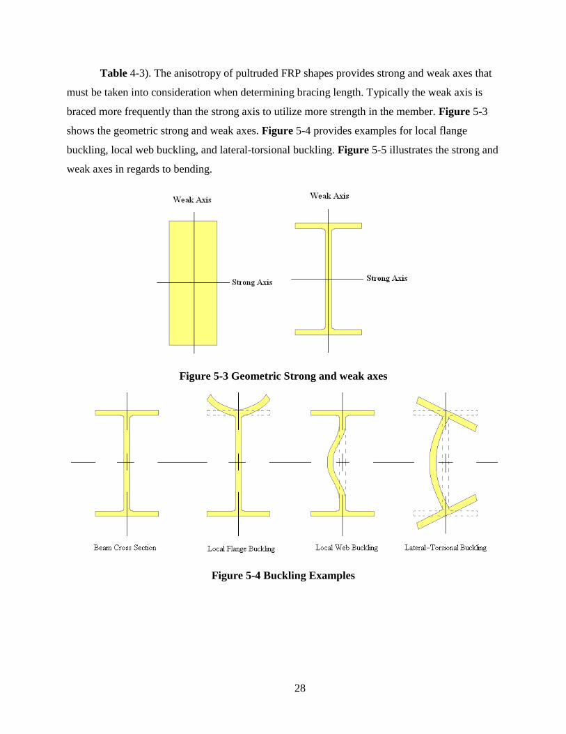
Table 4-3). The anisotropy of pultruded FRP shapes provides strong and weak axes that
must be taken into consideration when determining bracing length. Typically the weak axis is
braced more frequently than the strong axis to utilize more strength in the member. Figure 5-3
shows the geometric strong and weak axes. Figure 5-4 provides examples for local flange
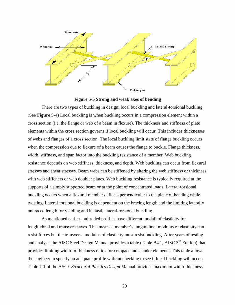
buckling, local web buckling, and lateral-torsional buckling. Figure 5-5 illustrates the strong and
weak axes in regards to bending.
Figure 5-3 Geometric Strong and weak axes
Figure 5-4 Buckling Examples
Page 37
29
Figure 5-5 Strong and weak axes of bending
There are two types of buckling in design; local buckling and lateral-torsional buckling.
(See Figure 5-4) Local buckling is when buckling occurs in a compression element within a
cross section (i.e. the flange or web of a beam in flexure). The thickness and stiffness of plate
elements within the cross section governs if local buckling will occur. This includes thicknesses
of webs and flanges of a cross section. The local buckling limit state of flange buckling occurs
when the compression due to flexure of a beam causes the flange to buckle. Flange thickness,
width, stiffness, and span factor into the buckling resistance of a member. Web buckling
resistance depends on web stiffness, thickness, and depth. Web buckling can occur from flexural
stresses and shear stresses. Beam webs can be stiffened by altering the web stiffness or thickness
with web stiffeners or web doubler plates. Web buckling resistance is typically required at the
supports of a simply supported beam or at the point of concentrated loads. Lateral-torsional
buckling occurs when a flexural member deflects perpendicular to the plane of bending while
twisting. Lateral-torsional buckling is dependent on the bracing length and the limiting laterally
unbraced length for yielding and inelastic lateral-torsional buckling.
As mentioned earlier, pultruded profiles have different moduli of elasticity for
longitudinal and transverse axes. This means a member’s longitudinal modulus of elasticity can
resist forces but the transverse modulus of elasticity must resist buckling. After years of testing
and analysis the AISC Steel Design Manual provides a table (Table B4.1, AISC 3rd
Edition) that
provides limiting width-to-thickness ratios for compact and slender elements. This table allows
the engineer to specify an adequate profile without checking to see if local buckling will occur.
Table 7-1 of the ASCE Structural Plastics Design Manual provides maximum width-thickness
Page 38
30
ratios to prevent local buckling for pultruded FRP profiles; however, the highly customizable
nature of pultruded profiles requires that local buckling of the flanges and webs are checked.
Serviceability Limit States
Serviceability limit states are associated with excessive deformations or deflections that
affect the appearance or use of the structure. Serviceability limit states also include excessive
vibrations or local damage (i.e. buckling, delamination, cracking).
Deflections
Deflections cause movement of a structural member which can lead to cracking of
masonry or stone facades or warping of surfaces. A structural member deflects as it resists a
load. This deflection depends on the intensity of the load and the stiffness and configuration of
the member and beam conditions. (See Figure 5-1) Pultruded FRP shapes have a relatively low
modulus of elasticity, so deflection typically governs the design and specification of members.
Deflection is designated as delta (Δ). Pultruded FRP members take into account deflection due to
shear because the low shear modulus (modulus of rigidity) significantly contributes to the overall
deflection especially in shorter span beams. The modulus of rigidity (G) is a ratio of the pressure
applied transversely a material and measuring the lateral displacement, whereas, the modulus of
elasticity (E) is a ratio of tensile pressure and longitudinal displacement. Steel is such a rigid
material that the deflection due to shear is negligible so it is ignored in this calculation. Structural
wood design tables include the effects of shear deflection in the modulus of elasticity values,
therefore eliminating the need to calculate shear deflection for wood members. (American Forest
& Paper Association & American Wood Council, 2005)
Connections
Arguably the most critical points of a structure are the connections. Connection design is
important because an inadequate connection design could result in a catastrophic failure of the
entire structure. Connections are designed to transfer loads between members so they must be
stronger than the members. Pultruded FRPs pose interesting options for connections. Two
categories of connections are mechanical and adhesive. A combination of the mechanical and
adhesive connections is also common. These connections are responsible for keeping the
structure intact and stable.
Page 39
31
Mechanical Connections
Mechanical joints involve the joining of two or more laminates or plates with fasteners
which transfer the load from one structural member to another. The number and spacing of
fasteners affects the strength of the connection. FRP connection design is similar to other
traditional materials’ because limit states like bearing, tensile, shear, and fastener failure govern.
Design parameters such as geometry of the connection, fastener diameter, plate thickness, and
loading condition should be taken into account when designing a mechanical connection. In FRP
connection design, the anisotropy of a plate plays a crucial role because the connection might
have multiple scenarios with varying load direction. Each plate and web or flange of a beam
must be designed to resist all foreseeable forces. FRP connections require fasteners to be either
stainless steel or FRP because components in the resin matrix can cause corrosion to occur
within the joint. Corrosion of the fasteners can jeopardize the structural integrity of a connection.
Mechanical connections are easier to construct because the tools needed are readily
available and the connections can be prefabricated or created on the construction site. Much like
wood pultruded FRP profiles can be sawn or drilled by using carbide tipped power tools.
(Strongwell Corporation, 2008) A certain amount of quality control is necessary but does not
require someone to be professionally licensed. Mechanical joints are easy to inspect and can be
disassembled, however efficiently distributing the load can be difficult due to the anisotropy of
the plate and member elements and attaching the connection can be rather time consuming.
Adhesive Connections
Adhesive connections, also known as bonded joints, join two adherends with the use of
an epoxy adhesive where load transfer occurs. When applied correctly, adhesive joints provide
far superior strength than mechanical joints because the surface area of the connection is larger.
A larger connection, or lap length, results in a stronger connection. Other factors that affect the
strength of a connection are adhesive thickness and fiber orientation of the adjoining adherends.
Again, the anisotropic nature of FRPs plays a crucial role in the design so engineers must be
fully aware of all loading scenarios. There are three failure modes for bonded joints: adhesive
failure, cohesive failure of the adhesive, and cohesive failure of the adherend. Adhesive failure
occurs when the adhesive bond fails and causes a separation between the adherend and adhesive.
This is most likely due to inconsistent materials or inadequate surface preparation. Cohesive
Page 40
32
failure of the adhesive occurs when a load exceeding the adhesive strength causes it to fail.
Cohesive failure of the adherend occurs when a load exceeding the adherend strength causes it to
fail. (Structural Design of Polymer Composites: EUROCOMP Design Code and Handbook,
1996) Engineers design connections to exceed loads resisted by the members they support in
order to dictate a governing limit state stay with the design of the beam (i.e. deflection or lateral-
torsional buckling).
Quality control is very important with bonded joints. If the entire structure has been
planned and finalized then having the connections prefabricated in a closed environment rather
than on the construction site might be a feasible option. Surface preparation of an FRP plate
involves chemical solvents and abrasive cleaning to expose the outermost fibers. Careful
application of the adhesive requires precise dimensions and locations along with a steady hand
all while the surface stays clean, which can be near impossible on a construction site. Adhesive
thickness is crucial because any variation could cause a decrease in strength or misalignment.
Curing of the adhesive could take some time so the connection might have to be temporarily
braced or clamped. Also, curing may require excess heat or cause an exothermic reaction. There
are many fine intricacies involved with the proper application of an adhesive connection.
Environmental Effects
Structural materials are often chosen because of environmental effects. Environmental
effects pertain to the outdoor or indoor conditions that the member might come in contact. Such
conditions can severely inhibit performance or durability. High heat, fire, moisture, chemical,
UV ray degradation, rot and decay are all environmental effects that must be taken into
consideration when designing any structure.
High Heat/Fire
Heat and fire are the great destroyers. Heat can attribute to deterioration and degradation
of a material, almost anything becomes destroyed in a hot enough fire. Pultruded FRP shapes
have a coefficient of thermal expansion of 7 x 10⁻⁶
in./in.°F (Strongwell Corporation, 2008),
which is near steel’s coefficient of thermal expansion of 6.5 x 10⁻⁶
in./in.°F (Simmons, 2001) so
deflections due to temperature variances are similar to one another. The change of temperatures
with the seasons causes materials to expand and contract, which can introduce stresses and
deformations in a structure. Certain tolerances within critical areas of a structure ensure that no
Page 41
33
damage results from thermal deformations. Fire resistance, flammability, fire propagation, heat
generation, smoke emission, and toxic and noxious fumes can factor into the effectiveness of a
structural material’s performance during a fire. More importantly, a structural material’s strength
retention while exposed to high heat or fire plays an important role in the safety rating and
reliability of a structural material. When exposed to elevated temperatures of 100°F, 125°F, and
150°F pultruded FRPs retain 90%, 85%, and 80% of their strength for vinyl ester resin systems
and 85%, 70%, and 50% for polyester resin systems, respectively. (Strongwell Corporation,
2008) This is a drastic drop in strength and one of the main reasons many engineers shy away
from designing FRP structures. In wood design, a prolonged exposure to 150°F temperature
merits a 0.7 or 0.9 reduction factors in strength. (American Forest & Paper Association &
American Wood Council, 2005) Steel retains 100% of its strength in temperatures as high as
750°F and 50% of its strength at 1100°F (AISC, 2005). In addition to their destructive nature
fires create smoke which may contain harmful compounds that the occupants might inhale as
they exit the building. Fire resistance for pultruded FRPs may involve a surface coating or
certain fillers and additives within the resin making them self extinguishable or smokeless when
exposed to an open flame. Fire suppression or isolation of the overall design of the structure with
the use of fire sprinklers and adequate fire ratings on partitions greatly reduces the danger of
damage and failure due to fire.
Moisture/UV light
Moisture and UV light degradation affect the resin matrix. Moisture is important because
it has the potential of reducing strength within the resin matrix or causing other issues such as
mold or corrosion. Resin polymers are extremely susceptible to moisture degradation. This issue
is amplified when a composite material is in question because the strength of one of the
components is dependent on the other. Adequate moisture and UV protection is achieved with a
resin matrix with no imperfections and shielded with a surface veil.
Corrosion/Chemical Attack
Some of the most hostile environmental effects involve corrosion or chemical attack.
Corrosion can obliterate a steel structure to scrap with the right amount of moisture and time.
Fortunately, FRPs are highly known to resist corrosion. The engineer or designer should be
Page 42
34
aware whether an FRP member will ever endure highly corrosive or chemical environment
because it may influence the grade of fiberglass and resin matrix required.
Design Applications
A structure must be designed to resist loads it will experience in its life cycle. Whether
these loads are due to the self weight of the structure (dead loads), the weight of the structure’s
occupants and equipment (live loads), environmental forces (rain, snow, soil), and lateral forces
(wind, seismic) every engineer and designer must come up with a solution to successfully and
safely resist the loads with the construction materials that are available. However, some
structural materials may effectively resist loads experienced in the life of the structure, but they
may not be the best choice due to the surrounding environment. Certain materials are very
unfavorable in harsh environments. Marine applications deal with elevated levels of salt water,
which is extremely corrosive to steel. Chemical and petroleum processing plants are almost
immersed in harmful chemicals that can degrade most of the conventional structural materials.
These design scenarios involve intensive maintenance to ensure no structural elements have been
compromised.
Standards, Codes, and Testing
Codes and standards govern the design of structures. All structural materials have a
governing code or standard that engineers and designers follow in order to design a safe and
stable structure. These codes and standards are normally written by committees and agencies that
specialize in and understand the structural material. Each country has its own governing bodies
that regulate the codes and standards of structural materials. In the United States, for instance,
the main four structural materials (wood, concrete, masonry, and steel) have their separate
entities that publish codes and standards. The American Institute of Steel Construction Inc.
(AISC) publishes the Steel Construction Manual, which assists engineers in the design of steel
structures. For wood, the American Forestry & Paper Association (AFPA) publishes the National
Design Specification (NDS) for Wood Construction. The NDS provides engineers and designers
with standards and specifications that must be followed in order to design a structure that will
maintain its structural integrity and provide for the safety of the occupants throughout the
structure’s life span. The American Concrete Institute (ACI) publishes many codes that are used
Page 43
35
by engineers for the design of concrete structures. Similar to the AFPA and other agencies
associated with structural materials, the ACI is divided into committees and subdivisions that
specialize in certain areas of the industry, such as materials and properties, design and
construction, and special applications. Masonry design is governed by the Masonry Standards
Joint Committee, which is comprised of the ACI, The Masonry Society (TMS), and American
Society of Civil Engineers (ASCE). The ASCE publishes technical guidelines, codes, and
standards that engineers follow to ensure safety and promote reliability and efficiency.
Although FRP pultruded shapes are relatively new in today’s construction methods there
are many agencies that are hard at work developing a better understanding of FRPs and how they
can be used in structures. In industry, progress is a very slow process but eventually every
engineer or designer will benefit from the work of these agencies and be able to safely design
FRP structures. Past design manuals, such as the ASCE Structural Plastics Design Manual and
the EUROCOMP Structural Design of Polymer Composites Design Code and Handbook have
been the main resource in the design of pultruded FRP structures. The 2009 International
Building Code by the International Code Council (ICC) provides standards for fire safety and
load information for the design of fiberglass reinforced polymers, but offers no assistance with
the design of the members.
The American Composites Manufacturers Association (ACMA) is an organization that
represents manufacturers and suppliers in the composites industry. They act as a forum for the
composites industry to address issues and share information to help and promote the use and
design of composites. They have been commissioned by the American Society of Civil
Engineers to lead the development of a national pre-standard for pultruded FRP members to be
used by engineers.
The Pultrusion Industry Council (PIC) is a subgroup of the ACMA that focuses on the
pultrusion industry. Their focus mainly involves manufacturers, suppliers, designers, and users
of pultruded products.
ASCE LRFD Standard for Pultruded FRP Structures
The ASCE awarded a contract to the ACMA and PIC to develop a pre-standard for
pultruded FRP structures. As of September 2010, the Load Resistance Factor Design (LRFD)
Standard for Pultruded Fiber Reinforced Polymer (FRP) Structures is available through the
Page 44
36
ASCE to testing committees; however, it is not available to all engineers until it is approved by
the testing committees. (Busel, 2010) This standard closely follows the EUROCOMP Structural
Design of Polymer Composites Design Code and Handbook and provides design equations
similar to those found in it. With this standard, FRP structures can be more easily designed in the
United States.
ASTM Testing
Testing is vital to understanding how a material behaves under loading conditions. The
American Standard for Testing and Materials (ASTM) is responsible for conducting controlled
tests and providing results that help engineers and designers better understand a material. The
ASTM provides the standardization required for materials in a global marketplace so there is a
tolerable consistency among materials from different manufacturers.
Manufacturers
Manufacturers play a vital role in the development of codes and standards for FRP
materials. They are responsible for manufacturing a consistent product to a certain specification
that will always yield the same results within tolerances deemed acceptable by the governing
codes and standards. For wood construction, the American Wood Council (AWC) and the
American Forest & Paper Association (AFPA) publish the ASD/LRFD National Design Standard
(NDS) that provides certain criteria and specifications that must be met by all structural wood
manufacturers. For steel, the American Institute of Steel Construction (AISC) publishes the Steel
Construction Manual that provides the specifications for structural steel to be followed by all
steel manufacturers.
Plastics manufacturers will eventually follow suit and be required to manufacture
products that meet certain specifications. Strongwell Corporation and Bedford Reinforced
Plastics Incorporated are two of the leading manufacturers setting the standard for FRP pultruded
shapes. Both manufacturers publish design manuals for their own FRP pultruded shapes.
Page 45
37
CHAPTER 6 - Beam Comparisons
When designing a structure, engineers make decisions based on their calculations and
their best engineering judgment for that specific structure. There are many factors that affect the
choices made by engineers so there may be more than one acceptable solution that can satisfy
one structure. These factors may include how conservatively the engineer designed the structure,
the level of occupant safety and importance, budgetary restrictions, the level of skilled labor
available, and the projected lifespan of the structure. Engineers consider and accommodate for
these and other factors that ultimately affect the design approach of the structure.
Steel, timber, and FRP structures have different advantages and disadvantages, but that
does not mean they cannot be compared amongst each other. A great way to compare the three
materials is to subject them to identical loading conditions and design them as three separate
structures. This way, side-by-side comparisons of governing limit states and member size and
weight is easily done, which gives unique insight into the performance of each structural
material. For this report, uniformly loaded simple span beams were designed for steel, timber,
and pultruded FRP beams.
Beams and Loading Conditions
The design conditions for the analysis of this report can be divided into two categories:
beam configuration and loading conditions. Each of the two categories plays a significant role in
the design of the member. Beam configuration involves the span, tributary width, and end
conditions of the member. These affect the types of stresses the member must resist. Loading
conditions involve the distribution and intensity of the load resisted by the member.
Concentrated loads apply different stresses than uniformly distributed loads. The importance of
subjecting beams to different conditions provides a wide spectrum of members for analysis and
comparison.
Steel, timber, and FRP beams have different capabilities for achieving attainable spans.
The availability of longer spans of steel members may not be the same for timber or FRP
members. Therefore, typical spans were considered when selecting beam configurations. Table
6-1 shows each beam’s span, tributary width and area, and braced length. These configurations
are similar to those used in typical structural bays for floor and roof assemblies.
Page 46
38
BEAMSPAN
(ft.)
TRIBUTARY
WIDTH (ft.)
Tributary
Area
(ft.2)
BRACED LENGTH
(ft.)
3010 30 10 300 Continuously Braced
2010 20 10 200 Continuously Braced
2005 20 5 100 Continuously Braced
1005 10 5 50 Continuously Braced
1002 10 2 20 Continuously Braced
BEAM DIMENSIONS
Table 6-1 Beam Dimensions
In the design of structures, loads are categorized according to their source and duration.
Two types of loads are gravity loads and lateral loads. Gravity loads are a result of weight
applied to a structure while lateral loads result from wind or seismic forces. For simplicity, this
paper will focus on beams resisting only gravity loads. Gravity loads come in all different forms.
Dead loads are associated with self weight of a structure or permanent loads experienced
throughout the life of the structure. Live loads are variable loads that are caused by the
occupancy or use of the structure and do not include construction or environmental loads. Roof
live loads are similar to live loads because they are both variable, however, roof live loads are
associated with loads experienced during construction or maintenance by workers, equipment or
materials and are not affected by occupancy. Snow loads result from the weight of snow on a
structure. Snow loads are only experienced on the roof of a structure. Table 6-2 shows three
loading conditions used in this report’s analysis.
LOADING
CONDITION
DEAD LOAD
(psf)
LIVE LOAD
(psf)
ROOF LIVE LOAD
(psf)
SNOW LOAD
(psf)
TOTAL
(psf)
High (H) 55 100 0 0 155
Medium (M) 55 0 0 45 100
Low (L) 55 0 20 0 75
BEAM LOADING CONDITIONS
Table 6-2 Beam Loading Conditions
Three loading conditions were used in order to obtain a wide variety of data as well as
mimic loading conditions experienced by a typical structure. The high loading condition (H)
resembles a loading scenario of a highly occupied structure, such as apartment buildings, office
and theater lobbies, and other general assembly areas. The medium (M) and low (L) loading
conditions resemble a roof structure with either a high snow load or a typical
Page 47
39
construction/maintenance load. These loading conditions matched with the various spans and
tributary widths provided a variety of scenarios for different beams to be designed.
Beam Design
Although these beams were designed to resist the same loads, the design equations for
steel, timber, and pultruded FRP beams differed from one another. Each material behaves
differently under loading due to their inherent properties and characteristics, but they all
experience the same ultimate and serviceability limit states. Two design philosophies were used
in this analysis: Allowable Stress Design (ASD) and Load and Resistance Factor Design
(LRFD). ASD compares the actual stresses due to forces experienced by the member to the
allowed stresses from a member’s mechanical properties and configuration. In order to ensure
that the allowable stresses were never exceeded a safety factor (Ω) was applied. Wood design
typically uses ASD due to the inconsistencies of wood members. Pultruded FRPs currently
utilize ASD, but, as mentioned earlier, the ASCE in conjunction with the ACMA and PIC hope
to publish the Load Resistance Factor Design (LRFD) Standard for Pultruded Fiber Reinforced
Polymer (FRP) Structures to be available for all engineers. LRFD compares required strength
due to the resisted forces of a member to the actual strength of a member. A resistance factor (Φ)
is applied to the nominal strength of a member to ensure that the design strength capacity does
not exceed the actual strength. Steel and concrete design commonly use LRFD because both
materials provide consistent mechanical properties and known ultimate strengths.
Design manuals and handbooks published by specialized committees and organizations
facilitate the design and construction of structures. As mentioned in the previous chapter,
organizations such as the AISC and AFPA specialize in the design of steel and wood structures,
and are responsible for the progress and advancement of the structural design of their respective
materials. Pultruded FRPs currently lack a uniform code in the United States, but the ASCE
Structural Plastics Design Manual has assisted engineers in the design of fiber reinforced
plastics since 1984, and the EUROCOMP Design Code and Handbook, Structural Design of
Polymer Composites, has provided design equations for pultruded FRP structures in Europe
since 1996. Manufacturers have also published handbooks and design manuals for their
pultruded profiles. For this report, these resources were used in the design of the steel, timber,
and FRP beams.
Page 48
40
Steel Beams
The AISC 360-05 in the Steel Construction Manual assisted in the design of the steel
members for this analysis. It provides specifications for dimensions and properties of steel
beams. The preferred type of steel used for wide-flange beams is A992 steel. A minimum yield
stress (Fy) of 50,000 psi and an ultimate stress (Fu) of 60,000 psi were used in the design. To
simplify the analysis only beams with compact webs and flanges were used in the design. This
ensured that the limit state of flange or web buckling did not govern the design strengths of the
beams. Table B4.1 of the AISC Specification provided limiting width-thickness ratios for
compact webs and flanges.
Limiting Width-Thickness Ratios for Compression Elements (Table B4.1 AISC Specification)
: = 2
f
p
f
b
t
Flanges Webs
Equation 6 - 1 : =
: 0.38 : 3.76
p
w
p p
y y
h
t
E E
F F
Equation 6 - 3
Equation 6 - 2 Equation 6 - 4
LRFD was used in the design of steel members so the design values were multiplied by
the corresponding Φ factor, and the applied gravity loads were factored according to the
appropriate load combinations from the ASCE 7-05 Chapter 2, Section 2.3 listed below:
Equation 6-5
1.) 1.4D
2.) 1.2D + 1.6L + 0.5(Lr or S)
3.) 1.2D + 1.6(Lr or S) + L
4.) 1.2D + L + 0.5(Lr or S)
Design equations for compact steel beams were obtained from Chapters F and G of the AISC
360-05. The beams in this analysis were designed using the following design equations:
Page 49
41
b p
p b r
Steel Design Equations
Flexural Design: Chapter F, AISC Specification
Shear
: , 0.9
: L L :
: L L L : ( 0.7 )
b n u b
n p y x
b p
n b p p y x p
b r
M M
M M F Z
L LM C M M F S M
L L
Equation 6 - 6
Equation 6 - 7
Equation 6 - 8
Design: Chapter G, AISC Specification
: , 1.0
: 0.6
: 1.0 if 2.24
v n u v
n y w v
v
w y
V V
V F A C
h EC
t F
Equation 6 - 9
Equation 6 -10
Equation 6 -11
Normally, braced length would a critical role in the design of steel wide flange beams
because lateral-torsional buckling typically governs for beams with compact webs and flanges;
however, the compression flange of the beam was continuously braced by the roof or floor
decking so lateral-torsional buckling did not govern. The serviceability limit state of deflection
was the governing limit state for all steel beams. Allowable deflection limits were obtained from
the International Building Code (IBC) 2009, Table 1604.3. Live load deflections were limited to
the span/360 and total load deflections were limited to the span/240. Thus, beams were selected
to satisfy the most stringent limit state, which typically was the deflection limit state.
Wood Beams
As mentioned earlier, the National Design Specification (NDS) for Wood Construction
assisted in the design of the wood beams for this analysis. ASD was used in the design of wood
members, so design stresses were factored and compared to the actual stresses. The NDS
provided allowable nominal stresses ( Fb, Fc┴, Fv) to be multiplied by a variety of adjustment
factors depending several design parameters (load duration and axis, moisture content, ambient
temperature, beam dimensions and stability and repetition), which obtained the allowable design
stresses (F’b, F’c┴, F’v) to be compared to the actual stresses (fb, fc┴, fv). For this analysis, sawn
lumber members of the species Douglas-Fir Larch and glued laminated, or “glulam”, members
with a combination symbol of 24F-V4 were used. Nominal allowable stresses can be found in the
NDS. Below are the design equations for sawn lumber and glulam beams:
Page 50
42
Wood Design Equations (National Design Standard for Wood Construction)
Sawn Lumber
:
:
:
GluLam
:
rt iD M L Fb b fu
v v t iD M
t ic c M b
F F C C C C C C C C
F F C C C C
F F C C C C
Equation 6 -12
Equation 6 -13
Equation 6 -14
Equation 6 -15
:
:
ctD M L Vb b fu
v v tD M
tc c M b
F F C C C C C C C
F F C C C
F F C C C
Equation 6 -16
Equation 6 -17
Each adjustment factor serves the purpose of increasing or decreasing the design
allowable stress according to the appropriate design parameter. CD adjusts the design stress by
accounting for the duration that the load is applied. Wood can resist substantially greater loads
for shorter durations than for longer durations, so CD accounts for the type of loads applied to a
beam. Permanent loads, such as dead loads, provide a CD of 0.9 that reduces the allowable design
stress. Less permanent loads, such as snow or roof live loads, increase the allowable design stress
by 1.15 and 1.25, respectively. The magnitude of these loads governs which CD value is used. CM
adjusts the design stress by accounting for the moisture content of the member. Moisture content
higher than 19% for sawn lumber beams and 16% for glulam beams reduces the design
allowable stress. For this analysis, the moisture content of the members was designed to be less
than the limit so CM equaled 1.0. Ct adjusts the design stress according to ambient temperature.
Prolonged exposure to temperatures exceeding 100°F can reduce the moisture content of wood
and alter its mechanical properties so Ct accounts for these affects. For this analysis, the ambient
temperature was assumed to be below 100°F so Ct equaled 1.0. Beam stability factor, CL, adjusts
the design allowable stress for the effect of lateral-torsional buckling and takes into account for
braced length and slenderness of the bending member. Since all the beams were laterally braced
from the deck, CL equaled 1.0. The sizes of beam cross-sections can vary greatly. Nominal
values ( Fb, Fc┴, Fv) for different sizes of profiles can be inconsistent in wood design so CF and
CV adjust the design values to accommodate for these inconsistencies for sawn lumber and
glulam members. Cfu adjusts the design values for loading on the wide face of the member. For
this analysis, no loading occurred on the wide face of any member so Cfu equaled 1.0. Incising
involves making slit-like holes parallel to the grain of the entire sawn lumber member to ensure
Page 51
43
more uniform and deeper penetration of preservatives. This, however, can have a detrimental
effect on the strength of the wood so the incising factor, Ci, adjusts the design value for incising
of the member. For this analysis, there was no incising done to the members so Ci equaled 1.0.
Typically in wood framing, sawn lumber joists are spaced relatively closely in a floor or roof
system. This redundancy often proves to be advantageous for the strength of the system. The
repetitive member factor, Cr, increases the design values by 1.15 if three or more sawn lumber
members are spaced within 24” on center of each other. For this analysis, Cr equaled 1.15 for the
beams designated as “1002” and 1.0 for the others. Cb adjusted the design value for the bearing
area at the supports of the beam. Cc accounted for any curvature in glulam beams. For this
analysis, the glulam beams had no curvature so Cc equaled 1.0. The allowable design stresses
were calculated using the appropriate adjustment factors and compared to the actual stresses.
Similar to the steel design, the serviceability limit state of deflection governed for all members.
The same deflection limits were used.
Pultruded FRP Beams
For this analysis, the EUROCOMP Design Code and Handbook, Structural Design of
Polymer Composites, the ASCE Structural Plastics Design Manual, and manufacturers’ design
manuals and product specifications assisted in the design of the pultruded FRP beams. Safety
factors played an important role in the design of pultruded FRP beams. Generally,
manufacturers’ design manuals take a much more conservative approach than typical design
codes. All three of the manufacturers (Bedford Reinforced Plastics, Inc.; Creative Pultrusions,
Inc.; Strongwell Corporation) researched for this analysis applied a safety factor of 2.5 to stresses
associated with bending and 3.0 for stresses associated with shear. To simplify this analysis, the
mechanical properties from Creative Pultrusions, Inc., Pultrex® SuperStructural Profiles were
used for the design of all the pultruded FRP beams (see Table 4-3). Flange buckling, web
buckling due to bending, web buckling due to shear, and lateral-torsional buckling would
normally dictate the beam dimensions for the ultimate limit state, but since the compression
flange was braced by the decking lateral-torsional buckling did not govern. Flexural, shear, and
bearing stresses were also checked against the allowable stresses provided by the manufacturer.
As with the steel and wood beams, the serviceability limit state of deflection governed for the
pultruded FRP beams. In fact, deflection limits resulted in the somewhat overly conservative
Page 52
44
design of the beams due to the relatively low stiffness of pultruded FRPs. The longer spans of
beams (3010, 2010, and 2005) were able to deflect well past the deflection limit before
exceeding any of the ultimate limit states.
Maximum width-to-thickness ratios from Table 7-1 of the ASCE Structural Plastics
Design Manual were used to prevent local buckling for FRPs and design equations for pultruded
FRP beams were taken from the EUROCOMP Code:
Limiting Width-Thickness Ratios for Beam Elements (Table 7-1 ASCE Structural Plastics Design Manual)
: = f
p
f
b
t
Flanges Webs
Equation 6 - 18
2 2
: =
: 0.6 : 5.7
: 2.
Bending1 1
p
w
p p
b b
p
h
t
E E
F Fv v
Equation 6 - 20
Equation 6 - 19 Equation 6 - 21
Equation 6 - 22
27 Shear
1
in.: Poisson's ratio in.
: Modulus of Elasticity psi
, : Nominal Bending and Shear Stress psi
: Flange width in.
: Flange thickness in.
: Web depth in.
: Web thickness in.
v
b v
f
f
w
E
F v
v
E
F F
b
t
h
t
2
2
2 2
122
2
: Thickness of flange (in.)
: Width of flange (in.)
, :Stiffness of elements (in.-lbs.)
: Half wavelength of buckling elemen
f
xyflange
cr x
ff
f
f
x xy
bD
Dab
t
t
b
D D
a
Equation 6 - 23
t (in.)
Page 53
45
2
2
0.253
2
3
2:
32:
1:
2 6
: Depth of web (in.)
: Thickness of web (in.)
: Effective width of web (in.)
: M
web
cr x y o
w eff
x yweb
cr
w w
xy w
o xy y yx x
w
w
eff
xy
D D Ht b
D D
d t
G tH v D v D
d
t
b
G
Equation 6 - 24
Equation 6 - 25
Equation 6 - 26
odulus of Rigidity (psi)
, :Stiffness of elements (in.-lbs.)
in., : Poisson's ratios in.
x y
x y
D D
v v
2 2 2 2
2:
4
: Moment Gradient Adjuster = 1.13 (no lateral support), 0.97 (full lateral support)
: Effective Length Coefficient = 1.0 (no lateral support),
yLTB bcr y
x
b
d E ICEI GJ
S KL KL
C
K
Equation 6 - 27
4
4
0.5 (full lateral support)
: Braced Length (in.)
: Modulus of Elasticity (psi)
:Second Moment of Inertia (minor axis) (in. )
: Modulus of Rigidity (psi)
: Rotational Moment of Inertia (in. )
: Depth of Me
y
L
E
I
G
J
d mber (in.)
Comparisons
A side-by-side comparison of all three beams provides interesting insight and a better
understanding of each material’s effectiveness in resisting load. Member dimensions, weight,
and governing limit states are a few aspects that can be examined from a side-by-side
comparison. Table 6-3 lists the dimensions and governing limit states of each beam. Primary
limit states were associated with the serviceability limit state of deflection. Secondary limit states
were associated with the governing ultimate limit state and shown in order to provide insight into
the failure mode for each beam. The secondary limit states were obtained by ignoring the
deflection limits and identifying the ultimate limit state that governed. These limit states included
Page 54
46
deflection (Δ), flexural strength (B), shear strength (V), web buckling (WB), and flange buckling
(FB). This analysis resulted with pultruded FRP beams that reached the limit state for deflection
much prior to exceeding any other ultimate limit state. The ultimate limit states that were
prevalent in the FRP members selected were flange buckling for the longer spans of beams and
web buckling for the shorter spans. Of course, the highly customizable nature of pultruded FRPs
allows for a wide variety of element thicknesses that could resist local buckling. Deflection also
governed the steel members selected, but the limiting web height-to-thickness ratio for shear
yielding and bending stress governed for slightly smaller members. Deflection and stress due to
bending were the governing limit states for wood members.
BEAM STEEL MEMBER LIMIT STATE WOOD MEMBER LIMIT STATE FRP MEMBER† LIMIT STATE
3010H W21X44 Δ, V 8-3/4 X 27* B, Δ 10 x 30 x 1 Δ, FB
3010M W18X35 Δ, V 8-3/4 X 22-1/2* B, Δ 10 x 24 x 1 Δ, FB
3010L W16X31 Δ, V 8-3/4 X 19-1/2* B, Δ 10 x 21 x 1 Δ, FB
2010H W14X22 Δ, V 5-1/8 X 22-1/2* B, Δ 10 x 18 x 1 Δ, FB
2010M W12X19 Δ, B 5-1/8 X 19-1/2* B, Δ 10 x 15 x 1 Δ, FB
2010L W12X19 Δ, B 5-1/8 X 16-1/2* B, Δ 10 x 13 x 1 Δ, FB
2005H W12X16 Δ, B 3-1/2 X 19-1/2* B, Δ 10 x 13 x 1 Δ, WB
2005M W12X16 Δ, B 3-1/2 X 16-1/2* B, Δ 10 x 12 x 3/4 Δ, WB
2005L W12X16 Δ 3-1/2 X 15* B, Δ 8 x 12 x 3/4 Δ, FB
1005H W8X13 Δ 6 X 12** B, Δ 8 x 8 x 1/2 Δ, WB
1005M W8X13 Δ 6 X 10** B, Δ 4 x 8 x 1/2 Δ, WB
1005L W8X13 Δ 6 X 8** B, Δ 4 x 8 x 3/8 Δ, WB
1002H W8X13 Δ 4 X 10** B, Δ 4 x 8 x 3/8 Δ, WB
1002M W8X13 Δ 4 X 8** B, Δ 4 x 8 x 3/8 Δ, WB
1002L W8X13 Δ 2 X 10** B, Δ 4 x 8 x 3/8 Δ, WB
MEMBER SIZES
LIMIT STATES: Δ = Deflection, B = Flexural Strength, V = Shear Strength: shear yielding and shear buckling, WB =
Web Buckling, FB = Flange Buckling
† Sizes designate (flange width) x (beam depth) x (flange & web thickness) in inches.
* GluLam sizes.
** Sawn Lumber nominal sizes.
Table 6-3 Steel, Wood, and Pultruded FRP Beam Sizes
A noticeable difference among the three types of members is the beam dimensions. The
largest steel beam in this analysis measures 21 inches deep and 6-1/2 inches wide at the flange; a
relatively small member compared to 8-3/4 inch wide by 27 inch deep wood member and 10 inch
wide by 30 inch deep FRP member. This can be attributed to the high strength of steel as it does
not require very much material to resist loads. As the loads and spans decrease the steel member
gradually arrives at minimum size of 8 inches deep and 4 inches wide for workability and
Page 55
47
connection purposes, but a more ideal option could be the use of open web steel joists for the
smaller spans. The use of open web steel joists provides a much lighter alternative than the
minimum W8X13 shapes while sufficiently resisting the same loads. Web and flange thickness
vary with pultruded FRP and steel members. The steel member for the “3010H” beam has a web
thickness of 3/8 of an inch and a flange thickness of 7/16 of an inch while the FRP member had a
web and flange thickness of 1 inch. Different web and flange thicknesses optimize a member’s
ability to resist flexural loads. For the FRP design, the thicknesses for the flanges and web were
the kept the same to narrow in on the sufficient width and depth dimensions. The maximum
width-to-thickness ratios to prevent local buckling provided by the ASCE Structural Plastics
Design Manual were considered but often resulted in beams slightly with thicker flanges and
thinner webs than the ones selected, in which case the governing limit state (after deflection) was
bearing stress of the webs at the beam supports. Further research and analysis would provide
optimal beam dimensions; namely the web and flange thicknesses. The pultruded FRP and wood
sizes show some similarities in the depth of the members. Glulam wood beams are essentially a
composite material as they incorporate smaller wood laminates adhered together with an epoxy;
however, they typically have a rectangular cross-section whereas the pultruded FRP members’
profiles resemble a wide-flanged beam similar to steel members. Again, a minimum depth of 8
inches was used for pultruded FRP beams for workability and connection purposes.
This analysis provided interesting results regarding the weight of the members designed.
Member weight plays an important role in the decision of one structural material over another.
The overall weight of the structure affects foundation sizes as well as the lateral force resisting
system (LFRS) in the event of a seismic event. Moreover, the success of a structural material can
be measured by its effectiveness in resisting loads including its self weight. Pultruded FRPs
boast a high strength-to-weight ratio primarily due to the fiberglass content of the members;
however, in the side-by-side comparison each pultruded FRP member weighed almost the exact
Page 56
48
same as both the steel and wood members.
BEAM STEEL MEMBER WOOD MEMBER FRP MEMBER
3010H 44 49.2 40.3
3010M 35 41.0 35.3
3010L 31 35.5 32.8
2010H 22 24.0 30.2
2010M 19 20.8 27.7
2010L 19 17.6 26.0
2005H 16 14.2 26.0
2005M 16 12.0 19.2
2005L 16 10.9 16.7
1005H 13 13.2 9.7
1005M 13 10.9 6.3
1005L 13 8.6 4.8
1002H 13 6.7 4.8
1002M 13 5.3 4.8
1002L 13 3.4 4.8
MEMBER WEIGHTS (plf)
Table 6-4 shows the weights of each beam in pounds per linear foot.
BEAM STEEL MEMBER WOOD MEMBER FRP MEMBER
3010H 44 49.2 40.3
3010M 35 41.0 35.3
3010L 31 35.5 32.8
2010H 22 24.0 30.2
2010M 19 20.8 27.7
2010L 19 17.6 26.0
2005H 16 14.2 26.0
2005M 16 12.0 19.2
2005L 16 10.9 16.7
1005H 13 13.2 9.7
1005M 13 10.9 6.3
1005L 13 8.6 4.8
1002H 13 6.7 4.8
1002M 13 5.3 4.8
1002L 13 3.4 4.8
MEMBER WEIGHTS (plf)
Table 6-4 Beam Weights
The self weights for the steel, wood, and FRP beams were almost identical for the longest span
of 30 feet, but as the spans and load magnitude decreased the weights of the steel and wood
members decreased steadily and quickly. The weight of the FRP members decreased at a much
more gradual rate. The pultruded FRPs seem more effective and economical at the beams with
the shortest span of 10 feet. One possible explanation may be that the serviceability limit state of
deflection resulted in much larger profiles of FRPs to be used due to its relatively low stiffness.
Page 57
49
If the deflection criteria been ignored then a much smaller FRP beam would suffice resulting in a
lighter beam.
For this analysis, the limit state of deflection was the governing limit state for every beam
of every structural material. All materials experienced deflections due to bending, but FRP
members also experienced deflections due to shear because of the low modulus of rigidity in
FRPs. Shear account for 8% to 14% of the overall deflection of the FRP beams, while only
accounting for 2% to 4% of the overall deflection of the steel beams. The modulus of rigidity (G)
of the steel members (11,500,000 psi) is significantly higher than that of pultruded FRP members
(500,000 psi), which explains the different values of deflection due to shear. In fact, steel’s
modulus of rigidity is so high that it is often neglected in flexural design.
The limit state of deflection prevents deformations that may endanger the occupants or
interfere with the proper use of the structure so its importance should not be overlooked, but it is
also important to know the governing ultimate limit state in the absence of the deflection limit
state. Steel’s ability to yield and deform while taking on more load makes it an extremely
effective structural material, so engineers design steel members to exhibit these warning signs of
yielding to allow the occupants adequate time to evacuate. Abrupt failures such as shearing are
avoided. For this analysis, only steel members with compact webs and flanges were selected to
eliminate local buckling limit states, otherwise checking for web and flange buckling would
necessary. The FRP members, however, were checked for local buckling because the maximum
width-thickness ratios of the webs and flanges were exceeded for some cases. Also, the
compression flange of all the beams was continually braced by the decking so lateral-torsional
buckling did not govern. The governing ultimate limit states for pultruded FRPs were flange
buckling for the 30-foot spans, flange and web buckling for the 20-foot spans, and web buckling
for the 10-foot spans. Pultruded FRPs are extremely customizable so the stiffness and thickness
of each element can be tailored for any application or loading scenario.
As mentioned at the beginning of this chapter, one project may have several adequate
solutions. Just because one design satisfies the project does not mean that another one is wrong.
Engineers may juggle several options until choosing one that they feel provides an efficient and
economical solution.
Page 58
50
CHAPTER 7 - Conclusion
As with every structural material pultruded fiber reinforced polymer profiles have
advantages and disadvantages that either makes them an ideal or insufficient material choice.
Steel, wood, and other traditional structural materials have withstood the test of time and proved
worthy of constructing safe and lasting structures. The progress of pultruded FRP members relies
heavily on the quality and optimization of the material as well as the performance and durability
of the member.
Pultruded FRP’s versatility seems to imply it has a niche in nearly every sector of
construction; industrial, commercial, infrastructure, etc. Corrosion and chemical resistance,
electromagnetic transparency, incombustibility, high strength-to-weight ratio, and insect and rot
resistance make FRPs an impressive structural material suitable for applications that prove too
harsh for traditional materials. However, some less than desirable characteristics of FRPs inhibit
the construction material’s growth in the United States. A relatively low modulus of elasticity
results in large deflections that exceed the serviceability limits for most structures, which
consequently requires deeper and thicker profiles eliminating the advantage of light weight. The
anisotropic nature of pultruded FRPs requires special attention to transverse forces that may
cause the member to buckle. Prolonged exposure to heat or moisture drastically reduces the
strength and stiffness of pultruded FRPs, which may cause issues with fire safety but is no more
of a concern than with wood structures. A lack of standards or specifications for the mechanical
properties of pultruded FRPs leaves engineers to rely on all the manufacturers’ specifications,
which provide a range of properties. Also a lack of a unifying code to assist engineers is a major
deterrent, but progress is slowly being made and eventually the ASCE will publish the Load
Resistance Factor Design (LRFD) Standard for Pultruded Fiber Reinforced Polymer (FRP)
Structures. Overall, pultruded FRPs mark the future of structural materials, but many issues and
concerns must be resolved before they become more common in the construction industry.
FRPs exhibit unique characteristics and behaviors that may eventually be of interest to all
engineers and designers. Until then FRPs must pass all the tests and erase all the doubts in order
to become more popular and widely known. The constant improvement in performance and
efficiency ensures a bright future for pultruded FRP profiles.
Page 59
51
CHAPTER 8 - Works Cited
AISC. (2005). Steel Construction Manual. American Institute of Steel Construction.
American Forest & Paper Association & American Wood Council. (2005). NDS for Wood
Construction. Washington D.C.: AF&PA, Inc.
ASCE. (1984). Structural Plastics Design Manual. New York: American Society of Civil
Engineers.
Bank, L. C. (2006). Composites for Construction: Structural Design with FRP Materials.
Hoboken, NJ: John Wiley & Sons, Inc.
Bedford Reinforced Plastics, Inc. (2009). Design Guide. Retrieved January 2010, from Bedford
Reinforced Plastics, Inc. Web site: http://www.bedfordplastics.com/design.html
Bogner, B. R., Breitigam, W. V., Woodward, M., & Forsdyke, K. L. (2000). Thermoset Resins
for Pultrusion. In T. F. Starr, Pultrusion for Engineers (pp. 97-174). Cambridge England:
Woodhead Publishing Limited.
Busel, J. (2010, March 26). Director, Composites Growth Initiative, ACMA. (E. Pourladian,
Interviewer)
Chambers, R. E. (1997). ASCE Design Standard for Pultruded Fiber-Reinforced (FRP)
Structures. Journal of Composites for Construction , 26-38.
Creative Pultrusions, Inc. (2002). Creative Pultrusions, Fiber reinforced polymer composites.
Retrieved 2010, from Creative Pultrusions, Inc.: http://www.pultrude.com
Erhard, G. (2006). Design with Plastics. Munich: Hanser Publishers.
Gutowski, T. G. (1997). Advanced Composites Manufacturing. New York: John Wiley & Sons,
Inc.
Lubin, G. (1982). Handbook of Composites. New York: Van Nostrand Reinhold Company.
Pultrusion Industry Council. (2007). Products & Process: Process Description. Retrieved
January 27, 2010, from Pultrusion Industry Council Web site:
http://www.acmanet.org/pic/products/description.htm
Simmons, H. L. (2001). Construction: Principles, Materials, and Methods. John Wiley & Sons,
Inc.
Society of the Plastics Industry. (2009). SPI - About Plastics - Economic Statisticsthe Plastics
Industry. Retrieved January 2010, from SPI - The Society of the Plastics Industry:
http://spi.cms-plus.com/files/industry/plastics_industry_facts.pdf
Starr, T. F., & Ketel, J. (2000). Composites and Pultrusion. In T. Starr, Pultrusion for Engineers
(pp. 1-18). Cambridge England: Woodhead Publishing Limited.
Strongwell Corporation. (2008). Strongwell Design Manual. Retrieved January 2010, from
Strongwell Corporation Web site: http://www.strongwell.com/designmanual/viewer.aspx
Structural Design of Polymer Composites: EUROCOMP Design Code and Handbook. (1996).
London: E & FN Spon.
Tang, B. P. (2010). Fiber Reinforced Polymer Composites Applications in USA - Library - FRP -
Integrated - Bridge - FHWA. Retrieved January 2010, from U.S. Department of
Transportation: Federal Highway Administration:
http://www.fhwa.dot.gov/bridge/frp/frp197.cfm
Witcher, D. A. (2009). Why Fiber Reinforced Polymer (FRP) Structural Shapes Have Become a
Material of Choice. Structure Magazine , 23-25.