Page 1
The xRemote: A Multi-Device Smart Remote Control
A Design Project Report Presented to the School of
Electrical and Computer Engineering of Cornell University
In Partial Fulfillment of the Requirements for the Degree of
Master of Engineering, Electrical and Computer Engineering
Submitted by
Jianglu Xu, Zhenxuan Qiu, Xiaofan Luan, Wenzhe Deng
Project Advisor: Bruce Land
Date: May 2014
Page 2
MEng Design Report J Xu, X Luan, Z Qiu, W Deng 1
1
Abstract
Master of Electrical Engineering Program
Cornell University
Design Project Report
Project Title: The xRemote: A Multi-Device Smart Remote Control
Author: J Xu, X Luan, Z Qiu, W Deng
Abstract: A relatively cheap and small smart multi-device remote control hub is created which
can be controlled by smart phone application through Wi-Fi connection. The device can connect
and control traditional household appliances as well as new smart devices. It will greatly
simplify the process of controlling multiple devices. It also allows users to control their devices
from anywhere such as office. The smart remote will introduce a new kind of lifestyle without
the outdated tradition remote control. It will become one of the most suitable entrances to the
next generation Internet-of-Thing smart home architecture.
Page 3
MEng Design Report J Xu, X Luan, Z Qiu, W Deng 2
2
Executive Summary
Master of Electrical Engineering Program
Cornell University
Project Title: The xRemote: A Multi-Device Smart Remote Control
Author: J Xu, X Luan, Z Qiu, W Deng
The basic goal of our MEng project is to build a multi-device low cost smart remote controller.
There are three parts in our project: Linux driver and circuits, Linux server with WIFI access
point and android mobile App for the user to use.
We build a Linux develop board with RT5350, a 400MHz MIPS CPU from MediaTek. The
peripherals include USART, Ethernet, I2C, WIFI, MicroUSB, infrared transceiver and so on.
Detailed circuit is discussed in the report later.
We also developed drivers for infrared driver and I2C chips such as our AD and Bluetooth chip
on board. None of us have experience on Linux driver implementation, so we learn from basic
I/O operation and file operation and finally finish the driver with some advanced method such as
interrupt and high-resolution timer. Both drivers have a predesigned interface to communicate
with server program.
A stable, high throughput Linux server is also built based on UDP protocol. The Linux board
can be changed into both access point mode to work as a router or just use WIFI to connect to
any WIFI at your home. The server always wait for the request from mobile phone include
connect, learn, send and other commands.
For the easy access to our board, we build an android App which implements the entire stack
same as the server. A database is integrated in the program so users can learn from the remote
controllers once and all the waveform information will be stored there. The UI of our App is
simple but clear, we intend to make it better looking and easier to use in the near future.
In conclusion, the prototype of the infrared control has almost been finished and tested. We did
a demo on ECE day to use mobile phone to control speaker and television. We’ll extend our
system by adding other communication protocol including Zigbee, RF and Bluetooth, and make
it smarter by using ideas from machine learning. Since our project is for commercial use, we will
include design details such as finite state machine and working flow char but won’t show our
source code and schematic in our report.
Page 4
MEng Design Report J Xu, X Luan, Z Qiu, W Deng 3
3
Table of Contents 1 Introduction .......................................................................................................................................... 7
1.1 Overview ....................................................................................................................................... 7
2 High Level Design .................................................................................................................................. 8
2.1 Hardware Design ........................................................................................................................... 8
2.1.1 System Structure ................................................................................................................... 8
2.1.2 Module Selection .................................................................................................................. 9
2.2 Firmware Design ......................................................................................................................... 10
2.2.1 Embedded Server ................................................................................................................ 10
2.3 Mobile Software Design .............................................................................................................. 11
2.3 Background ................................................................................................................................. 13
2.3.1 Linux System ....................................................................................................................... 13
2.3.2 Embedded Server ................................................................................................................ 14
2.3.3 TCP/IP Protocol ................................................................................................................... 14
3 Hardware Circuit ................................................................................................................................. 16
3.1 RT5350 SoC ................................................................................................................................. 16
3.2 Timer ........................................................................................................................................... 17
3.3 Infrared Transmitter ................................................................................................................... 18
3.4 Infrared Receiver ......................................................................................................................... 19
3.5 Analog to Digital Conversion ....................................................................................................... 19
3.6 Sensors ........................................................................................................................................ 20
3.6.1 Temperature Sensor ........................................................................................................... 20
3.6.2 Illumination Sensor ............................................................................................................. 20
3.7 Power Supply .............................................................................................................................. 21
3.7.1 Micro USB ............................................................................................................................ 21
3.7.2 DC Regulator ....................................................................................................................... 21
3.7.3 Overload Protection ............................................................................................................ 21
3.8 PCB Layout Design....................................................................................................................... 22
4 Hardware Driver .................................................................................................................................. 24
4.1 NEC protocol ............................................................................................................................... 24
4.2 Implementation of NEC protocol ................................................................................................ 25
5 Embedded Server ................................................................................................................................ 27
5.1 Detailed Structure ....................................................................................................................... 27
Page 5
MEng Design Report J Xu, X Luan, Z Qiu, W Deng 4
4
5.2 Governor ..................................................................................................................................... 28
5.3 Server .......................................................................................................................................... 29
5.4 UDP broadcast ............................................................................................................................ 29
5.5 Utilities for the server ................................................................................................................. 30
6 Smart Phone Software ........................................................................................................................ 34
6.1 Wi-Fi Mode .................................................................................................................................. 34
6.2 Wi-Fi Mode .................................................................................................................................. 34
6.3 Learn Mode ................................................................................................................................. 36
6.4 Control Mode .............................................................................................................................. 38
6.5 SQLite Database .......................................................................................................................... 38
7 Testing Strategy and Results ............................................................................................................... 40
7.1 Hardware Circuit ......................................................................................................................... 40
7.1.1 Individual Module Test ....................................................................................................... 40
7.1.2 System Test ......................................................................................................................... 41
7.2 Hardware Driver .......................................................................................................................... 41
7.3 Embedded Server ........................................................................................................................ 42
7.3.1 Self-Tests ............................................................................................................................. 44
7.3.2 UDP Broadcast .................................................................................................................... 48
7.4 Smart Phone Software ................................................................................................................ 50
8 Conclusion ........................................................................................................................................... 52
8.1 Summary ..................................................................................................................................... 52
8.2 Future Improvement ................................................................................................................... 52
8.2.1 Bluetooth & ZigBee Module ................................................................................................ 52
8.2.2 Horse-race LED & Breathing Light ....................................................................................... 52
9 Reference ............................................................................................................................................ 53
10 Appendix ......................................................................................................................................... 54
10.1 Cost and Budget .......................................................................................................................... 54
10.2 Codes ........................................................................................................................................... 54
Page 6
MEng Design Report J Xu, X Luan, Z Qiu, W Deng 5
5
Table of Figures Figure 2-1: System structure diagram of the hardware................................................................................ 8
Figure 2-2: Functional block diagram of the RT5350 SoC (Source: MediaTek) ............................................. 9
Figure 2-3: High-level structure of the embedded server system .............................................................. 10
Figure 2-4: Basic user interface of the smart phone application ................................................................ 12
Figure 3-1: Pictures of the RT5350 SoC breakout board from third party .................................................. 16
Figure 3-2: Circuit diagram of the RT5350 SoC application ........................................................................ 17
Figure 3-3: Circuit diagram of the TLC555 application ............................................................................... 18
Figure 3-4: Circuit diagram of the infrared transmission application ......................................................... 18
Figure 3-5: Circuit diagram of the infrared receiver application ................................................................ 19
Figure 3-6: Circuit diagram of the signal conversion through the inverter ................................................ 19
Figure 3-7: Circuit diagram of the ADC application .................................................................................... 20
Figure 3-8: Circuit diagram of the temperature sensor application ........................................................... 20
Figure 3-9: Circuit diagram of the illumination sensor application ............................................................ 21
Figure 3-10: Circuit diagram of the Micro USB interface application ......................................................... 21
Figure 3-11: Circuit diagram of the LT1117 regulator application .............................................................. 21
Figure 3-12: Circuit diagram of the overload protection application ......................................................... 22
Figure 3-13: PCB layout design procedure of the hardware system .......................................................... 23
Figure 3-14: Manufactured PCB board of the hardware system and the 3D printed housing ................... 23
Figure 4-1: Diagram illustrating pulse timing of the NEC protocol ............................................................. 24
Figure 4-2: Diagram illustrating details of the NEC protocol ...................................................................... 25
Figure 4-3: send function flow chart ........................................................................................................... 26
Figure 4-4: Diagram illustrating the interrupt table ................................................................................... 26
Figure 4-5: Flow chart of receive procedure ............................................................................................... 27
Figure 5-1: Structure of the Wi-Fi server .................................................................................................... 28
Figure 5-2: FSM of the Governor ................................................................................................................ 31
Figure 5-3: FSM of the server application ................................................................................................... 32
Figure 5-4: FSM of the UDP broadcast module .......................................................................................... 33
Figure 6-1: Screenshot of successful connection ........................................................................................ 35
Figure 6-2: Screenshot of successful learning ............................................................................................. 37
Figure 7-1: Test bench for testing the timer and single infrared transmission .......................................... 41
Figure 7-2: Waveform of testing the IR signal ............................................................................................ 41
Page 7
MEng Design Report J Xu, X Luan, Z Qiu, W Deng 6
6
Figure 7-3: The testing system .................................................................................................................... 42
Figure 7-4: Download the files need into the device .................................................................................. 43
Figure 7-5: All the files for self-test ............................................................................................................. 44
Figure 7-6: Request the device to connect LINGNET with password 1234567890 .................................... 45
Figure 7-7: Device has connected to the smartphone hotspot .................................................................. 45
Figure 7-8: We can see the device on the smartphone hotspot setting .................................................... 46
Figure 7-9: Test the device connection through both Ethernet cable and Wi-Fi ....................................... 46
Figure 7-10: iniLearn request can be partly tested in the self-test............................................................. 47
Figure 7-11: File stored in Fedora has been successfully sent to the device .............................................. 48
Figure 7-12: We can see the file control.ir in the server and this file is going to be sent by the IR
transceiver .................................................................................................................................................. 48
Figure 7-13: The UDP module is broadcasting data to every host in the same Wi-Fi network .................. 49
Figure 7-14: The snapshot of WIRESHARK capturing the Wi-Fi network packages. ................................... 50
Page 8
MEng Design Report J Xu, X Luan, Z Qiu, W Deng 7
7
1 Introduction
1.1 Overview
The purpose of this project is to create a relatively cheap and small smart multi-device remote
control hub which can be controlled by smart phone application through Wi-Fi connection. The
device can connect and control traditional household appliances as well as new smart devices.
Our idea will greatly simplify the process of controlling multiple devices. It also allows users to
control their devices from anywhere such as office. The smart remote will introduce a new kind
of lifestyle without the outdated tradition remote control. It will become one of the most
suitable entrances to the next generation Internet-of-Thing smart home architecture.
Page 9
MEng Design Report J Xu, X Luan, Z Qiu, W Deng 8
8
2 High Level Design
2.1 Hardware Design
Our project is to build a smart remote control hub that can connect and control traditional
household appliances as well as new smart devices. To build this cool product, we have to pay
great attention to the hardware circuit design, which is one of the most important parts of the
whole development process. The hardware circuit design is divided into several key processes,
including high level design, selecting the appropriate electronic components, designing the
electronic circuit, and testing procedures.
2.1.1 System Structure
To create this smart remote control, we need to first build a hardware system to accomplish
the functionality. A microprocessor is necessary to act as the core of the whole platform and it
handles all the processing. The remote control contains a Wi-Fi module which is connected to
the home wireless router and thus can be accessed by mobile apps. The controller also contains
six IR transmitters and one IR receiver, thus can learn the control signal of traditional remote
controls and then do their jobs instead. In addition, the device contains two sensors, sensing
temperature and illumination respectively. Also, regulators are needed to generate stable 3.3v
output from the power supply. Below is the diagram of the system structure.
Figure 2-1: System structure diagram of the hardware
Page 10
MEng Design Report J Xu, X Luan, Z Qiu, W Deng 9
9
2.1.2 Module Selection
After defining the system structure, we need to find an appropriate Wi-Fi module and MCU for
our hardware. Since we are building a system that can be converted into real product in the
future, several key criterion need to be considered when we make the choice, including
performance, quality, price, and ease of development. As shown in the above figure, we use a
system-on-chip RT5350 which is manufactured by Ralink (now MediaTek) as our Wi-Fi module
as well as the core microprocessor.
The main reason that we finally chose this chipset is that it perfectly balanced the price and the
performance. The chipset combines the Wi-Fi module (IEEE 802.11n compliant) and the MCU so
it cuts the work of connecting wires and solving the 2.4GHz RF signal transmission. Fewer
external components are required to implement the 2.4G Wi-Fi application with RT5350. The
MCU is a high performance 360 MHz MIPS core. It runs on high frequency and supports 32bit
RISC so we can run customized Linux on it, which simplifies the development of advanced
applications like Wi-Fi data processing and avoids using a host processor which could be easily
overloaded. The embedded Linux system also dramatically increases the functionality and
expandability of our device.
Another reason that we chose this chipset is that it offers a variety of hardware interfaces, such
as SPI, I2C, and USB. These interfaces can be used to connect loads of peripheral devices and
thus would support more applications. The only problem that we found during the system
development was that there were only a few materials relating to this chipset in the internet.
MediaTek provides very limited support for individual developers using their product. So the
whole development process becomes rather challenging. Below is the functional block diagram
of the RT5350 SoC provided in the official datasheet.
Figure 2-2: Functional block diagram of the RT5350 SoC (Source: MediaTek)
Page 11
MEng Design Report J Xu, X Luan, Z Qiu, W Deng 10
10
2.2 Firmware Design
For the embedded software part, we need to learn and use embedded Linux programming. The
whole system based on Linux 2.6.32 version. It’s offered by the MediaTek SDK, quite stable,
with all the new features we want. Many modules and services provided by the RT5350 board
contribute to the implementation of the board, like, Wi-Fi and Ethernet modules, Linux core,
protocol stack. With all these modules and services, we are able to connect to wired Ethernet
and Wi-Fi, transfer data with TCP/IP protocol, and build multi-process software. Also, the server
is based on the official SDK provided by MTK.
We need to write the GPIO driver to control the IR transceivers. Wi-Fi connection routine and
sensor routine application is also needed and should start with Linux core. The IR routine
decodes the IR waveform and store the IR code into the SDRAM.
2.2.1 Embedded Server
The basic structure of the server grows with the Wi-Fi service. The Wi-Fi server is responsible
for the stability of the connection and running our protocol. Then the server will be able to send
and receive the gathered data.
Figure 2-3: High-level structure of the embedded server system
In this way, the modules developed by different people could work together to run the whole
system. All the software of the server are written in C and compiled by mips-linux cross
compiler. The interfaces are written as applications and could be called as new process. Here
for this project, the Infrared interface is used by the server when it receives some commands
from the smartphone. The protocols are implemented inside the Wi-Fi server and will be
moved out to an individual file in the future to ensure the flexibility. The smartphone will run
the same protocol to communicate with the server.
In order to ensure the stability of connections, the server is able to connect to any Wi-Fi
hotspot at the command of the smartphone, and try to reconnect when it loses connection.
Since the basic Wi-Fi services are provided by the RT5350 system, the server will regularly check
the status of the connection actively. All the network tools used here are the common ones in
Linux core.
When in some certain situations, the server will call the interfaces to fulfill different jobs.
Wi-Fi server Hardware
modules Smartphone Interfaces Protocols
Page 12
MEng Design Report J Xu, X Luan, Z Qiu, W Deng 11
11
2.3 Mobile Software Design
Right now, Android is the most popular mobile operating system. It’s flexible and multi-
platform supported. In addition, our project relies on the TCP communication and Java is a
perfect platform for conducting TCP, so we choose Android to be our client side platform.
We use Android Developer Tools that includes Eclipse Platform, JDT, CDT, EMF, GEF and WTP to
develop our Android application.
Our Android app has four modes that corresponding to the server program: Wi-Fi mode,
Connection Mode, Learn Mode and Control Mode. Each of them is implemented in a single
thread. There is also a daemon thread that running periodically to detect the UDP packet from
the server board. We parse the content in UDP packet and get the IP address of server. We do
this because we need to know server’s IP address to communicate with. In addition, our app
has a database that helps to store and maintain the data learnt.
The communication between smart phone and hardware board has four modes: Wi-Fi, Connect,
Control and Learn. They all have the similar protocol but implement different functions. Every
mode has the corresponding buttons.
The Connection Mode is the simplest communication between client and server. It’s to check
whether the connection between smart phone and server board is good. It done this by send a
TCP/IP message ‘hello:iniConnect’, if it gets a valid result(‘rdy:iniConnect’), the app will make a
toast on the screen to inform the connection is good. Otherwise, the app will use the toast to
tell user connection is failed.
The Wi-Fi button contains the user’s home or local wireless router’s information such as SSID
and password to let the server board to connect to the local router.
Page 13
MEng Design Report J Xu, X Luan, Z Qiu, W Deng 12
12
Figure 2-4: Basic user interface of the smart phone application
Figure above shows a screenshot of the Android simulator. Wi-Fi button executes Wi-Fi mode.
Connect button implements connect mode, checks the connection status. Learn_* button acts
Learn Mode and stores the learnt data into database with the button id of Control_*. Control_*
button queries data from database and sends to board.
As shown in the figure above, every learning button has a corresponding control button. Once
the learning protocol is done, it stores data get from server into a local Android database:
SQLite.
Page 14
MEng Design Report J Xu, X Luan, Z Qiu, W Deng 13
13
2.3 Background
2.3.1 Linux System
One of the goals for this project is to implement Linux infrared transceiver. We also implement
I2C interface driver so that we can collect temperature, light and other sensors’ data. It is really
cool if you can do remote control to the television, air conditioner and speakers by your cell
phone via internet and get feedback through the sensors to see if it is working well. To
understand how this system works we should first know some basic concepts of Linux system.
User space and Kernel space
The most important concept of Linux programming is probably User and Kernel space. Kernel
space is where the operating system core executes and provides its service. In the same way,
the kernel, and in particular its device drivers form a bridge or interface between the end-
user/programmer and the hardware. Since we are trying to manipulate IR transmit and
receiver, writing a program running in Kernel is a must.
User processes locate a set of user processes. In Linux, a process is a running instance of a
program. We implement an application in user space that controls the hardware indirectly. The
structure diagram is shown as below.
Linux driver
Linux manipulate devices as files. On Linux, each piece of hardware is represented by a file
located in /dev named a device file. Thus, we can use fopen to open the device, use read and
write function to set and get data, use ioctl function to do input and output control.
There are two main types of devices under all Linuix systems, character and block devices.
Character devices are those for which no buffering is performed, and block devices are those
which are accessed through a cache. Since character device is much easier to implement and
infrared sensors don’t require large amount data, I decide to implement the infrared driver as a
char device.
Each char device driver owns a file operation structure, which declared the supported functions.
struct file_operations
loff_t (*llseek) (struct file *, loff_t, int);
ssize_t (*read) (struct file *, char *, size_t, loff_t *);
ssize_t (*write) (struct file *, const char *, size_t, loff_t *);
int (*ioctl) (struct inode *, struct file *, unsigned int, unsigned long);
int (*open) (struct inode *, struct file *);
int (*release) (struct inode *, struct file *);
;
Page 15
MEng Design Report J Xu, X Luan, Z Qiu, W Deng 14
14
Each function’s description:
llseek: reposition read write file offset.
read: reads from file descriptor. We use this function to copy data from buffer in kernel space
to user space.
write: writes to the file descriptor. We use this function to write the kernel space buffer so it
could be sent by IR transmitter.
ioctl : manipulates the underlying device parameters of special files. We use this to notify the
transceiver when should it collect data, which send mode is it using.
open: this function is called when we use fopen to get a file descriptor. Some initialization is
done here.
release: this function is called when we use fclose. Dynamic allocated buffer need to be
destroyed here.
2.3.2 Embedded Server
Embedded server is the central control logic module on the hardware system.
It has two major functions – providing network service and controlling the hardware interfaces.
The network service is aiming at communicate with the smartphone and exchange commands
and other information. The server is able to call the interfaces of the other modules and send or
gather information. This information could then be sent by to the smartphone.
2.3.3 TCP/IP Protocol
In our project, the smart phone and hardware communicate with each other mainly using
TCP/IP--- Transmission Control Protocol/Internet Protocol. It is the most basic protocol of
Internet and defines how the electronic device gets access to Internet and how the data
transmission can be achieved. It has a four-level hierarchical structure in which each level calls
the network of the sublevel to finish its task. In a word, TCP’s responsibility is to find the
problems during transmission and request a retransmission until all data reach the destination
safely while IP provides an address for every computer.
TCP/IP has a four-level model that contains: Network interface layer, Network layer, Transport
layer and Application layer. There is another model of TCP/IP that divides the Network interface
layer into two layers: Data link layer and Physical layer.
Network interface layer
The physical layer of network interface layer defines the features of the physical medium such
as: mechanical properties, electronic properties, functional properties and procedural
Page 16
MEng Design Report J Xu, X Luan, Z Qiu, W Deng 15
15
characteristics. The data link layer is responsible for receiving IP data packages and sending
them through network, the common interface protocols are: Ethernet 802.3, Token Ring 802.5,
X.25, Frame relay, HDLC etc.
Network layer
It is relevant to the communication between computers and has three functions. (a) It Handles
the RTS(Request to send) from transport layer and loads it into IP datagram, fills in the header,
chooses the path toward target destination and sends it to the appropriate interface. (b) It
disposes the input datagram and checks its validity and then routes for the datagram. (c) It
deals with the route, fluid control and jam problems.
Transport layer
It offers communication between application programs and its functions including: Formatting
information stream and providing reliable transmission. Main protocols of this layer are TCP
and UDP(User Datagram Protocol).
Application layer
It provides user with some common application program like E-mail, file transmission, file
access and Telnet. The main protocols in this layer are: FTP, TELNET, DNS, SMTP, NFS, HTTP.
Page 17
MEng Design Report J Xu, X Luan, Z Qiu, W Deng 16
16
3 Hardware Circuit
3.1 RT5350 SoC
Since it is quite difficult for us to get a piece of RT5350 chipset from the manufacturer and
soldering this chipset is nearly impossible with current equipment in our lab, we decide to use
an existing breakout board of a higher-level module which integrates the RT5350 SoC, antenna
circuit, and a 8MB EEPROM. So we don’t have to solder this 196-Pin BGA Package chipset by
ourselves. Also we don’t have to worry about the antenna design and EEPROM connection
which need specific expertise.
Figure 3-1: Pictures of the RT5350 SoC breakout board from third party
In this project, I2C and USB hardware interface and GPIO external interface of the RT5350 SoC
are used to support functions like infrared transmission and sensor data gathering. So we
connect out all the usable GPIO ports, I2C ports and USB ports in our schematics design. The
ports for SPI interface is also reserved for future upgrade. The internal serial transmission and
receive ports TXD and RXD are connected out to test the firmware upgrading function. The
board is powered by 3.3V DC supply and can be reset by setting the RST port to high. Below is
the circuit diagram of our RT5350 SoC application.
Page 18
MEng Design Report J Xu, X Luan, Z Qiu, W Deng 17
17
Figure 3-2: Circuit diagram of the RT5350 SoC application
3.2 Timer
In this project, a precise timer is required in order to generate 38 kHz carrier wave which is
essential to the infrared signal transmission. Here we use the TLC555 timer chip manufactured
by Texas Instruments. The reason we choose TLC555 as our timer chip is that it provides three
operating modes: Monostable mode, Astable mode, and Bistable mode (Schmitt trigger), so it
can realize different functions like PWM or LED flashing. All these modes are easy to implement.
The timer chip can operate at a maximum frequency of 2 MHz so it is able to handle the
frequency we need for IR transmission. The TLC555 supports a mechanism of on/off modulation
on its output waveform. The RESET port decides the on/off of timer’s output so we can
modulate the data by connecting this port to a GPIO port of MCU. The trigger level is about
one-third of the supply voltage and the threshold level is about two-thirds of the supply voltage.
For the application circuit, we use the Astable mode of operation introduced in the official
datasheet with the timing components R7, R8, and C5. We put great effort trying to find the
best combination of the values of these components in order to get the proper output
frequency. The diode D1 here is used to reduce the duty cycle of the output waveform so that
the power consumption can be limited to minimum. After testing, the oscillation available at
the output is close to 38 kHz so the IR LEDs emit Pulsed IR rays in this frequency, and the duty
cycle of the output is close to 1:3, which reduces the power consumption by three times.
Page 19
MEng Design Report J Xu, X Luan, Z Qiu, W Deng 18
18
Figure 3-3: Circuit diagram of the TLC555 application
3.3 Infrared Transmitter
In this project, generated infrared signal is emitted by several infrared LED to remote control
the household appliances. Here we use the TSAL7600 High Power Infrared Emitting Diode
manufactured by Vishay Semiconductors. We choose this infrared LED for the reason of its high
reliability and high radiant intensity. The angle of half intensity of this IR LED is about ±30
degree, so we decide to use 6 of this IR LED to cover all directions. In the view of system design,
the on/off of these IR LEDs will be controlled by the TLC555 timer output.
According to the datasheet, the typical forward voltage of TSAL7600 LED is 1.35V when the
forward current is 100mA. Thus, it becomes hard to support two LEDs in a row with 5V power
supply as the output voltage of the timer can reach to 3V high. So we decide to connect these
IR LEDs in a parallel arrangement. Each IR LED is connected to a bipolar transistor and a small
resistor. The transistors play the role as switches and the small resistors provide the IR LEDs
with enough current (maximum 150mA constant current in real test). The transistors we used
here are 2N2222 type BJT which can drive up to 1A current.
Figure 3-4: Circuit diagram of the infrared transmission application
Page 20
MEng Design Report J Xu, X Luan, Z Qiu, W Deng 19
19
3.4 Infrared Receiver
In this project, an infrared receiver is required in order to receive the 38 KHz IR signal emitted
from the traditional remote control. Here we use the TSOP39338 IR Receiver Modules
manufactured by Vishay Semiconductors. It is a miniaturized receiver designed for infrared
remote control systems with a PIN diode and a preamplifier assembled on one lead frame. The
demodulated output signal can be directly decoded by a microprocessor, which is the main
reason that we choose this IR receiver module.
The application circuit design of this module refers to the datasheet. One of the problems we
found is that the IR receiver module outputs logic high when there is IR input, but our Linux
firmware reads 0 for logic high. So we add an additional inverter to solve this problem.
Figure 3-5: Circuit diagram of the infrared receiver application
Figure 3-6: Circuit diagram of the signal conversion through the inverter
3.5 Analog to Digital Conversion
In this project, an Analog to Digital Converter is required in order convert the analog signal from
the sensors into the digital signal which can be read and processed by the MCU. Here we use
the ADS1015 Ultra-Small, Low-Power, 12-Bit Analog-to-Digital Converter manufactured by
Texas Instruments. We chose this chip as our ADC for the reason that is has four input channels,
so we may integrate other sensors into the system in the future without change the ADC chip.
The ADS1015 uses I2C-compatible serial interface to transfer the data, and the interface is also
supported by RT5350 SoC. Compared to SPI interface, I2C only uses two wires and is easy to
implement. The interface is perfect for low frequency data transmission like sensor data. Below
is the circuit diagram of the ADS1015 ADC application in our hardware system.
Page 21
MEng Design Report J Xu, X Luan, Z Qiu, W Deng 20
20
Figure 3-7: Circuit diagram of the ADC application
3.6 Sensors
3.6.1 Temperature Sensor
In this project, a temperature sensor is used to gather the ambient temperature data. The
temperature sensor we used here is LM35 Precision Centigrade Temperature Sensor
manufactured by Texas Instruments. The reason we choose LM35 as our temperature sensor is
that it does not require any external calibration in practical application. Other reason is its
accuracy: its typical accuracy is ±0.25°C at room temperature and it covers a full sensing range
from −40°C to +110°C. The application circuit design for this sensor refers to the datasheet.
Figure 3-8: Circuit diagram of the temperature sensor application
3.6.2 Illumination Sensor
In this project, an illumination sensor is used to gather the ambient light intensity data. The
illumination sensor we used here is PDV-P1803 CdS Photoconductive Photocell manufactured
by Advanced Photonix Inc. It is designed to sense light from 400 to 700nm. This light depend
resistor has an illumination resistance ranging from 16kΩ to 33kΩ. The application circuit design
for this sensor refers to the datasheet.
Page 22
MEng Design Report J Xu, X Luan, Z Qiu, W Deng 21
21
Figure 3-9: Circuit diagram of the illumination sensor application
3.7 Power Supply
3.7.1 Micro USB
In this project, we use the Micro USB interface as our power input socket and external data
transmission interface. The reason that we choose Micro USB is that the interface is small so it
will look good on the product. Meanwhile, it also has the compatibility with many chargers as it
is a universal standard and protocol. We can upgrade the firmware with this interface if the
data line of it is connected to the TX/RX ports of the RT5350 SoC. The application circuit design
refers to some existing designs online.
Figure 3-10: Circuit diagram of the Micro USB interface application
3.7.2 DC Regulator
In this project, the LT1117 Low Drop Fixed Positive Voltage Regulator manufactured by
STMicroelectronics is used to build a simple 3.3V DC regulator circuit. The circuit diagram of
applying this regulator refers to the datasheet and is given below.
Figure 3-11: Circuit diagram of the LT1117 regulator application
3.7.3 Overload Protection
In this project, the Wi-Fi module constantly consumes about 400mA and the each infrared LED
could consume 100mA when it is emitting signal. Thus, it is critical to design a mechanism
protecting the circuit from overload as the peak current of our hardware system can reach a
Page 23
MEng Design Report J Xu, X Luan, Z Qiu, W Deng 22
22
relatively high value. Here we use the C2Q Surface Mount Very Fast-Acting Chip Fuse
manufactured by Bel Fuse Inc as the main protection component. When the system encounters
extreme conditions like overload or short-circuit, the fuse will burn up and the circuit just
automatically cuts off.
Figure 3-12: Circuit diagram of the overload protection application
3.8 PCB Layout Design
After designed the complete circuit diagram, we continued on design the PCB layout for our
hardware system for the consideration of future mass production. The PCB of our device is a
two-layer board which is copper-coated in order to increase the signal stability and the
reliability of the device. Below are pictures of designing the PCB layout and the actual
manufactured PCB.
Page 24
MEng Design Report J Xu, X Luan, Z Qiu, W Deng 23
23
Figure 3-13: PCB layout design procedure of the hardware system
Figure 3-14: Manufactured PCB board of the hardware system and the 3D printed housing
Page 25
MEng Design Report J Xu, X Luan, Z Qiu, W Deng 24
24
4 Hardware Driver
To remote control all the infrared devices, the key point is to understand basic infrared
protocols. We implement a common protocol, NEC infrared protocol in our driver. Even if the
wave learned from the receiver doesn’t belong to those two, we still have record-send
mechanism to learn from the device.
4.1 NEC protocol
NEC protocol is running on transceiver with 38 kHz frequency carrier wave. The NEC IR
transmission protocol uses pulse distance encoding of the message bits. Each pulse burst is
562.5µs, and Logical bits are transmitted as follows:
Logical '0' – a 562.5µs pulse burst followed by a 562.5µs space, with a total transmit time of
1.125ms
Logical '1' – a 562.5µs pulse burst followed by a 1.6875ms space, with a total transmit time of
2.25ms
Figure 4-1: Diagram illustrating pulse timing of the NEC protocol
When a key is pressed on the remote controller, the message transmitted consists of the
following, in order:
1) A 9ms pulse burst
2) A 4.5ms space
3) The 8-bit address for the receiving device
4) The 8-bit logical inverse of the address
5) The 8-bit command
6) The 8-bit logical inverse of the command
7) A final 562.5µs pulse burst to signify the end of message transmission.
Page 26
MEng Design Report J Xu, X Luan, Z Qiu, W Deng 25
25
The following illustration explain the protocol clearly:
Figure 4-2: Diagram illustrating details of the NEC protocol
4.2 Implementation of NEC protocol
The design of infrared sensor driver is more or less simulating the infrared protocol by toggling
I/O pins on the board. There are Three registers responsible for operating on I/O:
RALINK_REG_PIORENA is the enable register of I/O, we need to set it to high while initialization;
RALINK_REG_PIODIR is the register that controls whether this pin is a input or output;
RALINK_REG_PIODATA is the data register so we need to set the register’s value when write
and copy from this register if read.
One problem is how to implement high precision delay. Linux kernel offers sleep function which
can yield the CPU until several microseconds later. However, no matter how many usecs I set,
the delay seems to be always 4 milliseconds. After searching on the Internet, Jiffies, holds the
number of ticks that have occurred since the system booted, explains my confusion. Unluckily,
the time slice on our LINUX system happens to be 4 milliseconds, and the smallest value it can
be set is 1 milliseconds, which means when a process yield the processor then at least 1
milliseconds can it reuse the processor.
A more elegant way to implement high resolution delay is to use high resolution timer structure.
The basic usage case shows as below:
1) Do hrrtimer_init, include using ktime_set to set the timer expiry time, using hrtimer_init
function to init the hrtimer, and set the callback function pointer.
2) In the place we need to delay, call hrtimer_start function, and then call wait_event function
until the event_queue is waked up.
3) In the callback function, do the operations we want, wake up the event queue, and return
HRTIMER_NORESTART.
Also, a much easier way to implement small delay is to udelay function in the LINUX kernel. It is
a busy wait function, the system is locked up while delay, so it can be only used for delay less
than 2 milliseconds.
Page 27
MEng Design Report J Xu, X Luan, Z Qiu, W Deng 26
26
The block diagram of send function shows as below:
Figure 4-3: send function flow chart
For the receiver, the main problem is how to detect when the receiver received the correct
waveform. One way is to use the high-resolution timer and scan the input pin every
milliseconds. The reason why we didn’t take this idea is because it takes system resources and
is not accurate enough (a milliseconds error). Interrupt is supported by Linux kernel, which is
just the right way to implement a receiver wake up function.
The kernel's interrupt handling data structures are set up by the device drivers as they request
control of the system's interrupts. To do this the device driver uses a set of Linux kernel services
that are used to request an interrupt, enable it and to disable it. The individual device drivers
call these routines to register their interrupt handling routine addresses. request_irq function
helps the infrared driver to register for interrupts of I/O.
One of the principal tasks of Linux's interrupt handling subsystem is to route the interrupts to
the right pieces of interrupt handling code. Linux uses a set of pointers to data structures
containing the addresses of the routines that handle the system's interrupts.
Figure 4-4: Diagram illustrating the interrupt table
Recognize Command, if it's send command then check protocol
If it's NEC protocol, set I/O to high for 9ms and low for 4.5ms
using high resolution timer
Send address and command
notify the operating system to move on
Page 28
MEng Design Report J Xu, X Luan, Z Qiu, W Deng 27
27
Each time the IR receiver receives data; it will generate a low logic level so the system will be
waked up by the interrupt. Handler function in the driver is called, triggered a function called
record waveform. We record the wave 20 us a time, so the total wavelength is 10000 byte and
200 ms long.
Once finish recording, filter function is used to find all the possible errors and cut off the
waveforms that are not finished. If those waveforms are sent by half, receivers may stuck in the
finite state machine and never comes out.
Since the wave recorded in the buffer is extremely sparse, use run length code can save the
buffer size and improve transmission speed. What run length code function do is counting how
many continuous 0 and 1 appears and put it into an integer array. For the NEC protocol, run
length code can save up to 9/10 of the original length.
The receive function’s flow chart shown as below:
Figure 4-5: Flow chart of receive procedure
5 Embedded Server
5.1 Detailed Structure
The server consists of three parts – governor, server, udp broadcast module.
When the system is powered on or the server crashes, the governer will run the server. Also, it
is responsible for connecting Wi-Fi hotspots specified by the smartphone command or stored in
the flash memory.
The server runs the protocal to communicate with smartphones and will call the interfaces.
The udp broadcast module will broadcast the servers IP and MAC address to the Wi-Fi network.
Then the smartphone can capture the packages and use the information to connect the server.
Recognize if the command is learn
Set the interrupt open,clear buffer
record the data filter the data,
find noise and not completed waves
make run length code
notify the Linux kernel
Page 29
MEng Design Report J Xu, X Luan, Z Qiu, W Deng 28
28
Figure 5-1: Structure of the Wi-Fi server
RT5350 system provides four network modes. We use two of them – AP and STA.
AP refers to Access Point. In this mode, the system will be configured as a Wi-Fi hotspot. Other
devices nearby can find the SSID we specified and use proper key to access our system. We use
this mode when we need the user to specify the Wi-Fi network or when the connection to a
host is lost.
STA refers to Station. In this mode, the system is able to connect to other hotspot with the
information we specifed. The system will switch to this mode when it has connected to a host
and the connection is stable.
Many Linux toos are used in the Wi-Fi server, like, network tools, memory tools. The most
common used ones are ifconfig, iwconfig, nvram_set, and nvram_get. The different
combinations of the tools constitute the tool sets for the server.
5.2 Governor
The governor will first detect whether there is a pair of SSID and key stored in the memory.
If there is such information, it will try to switch to STA mode and connect the hotspot specified.
If success, it will start the server application directly and wait until the server is closed. If not, it
will switch to AP mode and start the server application.
If there is not such information, it will make sure it is in AP mode and start the server
application.
Before any operation is applied, the server will check the system mode register to find out what
mode it is in.
The existance of the governor will reduce the chance of the failure of the server application.
When the server is down for some reason, it will restart.
Server Governor UDP
Broadcast
Closed Loop
Page 30
MEng Design Report J Xu, X Luan, Z Qiu, W Deng 29
29
5.3 Server
The server application is responsible for running the protocol, call the interfaces, and check the
connection status.
It runs a TCP socket server and continuously accept any connection request in the Wi-Fi
network or Ethernet. When connected to a socket client, it will respond according to the data
received and the rules in the protocol. See the FSM diagram for the detail.
The server support four requests – initialize Wi-Fi connection (iniWi-Fi), connection test
(iniConnection), learn new IR code (iniLearn), and send the IR code out through the IR
transceiver (iniControl).
User must connect to the AP established by our system and set the correct SSID and password
of the local network in the following situations: the SSID or password of the existing Wi-Fi
network are changed, the system is set back to default, or the system cannot connect to the old
host due to unknown reasons. The iniWi-Fi request is designed to transfer the SSID/password to
the device. When our device receives this information, it will first store these into the flash
memory, and then try to connect to the specified Wi-Fi hotspot.
The iniConnection request is used to test the connection. The server will simply return hello to
the client. If this successes, the other requests could be applied.
When the user wants to record a new button from his or her IR controller to the smartphone
application, he or she should send iniLearn request and click the button towards our device.
The server will call the IR interface and the IR transceiver will record the code automatically.
Finally, return the code to the smartphone who send the request.
The iniControl request will first trigger the receiving of the IR code from the smartphone and
then send it out through the IR transceiver.
The socket connection accepting timeout is set to 15 seconds, the socket receiving and sending
timeout is set to 5 seconds. When the connection accepting timeout happens, the server will
check connection status. If the connection is still alive, it will do nothing. If the connection is
lost, it will switch to AP mode when there is no SSID or password saved in the memory, and
return to governor and try to reconnect when there are SSID and password. These settings
ensure that the server will regularly check the connection and make sure it is accessible.
5.4 UDP broadcast
The UDP broadcast will continuously read the IP and MAC addresses from the system and
broadcast this information to several ports on every host in the local Wi-Fi network.
Page 31
MEng Design Report J Xu, X Luan, Z Qiu, W Deng 30
30
Here we only want to broadcast to some specific ports so that we are not using the broadcast IP
on the router. We analysis the IP address and subnet mask and manually broadcast in the local
network. Another advantage of this method is that not all of the routers support broadcast, so
this method is more adaptable.
The module will broadcast the information every 10 seconds. In other words, if a smartphone
want to connect to the device, it should listen to the local network for a little more than 10
seconds. If it can hear nothing from the server, the server is not in this network. If it is able to
receive the UDP packages, the server must be in this network.
The structure of this module is very intuitive. First the module read and analysis the IP and MAC
addresses of the server itself. If no IP address exists, the module will wait a short period of time
and retry until a proper IP address is read out. The analyses will give the subnet mask of the
local network and prepare for constructing UDP packages. Then the packages are sent out to
the specified ports on each host one by one, which is very similar to the port scan strategy.
Each time we add the port or IP address by one until every IP address is reached. After that, we
read the IP and MAC address of the server itself again.
5.5 Utilities for the server
Some utilities are built for the Wi-Fi server to make the development easier. All the utilities are
based on the Linux tools. Here is the list and brief description.
1. change_to_STA: switch the system to STA mode;
2. change_to_AP: switch the system to AP mode;
3. cmdCall: call applications through pipe (popen()), which enable the caller to ready the
output of the application been called;
4. FLASH_read: read data from memory;
5. Conn_Wi-Fi: Connect to the specified Wi-Fi hotspot. It is able to detect the mode of the
Wi-Fi network automatically and connect to it. Also, it will ensure the server to get IP
address from the DHCP server with the udhcpc tool;
6. device_ap_reset: set the AP on the server – SSID, password, mode, etc.
7. iniServerSocket: initialize the socket server;
8. LOCAL_Wi-Fi_connection_test: test the status of the current connection;
9. broadcast_ip_selfadder: help to calculate the next IP address for UDP broadcast;
10. broadcast_ip_comparator: help to calculate the next IP address for UDP broadcast;
Page 32
MEng Design Report J Xu, X Luan, Z Qiu, W Deng 31
31
Figure 5-2: FSM of the Governor
Mode and
hotspot info
retrieve
Connect Wi-Fi
Start server
application
Switch to STA
mode Switch to AP
No
Yes
Found
SSID/Password
Mode? Mode?
AP
STA
STA AP
Need
reconnect?
Yes
No
Page 33
MEng Design Report J Xu, X Luan, Z Qiu, W Deng 32
32
Figure 5-3: FSM of the server application
Start socket server
Wait for new
connection
What request?
Init
Wi-
Fi
Connection
test Learn
new code Send IR
command
Receive and
store
SSID/Password
Return to
governor and
connect to the
specified host
Say hi to
the client
Call the IR
interface to
record new IR
code
Send the IR
code to the
client
Receive the IR
code from the
client
Send the IR
code through
the IR
transceiver
Check
connection
Retrieve
SSID/Password
in the memory
Timeout
Lost
Alive
Switch to AP
mode
Found
Not found
Page 34
MEng Design Report J Xu, X Luan, Z Qiu, W Deng 33
33
Figure 5-4: FSM of the UDP broadcast module
Read IP and
MAC addresses
Analysis subnet
mask
Prepare the next
IP address and
port to send to
Construct the
UDP package
and send it out
One iteration
finished?
No
Yes
Success
failed
Page 35
MEng Design Report J Xu, X Luan, Z Qiu, W Deng 34
34
6 Smart Phone Software
6.1 Wi-Fi Mode
During Wi-Fi mode, board is acting as an Access Point and waits for smart phone to inform the
Wi-Fi SSID and password. First, smart phone is connecting to the wireless network send by
board. When Wi-Fi protocol starts, smart phone sends ‘hello:iniWi-Fi’ to board and should
receive a ‘ryd:iniWi-Fi’ from board. Then smart phone sends the SSID and password for example
‘LINGNET/1234567890’ to board to let board connect to user’s home router.
6.2 Wi-Fi Mode
Board Smart Phone
hello:iniWi-Fi
Info:LINGNET/1234567890
rdy:iniWi-Fi
Board Smart Phone
hello:iniConnect
rdy:iniConnect
Page 36
MEng Design Report J Xu, X Luan, Z Qiu, W Deng 35
35
During Connect Mode, the Smart phone sends a message ‘hello:iniConnect’ to board to check if
the connection is still good, it should receive a message including ‘rdy:iniConnect’ to confirm
the connection, then smart phone will make a Toast on screen to show that connection is
successful.
Figure 6-1: Screenshot of successful connection
Page 37
MEng Design Report J Xu, X Luan, Z Qiu, W Deng 36
36
6.3 Learn Mode
During Learn Mode, user would want the smart phone to learn a button from his remote
controller. User press a learn button on smart phone. Smart phone and board use the standard
protocol ‘hello:iniLearn’ and ‘rdy:iniLearn’ to confirm the connection. Then they wait user to
press the button he want to learn on the remote controller. After receiver receives control info
from controller, the board parses the infrared data in to binary and sends it to smart phone.
Smart phone stores the data with the corresponding control button’s ID into database.
Receiver Board Smart Phone
Waiting…
hello:iniLearn
rdy:iniLearn
Receive control data
from user controller
Parse the infrared data into
binary
Send binary data to smart
phone
Store the data into
database with co received:iniLearn
Page 38
MEng Design Report J Xu, X Luan, Z Qiu, W Deng 37
37
Figure 6-2: Screenshot of successful learning
Page 39
MEng Design Report J Xu, X Luan, Z Qiu, W Deng 38
38
6.4 Control Mode
During Control Mode, user would want to control the device (TV, Speaker) through the smart
phone. After user press control button, smart phone and board use the protocol
‘hello:iniControl:1’ and ‘rdy:iniControl:1’ to confirm the connection and prepare to control.
Smart phone queries the stored data from database and sends to board. Board forwards the
data to emitter and emits it to control device.
6.5 SQLite Database
Our smart phone implements the Android SQLite Database interface to store the data learnt
from user’s remote controller. The database table we use contains two columns.
Receiver Device
(TV, Speaker) Emitter Board
Smart
Phone
hello:iniControl:1
Rdy:iniControl:1
Query learnt
data from
database
Send data from DB
Forward data
Emit signal to
control device
Page 40
MEng Design Report J Xu, X Luan, Z Qiu, W Deng 39
39
id controlInfo
0x7f080004 1111111111110000000011111111111000011110000111
0x7f080006 1111111111111110000011110011111000011000000111
0x7f080008 1111111000000000000011111111111000011110000111
0x7f08000a 1111111111110000000000001111111000011111100111
0x7f08000b 1111111111110000000011111111100000011110000111
This table shows a prototype of the table in database. The column id stores the ids of all the
control buttons. These ids can be found at Android’s ‘R.java.id’. The controlInfo stores the
learnt data, which are usually 10000 bits long.
In the learning mode thread, after we set up the initial procedure, client side gets the learnt
data from server with an end modifier ‘xend’. We eliminate the end modifier and store the rest
data into our database. The id column in database is the corresponding control button’s id. For
example, the ‘Learn_4’ button will put the information it learnt with the id of ‘Control_4’
button into the database. When updating the database, there is a tricky part. We need to check
if the primary key ‘id’ is already in the table. If yes, we would want to change that row with the
new control information. Else, we need to create a new row entry to put the new data into
database. The Android’s built in SQLite database is stored in smart phone’s file system. So after
user kill the app or restart the phone, our app can still have the correct database and user could
control the home appliance.
Page 41
MEng Design Report J Xu, X Luan, Z Qiu, W Deng 40
40
7 Testing Strategy and Results
7.1 Hardware Circuit
For this project, our testing strategy is that we first make sure every individual module works
fine after we’ve designed the circuit diagram for each module. Then we put them together to
test the final hardware system after we’ve designed the complete circuit diagram and PCB
layout. In this project, we only tested the whole system on the breadboard, not soldered PCB.
7.1.1 Individual Module Test
First, we have to make sure that the Wi-Fi module works fine. Since the Wi-Fi module is an
existing breakout board, it works quite well and doesn’t have too much thing to test. Then, we
tested the timer module to see if its output frequency is correct. We tested this by connecting
the circuit with oscilloscope and watching the output waveform. The result is that the
frequency keeps a steady level of 38 kHz, where the error is about ±0.5 kHz. So the accuracy is
about 98.6%. After adjusted the frequency and duty cycle to a better value, we tried connecting
the timer input to the signal generator to see if the output follows.
We then focus on testing the infrared transmission and receive modules. To test the maximum
range and coverage of the IR transmission, we gradually move the transmission module and
receiver module apart until the signal on the receiver side disappears. The ADC and sensors
were tested together to see if the sensors work and the conversion is correct. The picture
below shows how we test the timer and the infrared transmission module with one single IR
LED and one BJT.
Page 42
MEng Design Report J Xu, X Luan, Z Qiu, W Deng 41
41
Figure 7-1: Test bench for testing the timer and single infrared transmission
7.1.2 System Test
For the complete system test, we just have to connect everything together and test the
functionality by collaborating with team members doing other parts of the project like mobile
application and hardware firmware development. They could just see the hardware system as
a lower-level platform where their functions run. The picture below shows how we connect all
modules and test the whole hardware system.
7.2 Hardware Driver
We used learn instruction and write the original code to a binary file. We read the file then
resend back the signal. Oscilloscope is used to see the waveform from the transmitter, and the
waveform is shown as below:
Figure 7-2: Waveform of testing the IR signal
Also we tried to connect with server and control a remote control speaker from the Android
phone. It works fine within the distance of 5 meters.
The infrared driver implemented two mode, wave detection mode and wave record mode. The
wave detection mode will detect if the infrared signal is NEC, and decode it. If the signal is not
NEC, the driver records the waveform and sends the raw data back to the server. Both modes
are verified by oscilloscope and integrated into the system. It has already controlled TV and
speakers successfully.
Page 43
MEng Design Report J Xu, X Luan, Z Qiu, W Deng 42
42
7.3 Embedded Server
The test of the server has two levels.
The first level is the self-test with the Fedora Linux via Ethernet cable. All of the four basic
functions have its own test case and we could see correct response on the terminal. Here we
choose not to use serial port because it sometimes causes Windows 8 to crash.
Figure 7-3: The testing system
The control of the device is done through telnet on Windows. We can monitor it and send some
instruction to it if necessary.
Page 44
MEng Design Report J Xu, X Luan, Z Qiu, W Deng 43
43
Figure 7-4: Download the files need into the device
Theoretically, we can use any router to serve as the hotspot. And the device has been
successfully tested to connect a TP-LINK router (TL-WR841N), a computer hotspot (setup by Wi-
Fi Share Spirit), and a smartphone hotspot (HTC ONE).
To make the test simple, we use HTC ONE to serve as hotspot.
Page 45
MEng Design Report J Xu, X Luan, Z Qiu, W Deng 44
44
Figure 7-5: All the files for self-test
7.3.1 Self-Tests
The following are self-tests for each request:
IniWi-Fi:
Page 46
MEng Design Report J Xu, X Luan, Z Qiu, W Deng 45
45
Figure 7-6: Request the device to connect LINGNET with password 1234567890
Figure 7-7: Device has connected to the smartphone hotspot
Page 47
MEng Design Report J Xu, X Luan, Z Qiu, W Deng 46
46
Figure 7-8: We can see the device on the smartphone hotspot setting
iniConnection:
Figure 7-9: Test the device connection through both Ethernet cable and Wi-Fi
Page 48
MEng Design Report J Xu, X Luan, Z Qiu, W Deng 47
47
iniLearn:
Because the self-test does not include the IR hardware, the device returned the first response
rdy:iniLearn and would then waiting for the IR signal. We cannot receive the IR code from the
device and the test case will stop at the first step of the protocol.
However, this request is successfully tested in the tests of the whole project.
Figure 7-10: iniLearn request can be partly tested in the self-test
iniControl:
Page 49
MEng Design Report J Xu, X Luan, Z Qiu, W Deng 48
48
Figure 7-11: File stored in Fedora has been successfully sent to the device
Figure 7-12: We can see the file control.ir in the server and this file is going to be sent by the IR
transceiver
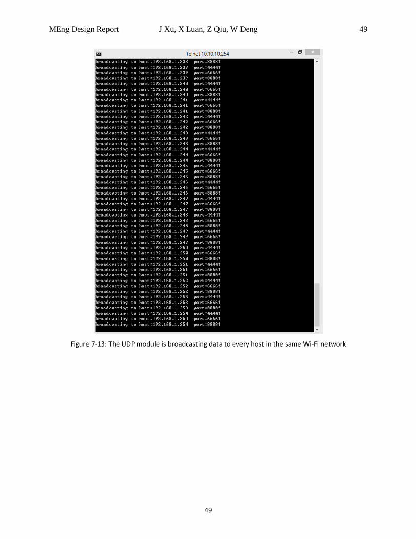
7.3.2 UDP Broadcast
From the WIRESHARK snapshot we can see that the device is try to broadcast. First, the ARP
protocol is applied to find out the host in the same network. When a host is found, it will send
data to it. 192.168.1.164 is the testing computer which also connects to the smartphone
hotspot.
Page 50
MEng Design Report J Xu, X Luan, Z Qiu, W Deng 49
49
Figure 7-13: The UDP module is broadcasting data to every host in the same Wi-Fi network
Page 51
MEng Design Report J Xu, X Luan, Z Qiu, W Deng 50
50
Figure 7-14: The snapshot of WIRESHARK capturing the Wi-Fi network packages.
Another level is the test with the cell phone and the hardware interfaces. This part could be
seen in the test of the whole project.
7.4 Smart Phone Software
To make sure the Android application work as we expect, we created some Linux server test
cases corresponding with the four modes. All the test cases work the same way. We run the
server on a local computer and access the IP address of that computer, then change the
SERVERIP in Android’s code. Take WIFI mode as an example, first of all we let smart phone
connect the same wireless network as server, then run our application. During the testing we
Page 52
MEng Design Report J Xu, X Luan, Z Qiu, W Deng 51
51
output every I/O operation. We pressed the WIFI button, server received the ‘hello:iniWIFI’ and
response with ‘rdy:iniWIFI’. After Android received the ‘rdy’ message, it sent the pre-entered
SSID and password. The server output the SSID and password it got and we check the result.
The message was correct and then we could be sure that the test is successful. We test four
modes and all of them generated the correct result instantaneously, which means that the
Android app can communicate with server without delay.
To test learning mode, we created a server test case that once it receives ‘hello:iniLearn’, it
would send the content store in the local ‘learn.ir’ file. And then smart phone store the data in
database, and we output the content we store in database to check if it’s the same in ‘lean.ir’
Testing control mode is the same as learning mode, we click the control button to see if the
server gets the same content in ‘learn.ir’
Page 53
MEng Design Report J Xu, X Luan, Z Qiu, W Deng 52
52
8 Conclusion
8.1 Summary
In conclusion, we will build a low cost multi-device smart remote control. We will make all
effort to stick to the current time schedule to guarantee the progress of the project. From this
project, we will have a deep knowledge of the Wi-Fi module develop process and good
command of the embedded Linux system design.
For the hardware firmware part we explained how to design infrared transceiver driver on Linux
board. High-resolution timer, interrupt and other technology are used in our driver to
implement high precision delay and avoid system scheduler lock.
For the server part, we built a socket server running on embedded Linux. It is able to build a
stable connection to a Wi-Fi hotspot, then receive or transfer data through the network. To
implement this server, we built a series of useful tools based on the existent network tools. To
make the server stable, we gave the server the ability of testing connection and reconnection.
To enable the smartphone find the server in the network, we build a UDP module to broadcast
the relative information. We also implemented a series of application level protocol on this
server, which are based on TCP protocol.
Our Android application can communicate with the Linux server and the database could store
the learnt data locally and safely. We could query the learnt data in database anytime we want
to control the home electronic devices. There may still exist some situation that may create bug
and ruin the whole process. But our Android app could perform great in most situations as long
as the WIFI connection is good.
8.2 Future Improvement
8.2.1 Bluetooth & ZigBee Module
In the future, we may integrate the Bluetooth 4.0 (BLE) module and ZigBee 2.4GHz RF module
into our current hardware system. These modules will greatly enhance the functionality and
universality of the product as there are many smart devices on the market that supports one of
these two protocols. In addition, these two protocols both support establishing ad-hoc network
mesh, which provides the future possibility of realizing some novel functions like indoor
positioning and cross-platform communication.
8.2.2 Horse-race LED & Breathing Light
In the future, we may also add a horse-race LED module to our system to show some LED
animations and special LED effect. This can indicate different conditions of our device like Wi-Fi
connection, hardware matching process, learning mode waiting, etc. The horse-race LED will
make the product look cooler as well. A breathing light can also be added for the same reason.
Page 54
MEng Design Report J Xu, X Luan, Z Qiu, W Deng 53
53
9 Reference
[1] MediaTek RT5350 SoC Datasheet
http://dlnmh9ip6v2uc.cloudfront.net/datasheets/Wireless/WiFi/RT5350.pdf
[2] TLC555 Timer Datasheet
http://www.fairchildsemi.com/ds/LM/LM555.pdf
[3] ADS1015 ADC Timer Datasheet
http://www.ti.com/lit/ds/symlink/ads1013.pdf
[4] LM35CZ Temperature Sensor Datasheet
http://www.ti.com/lit/ds/symlink/lm35.pdf
[5] PDV-P8103 Photocell Datasheet
http://advancedphotonix.com/wp-content/uploads/PDV-P8103.pdf
[6] 2N2222 Bipolar Transistor Datasheet
http://www.onsemi.com/pub_link/Collateral/P2N2222A-D.PDF
[7] LT1117 Voltage Regulator Datasheet
http://www.linear.com/docs/2946
[8] TSOP 39338 Infrared Receiver Datasheet
http://www.vishay.com/docs/81743/tsop381.pdf
[9] TSAL 7600 IR LED Datasheet
http://media.digikey.com/pdf/Data%20Sheets/Vishay%20Semiconductors/TSAL7600.pdf
[10] C2Q Chip Fuse Datasheet
http://belfuse.com/pdfs/C2Q.pdf
[11] Project: Design your Circuit. Part IV – IR Transmitter
http://dmohankumar.wordpress.com/2012/05/15/design-your-circuit-part-iv-ir-transmitter/
[12] Figure 4-1 and Figure 4-2:
http://blog.csdn.net/wujiangguizhen/article/details/11966167
Page 55
MEng Design Report J Xu, X Luan, Z Qiu, W Deng 54
54
10 Appendix
10.1 Cost and Budget
10.2 Codes
Due to the confidentiality requirement for future commercial use, codes will not be listed in this report.
Part Model Cost Manufacturer
IR Transmitter TSAL7600 0.4 * 6 Vishay Semiconductor
IR Receiver TSOP39338 1 Vishay Semiconductor
Bipolar Transistor 2N2222 0.5*6 Diodes Incorporated
Temperature Sensor LM35CZ 4 Texas Instruments
Photocell PDV-P8103 0.8 Advanced Photonix
C2Q Fuse HCH-1000 0.5 Honeywell
Micro USB Micro USB 2 Molex
ADC ADS1015 4 Texas Instruments
Timer TLC555 1 Texas Instruments
Wi-Fi Module RT5350 8 MediaTek
Regulator LT1117 0.9 Texas Instruments
Total Components Cost 27.6
Total Planned Budget 30