UNCORRECTED PROOF 2 The aluminum–silicon eutectic reaction: mechanisms 3 and crystallography 4 M.M. Makhlouf * , H.V. Guthy 5 Department of Mechanical Engineering, Advanced Casting Research Center, Worcester Polytechnic Institute, WPI, Worcester, MA 01609, USA 6 Abstract 7 The evolution of the contemporary theory for the formation and chemical modification of the aluminum–silicon eutectic is 8 reviewed. The work of Hellawell et al., which laid the foundation for the present day understanding of this technologically important 9 reaction, is critically examined and certain inconsistencies are shown to exist between the contemporary theory and more current 10 concepts. Ó 2002 Published by Elsevier Science Ltd. 11 12 1. Introduction 13 The aluminum–silicon eutectic reaction has been of 14 intense interest ever since Pacz [1] introduced Al–Si al- 15 loys into the United States. In the following years there 16 was an explosion of ideas concerning the mechanism by 17 which this technologically important transformation 18 occurs, and much of our current fundamental under- 19 standing of the reaction may be traced back to the work 20 of Mondolfo [2], and to the more recent sophisticated 21 experimentation of Lu and Hellawell [3,4]. In the present 22 review, the mechanisms and crystallography of the Al–Si 23 eutectic reaction are presented and discussed. After a 24 brief discourse on the equilibrium cooling behavior of 25 Al–Si alloys, the remainder of the review follows an 26 approximately chronological path. Section 3 provides a 27 brief historical perspective of the Al–Si eutectic reaction, 28 and Section 4 deals with the microstructure of the Al–Si 29 eutectic. Sections 5 and 6 review eutectic modification 30 theories circa 1960 and circa 1980, respectively, and 31 Section 7 addresses the more contemporary eutectic 32 modification theories. However, the breakdown of the 33 review is not strictly chronological, because a number of 34 earlier hypothesis have to be discussed in the context of 35 later published literature. No attempt has been made to 36 evaluate the contribution of the eutectic structure to the 37 overall mechanical and physical properties of Al–Si al- 38 loys, and the reader is referred to the relevant literature 39 on that aspect of the reaction (for example [5–14]). 40 Nevertheless, a deliberate attempt has been made to 41 interpret the data available on the evolution of the Al–Si 42 eutectic microstructure within a consistent framework; 43 hence, at times, the review tends to be somewhat sub- 44 jective, and the authors’ biases may be apparent. In 45 order to provide internal self-consistency, some of the 46 illustrations that are cited from the literature have been 47 redrawn and/or adapted. Moreover, illustrations that 48 have not been previously published are included in order 49 to clarify various arguments. Hence, the present article 50 contains a reasonable compendium of findings and data 51 on the evolution of the contemporary understanding of 52 the Al–Si eutectic, as well as a critical review of the 53 current understanding of this important invariant reac- 54 tion. 55 2. The Al–Si phase diagram and equilibrium cooling 56 Muray and McAlister [15] recently reviewed the Al– 57 Si phase diagram. The system is a simple binary eutectic 58 with limited solubility of aluminum in silicon and lim- 59 ited solubility of silicon in aluminum. The solubility of 60 silicon in aluminum reaches a maximum 1.5 at.% at the 61 eutectic temperature, and the solubility of silicon in- 62 creases with temperature to 0.016% Si at 1190 °C. Fig. 1 63 depicts the contemporary Al–Si phase diagram [15]. 64 There is only one invariant reaction in this diagram, 65 namely L ! a þ b ðeutecticÞ ð1Þ 67 In Eq. (1), L is the liquid phase, a is predominantly 68 aluminum, and b is predominantly silicon. It is now Journal of Light Metals xxx (2002) xxx–xxx www.elsevier.com/locate/lightmetals * Corresponding author. E-mail address: [email protected] (M.M. Makhlouf). 1471-5317/02/$ - see front matter Ó 2002 Published by Elsevier Science Ltd. PII:S1471-5317(02)00003-2 LIGMET 22 No. of Pages 20, DTD = 4.3.1 9 March 2002 Disk used SPS-N, Chennai ARTICLE IN PRESS
Transcript
UNCORRECTEDPROOF
2 The aluminum–silicon eutectic reaction: mechanisms3 and crystallography
4 M.M. Makhlouf *, H.V. Guthy
5 Department of Mechanical Engineering, Advanced Casting Research Center, Worcester Polytechnic Institute, WPI, Worcester, MA 01609, USA
6 Abstract
7 The evolution of the contemporary theory for the formation and chemical modification of the aluminum–silicon eutectic is
8 reviewed. The work of Hellawell et al., which laid the foundation for the present day understanding of this technologically important
9 reaction, is critically examined and certain inconsistencies are shown to exist between the contemporary theory and more current
10 concepts. � 2002 Published by Elsevier Science Ltd.11
12 1. Introduction
13 The aluminum–silicon eutectic reaction has been of14 intense interest ever since Pacz [1] introduced Al–Si al-15 loys into the United States. In the following years there16 was an explosion of ideas concerning the mechanism by17 which this technologically important transformation18 occurs, and much of our current fundamental under-19 standing of the reaction may be traced back to the work20 of Mondolfo [2], and to the more recent sophisticated21 experimentation of Lu and Hellawell [3,4]. In the present22 review, the mechanisms and crystallography of the Al–Si23 eutectic reaction are presented and discussed. After a24 brief discourse on the equilibrium cooling behavior of25 Al–Si alloys, the remainder of the review follows an26 approximately chronological path. Section 3 provides a27 brief historical perspective of the Al–Si eutectic reaction,28 and Section 4 deals with the microstructure of the Al–Si29 eutectic. Sections 5 and 6 review eutectic modification30 theories circa 1960 and circa 1980, respectively, and31 Section 7 addresses the more contemporary eutectic32 modification theories. However, the breakdown of the33 review is not strictly chronological, because a number of34 earlier hypothesis have to be discussed in the context of35 later published literature. No attempt has been made to36 evaluate the contribution of the eutectic structure to the37 overall mechanical and physical properties of Al–Si al-38 loys, and the reader is referred to the relevant literature39 on that aspect of the reaction (for example [5–14]).
40Nevertheless, a deliberate attempt has been made to41interpret the data available on the evolution of the Al–Si42eutectic microstructure within a consistent framework;43hence, at times, the review tends to be somewhat sub-44jective, and the authors’ biases may be apparent. In45order to provide internal self-consistency, some of the46illustrations that are cited from the literature have been47redrawn and/or adapted. Moreover, illustrations that48have not been previously published are included in order49to clarify various arguments. Hence, the present article50contains a reasonable compendium of findings and data51on the evolution of the contemporary understanding of52the Al–Si eutectic, as well as a critical review of the53current understanding of this important invariant reac-54tion.
552. The Al–Si phase diagram and equilibrium cooling
56Muray and McAlister [15] recently reviewed the Al–57Si phase diagram. The system is a simple binary eutectic58with limited solubility of aluminum in silicon and lim-59ited solubility of silicon in aluminum. The solubility of60silicon in aluminum reaches a maximum 1.5 at.% at the61eutectic temperature, and the solubility of silicon in-62creases with temperature to 0.016% Si at 1190 �C. Fig. 163depicts the contemporary Al–Si phase diagram [15].64There is only one invariant reaction in this diagram,65namely
L ! a þ b ðeutecticÞ ð1Þ67In Eq. (1), L is the liquid phase, a is predominantly68aluminum, and b is predominantly silicon. It is now
1471-5317/02/$ - see front matter � 2002 Published by Elsevier Science Ltd.PII: S1471-5317 (02 )00003-2
LIGMET 22 No. of Pages 20, DTD=4.3.1
9 March 2002 Disk used SPS-N, ChennaiARTICLE IN PRESS
UNCORRECTEDPROOF
69 widely accepted that the eutectic reaction takes place at70 577 �C and at a silicon level of 12.6%. 1 Fig. 1 shows71 that the Al–Si eutectic can form as follows:
72 1. directly from the liquid in the case of a silicon concen-73 tration of 12.6% (i.e., for a eutectic Al–Si alloy),74 2. in the presence of primary aluminum in the case of
75 silicon contents <12.6% (i.e., for hypoeutectic Al–Si76 alloys), and77 3. in the presence of primary silicon crystals in the case
78 of silicon contents >12.6% (for hypereutectic Al–Si79 alloys).
80 Typical eutectic structures of binary alloys form by81 the simultaneous growth of two phases from the liquid;82 therefore they may exhibit a variety of microstructures83 that can be classified according to two criteria:
84 • lamellar vs. fibrous morphology of the individual85 phases, and86 • regular vs. irregular growth of the individual phases.
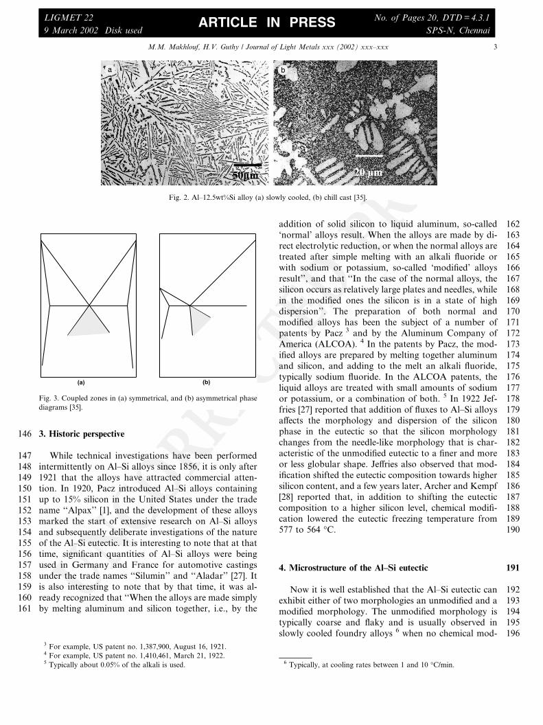
87 Fig. 2 shows the microstructure of the Al–Si eutectic.88 In general, when there are approximately equal volume89 fractions of the two phases, eutectics of binary alloys90 exhibit a lamellar structure. On the other hand, if one91 phase is present in a small volume fraction, this phase92 tends to be fibrous. As a rule of thumb, the eutectic93 microstructure obtained will tend to be fibrous when the94 volume fraction of the minor phase is less than 0.25,95 otherwise it will tend to be lamellar [16]. If both phases96 in the eutectic are non-faceted, the eutectic will exhibit a
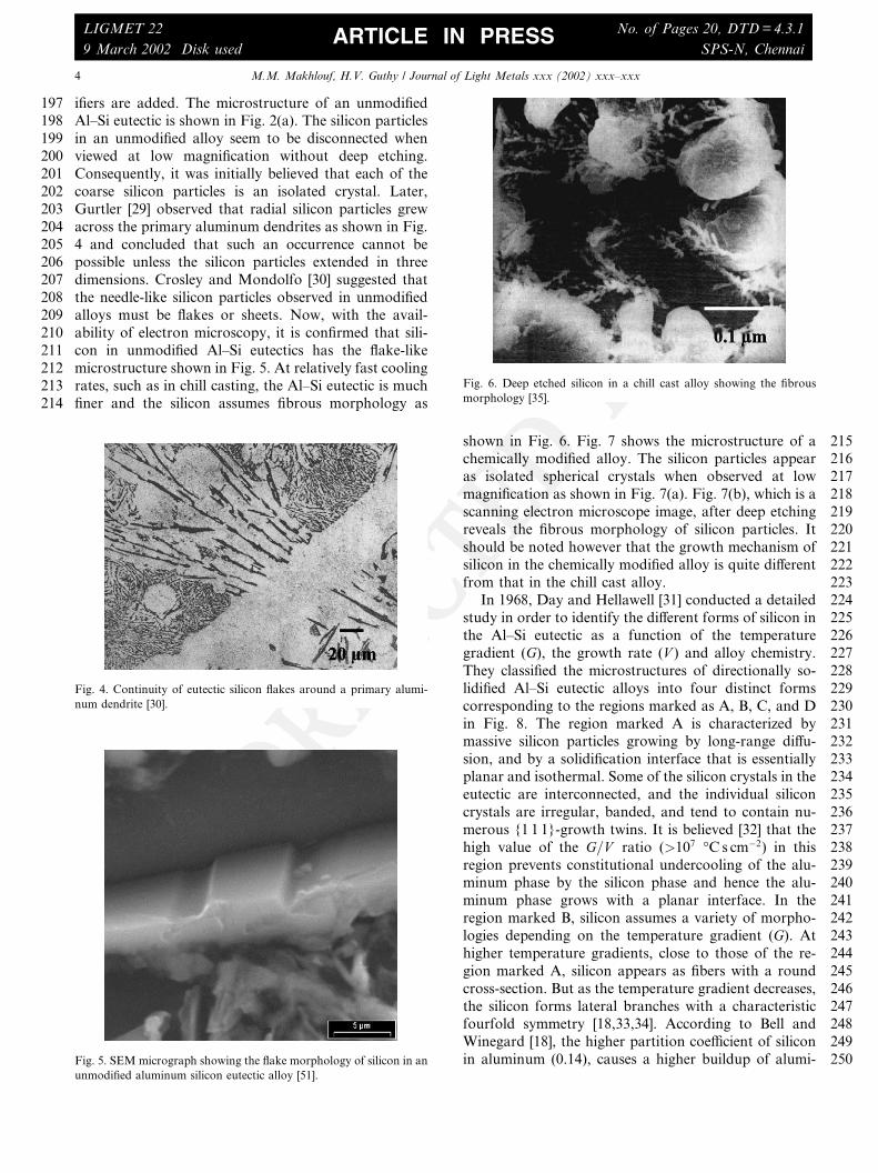
97regular morphology. In this case, the microstructure is98made up of either lamella or fibers having a high degree99of regularity and periodicity. On the other hand, if one100phase is faceted, the eutectic morphology is often ir-101regular. Even though the volume fraction of silicon in102the Al–Si binary is less than 0.25, 2 the typical Al–Si103eutectic is closer to a lamellar structure than to a fibrous104one. This is usually attributed to the strong anisotropy105of growth of silicon and to the relatively low interfacial106energy between silicon and aluminum [16].107It is interesting to note that in 1926, Gwyer and108Phillips [17] determined the composition and tempera-109ture of the eutectic reaction in the Al–Si binary system110to be 11.7% Si and 577 �C respectively. Though the111eutectic temperature is in accord with the currently ac-112cepted value, the eutectic composition was later changed113to 12:2� 0:1 at.% Si [18–20]. The initial error in estab-114lishing the eutectic point is due to the fact that the115temperature of formation of the primary constituents116(aluminum and silicon), as well as the temperature of the117Al–Si eutectic plateau are cooling rate dependent. Pri-118mary silicon undercools more than primary aluminum119hence the eutectic structure forms at 10–12 �C below the120eutectic temperature without appreciable recalescence121[21]. Consequently, at higher cooling rates, the system122behaves as though the eutectic point is shifted to higher123silicon contents and the eutectic temperature is de-124pressed. Fig. 2 illustrates this apparent shift in the eu-125tectic point. Fig. 2(a), which depicts the microstructure126of a eutectic Al–Si alloy that is slowly cooled, shows no127primary aluminum; on the other hand, Fig. 2(b), which128depicts the microstructure of the same alloy cooled at a129relatively faster rate, shows primary aluminum den-130drites.131Depression of the eutectic temperature with increased132cooling rate may be explained on the basis of the cou-133pled region effect [22,23]. Coupled regions represent134fields within the phase diagram where the two phases of135the eutectic are organized in the solid in such a way as to136allow diffusion in the liquid to occur effectively at a137duplex solid/liquid front [19,22,24–26]. Regions of cou-138pled growth are shown schematically in Fig. 3 for both a139symmetric and an asymmetric hypothetical phase dia-140gram. In the Al–Si system, silicon is a non-metal with141directed covalent bonds; therefore, it tends to grow an-142isotropically into faceted crystals and hence it requires143more undercooling for its growth than the isotropic144aluminum phase. Consequently, the coupled region in145the Al–Si system is asymmetric.
Fig. 1. The equilibrium phases diagram for the Al–Si system showing
metastable extensions of the liquidus and the solidus lines [15].
1 Unless otherwise stated, all compositions are in wt%. 2 The volume fraction of silicon in an Al–Si eutectic is 0.143.
9 March 2002 Disk used SPS-N, ChennaiARTICLE IN PRESS
UNCORRECTEDPROOF
146 3. Historic perspective
147 While technical investigations have been performed148 intermittently on Al–Si alloys since 1856, it is only after149 1921 that the alloys have attracted commercial atten-150 tion. In 1920, Pacz introduced Al–Si alloys containing151 up to 15% silicon in the United States under the trade152 name ‘‘Alpax’’ [1], and the development of these alloys153 marked the start of extensive research on Al–Si alloys154 and subsequently deliberate investigations of the nature155 of the Al–Si eutectic. It is interesting to note that at that156 time, significant quantities of Al–Si alloys were being157 used in Germany and France for automotive castings158 under the trade names ‘‘Silumin’’ and ‘‘Aladar’’ [27]. It159 is also interesting to note that by that time, it was al-160 ready recognized that ‘‘When the alloys are made simply161 by melting aluminum and silicon together, i.e., by the
162addition of solid silicon to liquid aluminum, so-called163‘normal’ alloys result. When the alloys are made by di-164rect electrolytic reduction, or when the normal alloys are165treated after simple melting with an alkali fluoride or166with sodium or potassium, so-called ‘modified’ alloys167result’’, and that ‘‘In the case of the normal alloys, the168silicon occurs as relatively large plates and needles, while169in the modified ones the silicon is in a state of high170dispersion’’. The preparation of both normal and171modified alloys has been the subject of a number of172patents by Pacz 3 and by the Aluminum Company of173America (ALCOA). 4 In the patents by Pacz, the mod-174ified alloys are prepared by melting together aluminum175and silicon, and adding to the melt an alkali fluoride,176typically sodium fluoride. In the ALCOA patents, the177liquid alloys are treated with small amounts of sodium178or potassium, or a combination of both. 5 In 1922 Jef-179fries [27] reported that addition of fluxes to Al–Si alloys180affects the morphology and dispersion of the silicon181phase in the eutectic so that the silicon morphology182changes from the needle-like morphology that is char-183acteristic of the unmodified eutectic to a finer and more184or less globular shape. Jeffries also observed that mod-185ification shifted the eutectic composition towards higher186silicon content, and a few years later, Archer and Kempf187[28] reported that, in addition to shifting the eutectic188composition to a higher silicon level, chemical modifi-189cation lowered the eutectic freezing temperature from190577 to 564 �C.
1914. Microstructure of the Al–Si eutectic
192Now it is well established that the Al–Si eutectic can193exhibit either of two morphologies an unmodified and a194modified morphology. The unmodified morphology is195typically coarse and flaky and is usually observed in196slowly cooled foundry alloys 6 when no chemical mod-
3 For example, US patent no. 1,387,900, August 16, 1921.4 For example, US patent no. 1,410,461, March 21, 1922.5 Typically about 0.05% of the alkali is used. 6 Typically, at cooling rates between 1 and 10 �C/min.
9 March 2002 Disk used SPS-N, ChennaiARTICLE IN PRESS
UNCORRECTEDPROOF
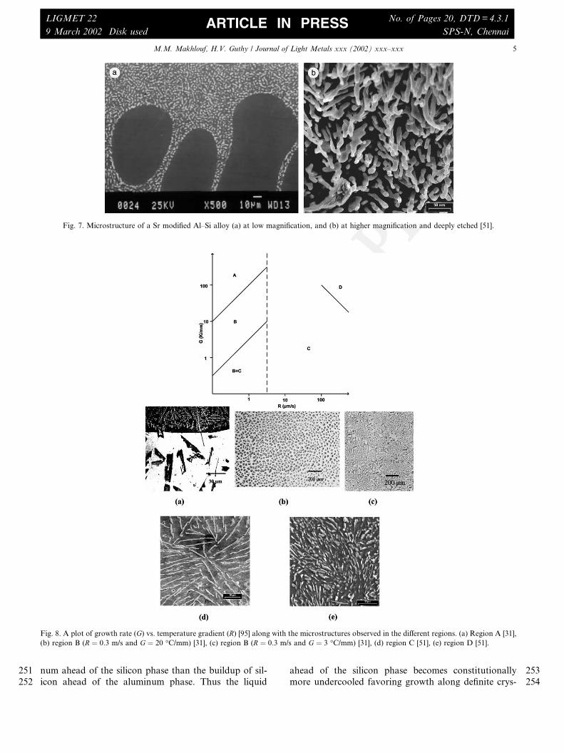
197 ifiers are added. The microstructure of an unmodified198 Al–Si eutectic is shown in Fig. 2(a). The silicon particles199 in an unmodified alloy seem to be disconnected when200 viewed at low magnification without deep etching.201 Consequently, it was initially believed that each of the202 coarse silicon particles is an isolated crystal. Later,203 Gurtler [29] observed that radial silicon particles grew204 across the primary aluminum dendrites as shown in Fig.205 4 and concluded that such an occurrence cannot be206 possible unless the silicon particles extended in three207 dimensions. Crosley and Mondolfo [30] suggested that208 the needle-like silicon particles observed in unmodified209 alloys must be flakes or sheets. Now, with the avail-210 ability of electron microscopy, it is confirmed that sili-211 con in unmodified Al–Si eutectics has the flake-like212 microstructure shown in Fig. 5. At relatively fast cooling213 rates, such as in chill casting, the Al–Si eutectic is much214 finer and the silicon assumes fibrous morphology as
215shown in Fig. 6. Fig. 7 shows the microstructure of a216chemically modified alloy. The silicon particles appear217as isolated spherical crystals when observed at low218magnification as shown in Fig. 7(a). Fig. 7(b), which is a219scanning electron microscope image, after deep etching220reveals the fibrous morphology of silicon particles. It221should be noted however that the growth mechanism of222silicon in the chemically modified alloy is quite different223from that in the chill cast alloy.224In 1968, Day and Hellawell [31] conducted a detailed225study in order to identify the different forms of silicon in226the Al–Si eutectic as a function of the temperature227gradient (G), the growth rate (V ) and alloy chemistry.228They classified the microstructures of directionally so-229lidified Al–Si eutectic alloys into four distinct forms230corresponding to the regions marked as A, B, C, and D231in Fig. 8. The region marked A is characterized by232massive silicon particles growing by long-range diffu-233sion, and by a solidification interface that is essentially234planar and isothermal. Some of the silicon crystals in the235eutectic are interconnected, and the individual silicon236crystals are irregular, banded, and tend to contain nu-237merous {1 1 1}-growth twins. It is believed [32] that the238high value of the G=V ratio (>107 �C s cm�2) in this239region prevents constitutional undercooling of the alu-240minum phase by the silicon phase and hence the alu-241minum phase grows with a planar interface. In the242region marked B, silicon assumes a variety of morpho-243logies depending on the temperature gradient (G). At244higher temperature gradients, close to those of the re-245gion marked A, silicon appears as fibers with a round246cross-section. But as the temperature gradient decreases,247the silicon forms lateral branches with a characteristic248fourfold symmetry [18,33,34]. According to Bell and249Winegard [18], the higher partition coefficient of silicon250in aluminum (0.14), causes a higher buildup of alumi-
Fig. 6. Deep etched silicon in a chill cast alloy showing the fibrous
morphology [35].
Fig. 4. Continuity of eutectic silicon flakes around a primary alumi-
num dendrite [30].
Fig. 5. SEM micrograph showing the flake morphology of silicon in an
9 March 2002 Disk used SPS-N, ChennaiARTICLE IN PRESS
UNCORRECTEDPROOF
251 num ahead of the silicon phase than the buildup of sil-252 icon ahead of the aluminum phase. Thus the liquid
253ahead of the silicon phase becomes constitutionally254more undercooled favoring growth along definite crys-
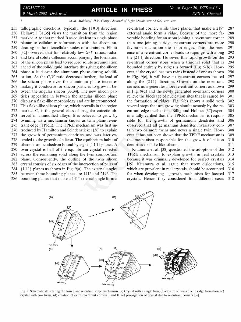
Fig. 7. Microstructure of a Sr modified Al–Si alloy (a) at low magnification, and (b) at higher magnification and deeply etched [51].
Fig. 8. A plot of growth rate (G) vs. temperature gradient (R) [95] along with the microstructures observed in the different regions. (a) Region A [31],(b) region B (R ¼ 0:3 m/s and G ¼ 20 �C/mm) [31], (c) region B (R ¼ 0:3 m/s and G ¼ 3 �C/mm) [31], (d) region C [51], (e) region D [51].
9 March 2002 Disk used SPS-N, ChennaiARTICLE IN PRESS
UNCORRECTEDPROOF
255 tallographic directions, typically, the [1 0 0] direction.256 Hellawell [31,35] views the transition from the region257 marked A to that marked B as equivalent to single phase258 planar to cellular transformation with the silicon nu-259 cleating in the intercellular nodes of aluminum. Elliott260 [32] observed that for relatively low G=V ratios, radial261 and lateral solute diffusion accompanying the formation262 of the silicon phase lead to reduced solute accumulation263 ahead of the solid/liquid interface thus giving the silicon264 phase a lead over the aluminum phase during solidifi-265 cation. As the G=V ratio decreases further, the lead of266 the silicon phase over the aluminum phase increases267 making it conducive for silicon particles to grow in be-268 tween the angular silicon [33,34]. The new silicon par-269 ticles appearing in between the angular silicon phase270 display a flake-like morphology and are interconnected.271 This flake-like silicon phase, which prevails in the region272 marked C, is the general class of irregular eutectic ob-273 served in unmodified alloys. It is believed to grow by274 twinning via a mechanism known as twin plane re-en-275 trant edge (TPRE). The TPRE mechanism was first in-276 troduced by Hamilton and Seindensticker [36] to explain277 the growth of germanium dendrites and was later ex-278 tended to the growth of silicon. The equilibrium habit of279 silicon is an octahedron bound by eight {1 1 1} planes. A280 twin crystal is half of the equilibrium crystal reflected281 across the remaining solid along the twin composition282 plane. Consequently, the outline of the twin silicon283 crystal consists of six edges of the intersection of pairs of284 {1 1 1} planes as shown in Fig. 9(a). The external angles285 between these bounding planes are 141� and 219�. The286 bounding planes that make a 141� external angle form a
287re-entrant corner, while those planes that make a 219�288external angle form a ridge. Because of the more fa-289vorable bonding for an atom joining a re-entrant corner290than one joining a ridge, re-entrant corners are more291favorable nucleation sites than ridges. Thus, the pres-292ence of a re-entrant corner leads to rapid growth along293the [2 1 1] direction. However, this rapid growth on the294re-entrant corner stops when a trigonal solid that is295bounded entirely by ridges is formed (Fig. 9(b)). How-296ever, if the crystal has two twins instead of one as shown297in Fig. 9(c), it will have six re-entrant corners located298along the h211i direction. Growth on the re-entrant299corners now generates more re-entrant corners as shown300in Fig. 9(d) and the newly generated re-entrant corners301relieve the blockage of nucleation sites that is caused by302the formation of ridges. Fig. 9(e) shows a solid with303several steps that are growing simultaneously by the re-304entrant edge mechanism. Billig and Holmes [37] exper-305imentally verified that the TPRE mechanism is respon-306sible for the growth of germanium dendrites and307observed that all germanium dendrites invariably con-308tain two or more twins and never a single twin. How-309ever, it has not been shown that the TPRE mechanism is310the mechanism responsible for the growth of silicon311dendrites or flake-like silicon.312Kitamura et al. [38] questioned the adoption of the313TPRE mechanism to explain growth in real crystals314because it was originally developed for perfect crystals315[39]. Kitamura et al. argue that screw dislocations,316which are prevalent in real crystals, should be accounted317for when developing a growth mechanism for faceted318crystals. Hence, they considered four different cases
Fig. 9. Schematic illustrating the twin plane re-entrant edge mechanism. (a) Crystal with a single twin, (b) closure of twins due to ridge formation, (c)
crystal with two twins, (d) creation of extra re-entrant corners I and II, (e) propagation of crystal due to re-entrant corners [36].
9 March 2002 Disk used SPS-N, ChennaiARTICLE IN PRESS
UNCORRECTEDPROOF
319 based on the presence or absence of screw dislocations320 and twin junctions on the surface of a crystal. As shown321 in Fig. 10, there are basically four preferential growth322 sites in a given faceted crystal. Listed in decreasing order323 of their effectiveness, these are kinks, steps, re-entrant324 corners and surface nucleation sites. 7 In the case de-325 picted in Fig. 10(a) there is no screw dislocations ex-326 posed on the surface, neither at the twin junction nor at327 the crystal surface. Hence the operative growth mecha-328 nism in this case is the TPRE mechanism. In the case329 depicted in Fig. 10(b) a screw dislocation is exposed at a330 twin junction; hence, preferential growth occurs at the331 twin junction. In this case there is growth on both sides332 of the crystal, i.e., the crystal grows in both forward and333 backward directions. In the case depicted in Fig. 10(c) a334 screw dislocation is exposed on the surface of the crys-335 tal. As screw dislocations initiate easy surface nucle-336 ation, growth occurs uniformly on all the crystals337 surfaces, and the TPRE mechanism does not contribute338 to growth. In the case depicted by Fig. 10(d) screw339 dislocations are exposed at both a twin junction and the340 crystal surface. In this case, growth of the crystal de-341 pends on the density of screw dislocations on the surface342 and at the twin junction. If the density of screw dislo-343 cations at the twin junction is higher than that at the344 crystal surface, growth will occur preferentially along
345the twin junction, and the resulting crystal will resemble346those that grow by the TPRE mechanism. Sunagawa347and Yasuda [40] proved by means of X-ray topography348that growth in quartz crystals occurs at the re-entrant349corner of a twin junction due to the concentration of350screw dislocations. Extension of Sunagawa’s [40] hy-351pothesis to eutectic flake-like silicon crystals would in-352variably cast doubt that the TPRE is the operating353mechanism in these crystals.
3545. Eutectic modification theories circa 1960
355Theories that explain the effect of specific chemical356additives on the morphology of the eutectic Al–Si357structure were proposed as early as 1911 when Frilley358[41] described the modified structure of an Al–Si alloy359that was produced by direct electrolytic reduction of360aluminum oxide and silicon dioxide. For example, in3611922 Guillet [42] and also Search [43] proposed that the362change in the Al–Si eutectic structure with addition of363sodium fluoride and potassium fluoride was due to the364removal of oxides and impurities, such as alumina and365silica, by the fluxing effect of these compounds. How-366ever, Curran [44] reasoned that since modification of the367Al–Si eutectic was also possible with metallic sodium,368fluxing of impurities does not play a role in modifica-369tion. Instead, he proposed that modification was due to370the formation of an Al–Si–sodium ternary alloy [45].371The modified silicon morphology was supposedly the372regular morphology of this ternary eutectic. Curran also373observed that when Al–Si alloys are held for a long374period of time after flux addition, the modification effect375disappears. He explained this ‘‘fading’’ effect of the376modified structure as being caused by the vaporization377of sodium from the melt [44]. In 1924, Edwards and
Fig. 10. Hypothetical alignments of a screw dislocation and a re-entrant corner [38].
7 Note that the effectiveness of re-entrant corners as growth sites is
dependant upon the magnitude of the re-entrant angle. Small re-
entrant angles are more effective than large ones. However, small re-
entrant angles limit mass transfer towards the re-entrant corner. Thus
a balance between these two characteristics determines the effectiveness
of re-entrant corners as growth sites, and at times the effectiveness of
re-entrant corners may exceed that of steps. It should also be noted
that if undercooling is excessive, surface nucleation could dominate the
growth mechanism. Hence the order mentioned above is valid only for
9 March 2002 Disk used SPS-N, ChennaiARTICLE IN PRESS
UNCORRECTEDPROOF
378 Archer [46] systematically studied cooling curves of379 hypoeutectic and hypereutectic Al–Si alloys and found380 that the eutectic freezing temperature was lowered from381 its equilibrium value while the melting point remained at382 the equilibrium eutectic temperature of 577 �C. This383 observation led them to rule out the possibility that an384 Al–Si–sodium ternary alloy is responsible for modifica-385 tion because in a ternary system the melting and freezing386 points coincide. Edwards and Archer [46] also tested the387 hypothesis that eutectic modification is caused by a388 change in the allotropic form of silicon by performing389 X-ray spectrography on modified and unmodified alloy390 powders. In both cases the alloys showed identical pat-391 terns of silicon imposed on patterns of aluminum, thus392 eliminating different allotropic forms of silicon in un-393 modified and modified alloys as a cause of eutectic394 modification. Earnestly searching for a theory that can395 explain chemical eutectic modification, Edwards and396 Archer [46], and also later Gwyer and Phillips [17],397 proposed a theory that became known as the dispersed398 colloidal phase theory. According to this theory, solid-399 ification of Al–Si alloys occurs when the aluminum and400 silicon atoms gradually pass from a state of atomic401 dispersion in the liquid phase to a crystalline form402 characteristic of the solid phase. During this change,403 small colloidal silicon particles (presumably 10�9–10�11
404 m in diameter) form and coagulate into silicon crystals.405 When sodium is present in the alloy, and since sodium406 has little solubility in solid aluminum, the rejected so-407 dium atoms deposit onto these colloidal silicon particles408 and form a protective coating. Once formed, this pro-409 tective coating hinders further crystallization of silicon410 and retards the growth of silicon particles thus modi-411 fying the silicon morphology and depressing the eutectic412 temperature. Hume Rothery [21] disagreed with the413 dispersed colloidal phase theory and reasoned that col-
414loids imply the existence of an electric charge on the415dispersed phase, which is improbable in the case of an416Al–Si alloy because of the high electrical conductivity of417aluminum. Instead, he proposed that as liquid metal418approaches the solid state, atoms group together and419form complexes that eventually become nuclei. Addition420of modifiers destroys these complexes and thus causes421the observed change in the morphology of the silicon422phase. Fifty years later, Bian et al. [47] used high tem-423perature X-ray diffraction and verified this phenome-424non. 8 In 1957, Plumb and Lewis [48] used a mixture of425HCl and HNO3 to dissolve the aluminum phase in426hypoeutectic Al–Si alloys that were modified with427varying levels of irradiated sodium. They then used428autoradiography to analyze for sodium in the dissolved429aluminum and in the silicon. A plot of sodium content in430the aluminum phase and in the silicon phase vs. the431initial sodium content of the alloy (Fig. 11) shows that432sodium resides preferentially with aluminum, which433further disproves the dispersed colloidal phase theory.434In 1949, Thall and Chalmers [49] proposed a mech-435anism that attempted to explain chemical modification436of the Al–Si eutectic based on the surface energy of the437aluminum/silicon solid interface. They suggested that438the rate of advance of the interface depends on a balance439between the rate of heat flow from the liquid to the solid440through the interface and the latent heat of fusion re-441leased during solidification. The thermal conductivities442of aluminum and silicon in their pure form are 0.53 and4430.20 cal/cm2/�C respectively, and their latent heats of444fusion are 94.6 and 337 cal/g respectively. Since the445difference between the magnitude of the thermal con-
Fig. 11. Sodium analysis in the silicon and in the aluminum constituents of an Al–7.5%Si alloy as a function of sodium concentration [48].
8 See Section 7 for a description of Bian et al.’s experiments and
9 March 2002 Disk used SPS-N, ChennaiARTICLE IN PRESS
UNCORRECTEDPROOF
446 ductivity of pure aluminum and pure silicon and the447 difference between the magnitude of the latent heat of448 fusion of pure aluminum and pure silicon are large,449 aluminum will solidify much faster than silicon. Thus,450 aluminum gains a lead during solidification of the eu-451 tectic as shown in Fig. 12(a). As the cooling rate in-452 creases, the lead of aluminum over silicon increases and453 causes complete encasement of the lagging silicon crystal454 by the advancing aluminum as illustrated in Fig. 12(b)455 and (c). This theory accounts for the formation of the456 modified eutectic structure at high cooling rates. For457 chemical modification, the authors suggest that a de-458 crease in surface energy of the Al–Si solid interface upon459 the addition of the chemical modifier increases the in-460 terface angle h as shown in Fig. 13. This in turn sup-461 presses growth of the silicon crystal and causes462 modification of the eutectic structure as well as signifi-463 cant undercooling. Despite the elegance of this theory, it464 was later shown that silicon, not aluminum, is the465 leading phase at the Al–Si solid interface [50]. Fig. 14466 shows micrographs of electro-polished strontium mod-467 ified and unmodified high purity Al–7%Si alloys that468 clearly illustrate this fact [51].469 Tsumara [52] observed that the solubility of sodium470 in solid aluminum and in solid silicon is low, and hence471 sodium segregates ahead of the growing interface and472 restricts the diffusion of silicon in the melt. Tsumara473 reasoned that this reduced silicon diffusion is responsible474 for the observed change in its growth morphology upon475 modification with sodium. Diffusion couple experiments476 conducted later by Davies and West [53] confirmed that
477sodium reduces the diffusion rate of silicon in molten478aluminum. However, Davies and West reported also479that when an unmodified eutectic alloy is solidified in a480steep temperature gradient at a very low cooling rate in481an atmosphere of sodium vapor, a completely modified482sample is obtained, which strongly suggests that the483reduced diffusion rate of silicon in molten Al–Si alloys is484not responsible for chemical modification of the Al–Si485eutectic.486Therefore, by the late 1950s, it appeared to be well487established that
488• The modified silicon morphology is obtainable either489by the use of chemical additives such as sodium, or by490fast cooling, and491• Addition of sodium to Al–Si alloys shifts the Al–Si492eutectic composition towards higher silicon values,493and also suppresses the eutectic growth temperature,494but the melting point of the eutectic alloy remains un-495changed.
496Yet, no unifying theory of the Al–Si eutectic reaction,497or indeed its kinetics, emerged. In the 1960s and through498the 1970s, efforts continued in order to develop a sound499understanding of the reaction, and to rationalize the500hitherto well-established facts into a consistent theory501that describes the formation of the Al–Si eutectic and502the modification of its morphology by specific chemical503additives. Section 6 reviews the most noticeable efforts504of this period.
9 March 2002 Disk used SPS-N, ChennaiARTICLE IN PRESS
UNCORRECTEDPROOF
505 6. Eutectic modification theories circa 1980
506 In the early 1960s, Davies and West [25] considered507 the possibility that sodium reduced the growth rate of508 eutectic silicon by a process that involved interfacial509 poisoning of the growth sites of silicon. In their inves-510 tigation, they analyzed the growth rates of silicon when511 unmodified Al–Si eutectic alloys were placed on top of a512 pure polycrystalline silicon substrate with and without513 an atmosphere of sodium. They observed that the
514growth of silicon in the presence of sodium was negli-515gible compared to its growth in the absence of sodium as516shown in Fig. 15. Moreover, they observed that silicon517tended to be faceted when sodium was present in the518atmosphere. Based on these two observations, Davies519and West concluded that sodium atoms poisoned the520growth sites of silicon. However, Davies and West did521not find a significant difference between the magnitudes522of the substrate/melt dihedral angle in melts that were523equilibrated for a long time in the presence of sodium
Fig. 15. Growth of silicon from the eutectic on a silicon substrate. (a) Grain boundary between eutectic and silicon without sodium, (b) growth of
twins from the substrate into the eutectic silicon in the absence of sodium, (c) and (d) growth of silicon in the presence of sodium [53].
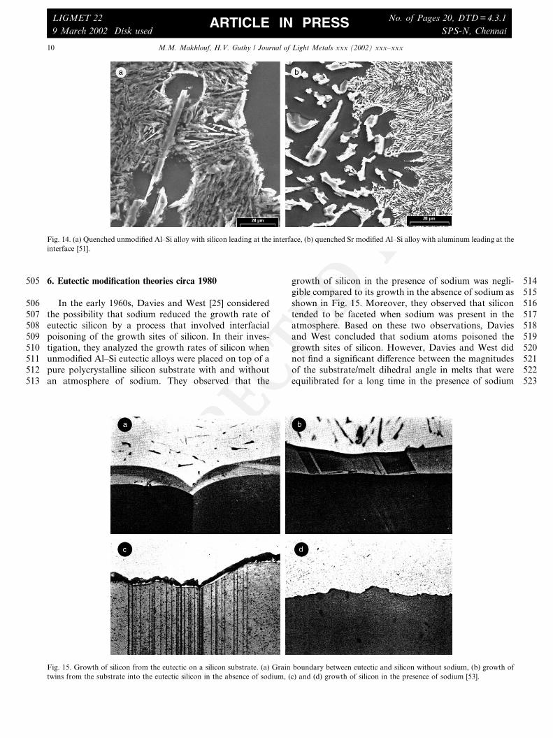
Fig. 14. (a) Quenched unmodified Al–Si alloy with silicon leading at the interface, (b) quenched Sr modified Al–Si alloy with aluminum leading at the
9 March 2002 Disk used SPS-N, ChennaiARTICLE IN PRESS
UNCORRECTEDPROOF
524 and similar melts that were equilibrated in its absence.525 Although sodium did reduce the surface energy, its in-526 ability to change the dihedral angle was considered527 sufficient grounds to discount surface energy changes528 due to sodium addition as the mechanism behind529 chemical modification. However, given the important530 role that surface energy plays in nucleation and growth531 of silicon, the significant reduction in surface energy532 observed by Davies and West and depicted in Fig. 16533 cannot be overlooked. Moreover, recent sessile drop534 experiments by Guthy and Makhlouf [51] show that the535 prolonged melt equilibration times used by Davies and536 West [25] may have resulted in substantial loss of so-537 dium from the melt prior to dihedral angle measure-538 ments. Guthy and Makhlouf [51] found that sodium539 modified Al–Si eutectic sessile droplets take longer than540 unmodified droplets to wet an Al–1%Si substrate.541 However, after a long equilibration time, both unmod-542 ified and modified droplets completely wet the surface543 proving that the change in surface energies caused by544 modification is dynamic and is lost after equilibration.545 Also in the early 1960s, Kim and Heine [54] con-546 ducted quench experiments and thermal analysis of547 various hypoeutectic, eutectic and hypereutectic Al–Si548 alloys and observed that flake silicon, which is charac-549 teristic of the unmodified eutectic is obtained at high550 temperature, while fibrous silicon, which is characteristic551 of the modified eutectic is obtained at the relatively552 lower temperature associated with substantial underco-553 oling. Kim and Heine proposed that the morphology of554 silicon in the Al–Si eutectic is dependent on the tem-555 perature at which it grows and this became commonly556 known as the ‘‘growth-temperature/phase-shape’’ hy-557 pothesis. The growth-temperature/phase-shape hypoth-558 esis has its origins in studies performed earlier by Mason
559[55,56] who experimentally proved that ice crystals could560be made to grow from water in various shapes de-561pending on the temperature at which they are grown.562However, it seems unreasonable to draw an analogy563between the growth of ice, which is essentially a chem-564ical compound and the growth of silicon, which is a565semi-metal, particularly when the growing silicon crys-566tals are within an aluminum matrix. Regardless, Gigill-567ioti and Colligan [57] later disproved the validity of the568growth-temperature/phase-shape hypothesis for ex-569plaining modification of the Al–Si eutectic by carefully570examining the morphology of silicon at different growth571temperatures and noting that the eutectic silicon mor-572phology does not change with growth temperature as573proposed by Kim and Heine. Kim and Heine [54] also574studied the growth mode of modified and unmodified575eutectic Al–Si alloys and found a critical difference be-576tween the two. The eutectic in modified alloys tends to577grow from the surface of a casting towards the center,578while that in unmodified alloys tends to grow randomly579within the melt as shown in Fig. 17. Kim and Heine580attributed this phenomenon to the suppression of silicon581nucleation in the modified alloys. However, recently,
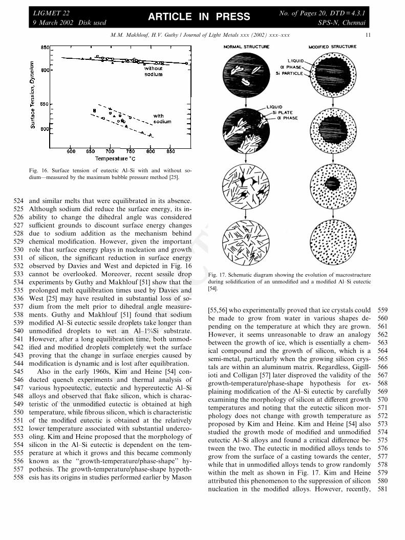
Fig. 16. Surface tension of eutectic Al–Si with and without so-
dium––measured by the maximum bubble pressure method [25].
Fig. 17. Schematic diagram showing the evolution of macrostructure
during solidification of an unmodified and a modified Al–Si eutectic
9 March 2002 Disk used SPS-N, ChennaiARTICLE IN PRESS
UNCORRECTEDPROOF
582 Dahle and Arnberg [58], conducted similar experiments583 and their results seem to contradict those of Kim and584 Heine. 9
585 In the early to mid-1960s, Crosley and Mondolfo586 conducted extensive investigations aimed at under-587 standing the formation of the eutectic structure in var-588 ious alloy systems [2,59–61] and concluded that
589 • heterogeneous nucleation of the eutectic is mainly590 controlled by the surface energies, and591 • nucleation between the two eutectic phases works
592 only one way, i.e., if the a phase nucleated the b593 phase, then the b phase becomes incapable of nucle-594 ating the a phase.
595 Moreover, Crosley and Mondolfo conducted unique596 experiments [2] aimed at investigating the nucleation597 ability of aluminum phosphide in the presence and ab-598 sence of sodium. Their findings are best explained with599 the help of Fig. 18. Aluminum phosphide particles act as600 good nucleating agents both for primary silicon and for601 eutectic silicon. During solidification of hypoeutectic602 Al–Si alloys, the undercooling required for nucleation of603 eutectic silicon by the a phase (line 5 in Fig. 18) is more604 than the undercooling required for eutectic silicon to605 nucleate on AlP particles (line 2 in Fig. 18). Thus the606 eutectic silicon nucleates on AlP first and then as the607 temperature reaches point H, eutectic silicon nucleates608 on primary aluminum. The presence of sodium poisons609 the nucleating capacity of AlP particles, probably by610 forming sodium phosphide, consequently, when sodium
611is present, silicon nucleates on primary aluminum only.612Bercovici [62] confirmed Crosley and Mondolfo’s find-613ings and proved that the amount of sodium (or Sr) that614is required for modification increases with the amount of615phosphorous in the alloy.616It is important at this point to mention that although617it is widely believed that Crosley and Mondolfo sug-618gested that nucleation plays a dominant role in the619modification of the Al–Si eutectic, they do contend that620modification is due only to a change in the eutectic621growth conditions [30]. Crosley and Mondolfo cate-622gorically state that silicon leads the solid/liquid interface623during the solidification of unmodified alloys and alu-624minum leads during the solidification of modified alloys625[30] and attribute this change in lead to a change in the626surface tension of liquid aluminum, and a reduction in627the rate of Si diffusion in the liquid when sodium is628present. Moreover, Crosley and Mondolfo contend that629silicon re-nucleates after being completely encased by630aluminum in modified alloys. However, it was later631found that silicon in both unmodified and modified al-632loys is continuous, which obviates the need for re-nu-633cleation [31,63,64].634In the early 1970s, Fredriksson et al. [65] studied the635growth mechanism of primary silicon in modified Al–Si636alloys using directional solidification experiments. They637observed that the TPRE mechanism is not operative in638primary silicon and concluded that nucleation of new639atomic planes on {1 1 1} primary silicon facets are easier640than growth by the TPRE mechanism. Upon addition of641sodium, primary silicon develops {1 0 0} facets and at642very high sodium levels, primary silicon approaches a643more or less spherical shape. They also concluded that644addition of sodium changes the growth mechanism to a645step-wise mode due to the formation of a new thin layer646of silicon at preferred sites and the lateral spreading of647this layer over the crystal’s face. Fredriksson et al. at-648tribute this change from surface nucleation to step-wise649nucleation to immobilization of the silicon crystal’s fa-650ces by adsorption of sodium on its facets.651It is worth noting that, until the early 1970s, sodium652was the universally accepted chemical modifier of the653Al–Si eutectic, mainly because of its low cost and its654uniform and fast dissolution in Al–Si melts. However,655the difficulty in controlling its concentration in molten656alloys and the excessive fuming that resulted during its657addition to the melt presented major problems that fu-658eled the search for its replacement. Eventually, alumi-659num–strontium master alloys were designed [66,67] and660gradually replaced sodium as the chemical modifier of661choice.662In the mid 1970s, Jenkinson and Hogan [68] con-663ducted directional solidification studies aimed at un-664derstanding modification of Al–Si alloys with strontium665in a manner similar to that developed by Day and666Hellawell [31]. In addition to determining the coupled
9 The experiments and results of Dahle and Arnberg are reviewed in
Section 7.
Fig. 18. The Al–Si phase diagram with nucleation lines: (1) nucleation
of aluminum by an unknown impurity, (2) nucleation of silicon by
AlP, (3) nucleation of silicon by AlNaSi, (4) nucleation of silicon by an
unknown impurity, (5) nucleation of silicon by aluminum, (6) nucle-
ation of silicon by aluminum in the presence of sodium [30].
9 March 2002 Disk used SPS-N, ChennaiARTICLE IN PRESS
UNCORRECTEDPROOF
667 zone for modification with strontium, Jenkinson and668 Hogan conducted transmission electron microscopy669 (TEM) studies on extraction replicas of silicon fibers670 obtained by strontium modification as shown in Fig.671 19(a). They observed multiple twinning on {1 1 1} planes672 with the silicon fibers oriented along the h100i direction,673 which highlights the role of twins in the growth of fi-674 brous silicon. However, it is important to note that while675 silicon fibers obtained by impurity modification contain676 significant numbers of twins, silicon fibers obtained by677 quench modification do not as evidenced in Fig. 19(b)678 [69,70].679 Jenkinson and Hogan [68] also examined the micro-680 structure of anodized surfaces of modified and unmod-681 ified Al–Si specimens under polarized light in order to682 observe the grain morphology of the a phase. Fig. 20 is683 from Jenkinson and Hogan [68] and shows that the684 unmodified a grains structure is much finer than their685 modified counterparts. Moreover, the a grains in the686 unmodified alloy are equiaxed in both longitudinal and687 transverse sections, while in the modified alloy they are688 not equiaxed but are elongated in the growth direction.689 This observation indirectly confirms that, in unmodified690 Al–Si eutectics, silicon is the leading phase and forces691 aluminum to nucleate between the silicon plates forming692 equiaxed grains as shown in Fig. 21 [51,71]. On the other693 hand, in modified Al–Si eutectics, modifier atoms poison694 the re-entrant twin grooves and reduce the rate of silicon695 atom attachment [72]. However, unlike previous inves-696 tigators, e.g., [2], Jenkinson and Hogan believe that the697 aluminum growth in modified alloys eventually catches698 up with the slowly growing silicon and form a coupled699 growth front that gives rise to the characteristic fibrous700 morphology.701 Despite these and many other efforts (e.g., [18,73,74])702 during the 1960s and 1970s, a unifying theory for the
703formation of the Al–Si eutectic and the modification of704its morphology by chemical additives remained elusive.705However, fueled by the ever-increasing pervasiveness of706Al–Si alloys, the 1980s and 1990s witnessed considerable
Fig. 19. (a) TEM micrograph of an extraction replica of strontium modified eutectic silicon showing multiple {1 1 1} twins [68]. (b) TEM micrograph
of a quench modified silicon fiber [3].
Fig. 20. (a) Longitudinal section of an unmodified Al–Si alloy showing
a fine-grained aluminum matrix solidified at a growth rate of 12 lm/sand a temperature gradient of 90 �C/cm [68].
9 March 2002 Disk used SPS-N, ChennaiARTICLE IN PRESS
UNCORRECTEDPROOF
707 efforts dedicated to deciphering the nature of the Al–Si708 eutectic and the kinetics of its chemical modification.709 Today, two schools of thought exist each with its dis-710 tinct ideas regarding the genesis of the Al–Si eutectic711 and the modification of its morphology via chemical712 additives. One school believes that the mechanism un-713 derlying the nucleation of eutectic silicon in Al–Si alloys714 eventually determines the eutectic silicon morphology;715 the other attributes the morphology of the silicon eu-716 tectic to the kinetics of its growth. The views and efforts717 of both schools, together with arguments that have been718 put forth in their support, are presented in Section 7.719 Particular attention is given to the work of Lu and720 Hellawell [3] since it is considered by many to be the721 basis for the contemporary Al–Si eutectic modification722 theory.
724 Understanding the evolution of the morphology of725 primary silicon and the role that chemical additives play726 in influencing this morphology is constructive in un-727 derstanding the genesis and modification of the Al–Si728 eutectic. Consequently, prior to presenting relevant729 contemporary efforts that aim at explaining the forma-730 tion and modification of the Al–Si eutectic, efforts that731 relate to the nucleation and growth kinetics of primary732 silicon in Al–Si alloys are presented.
7337.1. Nucleation and growth characteristics of primary734silicon in Al–Si alloys
735In 1959, Bernal [75] suggested that when close to their736freezing point, atoms arrange themselves in the form of737tetrahedrons and he speculated that nucleation of solid738silicon in a melt occurs on embryos that form by the739coalescence of these tetrahedrons. Bernal also suggested740that the optimum shape of these embryos is dictated by741surface energy considerations and an embryo bound by742low energy facets of {1 1 1} planes is the most thermo-743dynamically stable. Calculations of the surface energy of744various polyhedrons that can form from tetrahedrons745[76] show that a decahedron formed from five tetrahe-746drons in a twin relationship has the least surface energy.747Hence, the most stable silicon nucleus is a decahedron748bound by {1 1 1} facets. Once formed, this nucleus749grows at locations with multiple twins by the TPRE750mechanism. Thus, according to Bernal, primary silicon751nucleates on equiaxed, twinned embryos and grows into752different morphologies. The most commonly observed753primary silicon morphologies are massive primary sili-754con, which is also known as polygonal silicon, and star-755like primary silicon.756In 1979, Kobayashi and Hogan [77] proposed a757mechanism for the formation of star-like primary silicon758in aluminum alloys based on previous studies [78–80]759that Kobayashi et al. conducted on FCC metals where760they showed that multiply twinned, equiaxed particles of761the same metal that have low energy {1 1 1} surface762facets act as heterogeneous nuclei during solidification.763Kobayashi and Hogan argued that since silicon has a764diamond cubic structure, which is similar to the FCC765structure, similar nucleation sites could be active during766its solidification.767Polygonal primary silicon crystals also are bound by768{1 1 1} planes, [70] and are typically twinned as shown in769Fig. 22. However, careful consideration of the geometry770of these crystals shows that they cannot grow by twin-771ning. Instead, at high growth velocities, the edges and772corners of the crystals become preferred growth sites773and a dendrite-like silicon phase such as that shown in774Fig. 23 forms. At slow cooling rates, on the other hand,775the TPRE growth mechanism becomes predominant776and the crystals assume a plate-like morphology with777closely spaced twin planes aligned parallel to their778longer axis as shown in Fig. 24. It is interesting to note779however, that in the presence of sodium, most of the780star-like primary silicon particles disappear and are re-781placed by spherical silicon particles. 10 Therefore it may782be inferred that chemical modifiers disable the TPRE
Fig. 21. Eutectic aluminum grains nucleating on silicon flakes in an Al–
7%Si alloy quenched at 10% of the eutectic plateau [51].
10 The silicon particles are not exactly spherical as micro facets
similar to the fibrous eutectic typical of chemically modified Al–Si
9 March 2002 Disk used SPS-N, ChennaiARTICLE IN PRESS
UNCORRECTEDPROOF
783mechanism and preserve the equiaxed shape. However,784the exact mechanism by which this occurs is not well785understood.
7867.2. Growth characteristics of the Al–Si eutectic
7877.2.1. Growth characteristics of the unmodified Al–Si788eutectic789Kobayashi and Hogan [81] suggested that nucleation790of flat plate silicon (flake silicon) occurs when two791groups, each made up of a few silicon atoms arranged in792a tetrahedron, combine together as illustrated schemat-793ically in Fig. 25(a) to form an embryo. Once formed, the794embryo develops into a critical size nucleus by the at-795tachment of single silicon atoms to its surfaces. In this796arrangement, the central mirror plane between the two797tetrahedrons becomes a {1 1 1} twin plane. More tetra-798hedrons can add to the growing nucleus, which mini-799mizes its surface energy by forming {1 1 1} planes at its800corners as shown in Fig. 25(b). The presence of two or801more {1 1 1} twin planes triggers growth of the silicon802phase via the TPRE mechanism, resulting in a plate-like803morphology. Plate-like silicon can change its growth804direction depending on the solidification conditions by805displacement twinning or by multiple twinning [82].806Displacement twinning, which predominates at lower807growth velocities, occurs by growth of twins lateral to808the main flake as shown in Fig. 26. Repeated side809branching causes the flake to grow at any arbitrary810angle to the main flake. Multiple twinning, on the other811hand, is observed only at relatively high growth veloci-812ties, and the angle of direction change is an integer813multiple of 70.5� in order to conform to the twinning814angle as shown in Fig. 27. Branching caused by multiple815twinning occurs mostly because it increases the inter-816flake spacing and thus the silicon needed for further817growth at each flake tip becomes readily available.
Fig. 22. Primary silicon crystal with multiple twin planes [70].
Fig. 23. Dendritic primary silicon in an Al–17%Si [70].
Fig. 24. Primary silicon in the form of plates in an Al–20%Si alloy [70].
9 March 2002 Disk used SPS-N, ChennaiARTICLE IN PRESS
UNCORRECTEDPROOF
818 Kobayashi et al. [83] and later Shamsuzzoha and819 Hogan [84] determined the orientation relationships820 between eutectic aluminum and eutectic silicon in un-821 modified Al–Si alloys. They observed the following re-822 lations at lower growth velocities, i.e., about 100 lm/s
824 On the other hand, at higher growth velocities; i.e.,825 about 750 lm/s, the most frequently observed relation-826 ship was ½001�Alk½110�Si : ð100ÞAlk½�111�11�Si. The common827 feature of these relationships is that ð102ÞAl lies parallel828 to the {1 1 1} twin plane of silicon. This is worth noting829 since this orientation minimizes the difference in inter-
830planar spacing at the interface between aluminum and831silicon.
8327.2.2. Growth characteristics of the modified Al–Si833eutectic834Lu and Hellawell [69] and also Shamsuzzoha and835Hogan [85] conducted detailed TEM studies on impurity836modified silicon fibers in order to document their growth837mechanism. Fig. 28 shows twin traces of a modified fi-838ber. Fig. 28(a) and (b) are bright field TEM images, and839Fig. 28(c) and (d) are the dark field images of the same840silicon fiber. The growth of silicon is in a zigzag fashion841similar to the branching scheme observed in the flake842silicon and shown in Figs. 26 and 27. Electron diffrac-
Fig. 26. Schematic representation of growth of flake silicon by displacement twinning [84].
Fig. 27. Schematic representation of growth of flake silicon by multiple twinning [84].
9 March 2002 Disk used SPS-N, ChennaiARTICLE IN PRESS
UNCORRECTEDPROOF
843 tion patterns obtained from the fibers reveal the growth844 mechanism illustrated schematically in Fig. 28(e). The845 twins marked AB in the left bottom of Fig. 28(e) give846 rise to branches in the form of twins BC by multiple847 twinning. Further growth is possible by nucleation of848 more AB twins on the surface marked C. This process of849 multiple twinning repeats itself and generates the entire850 fiber. The growth direction of the AB twins is [1 1 2] and851 the growth direction of the BC twins is [1 1 2]. Lu and852 Hellawell [69] observed significant twinning in the flake853 morphology and the impurity modified fibers, but not in854 the quench modified fibers. Moreover, they observed855 that twinning in the impurity modified fibers was more856 frequent than in the silicon fiber with flake morphology.857 Based on these observations they concluded that silicon858 in the flake morphology grows predominantly by the859 layer mechanism illustrated in Fig. 29 and not by the860 TPRE mechanism.861 In 1987, Lu and Hellawell [3] introduced the impurity862 induced twinning theory in order to explain the mech-863 anism by which chemical modifiers such as sodium and
864strontium affect the morphology of eutectic silicon, and865soon after, this became the more widely accepted eu-866tectic modification theory. According to the impurity867induced twinning theory, chemical modifiers are impu-868rities that poison already growing atomic silicon layers869by becoming adsorbed onto surface steps and kinks thus870preventing the attachment of silicon atoms to the crys-871tal. Furthermore, the adsorbed impurity atoms induce872twinning by altering the stacking sequence of atomic873layers as the newly added layers seek to grow around the874adsorbed impurity atom. Lu and Hellawell assumed a875face centered cubic structure and calculated the ratio of876impurity atom radius ðriÞ to matrix atom radius ðrÞ that877is required for impurity induced twinning and found it878to be ri=r ¼ 1:6457. Analysis for sodium in modified Al–879Si alloys via Auger electron spectroscopy [3] and via880electron microprobe measurements [86] show that so-881dium segregates in the silicon fibers and in the aluminum882matrix, which seems to validate the impurity induced883twinning theory. Nevertheless, one of the basic premises884of the impurity induced twinning theory is that flake885silicon grows predominantly by layer growth and not by886the TPRE mechanism. However, layer growth cannot887explain the plate morphology typical of unmodified sil-888icon. If layer growth on {1 1 1} silicon planes is pre-889dominant, there has to be lateral growth on the flakes,890which is not the case. Moreover, several researchers,891e.g., [87] show that the TPRE mechanism plays an im-892portant role in the growth of silicon in unmodified al-893loys, particularly at ultra slow growth rates.894Interestingly enough, the TPRE mechanism is not active895in Sr modified Al–Si alloys at ultra slow growth rates. In896addition, Lu and Hellawell believe that the twins ob-897served in the flake silicon are formed mainly because of898stresses caused by a difference in the coefficients of899thermal expansion of aluminum and silicon. 11 How-
Fig. 28. Growth of a modified silicon fiber in an Al–14%Si–0.18%Sr
alloy (v ¼ 330 lm/s and G ¼ 50 �C/cm). (a) and (b) bright field images,(c) and (d) dark field images, (e) schematic of twins and their growth
directions in a modified silicon fiber [85].
Fig. 29. Schematic representation of impurity atoms pinning the steps
of a silicon crystal growing by the layer growth mechanism at the solid/
liquid interface [3].
11 Aluminum has a coefficient of thermal expansion that is approx-
9 March 2002 Disk used SPS-N, ChennaiARTICLE IN PRESS
UNCORRECTEDPROOF
900 ever, these flakes are most commonly observed to con-901 tain a minimum of two twins and singly twinned plates902 are very rare. If twinning in flake silicon is due to903 stresses between aluminum and silicon, the probability904 of finding a singly twinned silicon flake should be equal905 to the probability of finding a doubly or triply twinned906 silicon flake. It is also interesting to note that sodium,907 which has less than the ideal radius ratio for eutectic908 modification as predicted by the impurity induced909 twinning theory, is a better modifier than ytterbium and910 calcium, which are very close to the ideal radius ratio.911 Moreover, lithium, which is much smaller than the ideal912 radius ratio modifies the silicon morphology when ad-913 ded in large concentrations to Al–Si alloys [88].
914 7.3. Nucleation characteristics of the Al–Si eutectic
915 In this section, we present efforts that highlight the916 role that nucleation kinetics play in the formation and917 modification of the Al–Si eutectic morphology.918 The Al–Si system is a faceted–nonfaceted eutectic919 with a significant undercooling and a large eutectic in-920 terparticle spacing. When chemically modified, the sys-921 tem’s undercooling increases and its eutectic922 interparticle spacing decreases, which is contrary to923 what the eutectic theory predicts [73]. According to the924 eutectic theory, undercooling and interparticle spacing925 should proceed as shown in Fig. 30. In 1981 Flood and926 Hunt [50] attempted to resolve this contradiction by927 quenching partially solidified samples of sodium modi-928 fied and unmodified Al–Si alloys and observing the re-929 sultant microstructure. They found that in the930 unmodified alloys, the eutectic formed on the primary931 aluminum dendrites ahead of the solidifying front in the932 form of eutectic cells; on the other hand, in the sodium-933 modified alloys there was no nucleation ahead of the934 eutectic front. The suppression of nucleation explains935 the larger undercooling observed in modified alloys.936 Moreover, since nucleation in the unmodified alloys937 occurred on the aluminum dendrites ahead of the eu-938 tectic front, the area of the eutectic front in these alloys939 is large compared to its counterpart in modified alloys.940 Accordingly, for a given rate of heat extraction, the in-941 terface velocity in unmodified alloys is smaller than in942 modified alloys, and therefore, the interparticle spacing943 in unmodified alloys is larger than in modified alloys.944 These findings link the Al–Si eutectic morphology to the945 degree of undercooling and the nucleation kinetics in the946 Al–Si system. In 1984, Hanna et al. [89] performed a947 systematic thermal analysis of Al–(0–24 wt%)Si alloys,948 and found that alloys with the eutectic composition949 exhibited a 1–2 K supercooling 12 in both the unmodi-
950fied and modified conditions. On the other hand, hyp-951oeutectic alloys did not exhibit measurable supercooling952in the unmodified condition, but showed a 1–2 K su-953percooling when modified, which suggests that sodium954additions affects the nucleation of silicon in Al–Si alloys.955Further evidence that modifier addition alters the nu-956cleation kinetics of the Al–Si eutectic comes from elec-957tron backscattering diffraction experiments (EBSD) [90–95893]. Using EBSD, Dahle et al. [92] observed that in959unmodified hypoeutectic Al–Si alloys, the eutectic nu-960cleates on the primary dendrites. However, when the961alloys are modified with small quantities of strontium962(e.g., 100 ppm), the eutectic nucleates within the inter-963dendritic liquid independent of the dendrites. It is in-964teresting to note that at higher strontium levels (e.g.,9655000 ppm), the eutectic reverts back to nucleating on the966primary dendrites.967More compelling evidence that the morphology of968the Al–Si eutectic is decided during its nucleation in the969liquid comes from recent experiments by Bian et al. [47]970who used high temperature X-ray diffraction and proved971the presence of Si–Si covalent bonds in liquid Al–Si al-972loys. More importantly, Bian et al. showed that addition973of strontium to these alloys decreases the number of Si–974Si covalent bonds. Since small aggregates of covalently975bonded silicon atoms are potential nucleation sites for976silicon, it may be inferred that strontium addition to977molten Al–Si alloys reduces the number of silicon nuclei978in the melt and consequently increases undercooling in979modified alloys. It is interesting to note that in a similar980study Bian et al. [94] showed that addition of antimony,981which is not known to modify the eutectic silicon mor-982phology, to Al–Si alloys increases the Si–Si covalent983bonds and thus enhances the nucleation of silicon984leading to a finer eutectic structure compared to similar985Al–Si alloys without antimony.986Insight into the mechanism by which chemical mod-987ifiers affect the nucleation kinetics of the Al–Si eutectic
Fig. 30. Plot of undercooling vs. interlamellar spacing [50].
12 Supercooling is the difference between the nucleation temperature
9 March 2002 Disk used SPS-N, ChennaiARTICLE IN PRESS
UNCORRECTEDPROOF
988 comes from sessile drop experiments by Guthy and989 Makhlouf [51]. In these experiments, droplets of the Al–990 Si eutectic composition, with and without strontium,991 were melted on an Al–1%Si substrate 13 under an inert992 atmosphere. Upon equilibration, the wetting angles993 were measured and found to be larger for the strontium994 modified alloy than for the unmodified alloy indicating995 that modifier additions alter the solid/liquid interface996 energies during solidification, and thus may affect the997 Al–Si eutectic nucleation kinetics.
998 8. Epilogue
999 The work of Lu and Hellawell built on the consid-1000 erable foundations that were laid by many others in1001 order to construct an overall picture of the Al–Si eu-1002 tectic reaction, and today, Hellawell’s ideas are almost1003 universally accepted as the contemporary eutectic1004 modification theory. However, with the abundance of1005 recent data that challenge some of Hellawell’s concepts,1006 and the wealth of new knowledge that relates the eu-1007 tectic silicon morphology to the kinetics of silicon nu-1008 cleation, it seems that the time has come to subject our1009 current understanding of the Al–Si eutectic reaction and1010 the modification of its morphology to a critical inspec-1011 tion with the hope of generating a comprehensive theory1012 that satisfactorily describes this technologically impor-1013 tant reaction. This review of the past 80 years of re-1014 search into the genesis of the Al–Si eutectic is a step1015 towards that goal.
1016 References
1017 [1] A. Pacz, US Patent No. 1387900, 1921.
1018 [2] L.F. Mondolfo, J. Aust. Inst. Met. 10 (1965) 169.
1019 [3] S. Lu, A. Hellawell, Met. Trans. 18A (1987) 1721–1733.
1020 [4] S. Lu, A. Hellawell, J. Cryst. Growth 73 (1985) 316.
1021 [5] N. Fatahalla, M. Hafiz, M. Abdulkhalek, J. Mater. Sci. 34 (1999)
1022 3555–3564.
1023 [6] M. Gupta, S. Ling, J. Alloys Compd. 287 (1999) 284–294.
1024 [7] M.F. Hafiz, T. Kobayashi, J. Jpn. Inst. Light Met. 44 (1994) 28–
1025 34.
1026 [8] M. Motomura, T. Sekiguchi, J. Jpn. Inst. Light Met. 41 (1991)
1027 77–83.
1028 [9] B.K. Prasad, K. Venkateswarlu, O.P. Modi, A.H. Yegneswaran,
1029 J. Mater. Sci. Lett. 15 (1996) 1773–1776.
1030 [10] I.H. Safter, F. Yilmaz, Doga Turk Muehendislik ve Cevre