ROWE. R. K. & BOOKER. J. R. (1981). Geotechnique 31. No. I, 125-141 50 The elastic displacements of single and multiple underream anchors in a Gibson soil R. K. ROWE* and J. R. BOOKERt An accurate and economical technique for the analysis of buried footings and multiple underream anchors in a non- homogeneous elastic soil is outlined. The method of analysis may be used for general non-homogeneous, anisotropic elastic soil profiles although, in this Paper, attention is restricted to anchors in a soil whose modulus increased linearly with depth. The behaviour of both isolated underreams and multiple underream systems is examined. Consideration is given to the elTect on anchor response of non-homogeneity, anchor embedment, layer depth and Poisson's ratio as well as the number and spacing of underreams. The influence of anisotropy and anchor inclination are also discussed. The results from this study are presented in the form of influence charts which may be used as a hand method for estimating the elastic load-displacement behaviour for general anchor systems to sufficient accuracy for most practical purposes. The use of the charts is illustrated by two examples. Une technique precise et economique pour I'analyse de semelles enterrees et d'ancrages a bases elargies multiples dans un sol elastique non homogen est esquissee. II est possible d'utiliser cette methode d'analyse pour toutes sortes de profils de sols elastiques anisotropiques, non homo genes, bien que cet article se limite aux ancrages dans un sol dont Ie module augmente lineairement avec la profondeur. Le comportement de bases elargies isolees et de systemes a bases elargies multiples est examine. II est tenu compte de l'elTet que produisent la non-homogeneite, I'encastrement de I'ancrage, la profondeur de la couche et Ie coefficient de Poisson, ainsi que Ie nombre et I'espace- ment des bases elargies sur les reactions de I'ancrage. L'influence de I'anisotropie et de I'inclinaison de I'ancrage est egalement etudiee. Les resultats de cette etude sont presentes so us la forme de diagrammes d'influence pouvant servir de methode manuelle pour I'estimation du comportement charge-de placement elastique de systemes d'ancrage generaux, Ie degre de precision etant suffisant pour la plupart des applications pratiques. Deux exemples illustrent I'emploi des diagrammes. INTRODUCTION The behaviour of anchor plates in an isotropic homogeneous elastic soil has been studied by a number of authors (Fox, 1948; Butterfieid & Baner- jee, 1971;Selvadurai, 1976;Rowe & Booker,1979a, b). This research has provided elastic solutions which may be used to estimate the working load displace- Discussion on this Paper closes 1 June, 1981. For further details see inside back cover. * University of Western Ontario. t University of Sydney ment of anchors in relatively homogeneous, iso- tropic soils for a wide range of geometric condi- tions. However, it is generally recognized that the assumptions of homogeneity and isotropy do not truly represent many soil deposits. Soil deposits frequently exhibit appreciable in- creases in both elastic modulus and strength with depth, while horizontal modulus may commonly vary between one half and twice the vertical modulus depending upon the stress history of the deposit (Gerrard et al., 1972; Lo et al., 1977). Although engineers are aware of these character- istics of soil deposits, the availability of theoretical solutions for non-homogeneous soils, and the cost of obtaining detailed soil parameters are such that these soil profiles are often treated as being homo- geneous and isotropic. Consequently, the objectives of this Paper are two-fold. Firstly, to provide a series of theoretical solutions for the behaviour of anchors in an idealized non-homogeneous soil profile; and secondly, to indicate the errors that would arise from the neglect of non-homogeneity and aniso- tropy. Consideration will be given to the behaviour of single and multiple underream anchors with a vertical axis, resting in a non-homogeneous soil whose modulus increases linearly with depth as indicated in Fig. 1. For the purpose of analysis, it will be assumed that the anchor system may be idealized as consisting of rough, rigid, circular underreams which are fully bonded to the soil and are connected by perfectly smooth, rigid anchor rods of zero cross-section. The soil will be con- sidered to be either isotropic, or cross-anisotropic with a plane of isotropy parallel to the soil surface. The soil mass is of infinite lateral extent and is either infinitely deep or else rests on a rough, rigid base at a depth D below the lowermost underream. This non-homogeneous elastic profile could be analysed using finite element techniques; however a more efficient approach is to use a finite layer method which is outlined in this Paper. This theory is implemented in the program FLANS (Finite Layer Analysis of Non-homogeneous Soils) which pro- vides a convenient means of obtaining accurate solutions using relatively little input data, and is computationally more economical than the finite element method. 125
Transcript
ROWE. R. K. & BOOKER.J. R. (1981). Geotechnique 31. No. I, 125-141
50
The elastic displacements of single and multiple underreamanchors in a Gibson soil
R. K. ROWE* and J. R. BOOKERt
An accurate and economical technique for the analysis ofburied footings and multiple underream anchors in a non-homogeneous elastic soil is outlined. The method ofanalysis may be used for general non-homogeneous,anisotropic elastic soil profiles although, in this Paper,attention is restricted to anchors in a soil whose modulusincreased linearly with depth. The behaviour of bothisolated underreams and multiple underream systems isexamined. Consideration is given to the elTect on anchorresponse of non-homogeneity, anchor embedment, layerdepth and Poisson's ratio as well as the number andspacing of underreams. The influence of anisotropy andanchor inclination are also discussed. The results fromthis study are presented in the form of influence chartswhich may be used as a hand method for estimating theelastic load-displacement behaviour for general anchorsystems to sufficient accuracy for most practical purposes.The use of the charts is illustrated by two examples.
Une technique precise et economique pour I'analyse desemelles enterrees et d'ancrages a bases elargies multiplesdans un sol elastique non homogen est esquissee. II estpossible d'utiliser cette methode d'analyse pour toutessortes de profils de sols elastiques anisotropiques, nonhomo genes, bien que cet article se limite aux ancragesdans un sol dont Ie module augmente lineairement avec laprofondeur. Le comportement de bases elargies isolees etde systemes a bases elargies multiples est examine. II esttenu compte de l'elTet que produisent la non-homogeneite,I'encastrement de I'ancrage, la profondeur de la couche etIe coefficient de Poisson, ainsi que Ie nombre et I'espace-ment des bases elargies sur les reactions de I'ancrage.L'influence de I'anisotropie et de I'inclinaison de I'ancrageest egalement etudiee. Les resultats de cette etude sontpresentes so us la forme de diagrammes d'influencepouvant servir de methode manuelle pour I'estimation ducomportement charge-de placement elastique de systemesd'ancrage generaux, Ie degre de precision etant suffisantpour la plupart des applications pratiques. Deuxexemples illustrent I'emploi des diagrammes.
INTRODUCTION
The behaviour of anchor plates in an isotropichomogeneous elastic soil has been studied by anumber of authors (Fox, 1948; Butterfieid & Baner-jee, 1971;Selvadurai, 1976;Rowe & Booker,1979a, b).This research has provided elastic solutions whichmay be used to estimate the working load displace-
Discussion on this Paper closes 1 June, 1981. For furtherdetails see inside back cover.
*University of Western Ontario.
t University of Sydney
ment of anchors in relatively homogeneous, iso-tropic soils for a wide range of geometric condi-tions. However, it is generally recognized that theassumptions of homogeneity and isotropy do nottruly represent many soil deposits.
Soil deposits frequently exhibit appreciable in-creases in both elastic modulus and strength withdepth, while horizontal modulus may commonlyvary between one half and twice the verticalmodulus depending upon the stress history of thedeposit (Gerrard et al., 1972; Lo et al., 1977).Although engineers are aware of these character-istics of soil deposits, the availability of theoreticalsolutions for non-homogeneous soils, and the costof obtaining detailed soil parameters are such thatthese soil profiles are often treated as being homo-geneous and isotropic.
Consequently, the objectives of this Paper aretwo-fold. Firstly, to provide a series of theoreticalsolutions for the behaviour of anchors in anidealized non-homogeneous soil profile; andsecondly, to indicate the errors that would arisefrom the neglect of non-homogeneity and aniso-tropy.
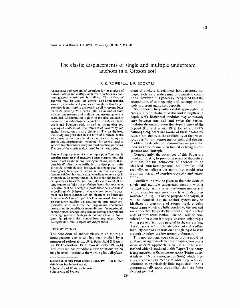
Consideration will be given to the behaviour ofsingle and multiple underream anchors with avertical axis, resting in a non-homogeneous soilwhose modulus increases linearly with depth asindicated in Fig. 1. For the purpose of analysis, itwill be assumed that the anchor system may beidealized as consisting of rough, rigid, circularunderreams which are fully bonded to the soil andare connected by perfectly smooth, rigid anchorrods of zero cross-section. The soil will be con-sidered to be either isotropic, or cross-anisotropicwith a plane of isotropy parallel to the soil surface.The soil mass is of infinite lateral extent and is eitherinfinitely deep or else rests on a rough, rigid base ata depth D below the lowermost underream.
This non-homogeneous elastic profile could beanalysed using finite element techniques; however amore efficient approach is to use a finite layermethod which is outlined in this Paper. This theoryis implemented in the program FLANS(Finite LayerAnalysis of Non-homogeneous Soils) which pro-vides a convenient means of obtaining accuratesolutions using relatively little input data, and iscomputationally more economical than the finiteelement method.
125
126
51
R, K, ROWE AND J. R, BOOKER
p
h
+s
+s
t ~B~
o
J/I'///I///I'//I'/I
Rough rigid
E
E=EO+pz
P = [1-E;IEa]
Ea
z
Fig. 1. Typical problem configuration
The results of this study are presented in the formof correction factors which may readily be used inhand calculations for estimating the effect of non-homogeneity or anisotropy upon anchor response,or for predicting the displacement of anchors in anon-homogeneous soil. The use of the correctionfactors is illustrated by a worked example in theAppendix,
It is considered that the solutions presented forsingle underream anchors could also be used toestimate the displacement of circular or near cir-cular buried footings resting in a non-homo-geneous soil. These solutions provide a moregcneral alternative to the use of surface footingsolutions in conjunction with depth correctioncharts such as those of Janbu, Bjerrum & Kjaernsli(1956) or Christian & Carrier (1978).
METHOD OF ANALYSISThe behaviour of elastic, horizontally layered
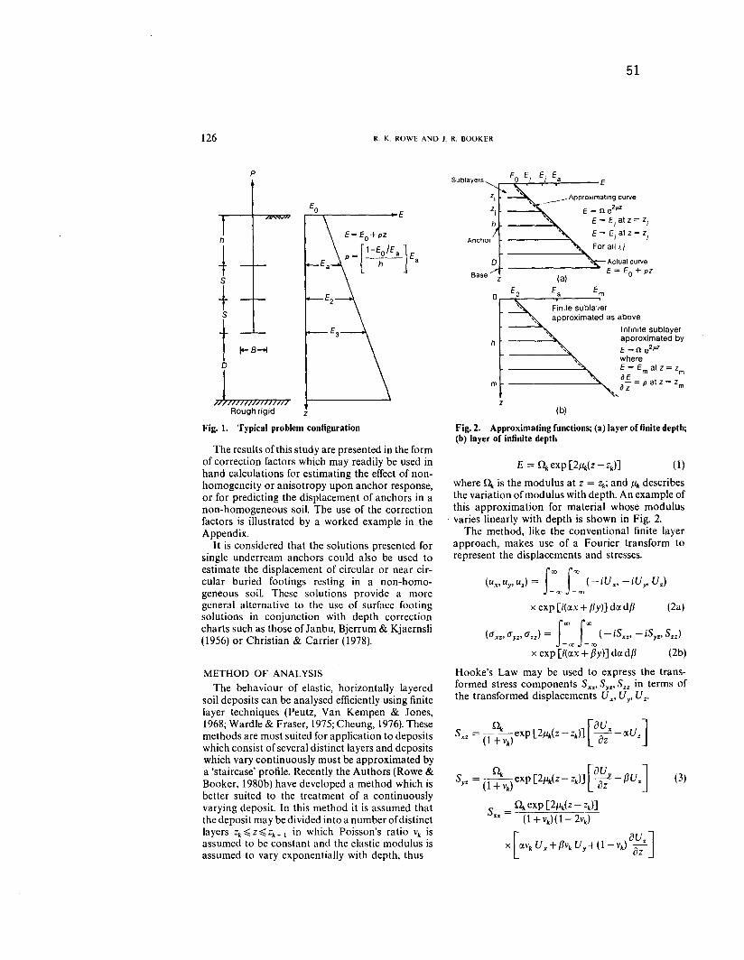
soil deposits can be analysed efficiently using finitelayer techniques (Peutz, Van Kempen & Jones,1968; Wardle & Fraser, 1975; Cheung, 1976). Thesemethods are most suited for application to depositswhich consist of several distinct layers and depositswhich vary continuously must be approximated bya 'staircase' profile. Recently the Authors (Rowe &Booker, 198Gb)have developed a method which isbetter suited to the treatment of a continuouslyvarying deposit. In this method it is assumed thatthe deposit may be divided into a number of distinctlayers Zk~ Z~ Zk+ 1 in which Poisson's ratio Vk isassumed to be constant and the elastic modulus isassumed to vary exponentially with depth, thus
Sublayers
Actual curveE = Eo + pZ
E
Anchor
Approximating curve
" E = n e2pZ
E = E at Z = ZI I
E = E at Z = ZJ J
For all i,i
Base Z
a
h
Finite subla'Jerapproximated as above
Infinite sublayerapproximated by
'\i:, E = n e2p.z
whereE = E at z = zaE
m m
--=p atz= z
~, az mm
z(b)
Fig. 2. Approximating functions; (a) layer of finite depth;(b) layer of infinite depth
(1)
where!1" is the modulus at Z = Zk;and J.l.kdescribesthe variation of modulus with depth. An example ofthis approximation for material whose modulusvaries linearly with depth is shown in Fig. 2.
The method, like the conventional finite layerapproach, makes use of a Fourier transform torepresent the displacements and stresses.
(ux,uy,uz)= f~c<, f~c<,(-iVx' -iVy, Uz)
xcxp[i(ax+fJy)]dlXdfJ (2a)
(ax.. ay.. azz) =f~oo
fO00
(- iSxz' - iSyz' Szz)
x exp [i(lXx+ py)] dlXdp (2b)
Hooke's Law may be used to express the trans-formed stress components Sxz'SyZ'Szz in terms ofthe transformed displacements U
x'Uy' UZ'
!1"[aU
JSyz = (l+vk)exp[2J.i.k(z-zk)] =-g-:-puz
S =!1"exp [2J.1.k(Z- zdJ
zz (l+vk)(I-2vd
x [IXVk Ux+fJvk Uy+(l-vk) a~zJ
(3)
0 0 0
0 0 0
0 0 0
0 0 0
B3 0 0
Bj_1 T Cj_1 +Aj Bj
0 C.-z+A.-, B'_I0 B'_I C._,+A.
VI 0
Vz 0
X U3 0
Vj Tj(6)
U. 0
52
ELASTIC DISPLACEMENTS OF UNDERREAM ANCHORS IN A GIBSON SOIL 127
If equations (2) are substituted into the equilibriumequations it is found that the displacements may beexpressed in the form
U =
[~:
]= ,E ~j jexp [Pjz]
J-I
Vz
where Pj and Vj are known (details of their calcula-tion are given by Rowe & Booker, 1980b) and ~iaresix constants to be determined.
The constants ~i may be calculated in terms ofthe 6 node plane displacements Uk'Vk+ I' Usingthese expressions equation (4) may be substitutedinto equation (3) to obtain the stiffness relation.
where
Tk = +(Sx%,SYZ,Su),.Tis the traction on thenode plane Z = Zk
Tk_
I = - (Sx%'Syz:Su),.\ I is the traction onthe node plane Z= Zk+ I
Uk.l<+1= (Vx, VY' Vz),.T.I<+1are the displace-ments on the node planes Z = Zk.k+ I
and the matrices Ak' Bk, Ck are all known.The conditions of displacement compatibility
and traction equilibrium at the node planes maynow be used to obtain the behaviour of a n layersystem and it is found that
Al BI 0
BIT C,+Az Bz
o BZT CZ+A3
(4)
where for simplicity it has been assumed that thelayered system rests on a rough, rigid base and issubject to stress jump Tj at node plane j.
Equation (6) may now be used to calculate thenode plane displacements U
I'''''U~ for any value ofthe parameters ex,pand so the actual displacementscan be obtained by evaluating equation (2a)numerically. The stress components may be calcu-lated similarly.
(5)
ANCHOR IDEALlZATION AND NUMERICALDETAILS
The basic theory may be generalized to considera number of different boundary conditions at theinterface. However, attention will be restricted hereto the displacement of anchor systems consisting ofrough, rigid anchor plates which are fully bonded tosoil has been discussed by Rowe & Booker (1979a).upon the response of anchors in a homogeneoussoil has been discussed by Row & Booker (1979a).
The overburden pressure gives rise to initialcompressive stresses between the anchor plate andthe soil. Loading the anchor decreases the compres-sive stress beneath the anchor until the stressbecomes zero or tensile; at this point the anchor willbreak away from the underlying soil. The solutionsfor a fully bonded anchor presented in this Paperare valid until this breakaway occurs. Load pathfinite element results (up to collapse) indicate thatunder many circumstances the assumption of afully bonded anchor is valid for working loadscalculated by applying a factor of safety of 3 to thecollapse load (see Rowe & Davis, 1980a, b).
The analysis of a rigid anchor is achieved bysubdividing the anchor into a number of uniformlyloaded ring 'elements'. The number of elementsrequired to achieve 'rigidity' depends on the degreeof non-homogeneity; however, it was found that theload-displacement relationship could be obtainedto sufficient accuracy by subdivision of the anchorinto four annular rings. Further subdivision of theanchor typically altered the displacement by lessthan 3%. Twelve subdivisions gave an accuracy ofbetter than 1% for problems where analyticalsolutions were known.
An alternative approach to the subdivision of theanchor into uniformly loaded elements is to con-sider the average displacement of an anchor whichca uses a vertical stress jump given by the expression
1a.(r) = nB.J[(Bz/2)-rZ]
0<r<B/2
= 0 elsewhere. (7)
This approach allows considerable computationalsavings and was found to give excellent results. Fora homogeneous soil, this approach agrees exactlywith the analytic solutions for the limiting cases of asurface footing and an infinitely deep anchor. For
128
53
R. K. ROWE AND 1. R. BOOKER
2.0
1.8
p
h
t1.6
o
///////////////~
1.2
0,8o 2 3
h
B
4 0.15 0.1 0.0550.2 1i
h
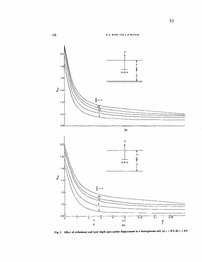
Fig. 3. Effect of embedment and layer depth upon anchor displacement in a homogeneous soil; (a) v =0.3; (b) v =
0,5
(b)
ELASTIC DISPLACEMENTS OF UNDERREAM ANCHORS IN A GIBSON SOIL
intermediate embedments, the approach givessimilar solutions to those obtained by subdivisionof the footing into twelve elements and may beregarded as being more accurate than solutionsobtained using only four subdivisions. The errorsinvolved in the use of this stress jump are greatestfor shallow anchors resting in a highly non-homo-geneous incompressible soil, however even in thesecases a comparison with the results obtained foranchors divided into uniformly loaded elementssuggests that the approximate approach is accurateto within 2%. The majority of results reported inthis Paper were obtained using this approximateapproach. These solutions were checked againstresults obtained with up to twelve annularelements.
A second numerical approximation arises fromthe use of an exponential function to represent thelinear increase in modulus with depth. Theaccuracy of this approximation depends upon thevariation in modulus between the top and bottomof each layer. If the ratio is considered to be toolarge for a particular layer then the layer may besplit into sublayers. The results presented in thisPaper were obtained for a maximum ratio of amodulus between the top and bottom of each layerof 1.25. This ensures that the error in the repre-sentation of the soil modulus is always less than0.4%. This is a very conservative numerical restric-tion but was adopted to ensure consistentlyaccurate results. In practice one may performanalyses for modulus ratio of 1.5 withoutappreciably altering the results and much highermodulus ratios may be adopted without significanterror for layers more than two footing widths(diameters) below the footing. For layers of infinitedepth the tangential exponential approximation(see Fig. 2) was used at a distance of 20 anchordiameters below the lowest underream. Increasingthis distance had no significant elTect upon theanchor response.
The analysis was validated by comparison withpublished solutions and the results of the Author'sfinite element analyses. Good agreement wasobtained with the published results for anchors in ahomogeneous soil (Selvadurai, 1976; Rowe &Booker, 1980a) and for footings upon a soil with alinearly increasing modulus with depth (Brown &Gibson, 1979). Agreement to better than 1% wasalso obtained between this method and finiteelement calculation for a number of non-homogeneous soil profiles. The finite elementresults required considerably greater data prepara-tion time and were computationally moreexpensive. The advantage ofthe Author's approachover finite elements increased rapidly with in-creasing number and spacing of underreams andlayer depth.
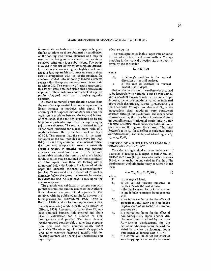
SOIL PROFILE
The results presented in this Paper were obtainedfor an ideal, elastic soil mass with a Young'smodulus in the vertical direction E" at a depth z,given by the expression
Ev=Eo+pzwhere
Eo is Young's modulus in the verticaldirection at the soil surface;
P is the rate of increase in verticalmodulus with depth.
Unless otherwise stated, the soil may be assumedto be isotropic with variable Young's modulus Evand a constant Poisson's ratio v. For anisotropicdeposits, the vertical modulus varied as indicatedabove while the ratios Eh/Evand Ghv/Ev(where Eh isthe horizontal Young's modulus and Gvh is theindependent shear modulus) were consideredconstant throughout the deposit. The independentPoisson's ratio Vh(for the elTectof horizontal stresson complimentary horizontal strain) and vvh (forthe elTectof vertical stress on horizontal strain) werealso constant throughout the stratum. The thirdPoisson's ratio Vhv(for the elTectof horizontal stresson vertical strain) is not independent and is given byVhv = vvhEh/Ev.
RESPONSE OF A SINGLE UNDERREAM IN ANON-HOMOGENEOUS SOIL
Consider a single, rigid circular underream ofdiameter B resting at a depth h below the soilsurface with a rough rigid base at a further distanceD below the anchor as indicated in Fig. 3(a). Thedisplacement b of this anchor may be written in theform
wherep
Eais the applied load;is the vertical Young's modulus atdepth It below the soil surface;is the displacement factor for an anchorin an infinite isotropic homogeneoussoil;is an influence factor for the elTect ofembedment and layer depth upon thedisplacement of an anchor in a homo-geneous soil;is a correction factor for the elTect ofnon-homogeneity upon anchor dis-placement and is defined by the ratioRN = anchor displacement for theactual non-homogeneous deposit di-vided by anchor displacement for ahomogeneous deposit with E = Ea;is a correction factor for the elTect ofanisotropy upon anchor displacement
54
129
(8)
6,0
z 3Q;
0-8
0.7
0,60 0'2 0'4 0-6 0'8 1.0.
EoE.
(b)
130
55
R. K. ROWE AND J. R. BOOKER
10
3
0,9 3
zQ;0.8
oB
0.7 - - - --3
0-6(a)
II = 20B
10 =- -"':3 -_ -:... _ =:=. -=..-==--=--=- A20 /.
oB
_ 3
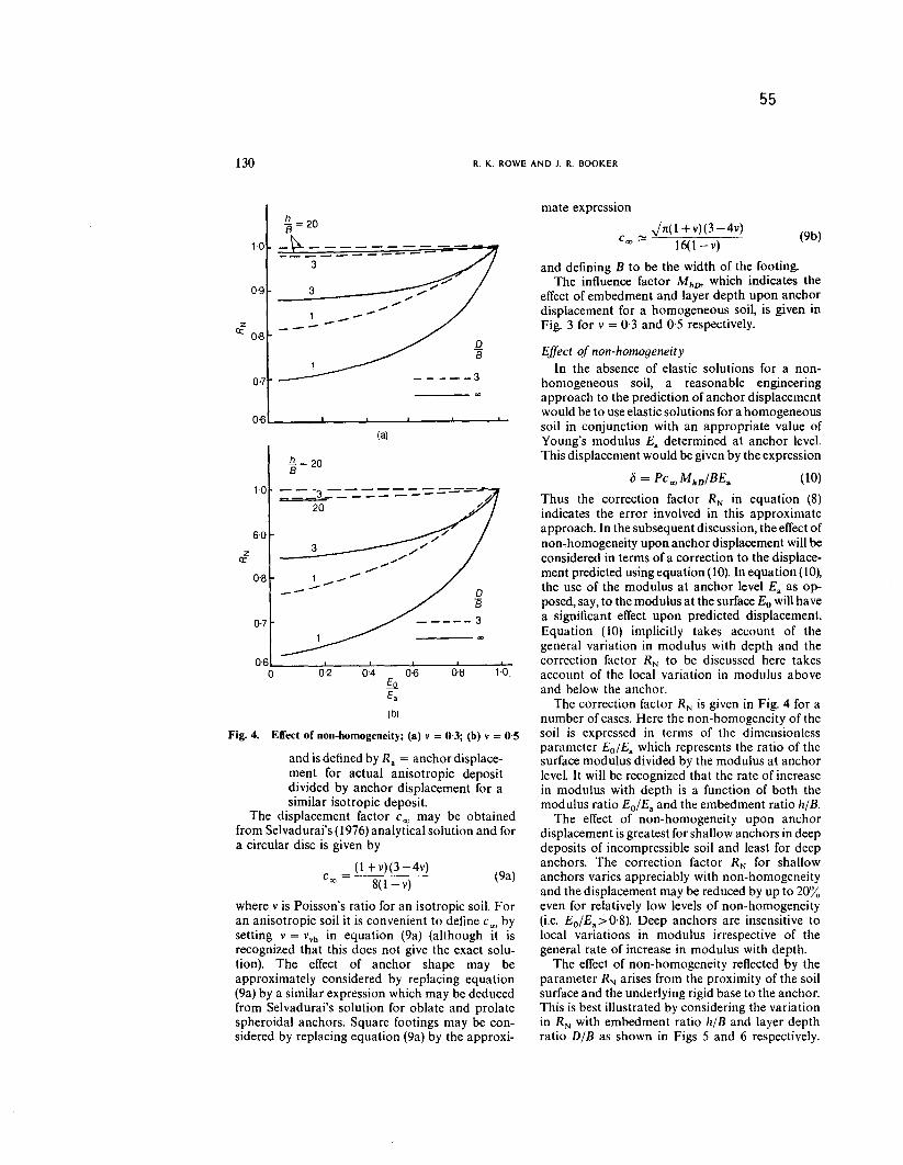
Fig.4. Effectof non-homogeneity;(a) v = 0-3; (b) v = 0,5
and is defined by R. = anchor displace-ment for actual anisotropic depositdivided by anchor displacement for asimilar isotropic deposit.
The displacement factor Coomay be obtainedfrom Selvadurai's (1976) analytical solution and fora circular disc is given by
(1 +v)(3-4v)c =00 8(I-v)
where v is Poisson's ratio for an isotropic soil. Foran anisotropic soil it is convenient to define Coobysetting v = vvh in equation (9a) (although it isrecognized that this does not give the exact solu-tion). The effect of anchor shape may beapproximately considered by replacing equation(9a)by a similar expression which may be deducedfrom Selvadurai's solution for oblate and prolatespheroidal anchors. Square footings may be con-sidered by replacing equation (9a) by the approxi-
mate expression
";1(1 +v)(3-4v)Coo~ 16(I-v)-
and defining B to be the width of the footing.The influence factor MhDo which indicates the
effect of embedment and layer depth upon anchordisplacement for a homogeneous soil, is given inFig. 3 for v = 0,3 and 0,5 respectively.
(9b)
(9a)
Effect of non-homogeneity
In the absence of elastic solutions for a non-homogeneous soil, a reasonable engineeringapproach to the prediction of anchor displacementwould be to use elastic solutions for a homogeneoussoil in conjunction with an appropriate value ofYoung's modulus E. determined at anchor level.This displacement would be given by the expression
{j = Pc 00MhD/BE. (10)
Thus the correction factor RN in equation (8)indicates the error involved in this approximateapproach. In the subsequent discussion, the effect ofnon-homogeneity upon anchor displacement will beconsidered in terms of a correction to the displace-ment predicted using equation (10). In equation (10),the use of the modulus at anchor level E. as op-posed, say, to the modulus at the surface Eo will havea significant effect upon predicted displacement.Equation (10) implicitly takes account of thegeneral variation in modulus with depth and thecorrection factor RN to be discussed here takesaccount of the local variation in modulus aboveand below the anchor.
The correction factor RN is given in Fig. 4 for anumber of cases. Here the non-homogeneity of thesoil is expressed in terms of the dimensionlessparameter Eo/E.which represents the ratio of thesurface modulus divided by the modulus at anchorlevel. It will be recognized that the rate of increasein modulus with depth is a function of both themodulus ratio Eo/E. and the embedment ratio h/B.
The effect of non-homogeneity upon anchordisplacement is greatest for shallow anchors in deepdeposits of incompressible soil and least for deepanchors. The correction factor RN for shallowanchors varies appreciably with non-homogeneityand the displacement may be reduced by up to 20%even for relatively low levels of non-homogeneity(i.e. Eo/E.> 0,8). Deep anchors are insensitive tolocal variations in modulus irrespective of thegeneral rate of increase in modulus with depth.
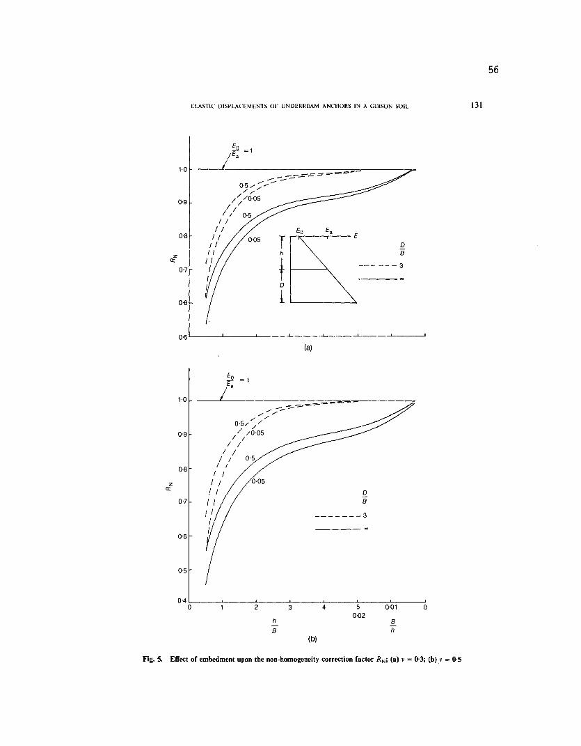
The effect of non-homogeneity reflected by theparameter RN arises from the proximity of the soilsurface and the underlying rigid base to the anchor.This is best illustrated by considering the variationin RN with embedment ratio h/B and layer depthratio D/B as shown in Figs 5 and 6 respectively.
ELASTIC DISPLACEMENTS OF UNDERREAM ANCHORS IN A GIUSON SOIL
zII:
0'7
zII:
,- -~-=--=-.=:;:::-=-'=="$&'"0'5/"" ""
'"
/
/' /'
/ /0'05
I/
/I / 0.5/ I
/ /II
I /II
IIIII
- -==--,.,.;",..-",/ ,/
0.5//'"/ /0'05/ /
/ I/ I
/ /I I
I /I I
I I 0
II B
I I __ _ _ _ _ _ 3II
1.0
Th
to
1
oB
-- - - - - 3
o.g
0'8
0-6
0'5
EO= 1
E.
1.0
o.g
0'8
0'7
E
(a)
3 4 50{)2
o
0'6
0.5
0'4o 2 0,01
h
B
Bh
Fig. 5. Effect of embedment upon the non-homogeneity correction factor RN; (a) v = 0'3; (b) v=
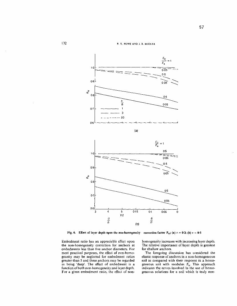
Fig. 6. Effect of layer depth upon the non-homogeneity correction factor RN; (a) v = 0,3; (b) v= O'S
Embedment ratio has an appreciable effect uponthe non-homogeneity correction for anchors atembedments less than five anchor diameters. Formost practical purposes, the effect of non-homo-geneity may be neglected for embedment ratiosgreater than 5 and these anchors may be regardedas being 'deep'. The effect of embedment is afunction of both non-homogeneity and layer depth.For a given embedment ratio, the effect of non-
homogeneity increases with increasing layer depth.The relative importance of layer depth is greatestfor shallow anchors.
The foregoing discussion has considered theelastic response of anchors in a non-homogeneoussoil as compared with their response in a homo-geneous soil with modulus Ea. This approachindicates the errors involved in the use of homo-geneous solutions for a soil which is truly non-
ELASTIC DISPLACEMENTS OF UNDERREAM ANCHORS IN A GIBSON SOIL 133
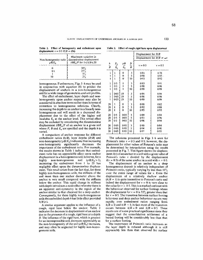
Table 1. Effect of homogeneity and embedment upondisplacement: v = 0,3 D/B = 00
Non-homogeneity ratiopB/Eo
o0.11
\0
Maximum variation indimensionless displacement
oBE./P for l~h/B~20
38%25~~
5/;"2%
homogeneous. Furthermore, Figs 3-6 may be usedin conjunction with equation (8) to predict thedisplacement of anchors in a non-homogeneoussoil for a wide range of geometries and soil profiles.
The effect of embedment, layer depth and non-homogeneity upon anchor response may also beconsidered in absolute terms rather than in terms ofcorrection to homogeneous solutions. Clearly,increasing the depth to an anchor in a linearly non-homogeneous soil will result in a decreased dis-placement due to the effect of the higher soilmodulus E. at the anchor level. This trivial effectmay be excluded by considering the dimensionlessdisplacement oBE.IP of an anchor in a given soilwhere P, B and E. are specified and the depth h isvaried.
A comparison of anchor response for differentembedment ratios (hIB), layer depths (D/B) andnon-homogeneity (pB/Eo) indicates that increasingnon-homogeneity significantly decreases theimportance of the embedment ratio. For example,the results shown in Table 1 indicate that embed-ment ratio has an appreciable effect upon anchordisplacement in a homogeneous soil; however, for ahighly non-homogeneous soil (pB/Eo> 1),increasing the embedment from 1 to 20 hasnegligible effect upon the dimensionless displace-ment. This result arises from the fact that, for thesehighly non-homogeneous soils, the stiffness of thesoil more than one anchor diameter above theanchor is very small compared with the stiffnessbelow the anchor. This rapid change in stiffnesswith depth introduces a scale effect whereby there isan apparent anti-symmetry in the region of theanchor similar to that observed for a deep anchor.Consequently, for these highly non-homogeneoussoils the embedded depth h has little effect providedhi B ~ 1.
A similar argument applies to the influence of arough, rigid base below the anchor. Table 2indicates the decrease in displacement of an anchordue to the presence of a rough, rigid base at a depthD. The influence of the rigid base, which is greatestfor an incompressible soil, decreases appreciably asthe non-homogeneity of the soil (pB/Eo) increases,and may often be neglected for highly non-homo-geneous soils.
Table 2. Effect of rough rigid base upon displacement
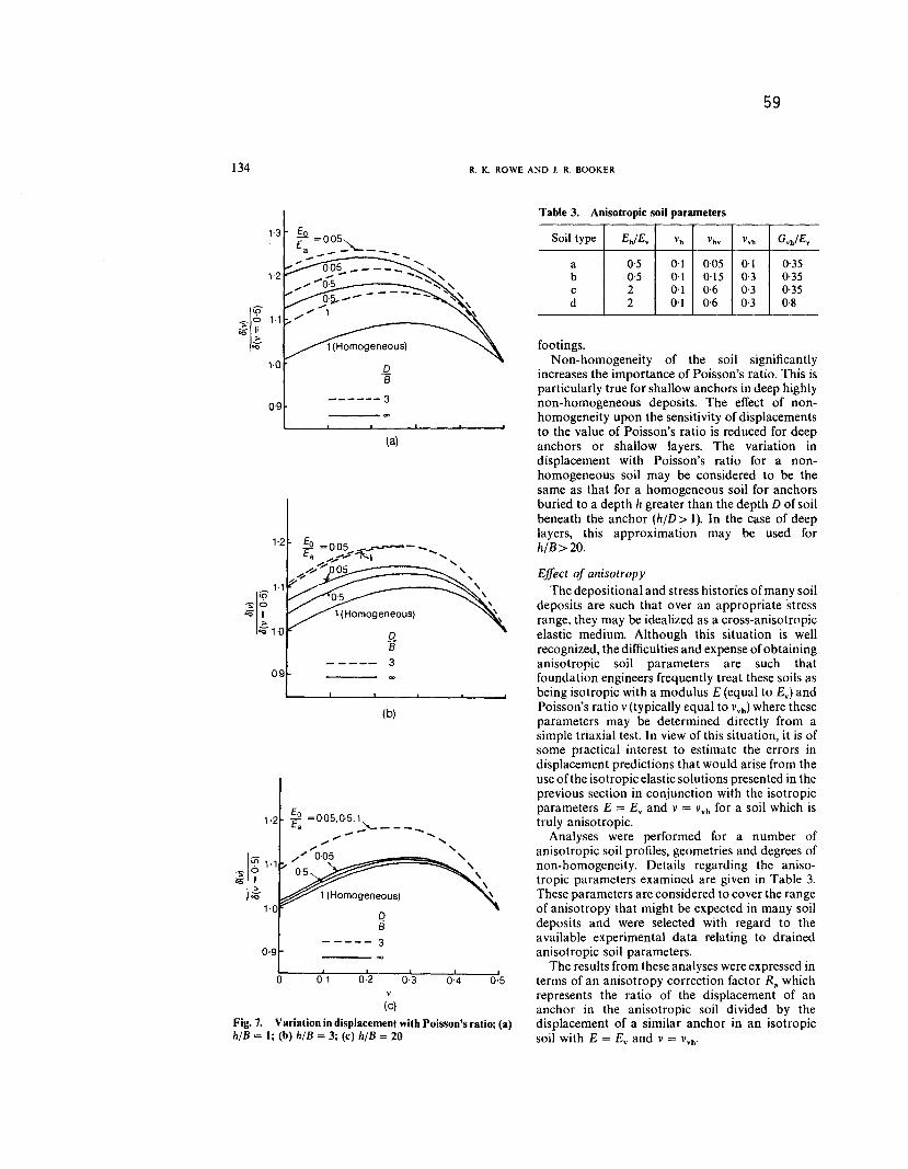
The solutions presented in Figs 3-6 were forPoisson's ratio v = 0,3 and 0.5; however, the dis-placement for other values of Poisson's ratio maybe determined by interpolation using the resultspresented in Fig. 7. This figure shows the displace-ment o(v) of an anchor in a soil with a given value ofPoisson's ratio v divided by the displacemento(v = 0'5) of the same anchor in a soil with v = 0'5'-
The displacement of an anchor in a deephomogeneous deposit is relatively independent ofPoisson's ratio, typically varying by less than 11%over the entire range of values for v. Even thedisplacement of a relatively shallow anchor(h/B = 1) is quite insensitive to Poisson's ratio andindeed the displacement for v = 0 is very close tothe value for v = 0,5. This is a marked contrast with
the behaviour observed for surface footings wherethe displacement for v = 0 is 33% greater than thatfor v = 0,5. The transition between surface footingbehaviour and deep anchor behaviour occurs veryrapidly over embedment ratios ranging fromhlB = 0 and h/B = 1; in fact most of the transitionoccurs between hlB = 0 and h/B = 0,5. Theseresults are of some practical significance since theysuggest that the consolidation settlement of aburied footing will be considerably less than thatfor a surface footing.
The importance of Poisson's ratio increases asthe layer depth is reduced although it is stillappreciably less than that observed for surface
Fig. 7. Variation in displacement with Poisson's ratio; (a)h/B = I; (b) h/B = 3; (c) h/B = 20
Table 3. Anisotropic soil parameters
footings.Non-homogeneity of the soil significantly
increases the importance of Poisson's ratio. This isparticularly true for shallow anchors in deep highlynon-homogeneous deposits. The effect of non-homogeneity upon the sensitivity of displacementsto the value of Poisson's ratio is reduced for deepanchors or shallow layers. The variation indisplacement with Poisson's ratio for a non-homogeneous soil may be considered to be thesame as that for a homogeneous soil for anchorsburied to a depth IIgreater than the depth D of soilbeneath the anchor (IIID> 1). In the case of deeplayers, this approximation may be used forIIIB> 20.
0'5
Effect of anisotropyThe depositional and stress histories of many soil
deposits are such that over an appropriate 'stressrange, they may be idealized as a cross-anisotropicelastic medium. Although this situation is wellrecognized, the difficulties and expense of obtaininganisotropic soil parameters are such thatfoundation engineers frequently treat these soils asbeing isotropic with a modulus E (equal to E.) andPoisson's ratio v (typically equal to v.h) where theseparameters may be determined directly from asimple triaxial test. In view of this situation, it is ofsome practical interest to estimate the errors indisplacement predictions that would arise from theuse of the isotropic elastic solutions presented in theprevious section in conjunction with the isotropicparameters E = E. and v = V.hfor a soil which istruly anisotropic.
Analyses were performed for a number ofanisotropic soil profiles, geometries and degrees ofnon-homogeneity. Details regarding the aniso-tropic parameters examined are given in Table 3.These parameters are considered to cover the rangeof anisotropy that might be expected in many soildeposits and were selected with regard to theavailable experimental data relating to drainedanisotropic soil parameters.
The results from these analyses were expressed interms of an anisotropy correction factor R. whichrepresents the ratio of the displacement of ananchor in the anisotropic soil divided by thedisplacement of a similar anchor in an isotropicsoil with E = E. and v = V.h.
Anisotropy ratioh D Displacement (anisotropic)- - R =B B . Displacement (isotropic)
ELASTIC DISPLACEMENTS OF UNDI'RREAM ANCHORS IN A GillSON SOIL 135
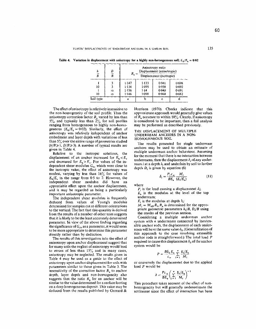
Table 4. Variation in displacement with anisotropy for a highly non-homogeneous soil; Eo/E. = 0.02
The effect of anisotropy is relatively insensitive tothe non-homogeneity of the soil profile. Thus theanisotropy correction factor R. varied by less than5%, and typicalIy less than 2%, for soil profilesranging from homogeneous to highly non-homo-geneous (Eo/E. = 0'02). Similarly, the effect ofanisotropy was relatively independent of anchorembedment and layer depth with variations of lessthan 5% over the entire range of geometries studied(h/B~ 1, D/B~3). A number of typical results aregiven in Table 4.
Relative to the isotropic solutions, thedisplacement of an anchor increased for Eh< Eyand decreased for Eh> Ey. For values of the in-dependent shear modulus Ghvwhich were close tothe isotropic value, the effect of anisotropy wasmodest, varying by less than 16% for values ofEh/Ey in the range from 0,5 to 2. However, theindependent shear modulus did have anappreciable effect upon the anchor displacement,and it may be regarded as being a particularlyimportant anisotropic parameter.
The independent shear modulus is frequentlydeduced from values of Young's modulusdetermined for samples cut at different orientationsto the vertical. The fact that this quantity is deriwdfrom the results of a number of other tests suggeststhat it is likely to be the least accurately determinedparameter. In view of the above finding regardingthe significance of GYhas a parameter, it would seemto be more appropriate to determine this parameterdirectly rather than by deduction.
The results of this investigation into the elTectofanisotropy upon anchor displacement suggest thatfor many soils the neglect of anisotropy would leadto errors of less than 15% and in many cases,anisotropy may be neglected. The results given inTable 4 may be used as a guide to the elTect ofanisotropy upon anchor displacement for soils withparameters similar to those given in Table 3. Theinsensitivity of the correction factor R. to anchordepth, layer depth and non-homogeneity alsosuggests that the ratio R. for an anchor wilI besimilar to the value determined for a surface footingon a deep homogeneous deposit. This value may bededuced from the results published by Gerrard &
Harrison (1970). Checks indicate that thisapproximate approach would generally give valuesof R. accurate to within 10%. Clearly, if anisotropyis considered to be important, then a full analysismay be performed as described previously.
THE DISPLACEMENT OF MULTIPLEUNDERREAM ANCHORS IN A NON-HOMOGENEOUS SOIL
The results presented for single underreamanchors may be used to obtain an estimate ofmultiple underream anchor behaviour. Assumingfor the moment that there is no interaction betweenunderreams, then the displacement bj of any under-ream i at a depth Iljand underlain by soil to furtherdepth Dj is given by equation (8)
(11)
wherePi is the load causing a displacement bj;E. is the modulus at the level of the topunderream;Ej is the modulus at depth hi;Mj = MhDRN R. is determined for the appro-priate geometric parameters hJB, DJB usingthe results of the previous section.Considering a multiple underream anchor
system with n underreams connected by inexten-sible anchor rods, the displacement of each under-ream will have the same value bo. (Generalization ofthis approach to the case involving extensibleanchor rods is straightforward.) The total load Prequired to cause this displacement bo of the anchorsystem would be
P =B(jo E. i EJ E.
COO j= 1 Mj
or conversely the displacement due to the appliedload P would be
b = PCoo (i EJE.)-I
BE. j=1 Mj
This procedure takes account of the elTect of non-homogeneity but wiII generally underestimate thesettlement since the effect of interaction has been
136
2-0
61
R. K. ROWE AND J. R. BOOKER
2 UndeITeams
\\'\
'~- -- - - - - - - -- - -
2'S p
2.0
1'S
1.0
2.0
2'S
4 UndeITeams
h
+s+si..
z
2 Underreams
4 Underrearms
\\\
\~\
\~"~ --::::-:--~------
2 4 6 8 10 O{)S0-1
3 UndeITeams
2.0
1'S
sB
BS
~
\\
\,"-~-~-
S Underreams
--o.S
------- O.OS
(a)
3 Underreams
\\\\
\ ,"-.........-
--------
S Underreams
-o.S
- - - - - - - O'OS
o o 2 4 6 8 100-1
O-oS o
sB
BS
Fig.8. Interaction factor; (a) for hlB = 1, DIB = 00, v = 0,5; (b) for hlB = 10, DIB = 00, v = 0,5
(b)
62
ELASTIC DISPLACEMENTS OF UNDFRRFAM ANCHORS IN A GillSON SOIL 137
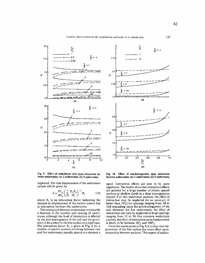
Fig. 9. Effect of embedment ratio upon interaction be-tween underreams; (a) 2 underreams; (b) 5 underreams
neglected. The true displacement of the underreamsystem will be given by
fJ=Pc",(~ EJEa_ )
-1Rf (12)
BEa 1=1 Mj
where Rf is an interaction factor indicating theincrease in displacement of the anchor system dueto interaction between the underreams.
The interaction between underreams is primarilya function of the number and spacing of under-reams, although the level of interaction is affectedby the non-homogeneity of the soil and the proxi-mity of the anchor to the free surface or a rigid base.The interaction factor Rf is given in Fig. 8 for anumber of anchor systems involving between twoand five underreams, equally spaced at a distance s
hB
1-75 10
1.5 ~ =1B
1.25 -f"=-2---B
~ = 10B___ ______-----1.0
(a)
2-5
§.= 1B
2.0~=2 -3___ ---
1.5§.
= 10B ---------1-0
o 02 0'4 0,6 0-8 1.010
(b)
Fig. 10. Effect of non-homogeneity upon interactionbetween underreams; (a) 2 underreams; (b) 5 underreams
apart. Interaction effects are seen to be quitesignificant. The results show that interaction effectsare greatest for a large number of closely spacedanchors at shallow depth in a deep homogeneousdeposit. For two underream anchors, the effect ofinteraction may be neglected (to an accuracy ofbetter than 10%) for spacings ranging from 3B tolOB depending upon the non-homogeneity of thesoil. However for five underreams, the effect ofinteraction can only be neglected at large spacingsranging from 12 to 20. For common underreamsystems, the effect of interaction upon displacementis likely to be between 10% and 100%.
From the results given in Fig. 8, it is clear that theproximity of the free surface has some effect uponinteraction between anchors. This aspect of anchor
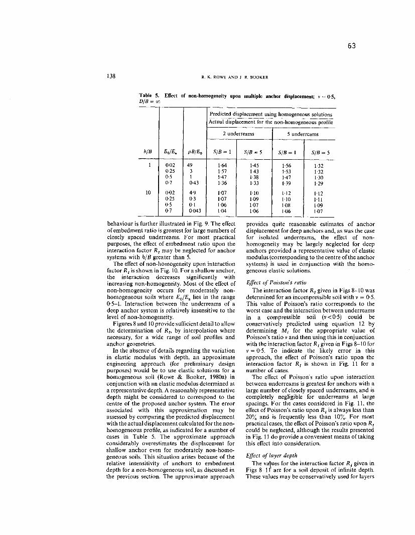
Predicted displacement using homogeneous solutions
Table 5. Effect of non-homogeneity upon multiple anchor displacement; v= 0'5,
D/B = 00
behaviour is further illustrated in Fig. 9. The effectof embedment ratio is greatest for large numbers ofclosely spaced underreams. For most practicalpurposes, the effect of embedment ratio upon theinteraction factor R[ may be neglected for anchorsystems with h/B greater than 5.
The effect of non-homogeneity upon interactionfactor R[ is shown in Fig. 10. For a shallow anchor,the interaction decreases significantly withincreasing non-homogeneity. Most of the effect ofnon-homogeneity occurs for moderately non-homogeneous soils where Eo/ Ea lies in the range0'5-1. Interaction between the underreams of adeep anchor system is relatively insensitive to thelevel of non-homogeneity.
Figures 8 and 10 provide sufficient detail to allowthe determination of R[, by interpolation wherenecessary, for a wide range of soil profiles andanchor geometries.
In the absence of details regarding the variationin elastic modulus with depth, an approximateengineering approach (for preliminary designpurposes) would be to use elastic solutions for ahomogeneous soil (Rowe & Booker, 1980a) inconjunction with an elastic modulus determined ata representative depth. A reasonably representativedepth might be considered to correspond to thecentre of the proposed anchor system. The errorassociated with this approximation may beassessed by comparing the predicted displacementwith the actual displacement calculated for the non-homogeneous profile, as indicated for a number ofcases in Table 5. The approximate approachconsiderably overestimates the displacement forshallow anchor even for moderately non-homo-geneous soils. This situation arises because of therelative insensitivity of anchors to embedmentdepth for a non-homogeneous soil, as discussed inthe previous section. The approximate approach
provides quite reasonable estimates of anchordisplacement for deep anchors and, as was the casefor isolated underreams, the effect of non-homogeneity may be largely neglected for deepanchors provided a representative value of elasticmodulus (corresponding to the centre of the anchorsystems) is used in conjunction with the homo-geneous elastic solutions.
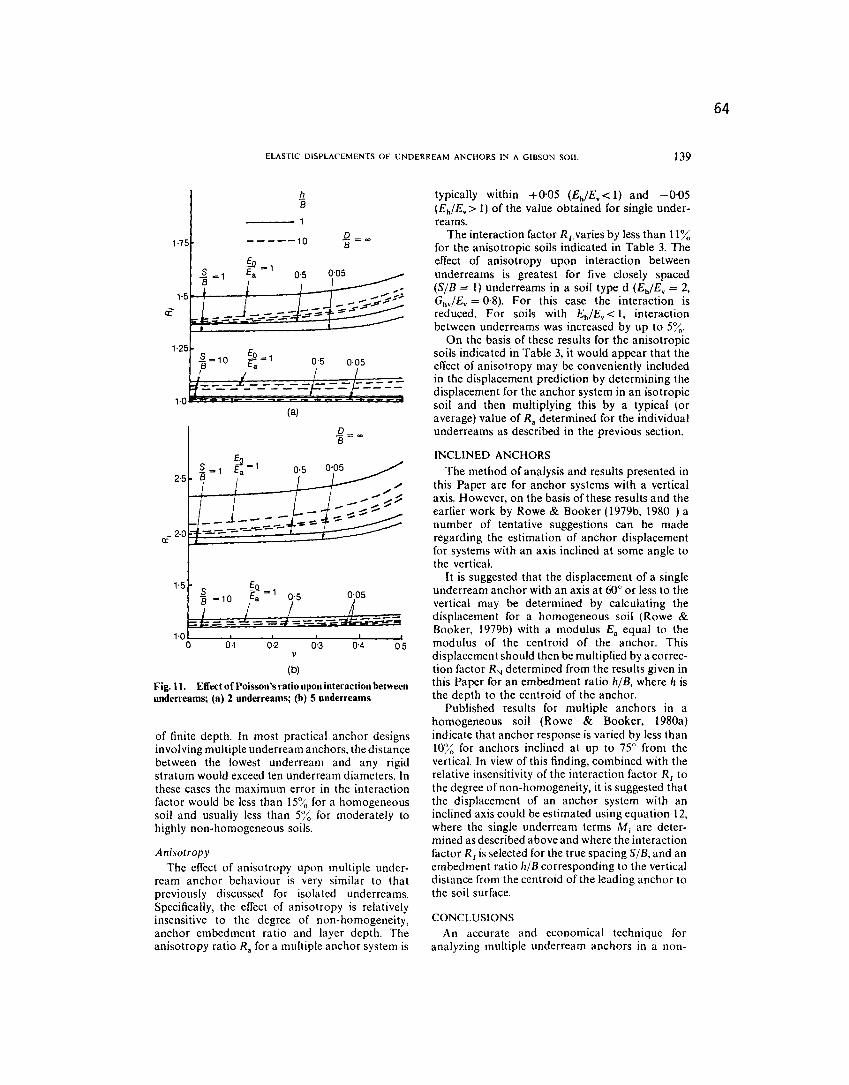
Effect of Poisson's ratioThe interaction factor R[ given in Figs 8-10 was
determined for an incompressible soil with v = 0,5.
This value of Poisson's ratio corresponds to theworst case and the interaction between underreamsin a compressible soil (v<0'5) could beconservatively predicted using equation 12 bydetermining Mj for the appropriate value ofPoisson's ratio v and then using this in conjunctionwith the interaction factor R[ given in Figs 8-10 forv = 0,5. To indicate the likely error in thisapproach, the effect of Poisson's ratio upon theinteraction factor R[ is shown in Fig. 11 for anumber of cases.
The effect of Poisson's ratio upon interactionbetween underreams is greatest for anchors with alarge number of closely spaced underreams, and iscompletely negligible for underreams at largespacings. For the cases considered in Fig. 11, theeffect of Poisson's ratio upon R[ is always less than20% and is frequently less than 10%. For mostpractical cases, the effect of Poisson's ratio upon R[could be neglected, although the results presentedin Fig. 11 do provide a convenient means of takingthis effect into consideration.
Effect of layer depthThe va\ues for the interaction factor R[ given in
Figs 8-11 are for a soil deposit of infinite depth.These values may be conservatively used for layers
ELASTIC DISPLACEMENTS OF UNDERREAM ANCHORS IN A GIBSON SOIL
hB
1-75 - - ---10
~ =1B1.5
(a)
oB = co
~ =12.5 B
----""'=--
__",=-0:=---
1.5
0.1 0.2 0.3 0.4v
(b)
Fig. 11. Effect of Poisson's ratio upon interaction betweenunden-eams; (a) 2 underreams; (b) 5 underreams
of finite depth. In most practical anchor designsinvolving multiple underream anchors, the distancebetween the lowest underream and any rigidstratum would exceed ten underream diameters. Inthese cases the maximum error in the interactionfactor would be less than 15~<,for a homogeneoussoil and usually less than 5% for moderately tohighly non-homogeneous soils.
Anisotrop yThe effect of anisotropy upon multiple under-
ream anchor behaviour is very similar to thatpreviously discussed for isolated underreams.Specifically, the effect of anisotropy is relativelyinsensitive to the degree of non-homogeneity,anchor embedment ratio and layer depth. Theanisotropy ratio Ra for a multiple anchor system is
typically within +0,05 (EhIEv< 1) and -0,05(EhIEv> 1) of the value obtained for single under-reams.
The interaction factor R[.varies by less than 11%for the anisotropic soils indicated in Table 3. Theeffect of anisotropy upon interaction betweenunderreams is greatest for five closely spaced(SIB = 1) underreams in a soil type d (EhiEv = 2,GhvlEv = 0,8). For this case the interaction isreduced. For soils with EhlEv < 1, interactionbetween underreams was increased by up to 5%.
On the basis of these results for the anisotropicsoils indicated in Table 3, it would appear that theeffect of anisotropy may be conveniently includedin the displacement prediction by determining thedisplacement for the anchor system in an isotropicsoil and then multiplying this by a typical (oraverage) value of Ra determined for the individualunderreams as described in the previous section.
;;;
INCLINED ANCHORSThe method of analysis and results presented in
this Paper are for anchor systems with a verticalaxis. However, on the basis of these results and theearlier work by Rowe & Booker (1979b, 1980 ) anumber of tentative suggestions can be maderegarding the estimation of anchor displacementfor systems with an axis inclined at some angle tothe vertical.
It is suggested that the displacement of a singleunderream anchor with an axis at 60° or less to thevertical may be determined by calculating thedisplacement for a homogeneous soil (Rowe &Booker, 1979b) with a modulus Ea equal to themodulus of the centroid of the anchor. Thisdisplacement should then be multiplied by a correc-tion factor RN determined from the results given inthis Paper for an embedment ratio hlB, where h isthe depth to the centroid of the anchor.
Published results for multiple anchors in ahomogeneous soil (Rowe & Booker, 1980a)indicate that anchor response is varied by less than10% for anchors inclined at up to 75° from thevertical. In view of this finding, combined with therelative insensitivity of the interaction factor R, tothe degree of non-homogeneity, it is suggested thatthe displacement of an anchor system with aninclined axis could be estimated using equation 12,where the single underream terms Mj are deter-mined as described above and where the interactionfactor R[ is selected for the true spacing SIB, and anembedment ratio hlB corresponding to the verticaldistance from the centroid of the leading anchor tothe soil surface.
05
CONCLUSIONSAn accurate and economical technique for
analyzing multiple underream anchors in a non-
64
139
140
65
R. K. ROWE AND J. R. BOOKER
homogeneous soil has been outlined. The methodof analysis may be used for quite general non-homogeneous, anisotropic elastic soil profilesalthough in this Paper attention is restricted toanchors in a soil whose modulus increases linearlywith depth.
The behaviour of an isolated underream (orburied footing) was examined. Consideration wasgiven to the depth of embedment, layer depth, andthe degree of non-homogeneity. From these results,the following was concluded.
(a) The effect of non-homogeneity is greatestfor shallow anchors in deep deposits, and leastfor deep anchors.(b) Anchor response is highly dependent uponembedment ratio for anchors with an embed-ment ratio less that 5 in a soil with relativelylow non-homogeneity.(c) For most practical purposes, an anchorwith an embedment ratio greater than 5 maybe regarded as being deep and the proximity tothe soil surface may be neglected.(d) Anchors in highly non-homogeneous soilsare insensitive to the proximity ofa free surfacefor embedment ratios greater than I.(e) A rough, rigid base less than ten diametersbelow an anchor has an appreciable effectupon anchor response for soil of relatively lowhomogeneity. Layer depth is a secondaryparameter for highly non-homogeneous soils.(I) Poisson's ratio has a small effect uponanchor displacement for all but very shallowanchors and it is suggested that the consolida-tion settlement of buried footings will beconsiderably less than that for surfacefootings.(g) Anisotropy has relatively little effect uponanchor response for many typical soil profileswhere the independent shear modulus is notappreciably different from the isotropic value.The independent shear modulus is an impor-tant parameter and may significantly influencethe anchor response. It is suggested that, wherepossible, this parameter should be measureddirectly rather than deduced from otherquantities as is common practice.
The displacement of multiple underreamanchors may be predicted using the results forsingle underreams in conjunction with a series ofinteraction factors. From the study of multipleunderream behaviour, the following is concluded.
(a) For common underream systems, the effectof interaction upon displacement is likely to bebetween 10;', and 100/;".(b) The effect of proximity to the soil surfaceupon underream interaction may be neglectedfor embedment ratios greater than 5. Inter-action between underreams for these deep
anchors is relatively insensitive to the level ofnon-homogeneity.(c) Interaction is greatest for anchors in anincompressible soil; however the influence ofPoisson's ratio upon interaction is modest forclosely spaced underreams, and may beneglected at large spacings.
Parametric solutions are presented in the form ofintluence charts which may be used directly in handcalculations to predict the elastic load-detlexionbehaviour of single and multiple underreamanchors for a wide range of parameters.
ACKNOWLEDGEMENTThe work described in this Paper was supported
by grant no. AlO07 from the Natural Science andEngineering Research Council of Canada.
REFERENCES
Brown, P. T. & Gibson, R. E. (1979). Swface settlements ofa finite elastic layer whose modulus increase linearlywith depth. Int. J. Num. Analyt. Meth. Geomech. 3,No. I, 37-47.
Butterfield, R. & Bannerjee, P. K. (1971). A rigid discembedded in an elastic half-space. Geotech. £lIgllg 2, I35-53.
Cheung, Y. K. (1976). Finite .~trip melhod in structuralmechanics. Oxford: Pergamon.
Christian, J. T. & Carrier, W. D. (1978). Janbu, Bjerrumand Kjaernsli's chart reinterpreted. Can. Geotech. J.15, No. I, 123-127.
Fox, E. N. (1948). The mean elastic settlement of auniformly loaded area at depth below the groundsurface. Proc. 2nd Int. Conf Soil Mech., Rotterdam 1,129-132.
Gerrard, C. M., Davis, E. H. & Wardle, L. J. (1972).Estimation of the settlement of cross-anisotropicdeposits using isotropic theory. Aust. Geomech. J., No.I, 1-10.
Gerrard, C. M. & Harrison, W. J. (1970). Circularloads applied to a cross-wJisotropic half-space.Commonwealth Scientific and Industrial ResearchOrganization, Division of Applied Geomechanics,Technical Paper NO.8.
Janbu, N., Bjerrum, L. & Kjaernsli, B. (1956). Verledningved lo.ming au fundamenteringsoppgauer. NorwegianGeotechnical Institute, Oslo, Publication No. 16,30-32.
Lo, K. Y., Leonards, G. A. & Yuen, C. (1977).InterpretatiolJ and siglJiticance of anisotropic deforma-tion belJaviour of soft clay. Norwegian Geotechnical.Institute, Oslo, Publication No. 117, Oslo.
Peutz, M., van Kempen, H. & Jones, A. (1968). Layeredsystems under normal surface 10ads.lIighw. Res. Rec.,No. 228, 34-45.
Rowe, R. K. & Booker, J. R. (1979a). A method of analysisfor horizontally embedded anchors in an clastic soil.Inl. J. Nwn. Analyl. Melh. Geomech. 3, No.2, 187-203.
Rowe, R. K. & Booker, J. R. (1979b). Analysis of inclinedanchor plates. Proc. 3rd Inl. Conf. Nwn. Meth.Geomech., Aachen, 1227-1236.
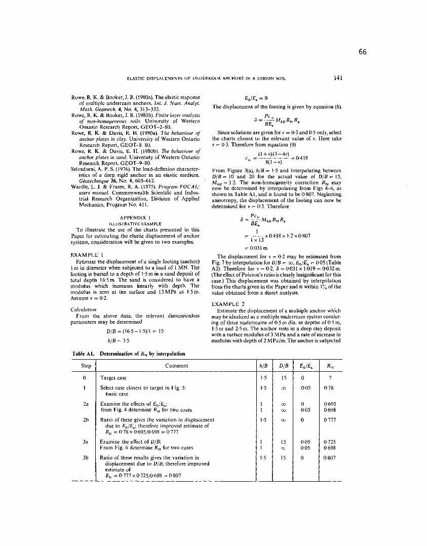
Step Comment h/B D/B Eo/E. RN
0 Target case 1.5 15 0 ?
I Select case closest to target in Fig. 5: 1.5 00 0.05 0.78basic case
2a Examine the effects of Eo/ E.; I 00 0 0.695from Fig. 4 determine RN for two cases I 00 0,05 0,698
2b Ratio of these gives the variation in displacement 1.5 00 0 0.777due to Eo/E.; therefore improved estimate ofRN = 0,78 x 0.695/0'698 = 0,777
3a Examine the effectof D/B; 1 15 0,05 0.725From Fig. 6 determine RN for two cases 1 00 0,05 0.698
3b Ratio of these results gives the variation in 1.5 15 ° 0.807displacement due to D/B; therefore improvedestimate of
RN = 0.777 x 0'725/0.698 = 0,807
ELASTIC DISPLACEMENTS OF UNDERREAM ANCHORS IN A GIBSON SOIL 141
Rowe, R. K. & Booker, J. R. (1980a). The elastic responseof multiple underream anchors. Int. J. Num. Analyt.Meth. Geomech. 4, No.4, 313-332.
Rowe, R. K. & Booker, J. R. (1980b). Fillite layer alia lysisof non-homogeneous soils. University of WesternOntario Research Report, GEOT-2-80.
Rowe, R. K. & Davis, E. H. (1980a). The behaviour ofanchor plates in clay. University of Western OntarioResearch Report, G EOT -8-80.
Rowe, R. K. & Davis, E. H. (I 980b). TIle behaviour ofallchor plates ill salld. University of Western OntarioResearch Report, G EOT -9-80.
Selvadurai, A. P. S. (1976). The load-deflexion character-istics of a deep rigid anchor in an elastic medium.Geotechnique 26, No.4, 603-612.
Wardle, L. J. & Fraser, R. A. (1975). Program FOCAL:users manual. Commonwealth Scientific and Indus-trial Research Organization, Division of AppliedMechanics, Program No. 411.
APPENDIX IILLUSTRATIVEEXAMPLE
To illustrate the use of the charts presented in thisPaper for estimating the elastic displacement of anchorsystems, consideration will be given to two examples.
EXAMPLE IEstimate the displacement of a single footing (anchor)
1 m in diameter when subjected to a load of I MN. Thefooting is buried to a depth of 1'5 m in a sand deposit oftotal depth 16'5m. The sand is considered to have amodulus which increases linearly with depth. Themodulus is zero at the surface and 13MPa at 1.5m.Assume v = 0.2.
C a/culation
From the above data, the relevant dimensionlessparameters may be determined
D/B = (16'5-1'5)/1 = 15
h/B = 1.5
Table Ai. Determination of RN by interpolation
Eo/E. = 0
The displacement of the footing is given by equation (8~
Pc",,,= .--MhORN R.BE.
Since solutions are given for v = 0.3 and 0,5 only, select
the charts closest to the relevant value of v. Here takev = 0.3. Therefore from equation (9)
(l+v)(3-4v)c . = '--'--- = 0-418oc 8(I-v)
From Figure 3(a), h/B = 1.5 and interpolating betweenD/B = 10 and 20 for the actual value of D/B = 15,Moo = 1.2. The non-homogeneity correction RN maynow be determined by interpolating from Figs 4-6, asshown in Table AI, and is found to be 0,807. Neglectinganisotropy, the displacement of the footing can now bedetermined for v = O'3. Therefore
Pc",,,= -MhORNR.BE.
I= '._.n X0-418 x 1.2 x 0'807
1 x 13
= 0.031 m
The displacement for v = 0.2 may be estimated fromFig. 7 by interpolation for D/B = 00,Eo/E. = 0,05(TableA2). Therefore for v = O'2,
"= 0.031 x 1'019 = 0'032 m.
(The effect of Poisson's ratio is clearly insignificant for thiscase.) This displacement was obtained by interpolationfrom the charts given in the Paper and is within 1% of thevalue obtained from a direct analysis.
EXAMPLE 2
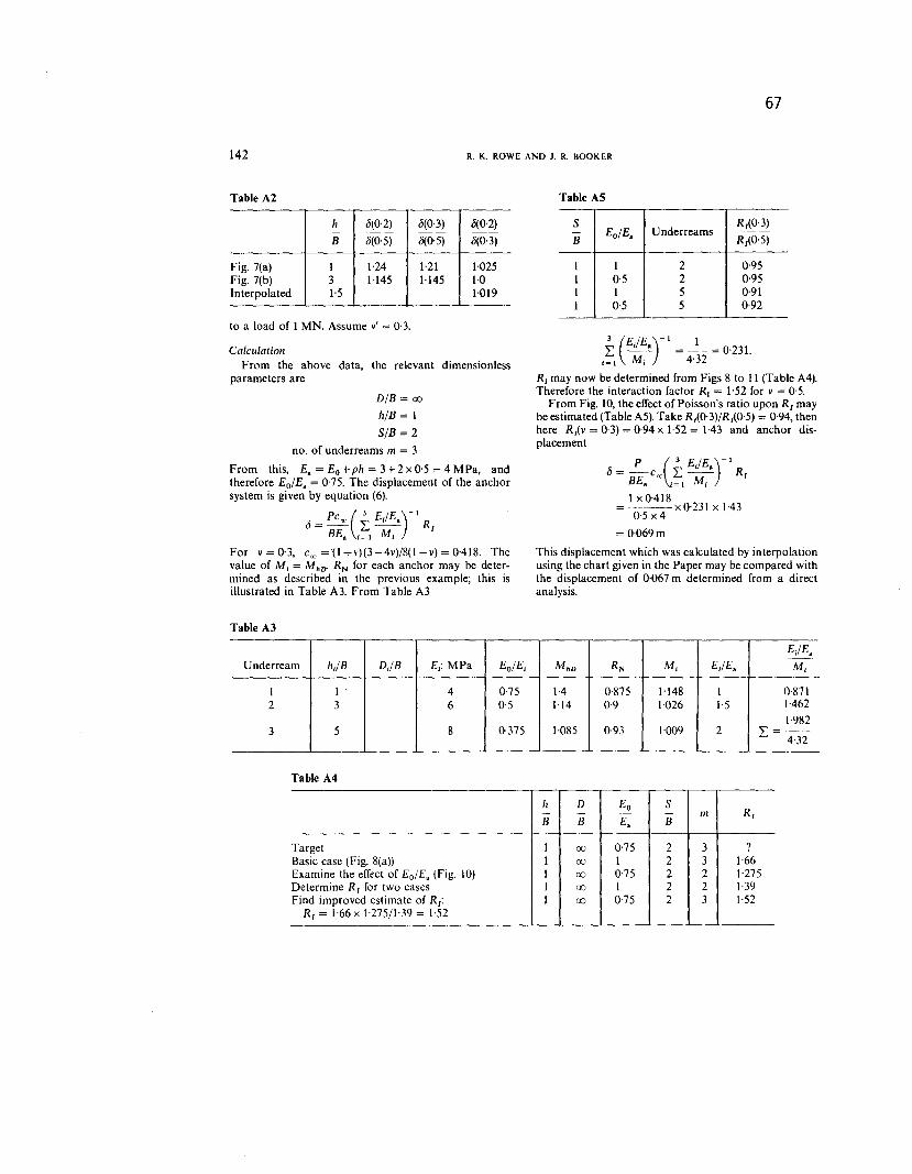
Estimate the displacement of a multiple anchor whichmay be idealized as a multiple underream system consist-ing of three underreams of 0,5 m dia. at depths of 0,5 m,1.5 m and 2'5 m. The anchor rests in a deep clay depositwith a surface modulus of 3 MPa and a rate of increase inmodulus with depth of2 MPa/m. The anchor is subjected
66
h .5(0'2) .5(0'3) .5(0'2)-B .5(0'5) <5{0'5) .5(0.3)
Target \ OCJ 0,75 2 3 ?Basic case (Fig. 8(a)) \ OCJ \ 2 3 1.66Examine the effect of Eo/E. (Fig. 10) \ OCJ 0,75 2 2 1.275Determine RI for two cases \ OCJ \ 2 2 \.39Find improved estimate of Rf: 1 OCJ 0.75 2 3 1.52
RI = \'66x \-275/\'39 = \.52
142
67
R. K. ROWE AND J. R. BOOKER
Table A2
to a load of 1 MN. Assume v' = 0,3.
CalculationFrom the above data, the relevant dimensionless
parameters are
D/B = OCJ
h/B = 1
SIB = 2
no. of underreams m = 3
From this, E.=Eo+ph=3+2xO'5=4MPa, andtherefore Eo/E. = 0.75. The displacement of the anchorsystem is given by equation (6).
PC~ (3 E;/E. )
-1.5=- L-- Rf
BE. j=1 Mj
For v = 0'3, C", ='(1 + v)(3 -4v)/8(l-v) = OAI8. Thevalue of Mj = MhIJ-RN for each anchor may be deter-mined as described in the previous example; this isillustrated in Table A3. From Table A3
Table A3
Table AS
3
(EIE )- 1 1L ~ =~=0'231.
i= 1Mj 432
Rj may now be determined from Figs 8 to 11 (Table A4).
Therefore the interaction factor RI = 1'52 for v = 0,5.
From Fig. 10, the effect of Poisson's ratio upon Rf maybe estimated (Table A5). Take RAO' 3)/RlO'5) = 0,94, thenhere Rf(V = 0'3) =
0,94 x 1.52= 1.43 and anchor dis-
placement
p
(3 EIE )- 1
.5=-coc. L~ RfBE. j=1 Mj
I xO.418=---xO'23\ x \A30,5 x 4
= 0,069 m
This displacement which was calculated by interpolationusing the chart given in the Paper may be compared withthe displacement of 0,067 m determined from a directanalysis.


![[1] 1 2 5 6 15 a 15 a Q) ¥33, ¥33, 000. - 000. - 000. - 15 14 29 04 51 16 53 53 00 17 50 56 08 50 00 40 15 46 09 18 00 09 35 141 141 141 141 141 141 141 141 141 141 141 141 54 49](https://static.documents.pub/doc/80x56/5f09a6d27e708231d427dc4e/1-1-2-5-6-15-a-15-a-q-33-33-000-000-000-15-14-29-04-51-16-53-53.jpg)


