32
HYDRAULICS BRANCH OFFICIAL FILE COPY THEN BORROWED RETURN PROMPTLY s y- 3.. I PAP-537 Aeration in Jets and High Ve by H. T. Falvey D. A. Ervine 1988

HYDRAULICS BRANCH OFFICIAL FILE COPY
THEN BORROWED RETURN PROMPTLY
s
y-
3..
I
PAP-537
Aeration in Jets and High Ve
by
H. T. Falvey
D. A. Ervine
1988

/cl/l I_'
AERATION IN JETS AND HIGH VELOCITY FLOWS
HENRY T. FALVEY,1 M. ASCE D. ALAN ERVINE,2 M. ICE, M. IWES
ABSTRACT
Air entrainment in hydraulic structures is a complicated process involving several mechanisms. Four cases of air entrainment are considered with respect to the mechanism involved, scale effects, inception conditions, quantities of air entrained, and diffusion and transport of the entrained air bubbles. These cases are free surface aeration in jets, free surface aeration in chutes, plunge point entrainment, and hydraulic jump entrainment. The importance of the scale of the turbulence is emphasized.
INTRODUCTION
The performance of many hydraulic structures is modified by the process of air entrainment. The air is entrained into the flow in the form of air bubbles by the action of turbulence at the air-water interface. Once entrained into r the flow, air bubbles are diffused across the flow stream by the process of momentum transfer. For bounded flows, the diffusion process is influenced by the buoyancy of the air bubbles which causes them to rise and pass out of the flow. This air removal is called detrainment. For unbounded flows (free jets), buoyancy does not play a role in the diffusion process.
In addition to being diffused across the flow, air is also transported with the flow. Some of the air is transported as bubbles and some of the air is transported in the air-water interface. The significance of these different means of transport will be considered later.
In some hydraulic structures, aeration is a benefit. For example, the reduction of cavitation damage, the priming of siphons (where air entrainment is essential), the oxygen enrichment of water by hydraulic jumps and plunging jets, and the reduction in impact pressures of impinging jet spillways.
'Hydraulic Consultant, PO Box 4, Conifer, CO 80433
2Professor, Department of Civil Engineering, Rankine Building, The University, Glasgow, Scotland, G12 8LT
1 Falvey/Ervine

In some hydraulic structures air entrainment is a distinct disadvantage. In conduits, for example, air pocket formation often leads to damaging blowback, reduction in discharge capacity, and unsteady flows. The entrainment of too much air in the flow can also lead to supersaturation of the water which is damaging to fish.
To investigate the beneficial or detrimental effects of air entrainment, physical model studies are often used. However, simulating the air entrainment and detrainment processes with physical models is very difficult because it is almost impossible to scale accurately the parameters which influence the entrainment at the air-water interface. In addition, the turbulence scales which influence the range of bubble sizes produced within the flow are also difficult to simulate in a physical model.
In any case, it is important to have a good understanding of the entrainment, transport, and air release mechanisms so that the results of physical models can be interpreted for prototype behavior. In addition, the understanding will insure that mathematical models are based on correct assumptions.
It is generally assumed that all cases of air entrainment are similar. However, this assumption is not true. To illustrate some of the different types of air entrainment and the significant mechanisms which influence each type, this presentation will consider four typical aeration situations, figure 1.
The first two cases represent a mechanism in which small scale turbulence is important. The last two cases represent a mechanism in which large scale turbulence is important for air entrainment. The first case of each pair presents the fundamental mechanism of air entrainment. The second case of each pair shows how these fundamentals are influenced by other parameters.
In each of these cases the mechanisms of entrainment, scale effects, inception conditions, quantities of air entrained, diffusion and transport of air bubbles will be explored.
2 Falvey/Ervine

A
(a) Free surface aeration in jets
Boundary Layer emit of
EnLrninmenL
Aereted Flow
(b) Free surface aeration in chutes
EnErained Air RecirculaEing
Flow
(c) Plunge point entrainment
Rol 1 Ai- 9--1
(d) Hydraulic jump entrainment
Figure 1. Typical Aeration Situations
AERATION IN FREE JETS IN THE ATMOSPHERE.
Mechanism of Entrainment
Observations of turbulent free jets in the atmosphere reveal that the jet is surrounded by many small drops of water. Since these drops obey the same trajectory law of particles that the main body of the jet obeys, the drops do not fall back into the body of the jet. In fact, for almost horizontally discharging jets, it is impossible to distinguish which is up and which is down from a close up photograph of a section of the jet_ Thus it can be reasoned
3 Falvey/Ervine

that the migration of the bubbles to the surface by buoyancy will not occur in free jets.
Another important factor influencing jets in the atmosphere is that, ignoring air resistance, the velocity gradient across the jet becomes negligible within a distance equivalent to several jet diameters. Since a velocity gradient is needed to generate turbulence, turbulence will not be generated within the core of an atmospheric jet. Thus, the scale of the eddies on the interior of a free jet will become increasing smaller in the downstream direction. Although this has not been studied, it is probably the dispersion of the eddies to both air-water interfaces that is responsible for the air entrainment which is observed in the upper nappe at aerators. This entrainment occurs even when the upstream boundary layer has not reached the air-water interface.
The lack of turbulence on the core of the jet and the lack of buoyancy both indicate that bubble motion within the core of the jet is not a significant factor in the air entrainment process of jets. In fact, there is no mechanism to cause bubbles to move toward the axis of the jet.
At the air-water interface another effect is taking place. In this zone, because of the free fall condition, the velocity fluctuations which existed near the boundary of the jet at its beginning, persist throughout the length of fall of the jet. In order to conserve energy, it can be inferred that the eddies should grow as the square root of the fall distance. Davies [5] has shown that this hypothesis is true. He found that the jet eddy lengths vary in the downstream direction as;
1' = Ke IL (1)
where Ke = a constant L = distance along centerline of jet trajectory.
The eddies at the air-water interface cause the surface to randomly bulge both outward and inward. If the turbulent energy is large enough and the eddy is of the proper size range, either a drop of water or an air bubble will be formed, figure 2. The relationships that govern the formation of drops and air bubbles will be considered shortly.
a V_ -1... /T:,---=--

Water Droplets
0 1/2 (~v2
. R
A
6
O
A I r Bubbles IdeaIized Free Surface
Figure 2. Distortion of the Air-water Interface by an Eddy
The authors have proposed [8], following work by Hunt [13] and Sene [25], that a crude balance for the inception of free surface aeration is given by
1/2 (v)2 > 2a /(}1 R) (2)
where R = radius of curvature of the surface disturbances v = root-mean-square value of the normal velocity fluctuations a = interfacial surface tension µ = density of water.
Solving this inequality for v, using water properties at 10° C and a bubble diameter of 5 mm, give
v > 0.24 m/s (3)
as the criterion for the entrainment of bubbles at a free surface. This should also be the criterion for the creation of drops of water or spray at the air-water interface. According to this theory, both bubbles and spray are formed simultaneously.
In terms of the mean water velocity, the criterion is
U > 0.24 /(v/U) = 0.24 /Tu (4)
Thus, if the turbulent intensity at the air-water interface is about 4-percent, the minimum flow velocity required to entrain air is 6 m/s.
These relationships, equations 3 and 4, are not strictly accurate because the inequality is based upon the total kinetic energy of the turbulence. For entrainment, the
5 Falvey/Ervine

critical kinetic energy is the energy contained in the range of air bubble sizes which are entrained.
To illustrate this very important point, three cases are considered: a prototype, a 1:10 scale model and a 1:20 scale model. It is assumed that each case could entrain bubbles in the 1 to 10 mm diameter range. However, before these three cases can be analyzed, the turbulence spectrum must first be considered.
Two methods are used to describe the turbulence of the flow; single point observations and correlations between multiple points. The more common method uses measurements of velocity fluctuations at one point in the flow. If care is taken to determine the fluctuations in the three orthogonal flow directions, an accurate measure of the turbulent intensity can be obtained. Here the turbulent intensity is defined in terms of the statistical quantities which describe the random fluctuations. For instance, the turbulent intensity in the mean flow direction is defined as the root-mean-square value of the fluctuations in the flow direction divided by the mean velocity.
f(u' )2 Tu = --------- ( 5 )
U
where u' = velocity fluctuation in flow direction U = mean flow velocity
In the remainder of this paper, the following notation will be used
U = d(u' )2 (6)
The transverse, w, and normal, V. components of the fluctuating velocity are defined similarly.
The turbulent fluctuation of the flow is the vector sum of these three components, or
q = f (u2 + V2 + w2 ) ( 7 )
where u, v, w = root-mean-square value of the velocity fluctuations in the three orthogonal directions which are tangent to streamline, normal to streamline, and transverse to streamline, respectively.
The kinetic energy per unit mass of the flow is given by
Ek = q2 /2 RM
6 Falvey/Ervine

For homogeneous turbulence, the intensity of each of the orthogonal turbulent components are equal, giving
Ek = 3/2 u2 (9)
The measurements made at one location in the flow give information about the intensity of the turbulence, but they do not indicate the size of the eddies that cause the turbulence. To learn about the size of the eddies it is necessary to form correlations between a fixed point in the flow and other locations in the flow. The Fourier transform of the correlations results in the length spectrum of the turbulent eddies.
The spectrum of turbulent eddy sizes has three regions; a production region, an inertial subrange, and a dissipation range. The production of turbulent energy takes place at small wave numbers, that is, at large eddy sizes. In the inertial subrange, no energy is added to the eddies and no energy is removed. It is "much like a cascade of waterfalls without any springs or drains", (26]. Finally, the dissipation range represents the smallest values of eddies down to the Kolmogorov micro scale. The extent of the dissipation range is determined by the Reynolds number. Increasing Reynolds numbers extend the range to higher values of the wave number, that is, to smaller eddies.
The three ranges, relative to the dimensionless eddy sizes are as follows
Dimensionless Eddy Sizes
Production 0 - 100 Inertial Subrange 100 - Re/10 000 Dissipation Re/10 000 - (m3 /E) 1 i4
where m = viscosity of the water E = dissipation rate per unit mass
Re = Reynolds Number of the eddy
The area under the spectrum is equal to the kinetic energy of the turbulence per unit mass. The energy contained in specified ranges of eddy sizes can be calculated from the area of the spectrum which corresponds to the range of the eddy sizes. The relationship is given by
w n 2
E (wn ) dwn = q2
wnl
where E(wn) = energy intensity 1 = characteristic eddy w„ = wave number
= reciprocal of eddy
7
E (wn )
ld(wn 1) (10)
q2 1 J
length
length
Falvey/Ervine

1:10 Model
9.49
0.48 0.10
7. 3 105
10-100
0.089
1:45 Model
4.47
0.23 0.022
7.6 104
2-20
0.059
Equations for the distribution of the turbulence spectrum, the term in brackets, are given by Tennekes and Lumley [26].
With this brief summary, the spectra for the three cases can now be considered, figure 3. Each spectrum is the quantity of q2 times the term in the brackets. The dimensionless eddy length in figure 3 is the quantity wl.
:N
a') V
E o.o1 z
a 0.001
CD —
W
6 ~e#
)e Adel Adel
0.1 1 10 100 1000 Dimensionless Eddy Length
Figure 3. Length Spectrum of a Turbulent Flow
Using Froude similitude, the significant flow properties of the three cases are as follows;
Prototype
Mean Velocity, U 30 m/s Normal Velocity, u (Tu = 5.0-percent) 1.50 m/s Eddy Length, l' 1 m Reynolds Number, Re 2.3 107 Range of the
Dimensionless Eddies 100-1000 Turbulent Energy in
Range of Eddies 0.187 Nm/Kg (See figure 2)
8 Falvey/Ervine

From the criteria for entrainment, the kinetic energy of homogeneous turbulence (in the proper range of eddy sizes) is given by
(Ek) critical > (3/2)(0.24)2 = 0.086 Nm/Kg (11)
It can be seen that the 1:45 scale model will not entrain air. The ability of the 1:10 model to entrain air is marginal because the kinetic energy of the turbulence is low in the range of eddy sizes which correspond to the range of bubbles which could be entrained. However, the prototype will entrain air.
If the turbulent energy in the range of bubble sizes had not been considered, an erroneous conclusion might have been reached. The order of magnitude estimate of the turbulent intensity required for entrainment was given in equation 3 as 0.24 m/s. Since the normal velocity for each of the two models is greater than or about equal to 0.24 m/s, air entrainment could have been predicted for both of them. This does not mean that the basic derivation of equation 3 is incorrect. The error is in using the mean statistics of the normal fluctuation as an estimate for the fluctuations which entrain air.
Scale Effects
The simulation of the air entrainment should be possible with Froude scale models if care is exercised to reproduce the turbulence intensity of the prototype in the model. In addition, the model should be large enough so surface tension effects are small. Of the two, simulation of the turbulence intensity appears to be the more important.
Pinto [19] studied both surface tension and turbulence effects for the Foz do Areia spillway. In his studies, similitude was achieved for Weber Numbers greater than about 500. It was found that the critical value of the Weber Number was a function of discharge with the higher discharges having a smaller critical value. In his study the significant Weber Number was defined as
V dL We = --------- (12)
1(0/u)
The investigation was conducted with four different model scales 1:8, 1:15, 1:30 and 1:50. The flow into the models entered from a sluice gate located a short distance upstream from the aerator. Therefore, the distance for boundary layer development was very short. The 1:8 and 1:15 scale models produced air flow rates which simulated the prototype values for low discharges. However, the simulation at high discharges was poor.
9 Falvey/Ervine

Artificially introducing turbulence into the 1:30 scale model produced an air entrainment versus discharge curve which was very similar in shape to the prototype curve. It could be expected that higher levels of turbulence would have produced even better results.
The effect of artificially induced turbulence in a model on the entrainment rate was also observed in unpublished studies by the Bureau of Reclamation. In these tests a screen was tacked to the ramp of an aerator. The air entrainment doubled as a result of the added turbulence.
These observations cast doubt on the validity of model inves-tigations which are conducted using a sluice gate to control the flow depth immediately upstream of an aerator. In these models the boundary layer is not similar to that in the prototype and the turbulence intensities throughout the body of water are much too low. Sectional model which have a small width to flow depth aspect ratio are also suspect since the side walls generate turbulence which is not to the proper scale.
Pan and Shao [18], studied the effect of the Reynolds Number on the air entrainment in models and prototypes. In their studies it was necessary to have Reynolds Numbers greater than 3.5 * 106 in order to avoid scale effects. In these studies, the surface roughnesses of the boundaries in the model and the prototype were probably comparable.
Quantities of air entrained by a free jet in the atmosphere
It is very difficult to estimate the quantity of air entrained by a free jet in the atmosphere because the air flow is unbounded. However, in the case of flow from an aerator the area under the jet is bounded. Therefore this case will be examined even though the surrounding air pressure under the jet is less than atmospheric.
Estimates of air quantities entrained have been based primarily on physical reasoning or dimensional analysis, and in both cases the estimation of empirical constants has been necessary. The simplest of these assumed that the air entrainment rate is proportional to the length of the jet. Since the eddy length grows as the square root of length, it should be expected that the air entrainment should also be a function of the square root of the length.
Pan et al [17] and Glazov [10], developed equations for the air entrainment rate based upon turbulence considerations. Both of the methods assume that the total quantity of air entrained is equal to the air quantity passing the impact point, figure 4.
10 Falvey/Ervine

ldoterr Surf oce v'
Compoct Jet
Figure 4. Air Entrainment at an Aerator
The development by Pan et al required physical observations from a model to determine the thickness of the air-water layer. Glazov on the other hand, assumes that the thickness of the layer can be calculated from the trajectory equation using first an upward directed value of the turbulent velocity, V, for the profile of the air penetration into the jet and then a downward directed value for the profile of the spread of the jet into the air. The predicted air entrainment rates match most of the values measured by Pinto [19] at Foz do Areia to within 10 - percent. In both of these methods, the formation of air bubbles within the flow is neglected. Instead, the air entrainment is caused by the spatial increase of the eddies which envelopes air and causes it to move at the velocity of the jet.
The turbulent velocity, v, must be known in order to use the method of Glazov. Fortunately, the normal velocity, v, for boundary layer flows scale as the shear velocity U* and is approximately equal to U* near the wall, Blake [3]. Thus,
v = U* = Vo d(f/8) (13)
where U* = shear velocity
t = shear stress on boundary
Using first order approximations for the trajectory equations of Glazov and neglecting the reduced pressure under the nappe, it can be shown that the air flow rate is given by
g X2 tan O qa = ------------ 1(f/8) + V. X d (f / 8 ) (14 )
Vo cosz
where f = Darcy-Weisbach friction factor g = acceleration of gravity
qa = unit air flow rate Vo = mean velocity at station where free jet
begins X = horizontal distance from beginning of free
jet to impact point with flow boundary
11 Falvey/Ervine

It should be noted that Glazov derives an expression for the trajectory of a jet which is subjected to a reduced pressure on one side.
For small slopes, the first term on the right hand side of the equation is negligible. The equation thus reduces to the familiar correlation
qa = Kf Vo L (15)
or R = Kf L / H (16 )
where H = depth of flow at the station where the free jet begins
Kf = d(f/8) .
This simplified form of the equation has been reported by many researchers, [171, [191, [241, in which the value of the coefficient was determined empirically. The value of the coefficient Kf varies widely because the length of the jet, L, is very difficult to measure accurately in either a model or in the prototype. In addition, the length of the jet is not always clearly defined. In some cases, it is the length to the first point of impact of the jet with the boundary. In other cases, it is the distance to the location of maximum pressure on the boundary.
Neither the simplified equation nor the more complicated one work well when the jet length to thickness ratio is greater than about 50. For this value of the ratio, the turbulence in the air-water interface has reached the axis of the jet. Since air is being entrained on the top of the nappe at about the same rate as it is on the bottom, the jet is no longer continuous across its cross section. The condition in which the surface turbulence reaches the axis of the jet is known as the "break up" of the jet.
The effect of the ramp on the turbulence in the jet has not been studied. It is reasonable to expect that the effect of a small ramp on a deep flow (high unit discharges) will be to increase turbulence in the flow. On the other hand, for shallow flow depths over the ramp (low unit discharges), the acceleration of the flow may decrease the turbulence. Systematic studies in this area are needed.
FREE SURFACE AERATION ON CHUTES.
Mechanism of Entrainment
It is accepted that inception of air entrainment on a chute spillway cannot begin until the boundary layer reaches the free surface [15). This implies once again that turbulence is the most significant mechanism in the entrainment process. However, to entrain air, the turbulence levels at the edge of
12 Falvey/Ervine

the boundary layer must be large enough to overcome both surface tension and gravitational effects.
As with free jets in the atmosphere, the turbulence at the air-water interface is made up of various sized eddies. Some of these cause outward bulges of the water surface which can become large enough to produce drops. It has been argued that the return of these drops to the water surface is the cause of air entrainment on chutes [30]. Undoubtedly, the drops can entrain air. However, as was shown with free jets in the atmosphere, drops and bubbles probably form simultaneously, not drops first. The big differences between air entrainment on chutes and in free jets are that for air entrainment on chutes, turbulence is continuously being generated within the body of the flow and that buoyancy is important.
The downward transport of bubbles into the flow requires that the downward turbulent velocity v is greater than the upward bubble rise velocity. The rise velocity of individual bubbles is a function of the bubble diameters, figure 5. In general, the rise velocity of bubbles whose diameters are between 1 and 10 mm in diameter is about 0.3 m/s. Thus, to transport bubbles in this range down into the flow requires that
v> vb = 0.3 m/s (17 )
This criterion considers only inertia and buoyancy ignoring the effects of turbulence and of mutual interference between individual bubbles.
Figure 5. Rise Velocities of Individual Bubbles
In addition to the criterion given by equation 17, the criterion for the generation of bubbles at the surface must also be met, equation 2. In considering these two, it can be stated from equation 2 that air bubbles of large diameter (greater than 10mm) have a high probability of being entrained across the free surface but a small probability of being transported down into the flow. Whereas bubbles which are quite small (less than 1mm) have a small probability of being entrained across the free surface, but once entrained will almost certainly be transported down into the flow. As
13 Falvey/Ervine

a result, bubbles in the range 1 to 10 mm are the ones most commonly found in nature. The bubbles near the air-water surface are of the order of 10 mm whereas, those near the flow boundary are of the order of 1 mm in diameter, (34].
Scale Effects
From the considerations above, the scaling law for entrainment should be given by equation 1 as
1/2 p v2
---------- = constant for model and prototype (18) 20/R
or p U2 R v2
------- --- = constant for model and prototype (19) 4a U2
Since R is the radius of curvature of free surface disturbances and must be proportional to the bubble diameter being entrained, the criterion becomes
1 p U2 Du v2
-8-1
---a----
I U2
-J = constant for model and prototype (20)
The second term is the reciprocal of the Weber number squared and the third term is the turbulence intensity squared.
If the turbulence intensity (v/U), the density of water p, and the surface tension a are identical in the model and the prototype then in order to entrain bubbles of the proper scale in the model,
Um = Up d L (21)
Since larger than prototype velocities are needed to properly simulate the entrained bubbles, a model based on the Froude scale will always entrain less air than the prototype structure.
Scaling is further complicated by the fact that the turbulent energy, in the range of eddy lengths which correspond to the bubble sizes entrained, is significant for air entrainment. Thus, small size models may entrain less air, or possibly entrain no air, if the turbulence energy falls below the critical value in the required range of eddy lengths. This can happen even if the model has the same turbulent intensity as the prototype. In other words, not only is the similarity of turbulent intensities important for simulation, but the distribution of the turbulent energy as a function of the eddy size is also very significant.
14 Falvey/Ervine

The criterion for entrainment can also be written as:
u U2 D Db v ------- -- --- — constant for model and prototype (22)
o D U
where D = the,depth of flow or jet diameter. Db = bubble diameter
The ratio Db/D plays a significant role in the air bubble transport and air release process after entrainment has occurred. For all practical purposes, model and prototype bubble diameters are almost identical. Thus, the relative velocity vector of the bubble will be different in the model and in the prototype, figure 6. Air bubbles will detrain (or be released) relatively more quickly in the model than in the prototype.
UL) Rm
1P Um
Model Prototype
Figure 6. Relative Velocity Vector of Bubbles
At this point it - is useful to consider the non-dimensional numbers required to characterize air entrainment, transport, and detrainment for free surface entrainment on chutes.
It was shown above that entrainment through the free surface is a function of turbulence and surface tension. It is assumed that the turbulent velocity v scales as the shear velocity u* and hence as the mean flow velocity U. This is generally the case when considering the entire energy spectrum. However, small model scales contain relatively less turbulent energy in the range of eddy sizes which correspond to the sizes of entrained bubbles. This implies that the turbulent velocity v needs to be characterized by the Reynolds Number. The surface tension effect in Equation (2) is characterized by the Weber Number.
The transport and detrainment processes within the flow are a function of buoyancy and turbulence intensity. This implies that both Froude and Reynolds numbers need to be simulated.
Thus the quantity of air entrained into the flow must be given by,
(3 = Q. /Qw = f (Fr , We , Re , Pa /p, ks /h) (23)
15 Falvey/Ervine

where Fr = Froude Number V
1(g h)
We = Weber Number V
Re = Reynolds Number V h
m
u = density of water pa = density of air ks = sand grain roughness of surface h = flow depth m = kinematic viscosity V = mean flow velocity
For steep slopes, the Froude Number should be defined as
V Fr= -------------
1(g h cos e)
where e = angle spillway slope makes with horizontal
Exact correlations for the air flow rate require the simulation of all of these dimensionless parameters. Scale models of course are unable to simulate all of these effects simultaneously. Since the entrainment cannot be studied with scale models, experiments are made on air entraining flows in an attempt to discover an equation which relates the various independent parameters.
To date, no correlation contains an explicit relationship with the Reynolds Number. Turbulence effects are usually accounted for implicitly by the inclusion of a bottom slope parameter. For fully developed flow, that is for flow in which the depth and air content do not vary with distance, the body force exerted on the flow prism is exactly balanced by the shear force. It can be shown that
U, 2
sin e = ------- (24) g h
The simpler correlations for the quantity of air entrained include only the Froude Number and the invert slope. More sophisticated versions include the surface tension effect.
These correlations will be discussed in more detail below.
16 Falvey/Ervine

Inception Conditions for free surface aeration on chutes.
The first condition that must be met for the inception of air entrainment with free surface aeration is that the boundary layer has reached the water surface. Many equations have been proposed to define the thickness of the boundary layer. One of the most promising results for the thickness of a spillway boundary layer has been proposed by Wood, Ackers and Loveless [33] in the form,
6/x = 0.0212 (x/Hs)o•11 (x/k) - 0•1 (25)
where x = distance along spillway length. Hs = difference between reservoir elevation and
water surface elevation at point of entrainment.
The next condition to be met is that the turbulence level is large enough relative to the surface tension. This can be expressed as
T° > K * Eo / Fr 2 ( 26 )
where K = a coefficient whose theoretical value is 4.0
Eo = E6tv6s Number for the bubble a
t DO
Fb = Froude Number for the bubble U
g Db
As was shown earlier, this condition requires that
U (m/s) > 0.24/ Tu (27)
for the entrainment of 5 mm diameter bubbles in water.
Quantities of air entrained by free surface aeration on spillwav chutes.
Many authors have searched for correlations which relate the flow parameters to the quantity of entrained air under fully developed aeration. They expressed the amount of entrained air either as a mean air concentration or as the ratio of air flow rate to the water flow rate. These two are related by
C = R / (1+(3) (28)
or 0 = C / (1-C) (29)
where C = mean air concentration in volume air per volume water
(3 = ratio of air flow rate to water flow rate.
17 Falvey/Ervine
The simplest models formed correlations only with the Froude Number. An example of this is the equation by Haindl [11] for the mean air/water flow rate ratio in a spillway chute flow given in the form.
Q = k Fr 2 = k V2 / (g Rh ) ( 30 )
where k = a constant whose value lies between 0.0035 and 0.0104
Rh = hydraulic radius
This equation was modified by Yevjevich and Levin [35] to take the bed roughness into account. They gave the equation in the form
0 = 0.175 Fr 2 n dg Co / Rh 1 /6 ( 31)
where n = Manning's coefficient Co = velocity distribution coefficient whose
value is approximately equal to 1.0
Rao and Kobus [21] produced a similar but simpler relationship for the ratio of air to water flow in the form,
R = 1.35 n Fr3/2 (32)
Volkart [31], proposed an equation based upon a Boussinesq Number in the form
1 C = 1 - ----------------------- (33)
0.02(BW - 0.6)1.5 + 1
where Bw = Boussinesq Number = V/f (g Rh )
Falvey [9] proposed a relationship for the mean air concentration taking into account the influence of surface tension. His equation can be written as
( Eo sin ® )1/2
C = 0.05 Fr - ---------------- (34) 63
This equation is limited to values of mean air concentration between 0.0 and 0.6 and to smooth boundaries.
Obviously, there is still room for others to make their contribution in this area!
Transport of air bubbles in chute flow.
An air bubble in a turbulent chute flow will have four main forces acting on it, namely inertial, drag, buoyancy and turbulent eddy transport forces, figure 7. With fully
is Falvey/Ervine

developed flow, the bubbles move with the flow with very little slip. Thus, the inertial and drag forces can be assumed to be in balance.
buoyancy
Drag I next i o
TurbUlenL Trcnsport
e ~
Figure 7. Forces on an Individual Bubble
Air bubbles, once entrained into the flow, are diffused into the depth of the flow by turbulence which transfers air bubbles from high concentration areas to lower. The bubble motion is resisted in this process by the buoyancy of the air bubbles. If the flow path is long enough, an equilibrium condition is established some distance downstream from the inception point. One way of analyzing the distribution of the air concentration across the depth of the flow is to consider the air-water mixture as a pseudo fluid of variable air concentration.
Rao and Gangadharaiah [20] assumed that the air concentration distribution in the body of the flow can be analyzed by the equation for the transport of a scaler quantity in a turbulent, steady, incompressible and two-dimensional flow. By making appropriate assumptions they derived the transport equation as
dC d dC Vb -
dy dy ----- _ -dy
C e -
dy ---
J + Fd ( 3 5 )
L. J
where e = eddy transport or diffusivity coefficient Fd = driving force, independent of y Vb = rise velocity of bubble
This was solved for the air concentration at the wall. Using several empirically determined coefficients they found a relationship which can be written as
CW = 1.17 C3 • 3 +(1-1.11C2. 19 )3 (4.2*10-4 -0.106 • 5 ) /C6 • 5 (36)
An interesting point from the studies of Rao and Gangakharaiah is that the air concentration at the wall is greater than the mean air concentration if the mean air concentration is less than 0.46! This observation is very significant with respect to the question of how close together aerators need to be placed in order to prevent cavitation damage.
U
19 Falvey/Ervine

PLUNGE POINT AIR ENTRAINMENT
Mechanism of Entrainment
By definition, plunge point entrainment occurs when a high velocity supercritical flow impinges on an ambient or slowly recirculating flow. The upstream flow may be a free atmospheric jet or a wall jet, and in both cases entrained air enters a spreading shear layer where it encounters deceleration and lateral diffusion, figure 8.
The most convincing argument on the mechanism of plunge point entrainment has been proposed by Sene [25] and Thomas [28]. They assumed that there is no free surface aeration in the upstream supercritical flow and that the turbulent eddy velocity component v generates surface disturbances of characteristic height y*, length l' and free surface radius of curvature R, figure 8.
Cryan - p -
~pp~d qJ~ B~6biQ
Figure 8. Plunge Pool Entrainment
Upon entering the receiving water, a recirculating flow is established above the shear layer. The velocity of the recirculating flow is given by
Ur /U = 0.035, (37)
where U = mean velocity in the jet Ur = recirculating flow velocity
The dynamic pressure in the recirculating flow is given by
P = 1/2 (µ Ur ) (38)
where µ = density of water, assuming no air bubbles in this region.
Sene [25] and Thomas [28] argue that a surface tension stress is needed to maintain the concave free surface shape and that the receiving water will attempt to follow the free surface undulations at the point of impact. Air will be entrained
20 Falvey/Ervine

when the receiving water is unable to follow the free jet surface and an air pocket will form.
Thus the criterion for air entrainment would be
2 o/R > 1/2 9 Ur' (39)
This type of entrainment appears to be the dominant mechanism for mean flow velocities less that 10m/s. For jet velocities greater than about 10m/s a continuous layer of air exists between the free jet surface and the receiving water. This layer is sustained by air dragged along in the air boundary layer above the jet.
Scale Effects
In many types of air entraining flows there still remains a question of how to simulate the air entraining mechanism. However, for plunge point models such as drop shafts, siphons, hydraulic jumps, and impinging jets, the question has been answered.
Several authors have argued that the rate of entrainment is dependent on the velocity of the flow at the plunge point and not on the depth or thickness of the flow at that point. The air transport and air release processes are dependent on the bubble rise velocity characterized by the ratio Un/U. Since the bubble rise velocity is almost constant for model and prototype, this process is also dominated by the absolute velocity of the flow. By implication, scale effects in aeration can be described by velocity terms. The corre-lations should thus be in the form
Q = E* f (Fr ) (40)
where E* = scale effect term.
Ervine [6] derived the following aeration scale effect term for impinging jet entrainment in the form
E* = (1 - Um/Uj ) ( 41)
where Um = the minimum velocity to entrain air (1 m/s) UJ = the jet velocity at the impingement point.
Thomas [27] used a more sophisticated analysis for aeration scale effects in hydraulic jumps in the form
E* = (1 - Um /U) 2 / (1 - Um/3U) (42)
Finally, Castelyn, Van Groen and Kolkman [4] working on siphons, as well as Ahmed and Ervine [1] working on drop shafts, produced a scale effect term,
21 Falvey/Ervine

E* = (1 - Um/U) 3 (43)
The value of the minimum entrainment velocity is a function of the turbulent intensity of the flow, figure 9. Exper-imental investigations on various types of flow show that the minimum entrainment velocity is given approximately by
Um = 0.25/Tu (44)
It is clear that a scale model with an impingement velocity less that 1 m/s will produce little or no air entrainment, while a model with plunge point velocity greater that 6 m/s will have negligible aeration scale effects.
4J 10-
E UJ _
C (0g Free SurFoce Aeration
~ E
~6 Air Slot With Ramp w -4J
E ~4 Plunge Point 7 E Entrainment
- C U min= 8.25/Tu
e 0 5 10 l5 20 25 30
Turbulence I nEens i ty . Tu ( 7 )
Figure 9. Minimum Entrainment Velocity
Air entrainment rates in plunge point aeration.
As shown above, the rate of air entrainment is a function of the size of the free surface fluctuations as these characterize the volume of air held in the concave hollows. The velocity at which these undulations approach the plunge point will also be of importance and will of course be related to the mean flow velocity.
For the 2-dimensional case, ignoring surface tension effects, the air flow rate per unit length of the jet's perimeter is given by
qa = f (U Y* ) (45)
The height of the disturbance can be estimated by equating the turbulent dynamic pressure force with the gravity force which gives
1/2 u (v)2 Z p g y* cos © (46)
or y* = (v) 2 / (2g cos (9) (47)
22 Falvey/Ervine
Therefore, the quantity of air entrained by the impinging flow is given by
qa = f[U (v)2 /(2g cos 0)] (48)
or qa = f [ U U2 (v/U) 2 /(2g cos0) ] (49)
Thus, for flow on an incline,
[i = f[ Fr Tut ] (50)
Many investigators have tried to form correlations with the Froude Number. Some have included scale effect terms. However, no one has tried correlating the entrainment with a turbulence term included. This may be a reason for some of the variance in the results obtained by the various inves-tigators.
The two most popular forms of entrainment equations are [1], [4] , [21] , [23] , [27]
[i = Ke Fr 2 (51)
and Q = Ke Fr' (1 - 0.8/V)3 (52)
where Ke = an entrainment coefficient
The 0.8 m/s velocity factor in the latter equation evidently corresponds to a turbulence intensity of about 25 in the model facilities.
Unfortunately, the entrainment coefficient is not a constant. This demonstrates that either the functional relationship is not correct or not all of the parameters which influence the entrainment mechanism are being considered.
For free falling jets which impinge in a pool, the Froude Number is obviously not a significant parameter because gravity does not act to bring the surface disturbances back into the flow. As was shown in the discussion about free jets in the atmosphere, the magnitude of surface disturbances is more related to the square root of the plunge length L than to a gravity term. Ervine and Elsawy [6] produced a relationship for wide rectangular plunging jets in the form
0 = 0.13 d(L/d) (53)
where d = jet thickness
For circular jets, Bin [2] recommends a correlation of the form
Qa = 0.015 (doe V3 IL /sin 8)0.7'5 (54)
It should be noted that neither of these correlations include a term for the intensity of the turbulence in the jet where
23 Falvey/Ervine
it originates. The effect of turbulence is to modify the magnitude of the proportionality coefficient in each equation.
AIR ENTRAINMENT IN A HYDRAULIC JUMP.
echanism of Entrainment
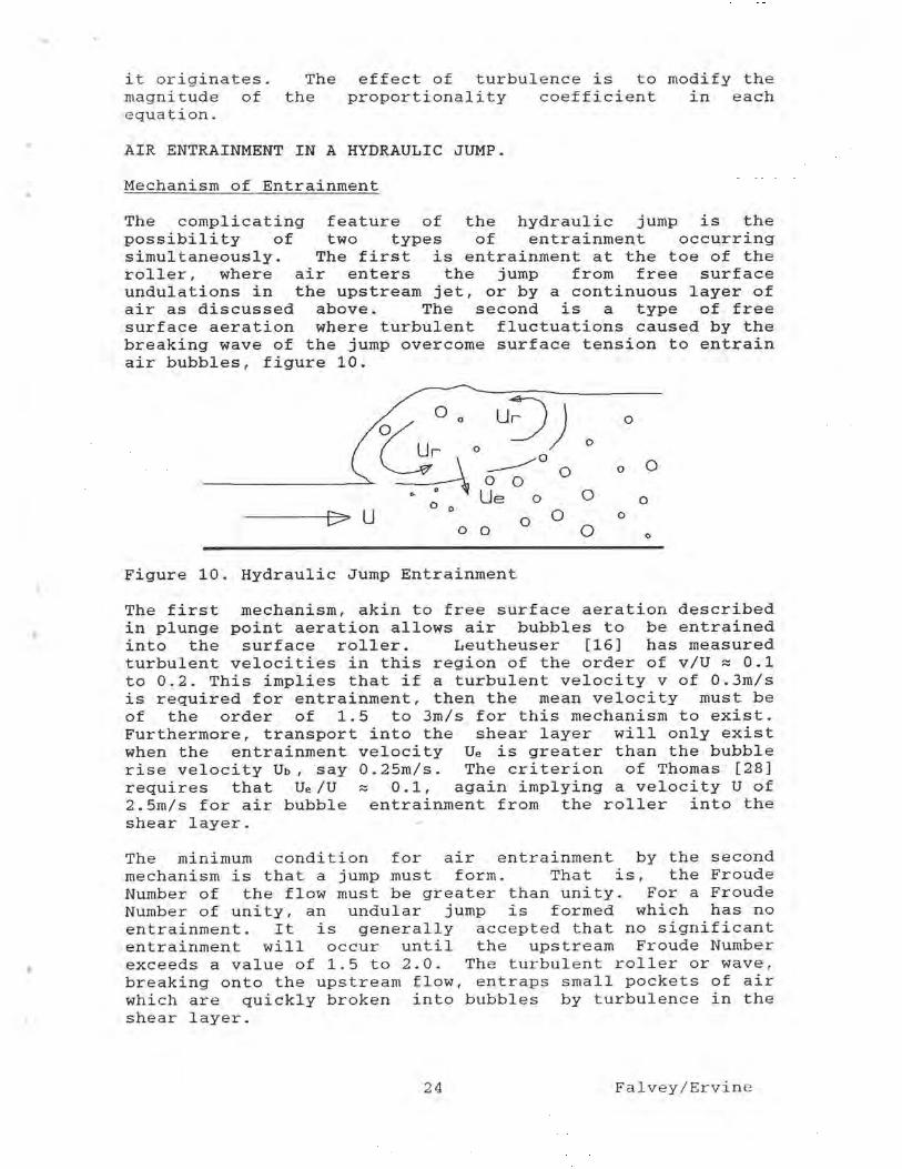
The complicating feature of the hydraulic jump is the possibility of two types of entrainment occurring simultaneously. The first is entrainment at the toe of the roller, where air enters the jump from free surface undulations in the upstream jet, or by a continuous layer of air as discussed above. The second is a type of free surface aeration where turbulent fluctuations caused by the breaking wave of the jump overcome surface tension to entrain air bubbles, figure 10.
;Me]
0 o 1.1 r o
~~r ° o ~~~0
O
lrl O o O :::f~ O p
o 0 0 Ue o o O o ° o O Q a
Figure 10. Hydraulic Jump Entrainment
The first mechanism, akin to free surface aeration described in plunge point aeration allows air bubbles to be entrained into the surface roller. Leutheuser [16] has measured turbulent velocities in this region of the order of v/U = 0.1 to 0.2. This implies that if a turbulent velocity v of 0.3m/s is required for entrainment, then the mean velocity must be of the order of 1.5 to 3m/s for this mechanism to exist. Furthermore, transport into the shear layer will only exist when the entrainment velocity Ue is greater than the bubble rise velocity Ub, say 0.25m/s. The criterion of Thomas [28] requires that Ue/U 0.1, again implying a velocity U of 2.5m/s for air bubble entrainment from the roller into the shear layer.
The minimum condition for air entrainment by the second mechanism is that a jump must form. That is, the Froude Number of the flow must be greater than unity. For a Froude Number of unity, an undular jump is formed which has no entrainment. It is generally accepted that no significant entrainment will occur until the upstream Froude Number exceeds a value of 1.5 to 2.0. The turbulent roller or wave, breaking onto the upstream flow, entraps small pockets of air which are quickly broken into bubbles by turbulence in the shear layer.
24 Falvey/Ervine

Scale Effect
As outlined above, hydraulic jumps in both open and closed conduits have two entrainment mechanisms operating simultaneously. At the toe of the roller the mechanism is that outlined for plunge points, where the rate of entrainment scales as
R = f (Tu2 Fr2) (55)
Along the length of the turbulent roller, Thomas [28) has shown that the rate of entrainment from this source scales as
P = f (Fr - 1) , (56)
at least for Froude Numbers less than 10.
The problem of two mechanisms is further compounded by the sensitivity of hydraulic jump entrainment to the transport capacity of the jump downstream of the shear layer. This point was extensively investigated by Thomas [28] who produced transport scale factors to be applied to the Fr-1 entrainment scaling.
Quantities of air entrained by hydraulic jumps.
Correlations have been obtained for jumps occurring both in open channel flow and in closed conduits. The main correlations of air/water ratios in open conduit hydraulic jumps are,
R = 0.018 (Fr - 1)1.245 (57)
by Rajaratnam [22] and
R = 0.005 Fr (58)
by Renner [23].
Both equations represent the total entrainment into the open conduit jump and do not reflect the transport capacity downstream, which is more important in closed conduit hydraulic jumps.
For closed conduits, Thomas [27] proposed for air transport rates,
(3 = 0.03 E* (Fr - 1) (59)
The value of E* was given earlier and represents the correction for the scale effect.
Kalinski and Robertson [14] proposed the following equation for a circular conduit jump,
0 = 0.0066 (Bw - 1) 1 . 4 . ( 60)
25 Falvey/Ervine

In this equation, the Boussinesq Number is defined at the toe of the hydraulic jump. Therefore, to apply the equation to model or prototype installations, it is necessary to either measure the flow conditions at the toe of the jump or to calculate them using water surface profile computations.
This equation was confirmed by Falvey [9] using prototype data for flows in both circular and rectangular conduits.
The Kalinski and Robertson equation is attractive in its simplicity, but does not differentiate between the two mechanisms of entrainment nor the transport capacity downstream. The fact that the power is 1.4 may reflect the combination of the two scaling criteria.
Others have proposed similar correlations to the Kalinski and Robertson equation, but with different coefficients, [29], [32]. However, an analysis of their data has shown that some of the test results include cases of entrainment due to flow with a free surface. Since the two flows are so dissimilar, the correlations have no meaning.
Air bubble transport downstream of the iump.
The transport of bubbles downstream of a jump in open channel flow is dependent upon the turbulence in the downstream flow. This question was discussed in detail in the section "Free Surface Aeration in Chutes". If the jump entrains more air than the flow can transport, the air will detrain. Otherwise, the air entrained by the jump will be transported with the flow and additional free surface aeration will occur until the equilibrium condition is achieved.
The transport of bubbles in closed conduits is more complicated. For certain combinations of discharge, slope, and pipe roughness, the bubbles will move upstream and pass through the hydraulic jump. As the discharge is increased, a condition is reached in which the bubbles move downstream. However, they tend to rise to the crown of the conduit and collect into large air pockets. These pockets have a larger rise velocity than the small bubbles and thus will move upstream. This condition is called "blow back" and has caused severe damage to some structures [9]. Finally, if the discharge is large enough, both the bubbles and the pockets will move downstream.
Efforts have been made to quantify the motion of the bubbles and the air pockets [7], [9], [14]. As was shown earlier, the bubble motion is dependent upon the turbulence intensity, buoyancy, and surface tension effects. Therefore, any correlations which use only Froude scaling will probably be incorrect. In addition, data taken from small scale models will not be correct because of surface tension effects. At the present time, the motion of air bubbles in a closed conduit is an open subject.
26 Falvey/Ervine

CONCLUSIONS
Four different cases of air entraining flows have been considered in some detail. In each of the cases it was shown that different mechanisms influence the quantity of air which is entrained. Scaling laws which are applicable for one case were completely inapplicable for another. Therefore, great care needs to be exercised in choosing parameters with which to form correlations.
The traditional methods of dimensional analysis which have been so successfully used in the past are probably misleading when applied to air entraining flows. Instead a much more careful examination of the entrainment mechanism must be considered. For example, the distribution of the turbulent energy as a function of eddy size has generally been completely ignored. However, this parameter may be one of the most important considerations in the entrainment process. Trying to simulate this function by adherence to Froude similitude laws simply will not work. For that matter, Reynolds similitude also will not be effective unless the relative roughness of the surfaces are also considered.
Prior to 1900 there were many equations to predict the friction factors in open and closed conduits. All of these equations were superceded by a unified theory of boundary resistance which developed from the boundary layer concept of Prandtl. By analogy, we have a pre 1900 state of knowledge about air entraining flows. This will not change until more detail is paid to the role of turbulence in the air entraining process.
Appendix A. References
1. Ahmed, A.A., Ervine, D.A., McKeogh, E.J., "The Process of Aeration in Closed Conduit Hydraulic Structures", International Association for Hydraulic Research, Symposium on Scale Effects in Modelling Hydraulic Structures, Esslingen Germany, Paper 4.13, Sep 3-6, 1984.
2. Bin, A.K., "Air Entrainment by Plunging Liquid Jets", International Association for Hydraulic Research, Symposium on Scale Effects in Modelling Hydraulic Structures, Esslingen Germany, Paper 5.5, Sep 3-6, 1984.
3.Blake, W.K.," Turbulent Boundary-Layer Wall-Pressure Fluctuations on Smooth and Rough Walls", Journal of Fluid Mechanics, Vol. 44, Part 4, pp637-660, 1970
4. Casteleyn, J.A., Van Groen, D., Kolkman, D.A., "Air Entrainment in Siphons: Results of Tests in Two Scale Models and an Attempt at Extrapolation", International Association for Hydraulic Research, Proceedings of the XVII Congress, Baden Baden, Germany, Nov, 1977
27 Falvey/Ervine

5. Davies, J.T., Turbulence Phenomena, Academic Press, New York and London, 1972.
6. Ervine, D.A., Elsawy, E.M., "The Effect of a Falling Nappe on River Aeration", International Association for Hydraulic Research, Proceedings of the XVI Congress, Sao Paulo, Brazil, Paper C45, Jul, 1975
7. Ervine, D.A., Himmo, S.K., "Modelling the Behavior of Air Pockets in Closed Conduit Hydraulic Systems", International Association for Hydraulic Research, Symposium on Scale Effects in Modelling Hydraulic Structures, Esslingen Germany, Paper 4.15, Sep 3-6, 1984.
8. Ervine, D.A., Falvey, H.T., "Behavior of Turbulent Water Jets in the Atmosphere and in Plunge Pools", Proceedings of the Institution of Civil Engineers, Part 2, Vol 83, pp 295-314, Mar, 1987
9. Falvey, H.T., "Air-Water Flow in Hydraulic Structures", United States Department of the Interior, Bureau of Reclamation, Engineering Monograph 41, Dec, 1980.
10. Glazov, A.I., "Calculation of Air-Capturing Ability of a Flow Behind an Aerator Ledge", Hydrotechnical Construction, Vol 18, No 11, pp 554- 558, 1984
11. Haindl, K., "Aeration at Hydraulic Structures", Developments in Hydraulic Engineering - 2, (Ed. Novak, P.) Elsevier Applied Science Publishers, London and New York, 1984
12. Hinze, J.O., Turbulence, McGraw-Hill, New York, 1959
13. Hunt, J.C.R., "Turbulent Structure and Turbulent Diffusion Near Gas Liquid Interfaces", Gas Transfer at Water Surfaces, pp 67-82, D.Reidel Publishing Co., 1984.
14. Kalinski, A.A., Robertson, J.M., "Closed Conduit Flow-Entrainment of Air in Flowing Water, Transactions of the American Society of Civil Engineers, Vol 108, pp 1435-1516, 1943
15. Keller, R.J., Rastogi, A.K., "Design Chart for Predicting Critical Point on Spillways", American Society of Civil Engineers, Journal of the Hydraulics Division, Vol 103, No. 12., pp 1417-1429, Sep 1977.
16. Leutheuser, H.J., Resch, F.J., Alernu, S.,"Water Quality Enhancement Through Hydraulic Aeration", International Association for Hydraulic Research, XVst Congress, Istanbul, Turkey, Sep, 1973.
17. Pan, S., Shao, Y., Shi, Q., Dong, X., "Self-Aeration Capacity of a WAter Jet Over an Aeration Ramp", Journal of Hydraulic Engineering, No. 5, pp 13-22, Beijing, China, 1980.
28 Falvey/Ervine

United States Department of the Interior, Bureau of Reclamation Translation No. 1868, Book No. 12,455, Paper No. 2, 1983
18. Pan, S., Shao, Y., "Scale Effects in Modelling Air Demand by a Ramp Slot", International Association for Hydraulic Research, Symposium on Scale Effects in Modelling Hydraulic Structures, Esslingen Germany, Paper 4.7, Sep 3-6, 1984.
19. Pinto, N., Neidert, S.H., "Model-Prototype Conformity in Aerated Spillway Flow", B.H.R.A., International Conference on Hydraulic Modelling, Coventry, England, Paper E6, pp 273-284, Sep, 1982
20. Rao, N.S., Gangadharaiah, T., "Self-Aerated Flow Characteristics in Wall Region", American Society of Civil Engineers, Journal of the Hydraulics Division, Vol 97, No. 9., Sep 1971.
21. Rao, N.S.L., Kobus, H.E., Characteristics of Self Aerated Surface Flows, Water and Wastewater, Current Research and Practice, Vol 10, Erich Schmidt Verlag, Berlin, 1973
22. Rajaratnam, N., "Hydraulic Jumps" Advances in Hydroscience, Academic Press, New York, Vol 4, pp 255-262, 1967
23. Renner, J., "Air Entrainment in Surface Rollers", B.H.R.A., Symposium of Design and Operation of Siphons and Siphon Spillways, London, 1975
24. Rutschmann, P., Volkart, P. "Spillway Chute Aeration", International Water and Power Construction, Vol 40, No. 1, pp 10-15, Jan, 1988
25. Sene, R.J., "Aspects of Bubbly Two-Phase Flow", PhD Thesis, Trinity College, Cambridge, 1984.
26. Tennekes, H., Lumley, J.L., A First Course in Turbulence, The MIT Press, Cambridge, Ma., 300 pp, 1972.
27. Thomas, N.H., "Air Demand Distortion in Hydraulic Models", B.H.R.A., International Conference on Hydraulic Modelling, Coventry, England, Paper E5, pp 253-272, Sep, 1982
28. Thomas, N.H., "Entrapment and Transport of Bubbles by Transient Large Eddies in Multiphase Turbulent Shear Flows, B.H.R.A., International Conference on Physical Modelling on Multi-Phase Flow, Coventry England, pp 169-184, Apr, 1983
29. United States Corps of Engineers, "Air Demand - Regulated Outlet Works", Hydraulics Design Criteria, Chart 050-1
30. Volkart, P.U., "The Mechanism of Air Bubble Entrainment in Self-Aerated Flow", International Journal of Multiphase Flow, Vol 6, pp 411-423, 1980.
29 Falvey/Ervine

31. Volkart, P.U., "Transition from Aerated Supercritical to Subcritical Flow and Associated Bubble De-aeration", International Association for Hydraulic Research, 21st Congress, Melbourne, Australia, 19-23 August, 1985.
32. Wisner, P., "Role of the Froude Number in the Study of Air Entrainment", International Association for Hydraulic Research, 11th Congress, Leningrad, USSR, Paper 1.15, 1965
33. Wood, I.R., Ackers, P., Loveless, J., "General Method for Critical Point on Spillways", American Society of Civil Engineers, Journal of the Hydraulics Division, Vol 109, No. 2., Feb 1983.
34. Wood, I.R., "Air Water Flows", Keynote Address, International Association for Hydraulic Research, 21st Congress, Melbourne, Australia, 19-23 August, 1985.
35. Yevjevich, V., Levin, L., "Entrainment of Air in Flowing Water and Technical Problems Connected With It", International Association for Hydraulic Research, Proceedings, pp 439-454, Minneapolis, MN, 1953.
Appendix B. Glossary
C = mean air concentration in volume air per volume water
Co = velocity distribution coefficient whose value is approximately equal to 1.0
D = the depth of flow or jet diameter. Db = bubble diameter d = jet thickness E = energy intensity e = eddy diffusivity of the concentration f = Darcy-Weisbach friction factor g = acceleration of gravity H = depth of flow at the station where the free jet
begins Hs = difference between reservoir elevation and water
surface elevation at point of entrainment. h = flow depth Ke = a constant K = a coefficient whose theoretical value is 4.0 Kf = 1(f/8) k = a constant whose value lies between 0.0035 and
0.0104 ks = sand grain roughness of surface L = distance along centerline of jet trajectory. 1 = characteristic eddy length 1' = eddy length m = kinematic viscosity of water n = Manning's coefficient R = radius of curvature of the surface disturbances Rb = hydraulic radius q = turbulent velocity vector
30 Falvey/Ervine

qa = unit air flow rate t = shear stress on boundary U = mean flow velocity Ub = recirculating flow velocity U* = shear velocity
= f(t/u) u, = longitudinal velocity fluctuation Vb = rise velocity of the bubble in turbulent flow Vo = mean velocity at station where free jet begins v' = normal velocity fluctuation v = root-mean-square value of the normal velocity
fluctuations w = wave number X = horizontal distance from beginning of free jet to
impact point with flow boundary x = distance along spillway length. y = distance perpendicular to the bed. yr = depth of roller above entrainment point
Bw = Boussinesq Number V
d ( g Rh)
Eo = Eotvos Number for the bubble 6
C Db a
Fb = Froude Number for the bubble V
g Db
Fr = Froude Number V
------------- d(g h cos ©)
We = Weber Number V
Re = Reynolds Number V h
m
R = ratio of air flow rate to water flow rate. E = dissipation rate per unit mass a = interfacial surface tension u = density of water }la = density of air O = angle spillway slope makes with horizontal
31 Falvey/Ervine


