47
Theodolite: Introduction
| Date post: | 15-Jul-2015 |
| Category: |
Engineering |
| Upload: | rajendra-prasad |
| View: | 1,418 times |
| Download: | 5 times |

Theodolite: Introduction
Theodolite is used to measure the horizontal and vertical angles.
when the objects are at a considerable distance or situated at a considerable elevation or depression ,it becomes necessary to measure horizontal and vertical angles more precisely. So these measurements are taken by an instrument known as a theodolite.
Theodolite is more precise than magnetic compass.
Magnetic compass measures the angle up to as accuracy of 30’. However a vernier theodolite measures the angles up to and accuracy of 10’’, 20”.
There are variety of theodolites

The Theodolite is a most accurate surveyinginstrument mainly used for :
• Measuring horizontal and vertical angles.
• Locating points on a line.
• Prolonging survey lines.
• Finding difference of level.
• Setting out grades
• Ranging curves
• Tacheometric Survey

CLASSIFICATION OF THEODOLITES
Theodolites may be classified as ;
A.
i) Transit Theodolite.
ii) Non Transit Theodolite.
B.
i) Vernier Theodolites.
ii) Micrometer Theodolites.

A. Transit Theodolite: A theodolite is called a transit
theodolite when its telescope can be transited i.e revolved
through a complete revolution about its horizontal axis in the
vertical plane,
Non-Transit type, the telescope cannot be transited. They are
inferior in utility and have now become obsolete.
B. Vernier Theodolite: For reading the graduated circle if
verniers are used ,the theodolite is called as a Vernier
Theodolite.
Whereas, if a micrometer is provided to read the graduated
circle the same is called as a Micrometer Theodolite.
Vernier type theodolites are commonly used .

Types of Theodolite
There are different types of theodolite available. It may be classified into three broad categories.
Vernier or Transit Theodolite
Digital Theodolite
Total Station

Digital Theodolite
This type of theodolite provides the value of observation directly in viewing
panel. The precision of this type of instrument varies in the order of 1" to 10".

Total Station - This is an electronic instrument. In this instrument, all the parameters required to be observed during surveying can be obtained .The value of observation gets displayed in a viewing panel. The precision of this type of instrument varies in the order of 0.1" to 10".


TRANSIT VERNIER THEODOLITE

Parts of a Theodolite
Leveling Head - It is the lowermost part of a theodolite. It consists of two parallel horizontal plates separated by three leveling screws.
The lower plate with a large threaded hole in its centre is called trivet or foot plate. It provides a means to place the instrument on (tripod) stand and get it screwed. Its central aperture provides a way for suspending a plumb bob.
The upper plate of the leveling head is called the tribrach . It contains a tapered bearing at the centre. It has three arms each carrying a leveling screw. It provides a support for the upper part of the instrument.
The principal use of levelling head is to provide a means for levelling the instrument.

Parts of a Theodolite
Lower Plate - It is a horizontal circular plate monolithically constructed with the outer spindle. A scale is engraved at its bevelled edge with divisions in degrees and minutes increasing in clockwise direction. It provides the main scale reading of a horizontal angle and a means to fix / unfix the whole of the instrument.
Upper Plate - It is a horizontal circular plate monolithically constructed with the inner spindle. It is fitted with two diametrically opposite vernier scales designated as A and B. Functions of upper plates are to support a pair of magnifiers for the verniers, a pair of plate levels, a pair of support frames for telescope and a means to fix / unfix the upper plate of the instrument with its lower plate.

Parts of a Theodolite
Plate Levels - A pair of level tubes are placed at right angles on the upper plate. These are used to make the vertical axis of the instrument truly vertical i.e., for leveling of the instrument.
Standard (or A Frame) – Two standards resembling English letter A, are firmly attached to the upper plate. The tops of these standards forms a bearing of the pivots of telescope allowing it to rotate on its trunion axis in vertical plane. The T frame and arm of vertical circle clamp are also attached to the standards.
Parts of a Theodolite
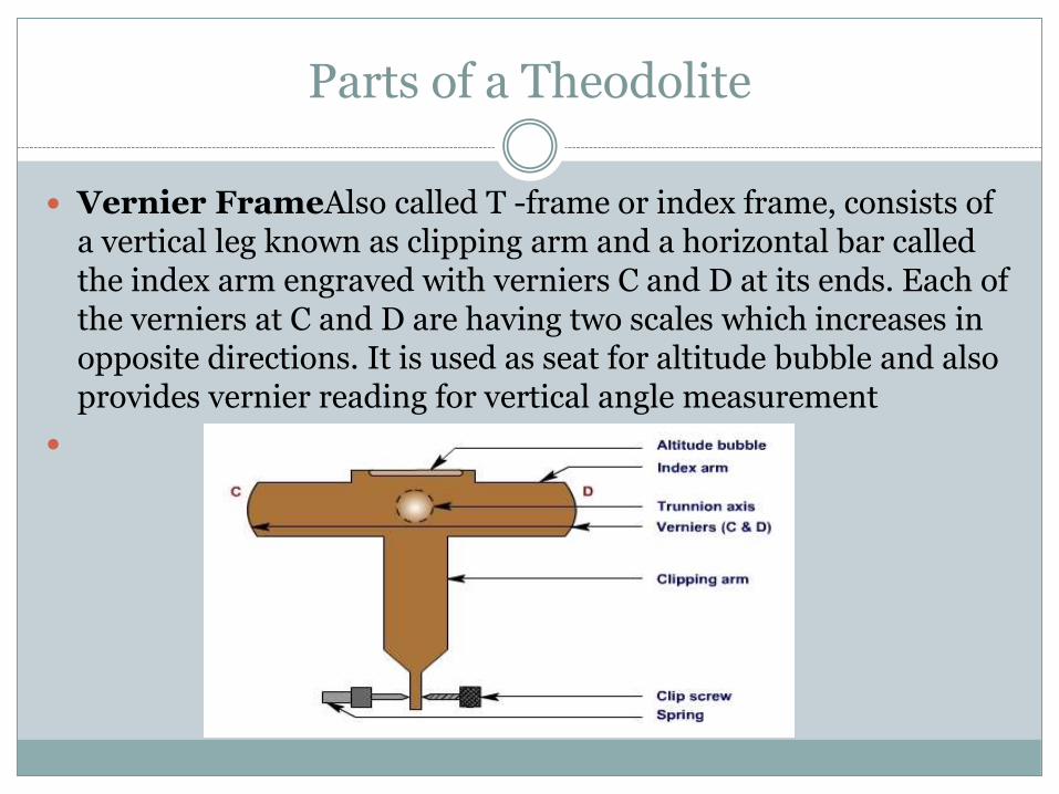
Vernier FrameAlso called T -frame or index frame, consists of a vertical leg known as clipping arm and a horizontal bar called the index arm engraved with verniers C and D at its ends. Each of the verniers at C and D are having two scales which increases in opposite directions. It is used as seat for altitude bubble and also provides vernier reading for vertical angle measurement

Parts of a Theodolite
Telescope – the function of telescope is to provide line of sight. The length of telescope varies from 100mm to 175mm. Most of the theodolites have internal focusing telescope.
Vertical Circle - The vertical circle is attached with the trunnion axis. It is engraved with a scale reading vertical angle in degrees and minutes. The vertical circle is divided into four quadrants each reading 0° to 90° with 0° - 0° either along vertical or in horizontal. It provides the main scale reading for vertical angle.
Altitude Bubble - A sensitive level tube placed on vernier frame is called altitude bubble. It is used to make horizontal axis truly horizontal.
Parts of a Theodolite
Screws - A theodolite instrument has number of screws as its component parts. These are classified into different types depending on their functions.
Levelling Screws
Clamp Screws
Tangent Screws

Parts of a Theodolite
Leveling ScrewsThese are present in the leveling head of a theodolite in between trivet and tribrach. These work in threaded holes in the tribrach arms and their lower ends rest in recesses in the trivet. These screws are used for leveling the instrument i.e., to make plate level axis truly horizontal.
Clamp screwsThese are used to fix the parts of a theodolite with which these are attached.
Lower Plate Clamp Screw
Upper Plate Clamp Screw
Vertical plate Clamp Screw

Parts of a Theodolite
Lower plate Clamp Screw - The clamp screw attached to the lower plate of a theodolite is called lower plate clamp screw. When it is tightened, the outer spindle gets fixed with the tribrach, and, thus, the lower plate gets fixed in position.
Upper plate Clamp Screw - The clamp screw attached with the upper plate of a theodoliteis called upper plate clamp screw. When it is tightened, the inner spindle gets fixed with the outer spindle and, thus, the upper plate gets fixed in position.
The manipulation of the upper plate and lower plate clamp screws provide three conditions:
When both the upper plate clamp screw and the lower plate clamp screw are tightened, the instrument gets fully fixed.
When the upper plate clamp screw is tightened and the lower plate clamp screw is opened, the instrument rotates on its outer axis, There is no relative motion between the two plate and the readings in the horizontal vernier scales do not change.
When the lower plate clamp screw is tightened, and the upper plate is opened, the instrument rotates on the inner axis with outer axis fixed. The readings in the horizontal vernier scales change.
Vertical plate Clamp Screw - It is used to clamp the telescope in any plane and hence at any desired vertical angle.

Parts of a Theodolite
Tangent Screws - With each clamping screw, there is a tangent screw present in the instrument to provide fine movement. The tangent screws work only after its clamping screws get tightened. Thus when the upper clamp screw has been tightened, small movement of the upper plate can be made by the upper tangent screw; when the lower clamp screw has been tightened, small movement of the lower plate can be made by the lower tangent screw and similarly for vertical clamp screw.
Tripod Stand - The theodolite is mounted on a strong tripod when being used in the field. The legs of the tripod are solid or framed. At the lower ends of the legs, pointed steel shoes are provided to get them pushed into ground. The tripod head has male screws on which the trivet of the leveling head is screwed.

Terms associated with measurement with theodolite
Centering – the process of setting up a theodolite on a ground station is known as centering.
Vertical axis – this the axis about which the instrument rotates in horizontal plane
Horizontal axis – it is the axis about which the telescope along with vertical circle rotates in vertical plane. It is known as trunnion axis.
Line of collimation – the line passing through the intersection of cross hairs of diaphragms and optical centers of objective is known as line of collimation.
Axis of plate level tube – it is a straight line tangential to longitudinal curve of the plate level tube at its centre.

Terms associated with measurement with theodolite
Face left observation while taking the reading if the verical circle is towards the left of the observer, it is called face left observation.
Face right observation – while taking readings if the vertical circle is towards the right of the observer then it is called face right observation (this condition is also called telescope inverted condition)
Transiting or plunging the telescope- The process of turning the telescope through 180 degree in vertical plane is known as transiting or plunging of theodolite.

Terms associated with measurement with theodolite
Changing the face – the operation of bringing the vertical circle from left to right or vice versa is called changing the face.
Swinging the telescope – the process of rotating the telescope about vertical axis is called swinging telescope.
A set of observations – finding of horizontal observation once with face right observation and other with face left observation is called one set of observation.

FUNDEMENTAL AXES OF THEODOLITE
I. Vertical axis
II. Trunnion axis
III. Line of collimation
IV. Altitude level axis
V. Axis of plate level
A theodolite is said to be in proper condition if the following conditions are satisfied:
I. The axis of the plate is perpendicular to the vertical axis
II. The trunnion axis is perpendicular to the vertical axis
III. The line of collimation is perpendicular to the trunnion axis
IV. The axis of the altitude level is parallel to the line of collimation


Temporary Adjustment of VernierTheodolite
At each station point, before taking any observation, it is required to carry out some operations in sequence. The set of operations those are required to be done on an instrument in order to make it ready for taking observation is known as temporary adjustment. Temporary adjustment of a verniertheodolite consists of following operations: Setting,
Centring,
Leveling and
Focussing.
Setting The setting operation consists of fixing the theodolite
with the tripod stand along with approximate leveling and centring over the station. For setting up the instrument, the tripod is placed over the station with its legs widely spread so that the centre of the tripod head lies above the station point and its head approximately level (by eye estimation). The instrument is then fixed with the tripod by screwing through trivet. The height of the instrument should be such that observer can see through telescope conveniently. After this, a plumb bob is suspended from the bottom of the instrument and it should be such that plumb bob should point near to the station mark.

Centring The operation involved in placing the vertical axis of the instrument exactly
over the station mark is known as centring. First, the approximate centringof the instrument is done by moving the tripod legs radially or circumferentially as per need of the circumstances.
It may be noted that due to radial movement of the legs, plumb bob gets shifted in the direction of the movement of the leg without seriously affecting the level of the instrument. On the other hand, when the legs are moved side ways or circumferentially, the plumb does not shift much but the level gets affected. Sometimes, the instrument and the tripod have to be moved bodily for centring. It must be noted that the centering and leveling of instrument is done recursively. Finally, exact centring is done by using the shifting head of the instrument. During this, first the screw-clamping ring of the shifting head is loosened and the upper plate of the shifting head is slid over the lower one until the plumb bob is exactly over the station mark. After the exact centring, the screw clamping ring gets tightened.

LevelingLeveling of an instrument is done to make the vertical axis of the instrument truly vertical. Generally, there are three leveling screws and two plate levels are present in a theodolite instrument. Thus, leveling is being achieved by carrying out the following steps
Step 1: Bring one of the level tube parallel to any two of the foot screws, by rotating the upper part of the instrument.
Step 2: The bubble is brought to the centre of the level tube by rotating both the foot screws either inward or outward. The bubble moves in the same direction as the left thumb.
Step 3: The bubble of the other level tube is then brought to the centre of the level tube by rotating the third foot screw either inward or outward. [In step 1 itself, the other plate level will be parallel to the line joining the third foot screw and the centre of the line joining the previous two foot screws.]
Step 4: Repeat Step 2 and step 3 in the same quadrant till both the bubble remain central.
Step 5: By rotating the upper part of the instrument through 180°, the level tube is brought parallel to first two foot screws in reverse order. The bubble will remain in the centre if the instrument is in permanent adjustment.
Otherwise, repeat the whole process starting from step1 to step5.

Focusing
To obtain the clear reading, the image formed by the objective lens should fall in the plane of diaphragm and the focus of eye-piece should also be at the plane of diaphragm. This is being carried out by removing parallax by proper focusing of objective and eye-piece. Thus, focusing operation involves two steps:
Focusing of the eye-piece lens
Focusing of the objective lens

Focusing of Eye-piece
The eye-piece is focused to make the appearance of cross hairs distinct and clear. This is being carried out in steps: First, point the telescope towards the sky or hold a sheet of white paper in front of the objective; Next, move the eye-piece in or out by rotating it gradually until the cross hairs appear quite sharp and clear.
Focusing of eye-piece depends on the eye-sight of observer and so for each observer it needs to adjusted accordingly.

Focusing of Objective It is done for each independent observation to bring the image of the object in the plane of cross hairs. It includes following steps of operation: First, direct the telescope towards the object for observation. Next, turn the focusing screw until the image of the object appears clear and sharp as the observer looks through properly focused eye-piece. If focusing has been done properly, there will be no parallax i.e., there will be no apparent movement of the image relative to the cross hairs if the observer moves his eye from one side to the other or from top to bottom.

MEASUREMENT OF HORIZONTAL ANGLES:
There are three methods of measuring horizontal angles:-
i) Ordinary Method.
ii) Repetition Method.
iii) Reiteration Method.
MEASUREMENT OF HORIZONTAL ANGLES:
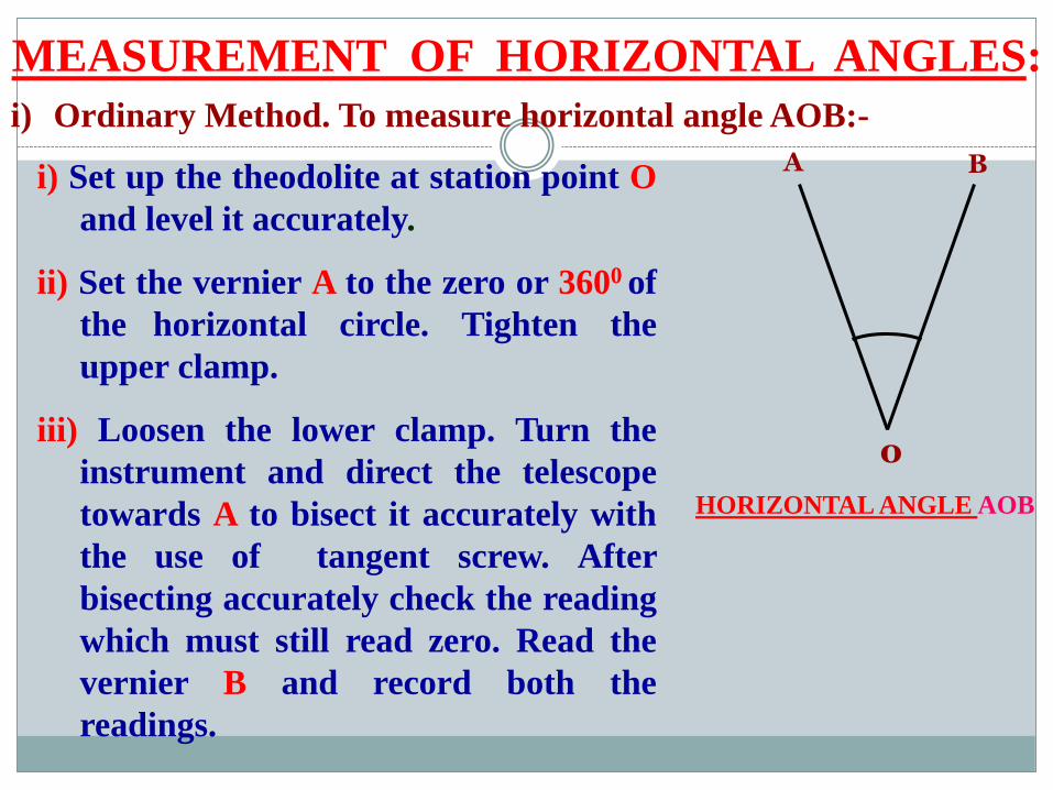
i) Ordinary Method. To measure horizontal angle AOB:-
i) Set up the theodolite at station point O
and level it accurately.
ii) Set the vernier A to the zero or 3600 of
the horizontal circle. Tighten the
upper clamp.
iii) Loosen the lower clamp. Turn the
instrument and direct the telescope
towards A to bisect it accurately with
the use of tangent screw. After
bisecting accurately check the reading
which must still read zero. Read the
vernier B and record both the
readings.
o
A B
HORIZONTAL ANGLE AOB

MEASUREMENT OF HORIZONTAL ANGLES:
iv) Loosen the upper clamp and turn the
telescope clockwise until line of sight
bisects point B on the right hand side.
Then tighten the upper clamp and
bisect it accurately by turning its
tangent screw.
v) Read both verniers. The reading of the
vernier a which was initially set at
zero gives the value of the angle AOB
directly and that of the other vernier
B by deducting 1800 .The mean of the
two vernier readings gives the value of
the required angle AOB.
o
A B
HORIZONTAL ANGLE AOB
MEASUREMENT OF HORIZONTAL ANGLES:
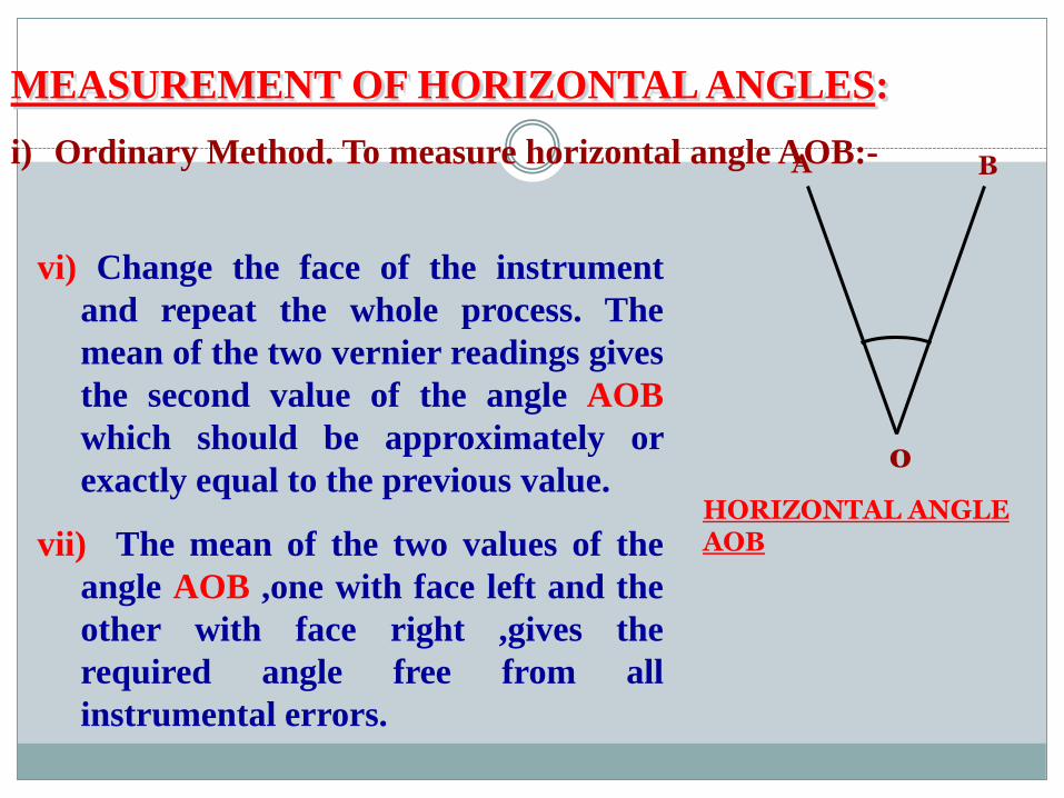
i) Ordinary Method. To measure horizontal angle AOB:-
vi) Change the face of the instrument
and repeat the whole process. The
mean of the two vernier readings gives
the second value of the angle AOB
which should be approximately or
exactly equal to the previous value.
vii) The mean of the two values of the
angle AOB ,one with face left and the
other with face right ,gives the
required angle free from all
instrumental errors.
o
A B
HORIZONTAL ANGLE AOB

MEASUREMENT OF HORIZONTAL ANGLES:
ii) Repetition Method.
This method is used for very accurate
work. In this method ,the same angle
is added several times mechanically
and the correct value of the angle is
obtained by dividing the accumulated
reading by the no. of repetitions.
The No. of repetitions made usually in
this method is six, three with the face
left and three with the face right .In
this way ,angles can be measured to a
finer degree of accuracy than that
obtainable with the least count of the
vernier.
o
A B
HORIZONTAL ANGLE AOB

MEASUREMENT OF HORIZONTAL ANGLES:
ii) Repetition Method.
To measure horizontal angle by
repetitions:-
i) Set up the theodolite at starting point
O and level it accurately.
ii) Measure The horizontal angle AOB.
iii) Loosen the lower clamp and turn the
telescope clock – wise until the object
(A) is sighted again. Bisect B
accurately by using the upper tangent
screw. The verniers will now read the
twice the value of the angle now.
o
A B
HORIZONTAL ANGLE AOB

MEASUREMENT OF HORIZONTAL ANGLES:
iii) Reiteration Method.
o
AB
Reiteration Method
C
D
This method is another precise and
comparatively less tedious method
of measuring the horizontal angles.
It is generally preferred when
several angles are to be measured
at a particular station.
This method consists in measuring
several angles successively and
finally closing the horizon at the
starting point. The final reading of
the vernier A should be same as its
initial reading.

MEASUREMENT OF HORIZONTAL ANGLES:
iii) Reiteration Method.
o
AB
Reiteration Method
C
D
…If not ,the discrepancy is equally
distributed among all the
measured angles.
Procedure
Suppose it is required to measure
the angles AOB,BOC and COD.
Then to measure these angles by
repetition method :
i) Set up the instrument over
station point O and level it
accurately.

MEASUREMENT OF HORIZONTAL ANGLES:iii) Reiteration Method.
o
AB
Reiteration Method
C
D
Procedure
ii) Direct the telescope towards
point A which is known as
referring object. Bisect it
accurately and check the reading
of vernier as 0 or 3600 . Loosen the
lower clamp and turn the telescope
clockwise to sight point B exactly.
Read the verniers again and The
mean reading will give the value of
angle AOB.
iii) Similarly bisect C & D
successively, read both verniers at-

MEASUREMENT OF HORIZONTAL ANGLES:iii) Reiteration Method (contd.).
o
AB
Reiteration Method
C
D
Procedure. each bisection, find the
value of the angle BOC and COD.iv) Finally close the horizon by sighting
towards the referring object (point A).
v) The vernier A should now read 3600.
If not note down the error .This error
occurs due to slip etc.
vi) If the error is small, it is equally
distributed among the several angles .If
large the readings should be discarded
and a new set of readings be taken.

MEASUREMENT OF VERTICAL ANGLES:
Vertical Angle : A vertical angle is an angle between the
inclined line of sight and the horizontal. It may be an
angle of elevation or depression according as the object is
above or below the horizontal plane.
A
B
O O
A
B
A
B
OHORI. LINE
HORI. LINE
β
HORI. LINE
VERTICAL ANGLEFig.a
Fig. b Fig. c
AOB= α+ β
AOB= α - β
β
β
αα
α

MEASUREMENT OF VERTICAL ANGLES:
To Measure the Vertical Angle of an object A at a station O:
(i) Set up the theodolite at station point O and level it
accurately with reference to the altitude bubble.
(ii) Set the zero of vertical vernier exactly to the zero of the
vertical circle clamp and tangent screw.
(iii) Bring the bubble of the altitude level in the central position.
(iv)The line of sight is thus made horizontal and vernier still
reads zero.
(v) Loosen the vertical circle clamp screw and direct the
telescope towards the object A and sight it exactly by using
the vertical circle tangent screw.
MEASUREMENT OF VERTICAL ANGLES:
(v) Read both verniers on the vertical circle, The mean of
the two vernier readings gives the value of the required
angle.
(vi) Change the face of the instrument and repeat the
process. The mean of of the two vernier readings gives the
second value of the required angle.
(vii) The average of the two values of the angles thus
obtained, is the required value of the angle free from
instrumental errors.

MEASUREMENT OF VERTICAL ANGLES:
For measuring Vertical Angle between two points A &Bi) Sight A as before , and take the mean of the two vernier
readings at the vertical circle. Let it be α
ii) Similarly, sight B and take the mean of the two vernier
readings at the vertical circle. Let it be
iii) The sum or difference of these readings will give the value of
the vertical angle between A and B according as one of the points
is above and the other below the horizontal plane. or both points
are on the same side of the horizontal plane Fig b & c
β


