Page 1
Doctoral School in Materials, Mechatronics
and Systems Engineering
Theoretical analysis and experimental investigation of contact fatigue and surface damage in prealloyed and diffusion bonded
sintered steels
Samuel Tesfaye Mekonone
June 2018
XX
X c
yc
le
Page 2
THEORETICAL ANALYSIS AND EXPERIMENTAL INVESTIGATION OF CONTACT FATIGUE AND SURFACE DAMAGE IN PREALLOYED AND DIFFUSION BONDED
SINTERED STEELS
Samuel Tesfaye Mekonone
E-mail: [email protected]
Approved by:
Prof. Molinari Alberto, Advisor Department of Industrial Engineering University of Trento, Italy. Prof. Ilaria Cristofolini, Advisor Department of Industrial Engineering University of Trento, Italy.
External reviewer:
Prof. Herbert Danninger Institute of Chemical Technology and Analytics Vienna University of Technology, Austria. Prof. Christoph Broeckmann, Department of Material Science and Engineering University of RWTH, Germany.
Commission: Prof. Vigilio Fontanari Department of Industrial Engineering University of Trento, Italy. Prof. Lorella Ceschini Department of Materials Engineering University of Bologna, Italy. Prof. Franco Bonollo Department of Management and Engineering University of Padova, Italy.
University of Trento,
Department of Industrial Engineering
June 2018
Page 3
i
University of Trento – Department of Industrial Engineering Doctoral Thesis Samuel Tesfaye Mekonone – 2018 Published in Trento (Italy) – by University of Trento ISBN: - - - - - - - - -
Page 4
ii
In loving memory of my grandmother, Emahoy Yengussa Molla
Page 5
iii
Abstract
The contact fatigue and surface damage of prealloyed (Fe-0.85Mo, Fe-1.5Mo) and
diffusion bonded (Ni-free, low-Ni, high-Ni) powder metallurgy (PM) steels were
investigated. Materials subjected to contact stress fail due to the nucleation of
subsurface cracks (contact fatigue cracks), nucleation of brittle surface cracks, and
surface plastic deformation. The occurrence of these contact damage mechanisms
was predicted using theoretical models, which were developed by assuming that
crack nucleation is preceded either by local plastic deformation (contact fatigue and
surface plastic deformation) or local brittleness (brittle surface cracks ) of the metallic
matrix. With reference to the mean yield strength of the matrix (mean approach) or
the yield strength of soft constituents (local approach), the models predict the
theoretical resistance of materials to the formation of damage mechanisms. The
models were then verified using experimental evidence from lubricated rolling-sliding
contact tests.
In addition, the effect of compact density and microstructures of materials on the
resistance to contact damage mechanisms was investigated. Density and
microstructure were modified by varying green density, alloying elements, sintering
temperature and time, and applying strengthening treatments: carburizing and shot
peening on prealloyed (homogenous microstructure) and carburizing,
sinterhardening and through hardening on diffusion bonded (heterogeneous
microstructure) steels.
The theoretical resistance to subsurface and surface crack nucleation in prealloyed
materials was predicted using the mean approach since the microstructure is
homogeneous. But the local approach is applied for diffusion bonded materials (Ni-
free and low-Ni); exceptionally, the mean approach was applied for some
homogeneous microstructure of Ni-free material sintered at a prolonged time.
However, the models have a limitation in predicting the contact damage mechanisms
in a high-Ni material. This issue may require further investigation to modify the
model.
Page 6
iv
Shot peening provides higher resistance to the nucleation of surface cracks. High
compact density, high sintering temperature and time, and sinterhardening improve
the resistance to contact damage mechanisms for Ni-free and low-Ni materials.
Page 7
v
Table of Contents
Abstract ....................................................................................................... iii
Chapter I ....................................................................................................... 1
1. Introduction ........................................................................................ 1
Chapter II ...................................................................................................... 4
2. Scientific Background ....................................................................... 4
2.1. Literature review on contact fatigue and surface damage of PM steels .................................. 4
2.2. Materials and process parameters ........................................................................................... 7
2.2.1. Alloying elements and powder mixing ............................................................................................... 7 2.2.2. Compaction and sintering parameters ............................................................................................... 9 2.2.3. Surface treatment and surface characteristics ................................................................................ 10
2.3. Contact mechanics.................................................................................................................. 12
2.4. Contact friction and surface tensile stress.............................................................................. 17
2.5. Surface damage and damage mechanism............................................................................. 18
2.6. Theoretical prediction of subsurface crack nucleation ........................................................... 21
2.7. Theoretical prediction of surface crack nucleation ................................................................. 22
2.7.1. Surface crack nucleation by plastic deformation ............................................................................. 23 2.7.2. Surface crack nucleation due to brittleness..................................................................................... 25
Chapter III ................................................................................................... 27
3. Material and Experimental Methods .............................................. 27
3.1. Materials .................................................................................................................................. 27
3.2. Experimental methods ............................................................................................................ 29
Chapter IV .................................................................................................. 36
4. Results and Discussion .................................................................. 36
4.1. Prealloyed steels: effect of Mo content of carburized steels and shot peening .................... 36
4.1.1. Rolling-sliding contact fatigue and wear damage of carburized materials ..................................... 37 4.1.2. Effect of shot peening ....................................................................................................................... 49
4.2. Ni-free diffusion bonded steel: effect of sinterhardening and density.................................... 57
4.2.1. Theoretical prediction and experimental validation of subsurface crack nucleation ..................... 62 4.2.2. Theoretical prediction and experimental results of surface plastic deformation ............................ 68
4.3. Low-Ni diffusion bonded steels: effect of sintering temperature ............................................ 75
4.3.1. Theoretical prediction and experimental validation of subsurface crack nucleation ..................... 80
Page 8
vi
4.3.2. Theoretical prediction and experimental results of surface plastic deformation ............................ 86
4.4. High-Ni diffusion bonded steels: carburizing vs. through hardening ..................................... 93
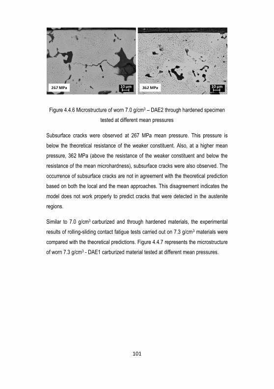
4.4.1. Theoretical prediction and experimental validation of subsurface crack nucleation ..................... 94 4.4.2. Theoretical prediction and experimental results of surface plastic deformation .......................... 103
4.5. Summary ............................................................................................................................... 110
Chapter V ................................................................................................. 115
5. Conclusions ................................................................................... 115
References ............................................................................................... 118
Scientific Production .............................................................................. 124
Acknowledgments ................................................................................... 125
Page 9
1
Chapter I
1. Introduction
Powder metallurgy (PM) is a net shape and cost-effective technology that is used to
produce mechanical components characterized by excellent dimensional and
geometrical precision with good mechanical properties. This technology is highly
competitive compared with other conventional processing methods such as casting,
machining or forging.
In conventional processes, first, the metallic powder is compacted in a die to form a
so-called green compact, then consolidated through heat treatment (that results in
intermetallic bonding) called sintering. Gears, bearings and cams are among the
most common PM components that are produced through the compaction and
sintering processes.
However, residual porosity is an inherent characteristic of these components. Since
porosity is a void in the microstructure, it determines the stress field significantly,
intensifying stress locally and reducing the load bearing section. Porosity reduces
mechanical properties of PM components, and provides lower resistance in
comparison to those of cast and wrought steel, in particular, ductility, toughness and
fatigue resistance.
The methods to improve the mechanical properties of PM materials are increasing
green density (compaction), improving pore morphology and sintering shrinkage
(sintering), strengthening the microstructure (sinterhardening, thorough hardening
and thermochemical treatments), increasing surface density (surface rolling), and
introducing residual stresses (shot peening). Increasing green density and
strengthening the microstructure are counteracting requirements since the former are
attained by using elemental powders, the latter by introducing alloying elements. The
use of diffusion bonded powders is the compromise between the two requirements,
but it results in heterogeneous microstructures, which are another peculiar
Page 10
2
characteristic of press and sintered steels. Microstructural heterogeneity causes a
non-homogeneous distribution of strength in the cross-section. Microstructural
heterogeneity of diffusion bonded steels may be reduced by increasing sintering
temperature and time.
For components that undergo a cyclic contact with a counteracting surface, contact
fatigue and related surface damage are the mechanisms by which the surface may
be failed. For instance, surface durability is a very demanding requirement for
components used in automobile engines, such as gears and cams, where the
surface is used to transmit dynamic contact load and rotating motion. Therefore, the
effect of porosity and microstructural heterogeneity on these surface and subsurface
damage mechanisms is needed to be investigated to propose the best strategies
(material, density, and strengthening process) that could enhance the performance.
Several years ago, GKN Sinter Metals SPA (a world-leading PM component
producer) and the University of Trento (Department of Industrial Engineering) started
cooperation to investigate the effect of porosity and microstructural heterogeneity on
the contact fatigue of diffusion bonded materials. The research mainly focused on
determining the resistance of contact fatigue. Recently, the collaboration extended to
include prealloyed steels (characterized by homogenous microstructure), other
diffusion bonded steels and to apply different strengthening treatments.
In this Ph.D. work, the contact fatigue and surface damage behavior of PM steels,
with homogenous and heterogonous microstructures, were investigated in terms of
resistance to the nucleation of subsurface cracks (contact fatigue), surface cracks
(brittle fracture) and surface plastic deformation. These phenomena are the possible
damage mechanisms that the material may experience when it is subjected to
contact stress.
Theoretical models were first developed to predict the nucleation of subsurface and
surface cracks, as well as surface plastic deformation; these models are formulated
starting from the theoretical analysis of the local plastic deformation and the brittle
fracture caused by pores. The models were applied with both the mean approach
Page 11
3
and the local approach, considering the mean mechanical properties of the matrix
and the mechanical properties of the weaker constituent, respectively.
The theoretical models were then validated using lubricated rolling sliding tests
carried out on different materials. Based on their resistance to different damage
mechanisms, the materials investigated were ranked, and the effect of composition,
alloying strategy, sintering temperature and time (in diffusion bonded steels),
strengthening treatment and shot peening was determined.
The thesis was divided into five chapters. The first chapter is the introduction.
Chapter II describes the scientific background, reviewing fundamental contact
mechanics theories and concepts about the contact fatigue and surface damage
behavior of PM materials, and describing the theoretical models. The investigated
materials and experimental methods are described in Chapter III. In Chapter IV, the
results are presented, discussed and summarized. Finally, the main highlights of the
project and some suggestions for future work are described in the concluding
chapter.
Page 12
4
Chapter II
2. Scientific Background
2.1. Literature review on contact fatigue and
surface damage of PM steels
Nowadays a large spectrum of structural parts is manufactured by Powder
Metallurgy (PM) aiming to exploit its potential to produce the complex geometries
and net shape components, with an efficient material utilization capabilities [1].
Cams, gears, and bearings are among the most popular machine elements produced
using this technology. These parts are often assembled in the systems and
automobile engines, which are used to transmit the dynamic contact load and torque.
During the service time, the surface undergoes a cyclic contact with counteracting
surface and is subject to high cyclic contact stress that leads the surface to eventual
failure.
The study of contact damage of PM steel uses a pioneering benchmark work of
Tallian [2], who first reported on wrought steels in which damage mechanisms are
categorized as surface and subsurface originated cracks. The former are classified
as wear damage (dominant in sliding contact) and the latter as contact fatigue
(dominant in pure rolling or rolling-sliding contact) [3–8] damage.
Subsurface and surface damage are associated with a higher stress field at the
contact zone that results in the formation of microcracks [2,9] and the propagation
and branching could generate surface wear particles. According to the nucleation
site and the size of the detached wear particles, different nomenclature of contact
fatigue and wear damage has been used by many authors. The most common terms
are reported in [10];
Micro and macro pitting: represent all surface originated contact fatigue
and wear damage
Page 13
5
Spalling: represents subsurface contact fatigue damage
Case crashing: represents all large-scale subsurface contact fatigue often
found in the case hardened materials.
The contact fatigue is different from the normal fatigue (push-pull, bending and
torsion) because the stress is a Hertzian stress state; pressure distribution is mostly
concentrated locally at a small contact area, and contact fatigue has no endurance
limit [11]. But the nomenclature and the approach used to investigate the contact
fatigue damage are similar to those used or the normal fatigue. The methodology,
characterization technique, and design approach for contact fatigue of PM materials
are highlighted in [12–17].
Contact fatigue of PM steel is a complex phenomenon and still an active research
area. That is because of the presence of many influencing parameters such as
material and process parameter, contact mechanics, contact friction and surface
conditions, subsurface defects microstructure, etc., all these paramteres make the
study very complex and multidisciplinary.
Figure 2.1.1 illustrates the diagram showing the parameters that could be considered
during the investigation of contact fatigue of PM steels.
Page 14
6
Figure 2.1.1 Parameters that affecting contact fatigue and wear damage
Porosity in the microstructure is the most determining factor and most studied
parameter in the history of PM materials. It is the void between interconnected
particles that introduces a negative impact on the surface damage resistance of the
materials. This effect was highlighted in the work of Haynes [18] and others
[16,19,20], which conclude that the fatigue endurance limit and fatigue life is affected
negatively by the presence of pores.
Even though the contact fatigue is different from the normal fatigue damage
mechanisms, there is no doubt that porosity also plays a determining factor in
contact fatigue life. The contact fatigue property of PM materials were reported in
several papers [21–24], which demonstrate that the fatigue strength is always lower
than that of the pore-free material. The main reasons behind the impact of porosity
on PM material are:
1. pores intensify stress locally [25],
2. pores are often crack nucleation sites [26],
3. pore connectivity and network are propagation pathways [27] and
Page 15
7
4. the presence of pores reduces the cross-section area that is involved in
supporting the load [28] (fraction of the load bearing section).
Locally, stress is intensified and becomes higher at the pore edge, and the first
crack nucleates in the microstructure surrounding the pore, then the crack growth
follows the weakest direction along the pore connectivity and networks.
Some of the contact fatigue crack formation and life-limiting parameters are
discussed briefly in the next paragraphs.
2.2. Materials and process parameters
Fatigue strength and other mechanical properties of sintered structural components
are influenced by alloying elements, sintering conditions, density and additional
surface treatments[13,29].
2.2.1. Alloying elements and powder mixing
Alloying elements can modify the microstructure, the yield and fatigue strength of
steel structural components, through their effect on hardenability. The influence on
the microstructure relates to the hardenability factor. Figure 2.2.1 represents the
amount of alloying element versus the hardenability factor: as provided by Höganäs
AB handbook.
Page 16
8
Figure 2.2.1 the effect of alloying element on hardenability factor
Manganese (Mn), molybdenum (Mo) and chromium (Cr) provide a higher
hardenability factor, which was also demonstrated in [30]. These elements are the
most common alloying elements that are applied in PM steels. In addition to the
hardenability factor, some alloying elements promote solution hardenings, such as
nickel (Ni) and copper (Cu).
Moreover, the type of powder alloying method can affect the microstructure.
Microstructure, microstructural homogeneity, and density depend on the alloying
strategy used to preserve compressibility when needed. The two most common
powder alloying in the conventional PM processes are prealloyed Fe-Mo base
powder and partially prealloyed (admixed Ni and Cu powders with prealloyed Fe-
Mo). Prealloyed Fe-Mo powder with the addition of graphite blend provides uniform
microstructure and properties with a certain limitation of compressibility. But partially
prealloyed powder improves powder compressibility and provides heterogeneous
microstructure [31]. Prealloyed admixed with only nickel powder (without copper)
avoids the formation of the secondary pore and increases the compact density. That
helps to reduce the pore connectivity and the pore network.
Ni stabilizes austenite, and it causes the formation of heterogeneous microstructure;
this would affect the contact fatigue behavior. However, with the different amount of
Page 17
9
austenite, the influence on the dynamic loading was investigated, and the specimen
with higher retained austenite shows higher fatigue life [32]. The increasing of fatigue
life may be due to the decomposition and transformation of austenite into martensite
above the critical load that improves the resistance to fatigue cracks. But in the
general case, the presence of austenite or Ni rich austenite reduces local yield
strength.
In the case of contact fatigue crack nucleation, the effect of austenite has not yet
been systematically studied. The little interest in this area by most researchers is due
to the complexity of the phenomena of contact stress distribution, and the interaction
between softer and harder constituent in the heterogeneous microstructure. A few
investigations on diffusion bonded steel with 4 % Ni have shown that contact fatigue
cracks are nucleated at a low applied load at the pore edges when the pores are
surrounded by the softer Ni-rich microstructures [33].
2.2.2. Compaction and sintering parameters
The correlation of the mechanical behavior of PM compacts with density is a
common approach. Achieving high density of structural component is the goal that
allows low porosity and pore size in the microstructure. Densification may be attained
by applying either higher compaction pressure or high sintering temperature [27]
techniques. These techniques eliminate certain pore populations and subsequently
reduce the fractional porosity. They also reduce local stress field and strain
accumulation during mechanical loading of a component. The associated effects
reported are that the yield strength and fatigue endurance limit increase with the
density [18,20,29,34,35].
Sintering temperature and sintering condition are important parameters affecting
pore morphology, density, microstructural homogeneity, and interparticle bonding.
The conventional sintering temperatures are between 1120 C to 1150 C, applied to
most conventional PM materials. Alloying elements characterized by their higher
oxygen sensitivity such as chromium and manganese need higher sintering
Page 18
10
temperatures up to 1250 C or above. High sintering temperature improves
interparticle bonding through the reduction of oxide layers. The final microstructure is
then characterized by well-homogenized and regular pore morphology.
Sinterhardening, in which martensitic transformation occurs just after the completion
of isothermal holding time in the furnace, is effective regarding the formation of
harder microstructure and is cost-effective. More than 80 % of the martensitic
microstructure can form during this process [36]. This microstructure could improve
contact fatigue and wear damage resistance. Based on the powder blending, the
application of sinterhardening provides a different result on the contact fatigue
resistance of the materials.
2.2.3. Surface treatment and surface characteristics
Among the different surface treatments, carburizing and shot peening are relatively
economical industrial processes which improve the contact fatigue and surface wear
damage. These two techniques modify the microstructure and behavior of the
surface layers.
Carburizing is an old and well known industrial process that modifys PM steel
surface. The case is enriched with carbon through a thermochemical diffusion from
the higher potential of the furnace atmosphere that is maintained in the austenite
field to the lower carbon potential of steel. Subsequent quenching forms the
tetragonal martensitic microstructure, which is characterized by high microhardness.
Therefore, depending on the characteristic case depth (d550 HV0.1), obtained through
optimal use of carbon potential, carburizing temperature and time, the resistance to
contact fatigue and wear damage can be greatly improved.
However, the presence of pores in the hardened matrix and its effect on the damage
and damage mechanism are not investigated in detail. In particular, the hardened
surface layers are prone to the formation of a brittle cracks, because the pore
become equivalent to a crack of a critical length[26].
Page 19
11
Shot peening is a process in which the stream of spherical shots impinging the
surface at high velocity and controlled conditions allows to achieve localized cold
working on the surface layers of mechanical parts [37–39]. The process introduces
surface plastic deformation and results in accumulation of compressive residual
stresses, strain hardening, and phase transformation. Depending on the
compressive residual stress profile and the peak stress, fatigue life of shot peened
parts improves due to the positive effect on extending crack nucleation period and
crack growth arresting [40].
Depends on the shot target microhardness and the amount of target retained
austenite, plastic deformation response is observed in the surface region [39,41,42].
In the case of harder shot and softer target, maximum compressive stress is
accumulated at the surface and reaches 60% of yield strength[41]. In this
combination, shot peening can improve surface resistance to contact fatigue and
wear damage with the proper use of the shot target property.
An additional effect of shot peening in porous materials is the densification of the
surface layers due to plastic deformation [38,43]. Investigation of shot peening on
sinterhardened parts show that surface pores are collapsed and closed using
ceramic shot and improved the contact fatigue resistance by 30% [44].
However, no literatures are available for the effect of shot peening on the contact
fatigue performance of case carburized parts, that is limited only to wrought
steel[40,45]. In this particular cases, densifying the surface is expected to have a
significant effect on the brittle crack resistance. What is more, shot peening
introduces surface roughness and elongated residual pore near the densified
surface. The positive effect of the technology on the contact damage is still under
investigation.
Page 20
12
2.3. Contact mechanics
Table 2.3.1 reports the list of parameters and their units utilized in the following
Table 2.3.1. List of symbols and definitions
Notation Definition Notation Definition
E elastic modulus
(N/mm2) Pmax maximum Hertzian pressure (N/mm2)
Poisson’s ratio Po mean Hertzian pressure (N/mm2)
b half contact width (mm) P contact pressure (N/mm2)
L contact length (mm) σx, σy, σz principal stresses (N/mm2)
R contact radius (mm) xz, yz principal shear stresses (N/mm2)
F applied force (N) σeq. equivalent stress (N/mm2)
Ec effective contact
modulus (N/mm2) τmax maximum shear stresses (N/mm2)
Rc effective contact radius
(mm) μ coefficient of friction
𝑥,𝑡 Surface tangential stress
Figure 2.2.1 represents the configuration of elastic contact between two cylindrical
surfaces and the pressure distribution within the contact width.
Page 21
13
Figure 2.3.1 Contact between cylindrical surfaces and parabolic pressure distribution
[46,47]
Through the action of a force, F, cylindrical surfaces with the radius R1 and R2,
brought into physical contact and initially forms a line contact. The parabolic pressure
distribution is build-up at the contact zone over the contact length, and the pressure
is the maximum at the center of the contact width [48]. This configuration of contact
represents the real machine element contacts, such as cam and gear teeth
interaction with the counterface. Often the contact area is small, and higher contact
stress is applied to the contact zone, that results in elastic or elastic-plastic
deformation in the surface layers.
According to the Hertzian contact theory (that assumes the contact is elastic, smooth
and non-conformal contact surfaces), two-dimensional compressive stress
distribution on the x-z plane is determined using the formulas from eq.(1) to eq. (5)
[49].
𝑥 =Pmax
b{𝑚 (1 +
𝑧2+𝑛2
𝑚2+𝑛2) − 2𝑧} (1)
Page 22
14
𝑧 =Pmax
b𝑚(1 −
𝑧2+𝑛2
𝑚2+𝑛2) (2)
𝑦 = ν(𝑥+ 𝑧) (3)
𝑚𝑎𝑥 = {𝑥𝑧 =
𝑧− 𝑥
2,𝑧
𝑏< 0.463
𝑦𝑧 =𝑧− 𝑦
2,
𝑧
𝑏> 0.463
(4)
σeq. =1
2[(𝑧 − 𝑥)
2 + (𝑦 − 𝑥)2+ (𝑧 − 𝑦)
2]0.5
(5)
Where, m and n are variables described in terms of space x, z coordinates and
determined using eq. (6) and eq. (7), respectively.
𝑚2 =1
2[ { (𝑏2 − 𝑥2 + 𝑧2)2 + 4𝑥2𝑧2}
1
2 + (𝑏2 − 𝑥2 + 𝑧2) ] (6)
𝑛2 =1
2[ { (𝑏2 − 𝑥2 + 𝑧2)2 + 4𝑥2𝑧2}
1
2 − (𝑏2 − 𝑥2 + 𝑧2) ] (7)
The sign of m and n are associated with the sign of z and 𝑥 axis, respectively.
The maximum or mean Hertzian pressure applied on the cylindrical contact surface
is determined using the relation given by eq. (8) and eq. (9).
PO = 0.78Pmax (8)
Pmax = 2F
πbL (9)
Half contact width b relates to the effective elastic modulus, the effective radius of
curvature, and the applied load and is determined using eq. (10)[48].
b = √4RcF
πLEc (10)
Page 23
15
Effective modulus and effective radius of curvature are evaluated using eq. (11) and
eq. (12)
1
Ec=
1−𝜈12
E1+1−𝜈2
2
E2 (11)
1
Rc=
1
R1+
1
R2 (12)
Figure 2.3.2 represents normalized Hertzian contact stress contours on x-z plane
and profile along the z-axis. Variable contact width and stress field are normalized by
half contact width and maximum Hertzian pressure, respectively.
Figure 2.3.2 Normalized contour of equivalent stress (a) and maximum shear stress
(b); and profiles of all contact stresses (c) [25]
The principal stresses distribution are always compressive, and the three different
stresses along the orthogonal axes introduce a triaxial state of stress [50,51]. This
triaxiality introduces elastic or plastic zone evolution of the contact region. Hertzian
Page 24
16
principal stress and subsurface plastic zone evolution during the contact fatigue are
investigated in [52,53] that shows large scale damage related to subsurface
maximum Hertzian stress.
Maximum stress found in the subsurface layer between 100 µm - 400 µm depth [47].
The Hertzian depth varies in this range, depending on the intensity of the pressure
distribution. The influence of applied force on half contact width, mean pressure, and
Hertzian equivalent stress of two different contacting materials (distinguished using
subscript 1 and 2) is shown in Figure 2.3.3.
Figure 2.3.3 Influence of applied force on half contact width, mean pressure, and
maximum Hertzian equivalent stress
Half contact width, mean pressure and maximum equivalent stress at the Hertzian
depth increase with the applied force.
However in real contact surface, the topographic characteristics and material
property are not uniform, and the pressure distribution and Hertzian depth change
within the contact zone. Contact stress distribution at irregular, discrete and asperity
contacts reviewed in [54–56]. All discrete asperity contact reduces the contact area
and the region around the asperity subjected to elastic or plastic deformation. On the
other hand, this type of contact results in a high frictional force at the surface.
Page 25
17
2.4. Contact friction and surface tensile stress
The surface stress is determined by the presence of surface irregularity, surface
area, and asperity contacts. When the surface is irregular due to the presence of
groove, valley or open porosity, the number of asperity contact increases. The
contact always associated with the generation of surface tangential stress due to
friction, which is very high near to the asperity contacts [57]. The surface tangential
stress profile on the x-y contact plane is determined using eq. (13)[49]
𝑥,𝑡 = − 2μP𝑚𝑎𝑥
{
[𝑥
𝑏+ √1 −
𝑥
𝑏2
2 ] 𝑥 ≤ −𝑏
𝑥
𝑏 − 𝑏 < 𝑥 < 𝑏
[𝑥
𝑏− √
𝑥
𝑏2
2− 1 ] 𝑥 ≥ 𝑏
(13)
Figure 2.4.1 represents the normalized axis-symmetric tangential stress profile along
the normalized x-axis with a variable coefficient of friction. The surface tangential
stress reaches the peak when x=b, and increases sharply with the coefficient of
friction.
Figure 2.4.1 Normalized surface tangential stress profile at a variable friction
coefficient
Page 26
18
The peak tangential stress at the surface affects the resistance to contact fatigue
and wear damage. Materials with a surface defect or surface pore that attribute
stress intensification: leads early damage even at lower stress.
On the other hand, surface stress induces material to flow towards the surrounding
pores results in surface densification that introduces both positive and negative
impacts on the surface damage resistance [15]. The positive effect is the matrix can
be strain hardened, load bearing surface can increase, and the unclosed pore act as
a suitable medium to trap derbies. These effects improve the resistance to dynamic
loading of the surface layer. On the contrary, densification can develop unstable
hydraulic pressure that alters damage mechanisms and could reduce the resistance
to surface damage. Moreover, when the lubricant is forced into an isolated surface
pore or crack front, strong hydrostatic pressure could build up during the contact.
Therefore, the mechanical action of hydrostatic pressure can strongly influence the
resistance to the surface crack formation. In particular, the shear mode of surface
damage can divert to the opening mode of damage by additional lubricant pressure
[58].
2.5. Surface damage and damage mechanism
Referring to the position where the cracks are nucleated and to the characteristics of
the final surface damage, cracks are classified into two types [2,59,60]:
a) Subsurface initiated cracks (contact fatigue cracks) and
b) Surface initiated cracks
Figure 2.5.1 shows an example of subsurface and surface initiated cracks observed
during rolling-sliding contact fatigue test of porous material.
Page 27
19
Figure 2.5.1 Types of surface damage and damage mechanisms
In both cases, cracks are nucleated at the pore edge and followed by crack
propagation and branching along the pore networks. The former grows towards the
surface, and the latter grows towards the depth. The dominant mode of failure
depends on the surface condition, lubrication, and material properties. For instance,
grinding and high quality of surface finish, with precise dimensional and geometrical
characteristics of the component, and under a good lubrication condition, cracks are
nucleated usually in the subsurface layers. But in the case of rough surface and poor
lubrication condition, cracks are nuclueated usually at the surface[50].
In particular, the sequence of events in subsurface originated damage are crack
nucleation in the subsurface followed by propagation and crack branching towards
the surface [61,62], then finally leads to particle detachment either by spalling or
case crashing. This damage is often characterized by a large scale contact fatigue
damage [26,61]. The characteristic depth or Hertzian depth at which cracks are
nucleated is affected by parameters like surface roughness and hardening depth
[50]. Crack formation relates to the maximum shear or equivalent stress at the
characteristics depth. In addition to the material properties, microstructural defects
such as inclusion, pore and oxide particle are often responsible for this type of
damage[6,63–65].
In the case of surface originated damage, the sequence of events are surface crack
nucleation followed by shallow shear mode crack growth towards the bulk and crack
deflection to the surface [61,62]. Surface damage is a detachment of particles (micro
and macro pitting) characterized by a shallow depth up to 10 µm [62]. Surface
Page 28
20
friction, surface shear stress, asperity contacts, and lubricant pressure are
responsible for the formation of surface cracks and the subsequent surface damage.
In addition to the surface tribological condition and porosity, surface microstructure
determines the response of the surface. The response may be either elastic, plastic
deformation or brittle fracture [39]. In the case of a softer/weaker matrix, the material
response is either elastic or plastic deformation. The plastic deformation zone is
where cracks are nucleated, and the severity of the deformation determines their
growth. However, in the case of a hard matrix, the formation of a brittle crack may
occur. In particular, the presence of surface pore in the low toughness matrix
(martensitic microstructure) increases the chance to the brittle crack formation. The
surface pore acts as a defect, and the size of the pore in the matrix determines the
surface originated brittle damage.
Regardless of the type of crack formation, contact fatigue and wear damage
mechanisms of PM materials follows the following steps [66,67]:
Stress field localization at the edge of the open and closed pore.
Dislocation pile up and strain accumulation at the sharpest edges of the
pores and along the grain boundary during every cycle contacts.
Local stress field promotes local plastic deformation that may result in
densification and crack nucleation.
Any lubricant entrapment to the face of the cracks promote crack tip
opening.
The growth of cracks in the pore connectivity network or towards the low
strength of matrix.
Formation of crack branching due to the interchangeability of a different
mode of contact fatigue failure.
Formation of debris either in the form of pitting or spalling.
Final surface damage.
Page 29
21
2.6. Theoretical prediction of subsurface crack
nucleation
Layers of materials underneath the contact surface are subjected to no proportional
triaxial stress distributions, which allows the contact zone always subjected to
alternative stress during every contact cycles. Unlike normal push-pull fatigue
loading, the maximum stress plane or points change during the cyclic contacts. This
phenomena results in higher complexity of predicting the contact fatigue cracks and
the wear damage. However, several theoretical models are available to predict
contact fatigue cracks. The existing models are [68]:
a. Equivalent stress approaches,
b. Maximum shear stress approaches,
c. Critical plane models, and
d. Empirical model.
Shear stress approach is more conservative and can reasonably apply for any
materials but with no indication of crack propagation direction. The same is true for
equivalent stress that cannot indicate crack growth direction, too.
In the case of porous materials, the equivalent stress and maximum shear stress
intensified locally, and the fraction of the load bearing surface is always smaller than
1 (because material ratio is below 100%) [25,61], such that the maximum stress ()
requires the correction parameters. The modified local stress may be determined
using eq. (14) and eq. (15), corresponding to the equivalent and shear stress failure
criteria [69,70,66]
𝜎 =𝜎𝑒𝑞 𝛽𝑘
𝛷+ 𝜎𝑅𝑒𝑠. (14)
𝜎 =2𝜏𝑚𝑎𝑥 𝛽𝑘
𝛷+ 𝜎𝑅𝑒𝑠. (15)
Where βk is notch sensitivity of the matrix and given by eq. (16)[71].
Page 30
22
βk = (Kt − 1)+ 1, (16)
where, Kt, is pore shape coefficient, that varies from 1 for the pore-free materials to
3 for porous materials, simply by considering the circular pore. is the coefficient of
matrix sensitivity that depends on the microstructural constituents: 0.3, 0.5 and 0.7
correspond to ferrite, pearlite, and martensite, respectively [71]. is the fraction of
load bearing sections, which depends on the amount of porosity and pore shape,
and is given by eq. (17)[28].
Φ = (1 − (5.58 − 5.57𝑓𝑐𝑖𝑟𝑐𝑙𝑒)𝜀)2 (17)
where fcircle is pore shape factor and is fractional porosity.
𝜎𝑅𝑒𝑠. is a compressive residual stress induced during either surface treatment, such
as shot peening.
Because of the local maximum stresses, subsurface crack nucleation preceded by
local plastic deformation. The model derived according to the comparison between
local stresses and the material yield strength. The relation is explained using eq.
(18),
𝜎 > 𝜎𝑦 (18)
The yield strength of heat treated matrix ( 𝜎𝑦 ) may be determined from the
microhardness using eq. (19) [72]
y =𝐻𝑉0.1
4.2 (19)
2.7. Theoretical prediction of surface crack
nucleation
Depending on the affecting parameters, such as roughness, lubrication regimes,
contact friction, surface hardness, and microstructural inhomogeneity, two types of
Page 31
23
surface cracks are most common during rolling-sliding contact fatigue. Those are
surface cracks due to surface plastic deformation and brittle cracks due to
brittleness.
2.7.1. Surface crack nucleation by plastic deformation
Three different stresses may accumulate at the surface,
1. Tangential stress due to the friction of irregular surface or asperity
contacts,
2. The mechanical action of the lubricant pressure, and
3. Surface Hertzian stress during the cyclic contact.
All these stresses may promote surface plastic deformation. Depending on the
coefficient of friction, typically when ≥0.3 [46,47] the position of Hertzian depth
moves to the surface, and the maximum Hertzian stress provides the biggest portion
of the three stresses. In the case of hydrodynamic or mixed mode lubrication,
Hertzian stress at the surface is still considerable for the analysis of surface plastic
deformation. The assumption considered for the analysis of surface plastic
deformation were;
- Surface plastic deformation expected due to surface stresses.
- The lubricant pressure could alter surface fracture mode; the influence is
ignored for PM material because lubricant possibly escapes through the
pore connectivity.
- In the case of heterogeneous microstructure, no combined response
(elastic, plastic and brittle fracture) adapted at the same time.
- Cracks may grow along the grain boundary and through the pore
networks.
By incorporating stresses and the assumptions, surface plastic deformation is
predicted using the Ashby model proposed in [73,74]. The criterion is comparing the
Page 32
24
yield strength of the matrix with surface contact stress. The formula (for PM
materials) is corrected using the factors that is correlated with microstructural
sensitivity and load bearing surface. Therefore, anticipated local plastic deformation
of the surface may predict using eq. (20).
σy = P0k
Mr2√1 + 92 + σRes. (20)
where, P0 is mean pressure, the constant k and Mr2 are correction factors
corresponding to the notch effect of the surface matrix and to the load bearing
surface, is coefficient of friction and σRes. is compressive residual stress.
Load bearing surface (Mr2) is defined as the actual area of material in contact and
supporting the unit load. In the case of a rough and porous surface, the material that
supports contact load is not continuous because of the presence of surface valley
and surface peak. Therefore, the material ratio supporting the unit load is always
below 100%. Load bearing surface can be determined from the material ration curve
(Abbott-Firestone curve) provided using surface profilometer measurement. For
example, Figure 2.7.1 shows surface profile over a certain length and the material
ratio curve obtained at the typical porous surface layer.
Figure 2.7.1 Surface profile and material ration curve of PM material
The valley in the surface profile represents surface pores that is not expected to
support the load. The material ration curve represent the distribution of peaks, and
Page 33
25
the load bearing surface can be determined from the curve by drawing a secant line
that connecting the inflicting points of the curve, and the point of intersection with the
horizontal line represents the load bearing surface.
However, the use of load bearing surface in eq. (20) depends on the type of contact
conditions. For example, in lubricated contact condition lubricant may fill the valleys,
and this could change the load bearing capacity of the surface. In the case of
hydrodynamic lubrication contact regime, the lubricant film may support the contact
load, in this condition, Mr2 is taken as 100%.
2.7.2. Surface crack nucleation due to brittleness
Tensile stress applied on the low toughness matrix could result in the formation of
brittle surface cracks. In particular, case hardened PM surface characterized by
higher hardness and lower toughness, in which the presence of open pore raises
tensile stress, and it also considered as cracks [26,75]. Therefore, relatively small
tensile stress may be sufficient to propagate brittle cracks of the surface layer. The
nucleation at the pore edges surrounded by the hard phases may be predicted using
eq. (21)
σt > σf (21)
where, σt, is the maximum tensile stress at the surface and f is stress at fracture.
σt is given by eq. (22) [61]
t =βk
Mr2 x,t (22)
where, βk is the notch effect of the surface matrix, Mr2 is load bearing surface and
x,t is the tangential stress at the surface.
The fracture stress f is determined using eq. (23) [26]
Page 34
26
f =KIC
(πa)12
(23)
where is a geometrical factor (10000.5), KIC is the fracture toughness of the matrix
and a is the pore size. KIC is related to a yield strength of the matrix and determined
using eq.(24) [69]
KIC =60000
y+300 (24)
Combining equations (21), (22), (23) and (24), a relation between the critical pore
sizes that causes brittle cracking and the maximum Hertzian pressure is obtained
using eq. (25)
a = k (0.78
P0)2 (25)
where K is material and geometry parameter (MPa2 m), defined by eq. (26)
k = 0.3183(KIC
2μ)2(Mr2
βk∗)2
(26)
Page 35
27
Chapter III
3. Material and Experimental Methods
3.1. Materials
Table 3.1.1 reports the investigated materials: codes, nominal chemical
compositions, and type of treatments applied to study lubricated rolling-sliding and
wear damage of PM materials.
Table 3.1.1 Code, nominal composition, and applied treatments of the investigated
materials
Material composition Code Applied treatments Powder grade
Fe-0.85Mo-0.35C A85Mo - Carburized
- Shot Peened
Prealloyed Fe-1.5Mo-0.3C AMo1
Fe-1.5Mo-2Cu-0.65C DDH2 - As sintered
- Sinterhardened
Ni-free diffusion
bonded
Fe-1Ni-1Cr-0.8Mo-0.6Si-0.1Mn-0.75C AS4300C75 - Sinterhardened Low-Ni diffusion
bonded Fe-0.4Ni-1.4Cr-0.8Mo-0.2Mn-0.75C EcosintC75 - Sinterhardened
Fe-4Ni- 0.5Mo-1.5Cu-0.3C DAE1 - Carburized High-Ni diffusion
bonded Fe-4Ni-0.5Mo-1.5Cu-0.5C DAE2 - Quenched
The powders were cold pressed in double uniaxial action compaction to obtain rings.
The green parts then sintered in a belt furnace with different belt speeds and
sintering temperatures. The applied belt speed is either 10 cm/min or 20 cm/min
depending on density; the faster speed applied to the lower density parts.
All materials were pressed and sintered in an industrial facility by GKN Sinter Metals,
Brunico, Italy.
Page 36
28
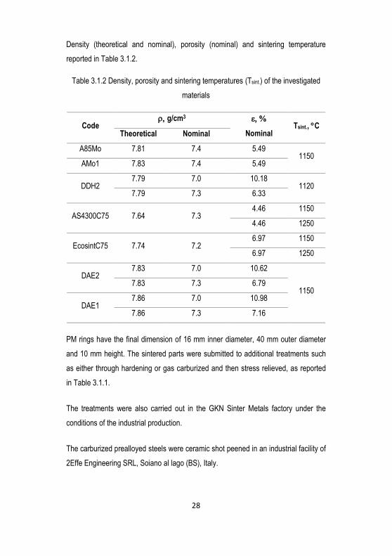
Density (theoretical and nominal), porosity (nominal) and sintering temperature
reported in Table 3.1.2.
Table 3.1.2 Density, porosity and sintering temperatures (Tsint.) of the investigated
materials
Code g/cm3
Nominal Tsint., C
Theoretical Nominal
A85Mo 7.81 7.4 5.49 1150
AMo1 7.83 7.4 5.49
DDH2 7.79 7.0 10.18
1120 7.79 7.3 6.33
AS4300C75 7.64 7.3 4.46 1150
4.46 1250
EcosintC75 7.74 7.2 6.97 1150
6.97 1250
DAE2 7.83 7.0 10.62
1150 7.83 7.3 6.79
DAE1 7.86 7.0 10.98
7.86 7.3 7.16
PM rings have the final dimension of 16 mm inner diameter, 40 mm outer diameter
and 10 mm height. The sintered parts were submitted to additional treatments such
as either through hardening or gas carburized and then stress relieved, as reported
in Table 3.1.1.
The treatments were also carried out in the GKN Sinter Metals factory under the
conditions of the industrial production.
The carburized prealloyed steels were ceramic shot peened in an industrial facility of
2Effe Engineering SRL, Soiano al lago (BS), Italy.
Page 37
29
3.2. Experimental methods
Density measurements were performed by the water displacement method with
weighing balance accuracy of 0.001 mg.
Before surface and subsurface microstructure characterization, all specimens
contaminated by oil or lubricant were cleaned properly using ligroin for seven hours
in ultrasound. Then, they were cleaned using ethanol for five minutes minimum.
Abbott Firestone curve and roughness of the die surface were analyzed using the
surface profilometer. The load bearing surface (Mr2) was determined. The surface
microhardness was measured using microhardness tester of 0.1 Kg. Its value is the
mean of three indentations carried out at different positions.
The maximum Feret pore diameter (Dmax) on the die surface and the porosity were
measured using the image analysis of three backscatter SEM images.
Metallographic specimens of longitudinal cross sections of the typical contact zone
were prepared. The specimens were mounted in the resin, gently grounded using
220-1200 grid silica carbide polishing paper. Pores were opened using 3 µm and 1
µm slurry polishing. The optical microscope was used to collect images from
unetched microstructure for pore parameter analysis. Three images were collected
for each material within a surface layer 400 m deep. The selection of this depth
size relates to the position of Hertzian equivalent stress, that often maximum up to
this depth. The subsurface pore parameters such as porosity (, pore area,
perimeter (P), equivalent pore diameter (Deq.) and maximum pore diameter (Dmax)
were characterized by using Image analysis on unetched microstructure. The
following procedures were followed to measure pore parameters along the cross-
sections.
First, pore parameters were measured on the three adjacent micrographs
from the surface up to 100 µm depth.
Then, the same pore parameters were collected from 100 µm to 200 µm,
200 µm to 300 µm and from 300 µm to 400 µm.
Additional pore parameter, fcircle, was determined for each pore size using
eq. (27)
Page 38
30
𝑓𝑐𝑖𝑟𝑐𝑙𝑒 =4πA
𝑃2 (27)
Mean value of the fcircle using the whole pore population and the bigger
pore size of 100%, 10% and 5% corresponding to the whole pore
population was calculated.
The etched microstructures were prepared and the reagent applied to reveal the
microstructure was 5% of Nital. Microhardness (HV0.1) was measured on these
microstructures. The two following approaches were applied during the indentation:
a. Three indentations carried out randomly, with the gap between at least
three times of diagonal indent lengths, up to the total 1 mm thick.
b. The measurement was carried out locally, that is simply by searching
each microstructural constituents in particular for the heterogeneous
diffusion bonded materials.
The surface residual stress and retained austenite profiles of carburized and shot
peened specimens were measured by X-ray diffraction by 2Effe Engineering. The
measurement conditions listed in Table 3.2.1.
Page 39
31
Table 3.2.1 X-ray diffraction measurement conditions of residual stress and retained
austenite of carburized and shot peened prealloyed steels
Incident Radiation Cr K Elementary Cell Cubic
Filter Vanadium Miller's Index (hkl) 211
Diffractometer configuration Multi-regression Yes
Detector type 30° Background subtraction Polynomial
Detector's angle range Strip 2position Free
Acquisition time 30 s 2angle 156.33°
Oscillation range +/-40° Young modulus 208000 MPa
Number of angles used 7 Poisson coefficient 0.28
Selection of Automatic Power supply 33 kV
Measurements method Static Current the tube's 85 µA
Materials Steel Collimator's diameter 1 mm
The measurement was takes placed within the interval of 50 µm up to 250 µm depth
from the surface. Shot peening and the analysis of residual stresses and retained
austenite were carried out.
Several lubricated rolling-sliding tests were carried out on disk to disk configuration
using an Amsler tribometer. Figure 3.2.1 shows the Amsler apparatus with the
contacting rings.
Page 40
32
Figure 3.2.1 Amsler Tribometer and contacting rings
The lubricant used was Castrol edge 5W-30. It was stored in the reservoir oil tank
and continuously delivered to the contact surface by the oil delivering chain. Contact
fatigue tests were performed at different mean Hertzian pressures with respect to the
reference pressure (the theoretical resistance to the contact fatigue crack nucleation)
that was determined by the theoretical analysis. The specimen and the counterface
disks rotate with an angular velocity of 400 rpm and 360 rpm, respectively. This
velocity difference results in a 10% sliding. This type of contact condition resulting in
the highest possibility of surface pitting of the contacting surfaces [52]. The tests run
up to one million cycles. The coefficient of friction was recorded during the whole
test.
After contact fatigue tests, the microstructure of the worn discs was investigated.
Using SEM and optical microscope, the presence of cracks in the surface and
Page 41
33
subsurface region was investigated. Figure 3.2.2 shows a schematic representation
of contact configuration and techniques of sectioning for metallographic preparation.
Figure 3.2.2 Contacting surfaces configuration and the procedure that shows sample
sectioning
Counterface disk is a heat treated 52100 bearing steel. The important properties are
reported using Table 3.2.2.
Table 3.2.2 Properties of counterface disc (bearing steel)
Material Nominal
composition
E (GPa) , g/cm3 HRc
Bearing steel Fe-1.5%Cr-1%C 210 7.81 60-65 0.3
The dimension and geometric characteristics of counterface disk are the same as a
sintered specimen. Since the maximum available force of the Amsler apparatus is
about 2000 N force, the counterface disk surface was chamfered to reduce contact
length (L) to increase the mean pressures applied to the specimens.
Page 42
34
The relationship between applied load and contact length were analyzed by
considering the specimen elastic modulus (155 GPa), specimen Poisson’s ratio
(0.27), and the variable contact length of counterface disk (L). Figure 3.2.3
represents the mean Hertzian pressure versus the force at a variable contact length.
Figure 3.2.3 Mean pressure at different contact lengths
As the contact length decrease from 10 mm to 3 mm (the minimum length), the
corresponding mean pressure increases. With the maximum available load 2000 N
and the contact length 3 mm the mean Hertzian pressure could rich about 1150
MPa.
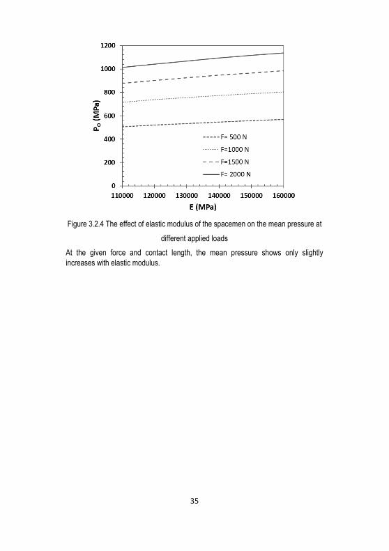
Since elastic modulus of the porous material varies with porosity, its effect on the
mean pressure was evaluated. Figure 3.2.4 represents the mean pressure as a
function of elastic modulus (specimen) determined at different applied loads with 3
mm contact length.
Page 43
35
Figure 3.2.4 The effect of elastic modulus of the spacemen on the mean pressure at
different applied loads
At the given force and contact length, the mean pressure shows only slightly
increases with elastic modulus.
Page 44
36
Chapter IV
4. Results and Discussion
4.1. Prealloyed steels: effect of Mo content of
carburized steels and shot peening
Shear and equivalent stress failure criteria are used to predict the formation of
subsurface cracks during rolling-sliding contact [66,76]. In theory shear stress
approach is more conservative and equivalent stress approach (maximum distortion
strain energy criterion) is more accurate to predict crack nucleation; however, due to
the peculiarity of PM materials, both approaches were verified.
Moreover, the effect of molybdenum content on lubricated rolling-sliding contact
fatigue and surface damage resistance was studied. The addition of Mo influences
the mechanical property without influencing the powder compressibility and
dimensional precision of the parts. In particular, the higher hardenability factor of this
element contributes a positive change of matrix properties. Tailoring Mo addition is
very common in the industry to minimize the costs of Mo that rises continuously in
the market. Here two different additions: 0.85%Mo (A85Mo) and 1.5%Mo (AMo1),
were considered and the influence on the formation of subsurface cracks was
studied using the two failure criteria approaches. The two steel were carburized and
shot peened.
However, the combination of high hardness, which attained through carburizing, and
the presence of residual pores (usually irregular in shape) may promote the
formation of brittle surface cracking. The effect was studied in [75,77] and shows that
the pore in a porous material acts as pre-existing cracks when the matrix
microhardness exceeds a threshold. The formation of the brittle cracks depends on
the pore size and the tensile stress. Therefore, in addition to the main damage
mechanisms of subsurface crack nucleation, brittle surface crack nucleation due to
surface tensile stresses was also studied.
Page 45
37
In this part, - lubricated rolling-sliding damage of a gas carburized prealloyed Fe-
0.85%Mo- 0.25%C and Fe-1.5%Mo-0.2%C sintered steel was investigated. The
occurrence of both subsurface and surface damage were analyzed theoretically, and
rolling-sliding contact fatigue tests were carried out to confirm the theoretical
predictions.
4.1.1. Rolling-sliding contact fatigue and wear damage
of carburized materials
Surface characteristics, such as hardness (HV10), microhardness (HV0.1), load
bearing surface (Mr2), mean roughness (Ra) and core roughness depth (Rk) of the
two carburized materials were measured and reported in Table 4.1.1.
Table 4.1.1 Surface characteristics of carburized rings measured at the contact
surface
Material HV10 HV0.1 Mr2 (%) Ra (µm) Rk (µm)
A85Mo 649 848 82.8 - 1.2
AMo1 673 845 81.5 - 1.0
Figure 4.1.1 shows unetched microstructure of the carburized prealloyed steels.
Figure 4.1.1 Unetched microstructure of carburized materials prepared using
backscatter electron scanning image
This image was used to measure pore parameter by image analysis. Figure 4.1.2
shows the profiles of fractional porosity (), pore shape factor (fcircle), elastic modulus
(E) and the fraction of load bearing sections ().
Page 46
38
Figure 4.1.2 Profiles of pore parameters and material property: , fcircle, , and E
Porosity is lower at the surface and increases to the bulk. The porosity of the two
materials is almost the same. The pore shape factor corresponding to the whole pore
population shows very little variation along the depth and is still the same for the two
materials. The fraction of load bearing sections was determined from the mean value
of the pore shape factor and the porosity distribution. The mean value of the fraction
of load bearing sections is 0.78 for A85Mo and 0.77 for AMo1. Elastic modulus was
determined from the fraction of load bearing section and the elastic modulus of pore
free material using eq. (28) [70].
E = Eo 0.5 28
where, E is the elastic modulus of the porous material, Eo is the elastic modulus of
pore free material, which is 210 GPa, andis a fraction of load bearing sections.
For the two materials, and E increases towards the surface because of the
decreasing of porosity and slight increasing pore shape factor.
Page 47
39
Figure 4.1.3 shows etched microstructure of the carburized A85Mo and AMo1
materials observed at SEM in a backscatter mode.
Figure 4.1.3 Microstructure of the carburized A85Mo (a, c) and AMo1 (b, d) steels:
surface (a, b) and core (c, d)
The main microstructural constituent of the surfaces are plate martensite and
retained austenite between plates, while the bulk microstructure is the mixture of
lower bainite and martensite. At the surface of AMo1 carburized steel, a few white
micro carbides were observed, as indicated by the white arrow. To observe carbide
formation, elements are mapped and shown in Figure 4.1.4. Carbide particles were
highlighted using the blue circular dotted lines.
Page 48
40
Figure 4.1.4 Element mapping of Fe-1.5%Mo-0.2%C carburized material using EDX
analysis
The local concentration of Mo confirms the formation of carbides. These carbide
particles are very fine, and the effect on the contact fatigue crack formation is
negligible.
The amount of retained austenite and the residual stress induced by carburizing
were measured. Figure 4.1.5 shows the profile of retained austenite and the residual
stresses of the carburized rings.
Figure 4.1.5 Retained austenite and residual stress profiles of carburized materials
Page 49
41
The amount of retained austenite is 12% at the surface and decreases moving
towards the bulk. The compressive residual stress induced by carburizing and heat
treatment is maximum at about 0.05-0.1 mm, and it is about -120 MPa. The
maximum residual stress depth is small. The influence on the reduction of stress at
Hertzian depth will be weak.
Figure 4.1.6 shows the microhardness profiles of carburized rings. Microhardness
profiles are typical of a carburized steel, with a case depth of about 800 m (d550HV)
thickness.
Figure 4.1.6 Microhardness profiles of carburized A85Mo and AMo1 steel
The dotted line represents the theoretical microhardness profile of martensite
produced by carburizing. The analysis needs the data of gas carburizing, such as
carbon potential (0.8 wt. %.) of the carburizing atmosphere, carburizing time (155
min), carburizing temperature (860 C), and C concentration in the bulk. Also, the
diffusion coefficient of C was determined using the model proposed in [78], and
carbon profile along the depth was determined using the equation proposed in [79].
Then carbon profile converts to the microhardness profile by correlating with the data
available in the literature [30].
Figure 4.1.7 shows the results of the theoretical analysis of the subsurface cracks in
the carburized rings, using the shear stress and the equivalent stress approach. The
calculation was made to determine the mean Hertzian pressure Po at which plastic
Page 50
42
deformation is expected to occur. This value is the theoretical resistance of the
carburized material to the formation of contact fatigue subsurface cracks.
Figure 4.1.7 Comparison between the maximum stress () and the matrix yield
strength (y) profiles of carburized steels: shear and equivalent stress approaches
The theoretical resistance of the carburized A85Mo steel is 797 MPa and 845 MPa
according to shear stress and equivalent stress failure criteria approach,
respectively. The theoretical resistance of carburized AMo1 steel is 833 MPa and
881 MPa according to shear stress and equivalent stress failure criteria approach,
respectively. Equivalent stress approach increases the mean pressure by 6% from
shear stress approach. The amount of Mo has no significant effects on the
theoretical resistance of the material.
Lubricated rolling-sliding tests were then carried out at different mean pressures on
the two materials.
Page 51
43
According to the reference mean pressures calculated using shear and equivalent
stress approach the following three mean pressures were applied on A85Mo
carburized steel.
- 750 MPa, lower than the theoretical resistance with both the approaches;
no subsurface cracks are expected;
- 830 MPa, intermediate between the theoretical resistances with the two
approaches;
- 950 MPa, higher than the theoretical resistance with both the approaches;
subsurface cracks are expected.
Test at 830 MPa was aimed at concluding which of the two approaches is more
reliable in the prediction of the resistance. Figure 4.1.8 shows the backscatter SEM
images of the worn specimens.
Figure 4.1.8 The microstructure of the carburized worn A85Mo material tested at
different mean pressures
Page 52
44
Subsurface cracks were observed only on the rings tested at 950 MPa. Therefore,
the evidence is in agreement with the theoretical approach based on the equivalent
stress failure criteria approach.
In addition to subsurface cracks, surface cracks were observed at 830 MPa and 950
MPa, as shown in figure 4.1.9. The observed cracks at 950 MPa are typical brittle
surface cracks.
Figure 4.1.9 The microstructure of the carburized worn A85Mo material tested at
different mean pressures showing surface cracks
These surface initiated brittle cracks are predicted simply by comparing critical crack
length (a), that is calculated using eq. (25), with measured pore sizes (half of
maximum Feret diameter) on carburized surfaces. Figure 4.1.10 represents
backscattered SEM image of carburized A85Mo surface with the distribution of the
surface pore maximum Feret diameters, which was measured by Image analysis.
Figure 4.1.10 Top surface view of carburized A85Mo ring and surface pore Feret
diameter distribution
Page 53
45
Figure 4.1.11 is the graphical representation of the theoretical analysis of the brittle
surface crack formation. The critical pore size responsible for surface crack
nucleation was calculated and plotted along with the tensile stress. Both critical pore
size and tensile stress are a function of the mean pressure. The friction coefficient
measured during the tests, and it is 0.014 (representative for all tests). The higher
the mean pressure, the higher the tensile stress and the smaller the pore size that is
expected to cause the formation of a surface cracks.
Figure 4.1.11 critical pore size responsible for surface crack nucleation and tensile
stress as a function of the mean pressure for the carburized A85Mo steel
The mean pressure at which the brittle surface cracks are expected to nucleate is
calculated using the biggest pore size, the pore size of the bigger pores accounting
for 5% and 10% of the pore population. Accordingly, 5% of the bigger pore
population predicts better than others the behavior of the material.
In the case of carburized AMo1 steel, referring to the mean pressures that are
calculated using the shear and equivalent stress approaches, three test mean
pressures were applied:
Page 54
46
- 800 MPa, lower than the theoretical resistance with both the approaches;
no subsurface crack are expected;
- 850 MPa, intermediate between the theoretical resistances with the two
approaches;
- 945 MPa, higher than the theoretical resistance with both the approaches;
subsurface cracks are expected.
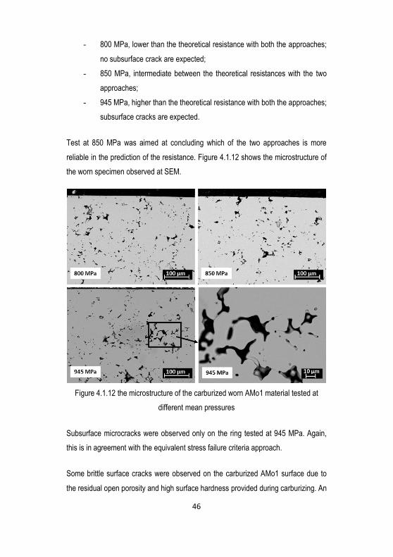
Test at 850 MPa was aimed at concluding which of the two approaches is more
reliable in the prediction of the resistance. Figure 4.1.12 shows the microstructure of
the worn specimen observed at SEM.
Figure 4.1.12 the microstructure of the carburized worn AMo1 material tested at
different mean pressures
Subsurface microcracks were observed only on the ring tested at 945 MPa. Again,
this is in agreement with the equivalent stress failure criteria approach.
Some brittle surface cracks were observed on the carburized AMo1 surface due to
the residual open porosity and high surface hardness provided during carburizing. An
Page 55
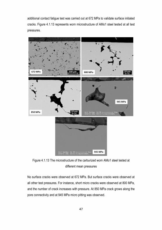
47
additional contact fatigue test was carried out at 672 MPa to validate surface initiated
cracks. Figure 4.1.13 represents worn microstructure of AMo1 steel tested at all test
pressures.
Figure 4.1.13 The microstructure of the carburized worn AMo1 steel tested at
different mean pressures
No surface cracks were observed at 672 MPa. But surface cracks were observed at
all other test pressures. For instance, short micro cracks were observed at 800 MPa,
and the number of crack increases with pressure. At 850 MPa crack grows along the
pore connectivity and at 945 MPa micro pitting was observed.
Page 56
48
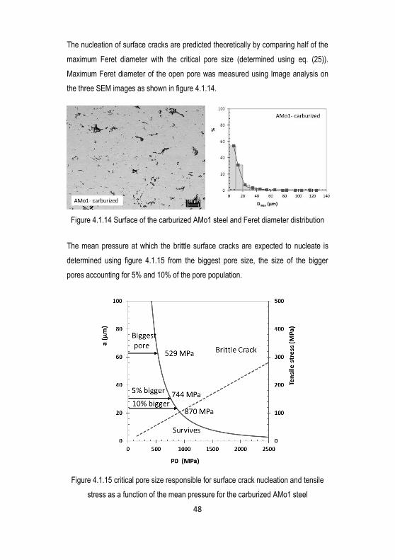
The nucleation of surface cracks are predicted theoretically by comparing half of the
maximum Feret diameter with the critical pore size (determined using eq. (25)).
Maximum Feret diameter of the open pore was measured using Image analysis on
the three SEM images as shown in figure 4.1.14.
Figure 4.1.14 Surface of the carburized AMo1 steel and Feret diameter distribution
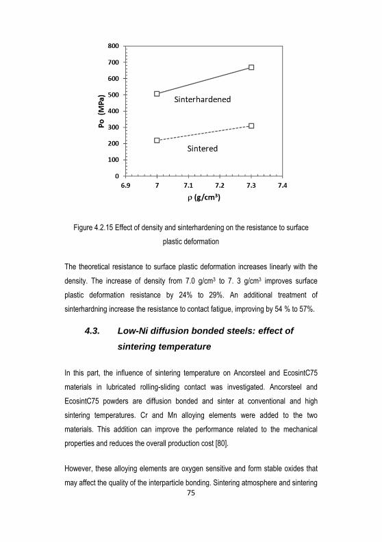
The mean pressure at which the brittle surface cracks are expected to nucleate is
determined using figure 4.1.15 from the biggest pore size, the size of the bigger
pores accounting for 5% and 10% of the pore population.
Figure 4.1.15 critical pore size responsible for surface crack nucleation and tensile
stress as a function of the mean pressure for the carburized AMo1 steel
Page 57
49
The comparison between theoretical and experimental results indicate that the
resistance to surface cracking during lubricated rolling-sliding tests properly
predicted form the size of the bigger pores accounting for 5% of the pore population.
4.1.2. Effect of shot peening
Table 4.1.2 reports measured surface characteristics, such as hardness (HV10),
microhardness (HV0.1), load bearing surface, the surface roughness (Ra) and core
roughness depth (Rk) of the two shot peened materials.
Table 4.1.2 Surface characteristics measured at the contact surface of shot peened
rings
Material HV10 HV0.1 Mr2 (%) Ra (µm) Rk (µm)
A85Mo 707 928 83.6 0.3 1.4
AMo1 693 967 83.2 0.2 0.6
The effect of shot peening on the contact fatigue and wear damage due to surface
densification, accumulation of compressive residual stress, and strain hardening was
investigated. Figure 4.1.16 represents unetched microstructure of shot peened
steels.
Figure 4.1.16 Unetched microstructure of the shot peened A85Mo, and AMo1 rings
prepared using an optical microscope
Shot peening promotes densification about 50 m to 70 m thick surface layers. The
densification mostly relates to the deformation of the softer austenite between
Page 58
50
martensitic plates. Figure 4.1.17 represents the retained austenite and residual
stress measured on shot peened specimens.
Figure 4.1.17 Retained austenite and residual compressive stress of shot peened
spacemen
Due to the stress/strain induced transformation of austenite into the martensite, the
amount of retained austenite is lower at the surface. Shot peening also introduces
higher compressive stress at the surface and decreases moving to the depth.
Using three different adjacent images as represented in Figure 4.1.16, pore
parameter were analyzed using image analysis. Figure 4.1.18 shows the profiles of
fractional porosity, pore shape factor, elastic modulus and a fraction of load bearing
sections.
Page 59
51
Figure 4.1.18 Profiles of pore parameters and material property: , fcircle, , and
elastic modulus
Shot peening shows a significant effect to reduce the surface porosity. The depth of
shot peening penetration is not distinguished, but smaller surface pores of carburized
material eliminated effectively. The pore shape factor is also lower at the surface due
to the collapsing of pore after shot peening. The fraction of load bearing sections was
calculated using the median value of the pore shape factor and porosity profile given
by eq. (17). It increases towards the surface because of the lower porosity at the
surface. The effect of shot peening on the pore parameters and property of A85Mo
and AMo1 are similar.
Figure 4.1.19 represents the microstructure of shot peened materials. The
microstructure is martensitic with a few retained austenite observed between
martensite plates. Apart from the amount of austenite, the microstructure of shot
peened surface is similar to that of the carburized surface (Figure 4.1.3).
Page 60
52
Figure 4.1.19 Microstructure of the shot peened materials: A85Mo (a) and AMo1 (b)
steels
The microhardness of shot peened microstructure was measured. Figure 4.1.20
shows microhardness profile of shot peened rings.
Figure 4.1.20 Microhardness profiles of shot peened A85Mo and AMo1 steels
The dotted line is the theoretical microhardness of carburized martensite.
Microhardness is higher only at the very near surface due to strain hardening
induced by shot peening, which is above the theoretical microhardness of carburized
surface.
Following the same procedure as carburized materials, the theoretical resistance of
shot peened surface determined. Figure 4.1.21 shows the results of the theoretical
calculation of the resistance to subsurface contact fatigue damage of the shot
peened materials.
Page 61
53
Figure 4.1.21 Comparison between the maximum stress () and yield strength (y)
profiles of shot peened matrix
The theoretical resistances of the shot peened A85Mo steels is 815 MPa and 868
MPa according to the shear stress and the equivalent stress failure criteria
approaches, respectively. The theoretical resistance of the carburized AMo1 steel is
841 MPa and 881 MPa according to the shear stress and the equivalent stress
failure criteria approaches, respectively. Since the compressive residual stress at the
Hertzian depth is quite small (Figure 4.1.17), shot peening shows no effect on the
resistance to subsurface crack nucleation. The theoretical resistance to contact
fatigue cracks of shot peened material is similar to the carburized material.
While the penetration of compressive stress and strain hardening is not deep
enough, the effect of compressive stress induced at the surface is very high. That
increases the resistance to surface wear damage. Similar to the subsurface crack
prediction, the brittle surface crack formation was predicted theoretically using brittle
fracture model.
Page 62
54
Figure 4.1.22 shows backscattered electron scanning image of the top surface of
shot peened rings.
Figure 4.1.22 Top surface view of the shot peened rings
Shot peening generates rough surface topology with few collapsed open pores.
Because of the surface densification by shot peening, the size of the pore is much
smaller than the carburized rings.
The maximum Feret diameter of pore was measured using image analysis, and the
distribution shown in Figure 4.1.23.
Figure 4.1.23 Distribution of Feret diameter of surface pore measured using image
analysis
The half of maximum Feret diameter of the bigger pores accounting for 5% and for
10% of the pore population are determined. It is then compared with the critical crack
length or pore size responsible to the formation of brittle cracking. Moreover, the
deformation of the surface deteriorates the surface profile, resulting in a higher
Page 63
55
friction coefficient (=0.04-0.1). But the main effect of shot peening is the decrease
of the surface tensile stress, as shown in figure 4.1.24.
Figure 4.1.24 Critical pore size responsible for surface crack nucleation and tensile
stress as a function of the mean pressure for the shot peened materials
Surface compressive residual stresses could cancel the tensile stress, which starts
increasing when the mean pressure reaches 1340 MPa and 1352 MPa on A85Mo
and AMo1 steels, respectively. Although the pore size on the shot peened surface is
higher than the critical one corresponding to 1340 MPa and 1352 MPa (less than 1
m), tensile stress is zero and not able to form the surface cracks. Therefore no
surface cracks are expected below such mean pressure. If mean pressure exceeds
these pressures, surface cracks nucleate.
Subsurface and surface crack nucleation on shot peened materials were investigated
by carried out lubricated rolling-sliding contact tests at different mean pressures.
Figure 4.1.25 shows the microstructure of the shot peened A85Mo steel tested at:
- 830 MPa (higher than the theoretical resistance based on the shear
stress approach but lower than the theoretical resistance based on the
equivalent stress approach) and,
- 950 MPa (higher than the theoretical resistance based on shear and
equivalent stress approach) mean pressures.
Page 64
56
Figure 4.1.25 Microstructure of worn shot peened A85Mo specimens at the
corresponding 830 MPa and 950 MPa test pressures
Subsurface cracks were not observed at 830 MPa, while at 950 MPa the subsurface
cracks were observed. The shot peened surface does not show surface cracks at the
two test pressures. The surface resistance to the formation of cracks may relate to
the presence of higher residual stress and strain hardening. The observed result is in
agreement with the theoretical calculation, which predicts no surface cracks up to
1340 MPa mean pressure.
Similar to A85Mo, AMo1 shot peened steel tested at different mean pressures.
Figure 4.1.26 shows the microstructure of worn shot peened AMo1 steels tested at:
- 850 MPa (higher than the theoretical resistance based on the shear
stress approach and lower than the theoretical resistance based on the
equivalent stress approach) and,
- 1100 MPa (higher than the theoretical resistance based on shear and
equivalent stress approach) mean pressures.
Page 65
57
Figure 4.1.26 Microstructure of the shot peened worn AMo1 specimens tested at 850
MPa, and 1100 MPa mean pressures
Subsurface cracks were not observed at 850 MPa. However, at higher pressure
1100 MPa, subsurface cracks were observed. The higher pressure produces a
higher number of cracks: most of them were nucleated at the pore edges and grows
along the pore connectivity, which are inclined to the contact surface. But no surface
cracks were observed at the test pressures. All the experimental evidence is in
agreement with the theoretical calculation.
4.2. Ni-free diffusion bonded steel: effect of
sinterhardening and density
In this paragraph, the effect of density and sinterhardening on the contact fatigue
damage of Cu bonded prealloyed Fe-Mo PM steel was investigated. Porosity,
microstructure and microstructural heterogeneity play a significant role in the
resistance to contact fatigue crack nucleation. Aiming to improve the contact fatigue
and wear damage, densifying and sinterhardening are most common techniques
applied to PM structural parts. Densifying reduces pore size and fractional porosity
Page 66
58
that reduce local stress field and improves the fraction of load bearing sections. An
additional cost effective sinterhardening produces martensitic microstructure, which
increases the matrix yield strength and subsequently improves the resistance to
plastic deformation.
The contact fatigue of DDH2 sinterhardened material was investigated only
considering the subsurface cracks preceded by local plastic deformation [44]. In the
present work, the effect of friction and surface shear stress on the occurrence of
surface plastic deformation studied.
In this section, rings from Fe-1.5%Mo-2%Cu-0.6%C (DDH2) steel, with target
densities of 7.0 g/cm3 and 7.3 g/cm3, were prepared. They produced in the sintered
and sinterhardened conditions. Subsurface and surface cracks at the pore edge
were predicted by comparing yield strength of the matrix constituents with Hertzian
equivalent stress and surface stress, as proposed using eq. (14) and eq. (20),
respectively. The allowable mean pressure at which the material could resist a
contact fatigue crack formation was estimated, then validated experimentally by
carried out rolling-sliding contact fatigue tests.
Table 4.2.1 reports density and mechanical properties (measured by tensile tests) of
sintered and sinterhardened materials.
Table 4.2.1 Density and mechanical properties of sintered and sinterhardened
materials
Material Treatment (g/cm3) y (MPa) UTS (MPa) E (GPa)
Fe-1.5Mo-2Cu-0.6C
(DDH2)
sintered
7.0 562 695 120
7.3 581 781 157
sinterhardened 7.0 809 941 120
7.3 979 1071 157
After longitudinal sectioning of the rings, the microstructure was observed at SEM.
The unetched microstructure of 7.0 g/cm3 and 7.3 g/cm3 sintered and the
sinterhardened material are illustrated in Figure 4.2.1.
Page 67
59
Figure 4.2.1 Unetched backscatter electron scanning microstructure of sintered and
sinterhardened materials
Qualitatively, the size of the pore is bigger on the lower density steel, and relatively
smaller on the higher density steel. Table 4.2.3 reports the quantitative analysis of
porosity (fcircle (corresponding to the whole pore population), and .
Table 4.2.2 Density and pore parameters measured from an image analysis
Treatment (g/cm3)
fcircle
nominal measured nominal measured
Sintered 7.0 6.98 0.10 0.11 0.58 0.57
7.3 7.26 0.06 0.07 0.62 0.73
Sinterhardened 7.0 7.04 0.10 0.10 0.57 0.58
7.3 7.23 0.06 0.07 0.65 0.74
The measured density is equivalent to the nominal one. The porosity is significantly
lower in the higher density specimens. Similarly, higher density material sintered at
higher isothermal holding time shows relatively higher pore shape factor than low
Page 68
60
density material (sintered at lower isothermal holding time). The fraction of load
bearing section is determined using the values of porosity and the pore shape factor
using eq. (17).
Figure 4.2.2 shows Sodium metabisulfite and 2% of Nital solution etched optical
microstructures of sintered and sinterhardened materials.
Figure 4.2.2 Etched optical microstructures of sintered and sinterhardened materials
The microstructure of the two sintered materials contains a mixture of pearlite (P),
bainite (B) and Cu-rich martensite (M). 7.0 g/cm3 sintered material comprises a
higher heterogeneous mixture, while 7.3 g/cm3 sintered material comprises the less
heterogeneous mixture. This difference is due to the longer sintering time that
enhances copper diffusion and homogenization in the ferrous matrix. Since copper
affects the transformations of austenite on cooling, its improved homogeneity in
austenite results in an improved homogeneity of the transformation products. After
sinterhardening, 7.0 g/cm3 material is again a heterogeneous microstructure and the
mixture of lower bainite (B) and martensite (M) constituents. The mixture of bainitic
and martensitic microstructural constituents surrounds both the bigger and smaller
Page 69
61
pores. In the case of 7.3 g/cm3 sinterhardening material, the matrix microstructure is
a homogeneous mixture of bainite (B) and martensite (M). Therefore, the
microstructural homogeneity of the higher density is gained by higher isothermal
holding time, while the microstructural heterogeneity of low density material relates to
the lower isothermal holding time.
Microhardness of the matrix was measured along the radial direction, from the
surface to 1 mm depth with 0.1 mm interval. Figure 4.2.3 illustrates microhardness
profiles of the weaker (selective indentation at the pearlite and bainite) constituent
and mean (random indentation) of the 7.0 g/cm3 and 7.3 g/cm3 sintered and
sinterhardened matrix.
Figure 4.2.3 Microhardness profiles of weaker constituent and mean of sintered and
sinterhardened materials
Due to the cooling rate differences between the surface and bulk, mean
microhardness of all materials slightly decreases from the surface to the bulk. Their
difference are related to the heat dissipation rate, and the surface layers are always
expected to cool faster than the bulk. Faster cooling rate enhances the formation of
Page 70
62
the martensitic microstructure at the surface. But, since the microstructure of the bulk
cooled at a lower cooling rate, weaker constituent such as bainite are expected to
form.
4.2.1. Theoretical prediction and experimental
validation of subsurface crack nucleation
By comparing the equivalent Hertzian stress with the yield strength (y) of the matrix,
the theoretical resistance to contact fatigue crack nucleation was predicted. Figure
4.2.4 represents the theoretical prediction of contact fatigue cracks on sintered and
sinterhardened materials of the two densities. Yield strength profiles of the matrix are
reported using dotted lines, as calculated from the microhardness of weaker
constituent and mean microhardness profiles. The maximum stress profiles are
reported using the solid lines.
Figure 4.2.4 Theoretical prediction of contact fatigue cracks on 7.0 g/cm3 and 7.3
g/cm3 sintered and sinterhardened materials by comparing yield strength (y) and
maximum stress ()
Page 71
63
The maximum stress corresponds to the mean Hertzian pressure values reported
that are indicative of the theoretical resistance to the nucleation of the subsurface
crack. The theoretical resistance to subsurface crack nucleation of all materials is
summarized below:
- 7.0 g/cm3 sintered material works without subsurface crack nucleation up
to 246 MPa mean pressure if the mean yield strength of the matrix is the
reference, but it works up to 180 MPa mean pressures if the yield strength
of pearlite constituent is the reference.
- 7.3 g/cm3 sintered material works without subsurface crack nucleation up
to 310 MPa mean pressure if the mean yield strength is the reference, but
it works up to 240 MPa mean pressure if the yield strength of pearlite
constituent is the reference.
- 7.0 g/cm3 sinterhardened material works without subsurface crack
nucleation up to 556 MPa mean pressure if the mean yield strength of the
matrix is the reference, but it works up to 425 MPa mean pressure if the
yield strength of bainite constituent is the reference.
- 7.3 g/cm3 sinterhardened material works without subsurface crack
nucleation up to 641 MPa mean pressure if the mean yield strength of the
matrix is the reference, but it works up to 536 MPa mean pressure if the
yield strength of bainite constituent is the reference.
As additional information, the Hertzian depths were calculated at the corresponding
mean pressures of Figure 4.2.4. Table 4.2.4 reports the Hertzian depth corresponds
to the mean pressures that could support by sintered and sinterhardened materials.
The Hertzian depth is used as the reference position to indicate the location of
expected cracks.
Page 72
64
Table 4.2.3 Hertzian depths at the corresponding mean pressures of Figure 4.2.4.
Material
Hertzian depth (µm)
Local approach
(yield strength of the
weaker constituents)
Mean approach
(yield strength of
the mean)
7.0 g/cm3 – sintered 40 70
7.3 g/cm3 – sintered 87 130
7.0 g/cm3 – sinterhardened 42 73
7.3 g/cm3 – sinterhardened 90 141
Contact fatigue test was carried out at different test mean pressures to validate the
theoretical resistance. Then the occurrence of cracks were investigated on the
microstructure of worn specimens. Figure 4.2.5 represents the microstructure of
worn 7.0 g/cm3 sintered materials, after the test at 189 MPa and 218 MPa mean
pressures.
Figure 4.2.5 Microstructure of worn 7.0 g/cm3 sintered specimen at different mean
pressures
Within the Hertzian depth about 40 µm, subsurface cracks were observed at the two
mean pressures. The two mean pressures are above the resistance determined with
reference to pearlite and below the resistance determined with reference to the mean
yield strength of the matrix. The observed results are in agreement with the
theoretical prediction based on the local approach (based on the resistance of
pearlite constituent that may resist up to 180 MPa pressure). Crack size and crack
Page 73
65
number increase with pressure. The observed cracks first grow parallel to the
surface then grow towards the surface, through pore connectivity, in the softer
pearlite nodules or along the interface of weaker/harder constituent. At lower
pressure, no contact fatigue cracks were observed in the microstructure. Therefore,
the experimental evidence indicates that the local approach predicts the occurrence
of subsurface crack formation very accurately than using the mean approach.
Figure 4.2.6 represents the microstructure of the worn 7.3 g/cm3 sintered materials,
after tests at 249 MPa and 374 MPa mean pressures.
Figure 4.2.6 Microstructure of worn 7.3 g/cm3 sintered specimen at different mean
pressures
Contact fatigue cracks were not observed at 249 MPa. This applied mean pressure
is higher than the theoretical resistance to contact fatigue cracks determined with
reference to pearlite (local approach). But at a higher mean pressure, 374 MPa,
which is higher than the theoretical resistance to contact fatigue cracks determined
with reference to the mean yield strength of the matrix (mean approach), a few
microcracks (indicated by white arrows in the figure) were observed. The nucleated
cracks grow through the pore connectivity. These cracks appear within the Hertzian
depth from the surface. The experimental result is in agreement with the theoretical
prediction determined based on the mean approach.
The difference between using the local approach and mean approach for the 7.0
g/cm3 and 7.3 g/cm3 sintered materials are associated with the isothermal holding
time. The former has heterogeneous microstructure (low isothermal holding time),
Page 74
66
and cracks may nucleate at a mean pressure higher than the resistance of pearlite
constituent. The latter has a more homogeneous microstructure (high isothermal
holding time) and crack nucleation is less sensitive to the weak constituent due to its
very low amount; it could nucleate only above the resistance of the mean yield
strength of the matrix.
With a similar trend, the resistance to contact fatigue crack formation was
investigated for sinterhardened steels. Figure 4.2.7 represents backscattered SEM
microstructure of worn 7.0 g/cm3 sinterhardened specimen tested at 404 MPa, and
529 MPa mean pressures.
Figure 4.2.7 Unetched and etched microstructure of worn 7.0 g/cm3 sinterhardened
specimens at different mean pressures
Subsurface cracks were not observed at 404 MPa. This pressure is below the
theoretical resistance determined with reference to the weaker bainite constituent
(local approach). However, at 529 MPa, which is above the theoretical resistance of
weaker constituent (local approach) but below the resistance determined with
reference to the mean yield strength of the matrix (mean approach), subsurface
Page 75
67
cracks were observed. Cracks are nucleated at the pore edge and grows either
towards to the weaker/softer constituent (bainite) or along the bainite/martensite
interface. The position of all detected cracks are within the Hertzian depth. The
experimental results are in agreement with the theoretical resistance determined with
reference to the bainite constituent.
Figure 4.2.8 represents unetched and etched microstructure of worn 7.3 g/cm3
sinterhardened specimens tested at 575 MPa and 678 MPa mean pressures. The
former and the latter pressures are above the theoretical resistance determined with
reference to the weaker constituent and determined with reference to mean
microhardness, respectively.
Figure 4.2.8 Microstructure of worn 7.3 g/cm3 sinterhardened samples tested at
different mean pressures
Subsurface cracks were not observed at 575 MPa mean pressures. This applied
mean pressure is above the theoretical resistance of the bainite. But subsurface
cracks were observed at 678 MPa, which is above the theoretical resistance
Page 76
68
determined based on the mean approach. The etched microstructure with higher
resolution shows the crack nucleation sites and growth paths. All cracks were
nucleated at the pore edge and grew along the pore connectivity.
Even after sinterhardening, the microstructural homogeneity still influences the type
of approaches used to determine the theoretical resistance of the material: the local
approach for low density material and the mean approach for high density material.
4.2.2. Theoretical prediction and experimental results of surface
plastic deformation
Figure 4.2.9 represents the top surface view of sintered materials before the contact
fatigue test. This top surface view is also representative of the sinterhardened
materials of the equivalent densities. The figure shows open pore population with a
size decreasing with density.
Figure 4.2.9 Top surface view of 7.0 g/cm3 and 7.3 g/cm3 sintered materials
Pore size distribution was analyzed using image analysis. Figure 4.2.10 represents
the pore size distribution. The bigger pore size decreases as the compact density
increases.
Page 77
69
Figure 4.2.10 Equivalent diameter of surface pore distribution measured by image
analysis
Before sectioning the ring, load bearing surface Mr2 and the surface microhardness
were measured using surface profilometer and microhardness tester, respectively.
Table 4.2.4 reports the nominal density, load bearing surface and microhardness of
the sintered and sinterhardened material.
Table 4.2.4 Surface hardness and load bearing surface of sintered and
sinterhardened materials
Material Mr2 HV0.1
weaker mean harder
7.0 g/cm3 – sintered 79 214 276 -
7.3 g/cm3 – sintered 83 210 269 -
7.0 g/cm3 – sinterhardened 79 450 674 804
7.3 g/cm3 – sinterhardened 83 453 709 804
Microhardness of the weaker and harder constituent measured by selective
indentation and surface microhardness is by random indentation. The microstructure
of the surface comprises a mixture of weaker and harder constituents. The weaker
constituent of the sintered material is pearlite, while the weaker constituent of
sinterhardened material is bainite.
Page 78
70
Since sintered and sinterhardened material contains the softer constituents such as
pearlite and bainite microstructure in the matrix, brittle surface cracks are not
expected to nucleate. Instead, the occurrence of surface plastic deformation was
investigated with reference to the weaker constituent and the mean microhardness.
Surface plastic deformation was predicted theoretically simply by comparing surface
stress with the yield strength of the surface layer. Figure 4.2.11 represents the
theoretical prediction of surface plastic deformation at a test pressure of sintered and
sinterhardened materials.
Figure 4.2.11 Theoretical prediction of surface plastic deformation of sintered and
sinterhardened materials
The theoretical calculation of surface plastic deformation done at all test pressures
(that were used to verify the formation of subsurface cracks). The calculation is
carried out based on the local and the mean approaches, and the results are
reported in the diagrams. The bisector line separates the material resistance regime
Page 79
71
to the surface plastic deformation regime; if the data points lie on the right side of the
line, the material is not expected to undergo plastic deformation, while data points on
the left side indicate the occurrence of surface plastic deformation. The results of
theoretical prediction are summarized as:
- 7.0 g/cm3 sintered materials: no surface plastic deformation at all test
pressures;
- 7.3 g/cm3 sintered material: surface plastic deformation at all test
pressures based on the local approach, no plastic deformation at a lower
pressure based on the mean approach;
- 7.0 g/cm3 sinterhardened material: surface plastic deformation at the
higher pressure based on the local approach;
- 7.3 g/cm3 sinterhardened material: no plastic deformation at a lower test
pressure based on the mean approach.
Then, the occurrence of surface plastic deformation investigated experimentally.
Figure 4.2.12 illustrates a top surface view of sintered worn samples tested at
different mean pressure.
Page 80
72
Figure 4.2.12 Top view of worn sintered specimens tested at different mean
pressures
Neither surface cracks nor surface densification due to plastic deformation were not
observed at 189 MPa and 218 MPa on 7.0 g/cm3 sintered materials. The
experimental evidence is in agreement with the theoretical prediction; with both the
local approach and the mean approach that predict no plastic deformation. In the
case of 7.3 g/cm3 sintered material, surface cracks, and densification were not
observed at 249 MPa mean pressure; this is in agreement with the theoretical
prediction based on the mean approach. However, at 374 MPa mean pressure the
surface is densified; this is coherent with the theoretical predictions made with the
two approaches.
With similar trend, the surface view of worn sinterhardened material was
characterized. Figure 4.2.13 illustrates the top surface view of sinterhardened
materials tested at different mean pressures.
Page 81
73
Figure 4.2.13 Top view of worn sinterhardened specimens tested at different mean
pressures
7.0 g/cm3 sinterhardened material does not show surface plastic deformation at 404
MPa. However, at high pressure of 529 MPa, surface densification by plastic
deformation was observed. The experimental evidence is in agreement with the
theoretical prediction based on the local approach. In the case of 7.3 g/cm3
sinterhardened material, surface densification was observed at 575 MPa test
pressure. Again, this is in agreement with the theoretical prediction based on the
mean approach. At 678 MPa surface densification by plastic deformation was
observed. The mean approach predicts plastic deformation at this pressure.
To summarize, the occurrence of subsurface cracks and surface plastic deformation
were determined for each density of sintered and sinterhardened conditions. Figure
4.2.14 shows the effect of density and sinterhardening on the resistance to contact
fatigue crack nucleation of materials.
Page 82
74
Figure 4.2.14 Effect of density and sinterhardening on the resistance to subsurface
crack nucleation
The resistance to subsurface cracks nucleation increases linearly with the density.
The increase in density from 7.0 g/cm3 to 7.3 g/cm3 improves crack nucleation
resistance by 34% to 42%. Also, applying sinterhardning treatment increases the
resistance by 52% to 58%.
The theoretical resistance for surface plastic deformation was calculated using the
mean coefficient of friction that was measured during the test, which is 0.13 for 7.0
g/cm3 and 0.09 for 7.3 g/cm3 materials. Figure 4.2.15 represents the effect of density
and sinterhardening on the theoretical resistance of surface plastic deformation of
materials.
Page 83
75
Figure 4.2.15 Effect of density and sinterhardening on the resistance to surface
plastic deformation
The theoretical resistance to surface plastic deformation increases linearly with the
density. The increase of density from 7.0 g/cm3 to 7. 3 g/cm3 improves surface
plastic deformation resistance by 24% to 29%. An additional treatment of
sinterhardning increase the resistance to contact fatigue, improving by 54 % to 57%.
4.3. Low-Ni diffusion bonded steels: effect of
sintering temperature
In this part, the influence of sintering temperature on Ancorsteel and EcosintC75
materials in lubricated rolling-sliding contact was investigated. Ancorsteel and
EcosintC75 powders are diffusion bonded and sinter at conventional and high
sintering temperatures. Cr and Mn alloying elements were added to the two
materials. This addition can improve the performance related to the mechanical
properties and reduces the overall production cost [80].
However, these alloying elements are oxygen sensitive and form stable oxides that
may affect the quality of the interparticle bonding. Sintering atmosphere and sintering
Page 84
76
temperature are set up, aiming to reduce particle surface oxide layers and to provide
homogenized microstructures. Therefore, the effect of sintering temperature on the
resistance to contact fatigue and surface crack nucleation was studied using the
theoretical approach and validated experimentally.
Edogas and H2/N2 are the sintering atmospheres used for the two materials sintered
at 1150 C and 1250 C, respectively.
AS1150 and AS1250 are codes used to represent Ancorsteel material sintered at
1150 C and 1250 C, respectively. Ecosint1150 and Ecosint1250 are codes used to
represent EcosintC75 material sintered at 1150 C and 1250 C, respectively.
Figure 4.3.1 represents unetched scanning electron microstructure of Ancorsteel and
EcosintC75 materials.
Figure 4.3.1 Scanning electron microstructure of Ancorsteel and EcosintC75
materials
Page 85
77
Pore parameters were measured using image analysis. Table 4.3.1 reports the
density, subsurface pore parameters and elastic modulus of the two materials
sintered at conventional and high sintering temperatures.
Table 4.3.1 Density, pore parameters and elastic modulus
Material (g/cm3) fcircle E, GPa
AS1150 6.83 0.11 0.58 0.56 120
Ecosint1150 7.01 0.09 0.59 0.61 137
AS1250 7.04 0.08 0.66 0.72 155
Ecosint1250 7.15 0.08 0.63 0.71 158
As expected, sintering at 1250 C provides a higher pore shape factor (fcircle), a
fraction of load bearing sections and elastic modulus than sintering at 1150 C.
Sintering temperature also influences the number of surface pores. By eliminating
the smaller pore with equivalent diameter < 2.35 µm, the total number of pore was
counted on the image of each material and sintering conditions. The number of pores
counted for AS1150 and AS1250 was 289 and 248, respectively. The number of
pores counted for Ecosint1150 and Ecosint1250 was 579 and 551, respectively. In
both materials, the number of pore decreases with increasing sintering temperature
The equivalent diameter and maximum Feret diameter of pores were compared to
show the effect of the sintering temperature on the two materials. The pore sizes
distribution of the two materials is represented using Figure 4.3.2.
Page 86
78
Figure 4.3.2 Pore size distribution of Ancorsteel and EcosintC75 materials sintered at
1150C and 1250 C
As expected, higher sintering temperature does not affect pore size significantly.
Figure 4.3.3 represents etched microstructure of Ancorsteel and EcosintC75
materials analyzed using an optical microscope.
Page 87
79
Figure 4.3.3. The etched optical microstructure of the Ancorsteel and EcosintC75
materials sintered at conventional and high sintering temperatures
The microstructure of AS1150 contains whiter region (martensite) and the brown
region (bainite), and the microstructure of Ecosint1150 is bainitic, a mix of upper and
lower bainite. The microstructure of the two materials sintered at high temperature is
still the mixture of the two constituents. AS1250 comprises bainite and martensite,
better homogenized than at low temperature. Similarly, the microstructure of
Ecosint1250 is an improved mixture of bainite and martensite.
Figure 4.3.4 represents the microhardness profiles of bainite and the mean one of
Ancorsteel and EcosintC75 sinterhardened materials.
Page 88
80
Figure 4.3.4 Microhardness profiles of Ancorsteel and EcosintC75 materials sintered
at conventional and high temperatures
The microhardness of the two materials increases with sintering temperature and is
constant within the Hertzian depth in all the cases. The increase of microhardness of
the two materials sintered at high temperature related to the removal of oxide surface
that facilitates better inter diffusion of alloying elements.
4.3.1. Theoretical prediction and experimental
validation of subsurface crack nucleation
Figure 4.3.5 represents the theoretical prediction of subsurface cracks for Ancorsteel
and EcosintC75 sinterhardened materials. Yield strength profile (represented by the
dote lines) of the matrix was calculated from the mean microhardness profiles and
that of the weaker constituents. The reported mean Hertzian pressure values are
corresponding to the theoretical resistance to the nucleation of the subsurface cracks
on the two materials sintered at low and high temptresses.
Page 89
81
Figure 4.3.5 Theoretical prediction of the materials using the mean and weaker
microhardness
The theoretical resistance to the subsurface crack nucleation was predicted based
on the local approach (with reference to the theoretical resistance of weaker
constituent) and the mean approach (with reference to the mean microhardness),
and the results are summarized as follows:
- AS1150 material is expected to survive at 376 MPa, and 342 MPa mean
pressures with reference to the mean and local approaches, respectively;
- Ecosint1150 material is expected to survive at 343 MPa (mean
approach), and 243 MPa (local approach) mean pressure;
- AS1250 material can resist subsurface crack nucleation at 642 MPa
(mean approach) and 504 MPa (local approach) mean pressures;
- Ecosint1250 material can resist subsurface crack nucleation at 599 MPa
(mean approach), and 481 MPa (local approach) mean pressures.
Page 90
82
The theoretical resistance to the contact fatigue crack nucleation of high temperature
sintered materials is higher than that of low temperature sintered material.
Hertzian depths were calculated for the above reported mean pressures. Table 4.3.2
reports the Hertzian depth that were determined with reference to local and mean
approaches.
Table 4.3.2 Hertzian depth referring to bainite and mean microhardness
Materials Hertzian depth (µm)
Local approach Mean approach
AS1150 70 77
Ecosint1150 46 66
AS1250 91 114
Ecosint1250 84 105
The Hertzian depth is the higher in all the case for materials sintered at high
temperature.
Figure 4.3.6 represents the microstructure of worn AS1150 samples tested at
different mean pressures.
Page 91
83
Figure 4.3.6 Microstructure of worn AS1150 spacemen tested at different mean
pressures
No subsurface cracks were observed at 281 MPa. The pressure is below the
theoretical resistance of weaker (bainite) constituent. At 377 MPa (equivalent with
the theoretical resistance of the weaker constituent), very few microcracks were
observed within the Hertzian depth. At higher pressure, 467 MPa (above the
theoretical resistance determined with the mean microhardness), longer subsurface
cracks nucleated within the Hertzian depth and grows towards the surface.
Therefore, the experimental evidence indicates that the local approach predicts the
nucleation of subsurface cracks.
Figure 4.3.7 represents the microstructure of worn Ecosint1150 samples tested at
different mean pressures.
Page 92
84
Figure 4.3.7 Etched microstructure of worn Ecosint1150 spacemen tested at different
mean pressures
At 228 MPa pressure, which is below the theoretical resistance of the weaker
(bainite) constituent, no subsurface cracks were observed. However, at higher
pressure 279 MPa, which is above the theoretical resistance of the bainite
constituent, contact fatigue cracks were observed at the Hertzian depth. Therefore,
the occurrence of subsurface cracks is predicted accurately using the local
approach.
With a similar trend, the theoretical resistance to contact fatigue cracks of high
temperature sintered materials was validated. Figure 4.3.8 represents the
microstructure of worn AS1250 sample tested at 485 MPa, and 556 MPa mean
pressures.
Figure 4.3.8 Microstructure of worn AS1250 samples tested at different mean
pressures
Page 93
85
No subsurface cracks were observed at 485 MPa; since the mean pressure is below
the theoretical resistance of the weaker constituent. But at 556 MPa, which is above
the resistance of the weaker constituent and below the resistance of the mean
microhardness, subsurface cracks were observed. These cracks found in the bainitic
microstructure that agrees with the theoretical resistance of the bainitic constituent
(local approach).
Figure 4.3.9 represents the microstructure of worn Ecosint1250 sinterhardened
specimen at two different test pressures.
Figure 4.3.9 Microstructure of worn Ecosint1250 specimen tested at different mean
pressures
Subsurface cracks were not observed at 414 MPa (which is below the theoretical
resistance of the bainite constituent). However, at higher test pressure, 501 MPa,
which is above the resistance of bainite and below the mean yield strength, cracks
were observed. These cracks are nucleated at the pore edges and grew towards the
surface along the pore connectivity.
Similar to materials sintered at a lower temperature, the experimental results of
materials sintered at higher temperature are in agreement with the theoretical
resistances with reference to the local approach. Moreover, sintering at high
temperature improves the resistance to the formation of contact fatigue cracks, this
relates to the improvement of a fraction of load bearing sections and yield strength of
the matrix.
Page 94
86
4.3.2. Theoretical prediction and experimental results
of surface plastic deformation
Since Ancorsteel and EcosintC75 materials contain bainite, brittle surface cracks are
not expected in this material and not investigated. However, the occurrence of
surface plastic deformation of the materials was investigated theoretically and
validated experimentally.
Similar to the study of subsurface cracks, pore parameter and microhardness of the
surface were analyzed first. Figure 4.3.10 represents the top surface (with a
magnification of 250x) of the two materials sintered at the conventional and high
sintering temperatures.
Figure 4.3.10 Top surface view of Ancorsteel and EcosintC75 materials sintered at
1150 C and 1250 C
Pore size and distributions were measured using image analysis. The effect of high
sintering temperature was observed on both materials where surface pores are
Page 95
87
relatively smaller in size and rounded in shape. Figure 4.3.11 represents the
distribution of maximum Feret diameter of the surface pore of the two materials.
Figure 4.3.11 Distribution of maximum pore diameters of Ancorsteel and EcosintC75
materials sintered at 1150 C and 1250 C
The maximum pore diameter for AS1150 and Ecosint1150 sintered at a lower
temperature is about 120 µm. Sintering at higher temperature decreases the pore
diameter to 75 µm and 85 µm in AS1250 and Ecosint1250, respectively. This
reduction indicates that higher sintering temperature may be beneficial to decreases
the surface pore size that may result in a significant effect on the resistance to
surface plastic deformation.
Table 4.3.3 reports the summary of surface characteristics (microhardness, load
bearing surface, and elastic modulus) of the two materials.
Page 96
88
Table 4.3.3 Surface characteristics of Ancorsteel and EcosintC75 materials
Material HV10 HV0.1
Mr2 (%) E (GPa) Bainite Martensite Mean
AS1150 305-352 375 762 400 86.2 195
Ecosint1150 203-261 250 - 339 77.3 185
AS1250 399-590 450 784 689 83.9 192
Ecosint1250 422-553 429 813 609 78.7 186
Since the microstructure comprises the softer constituents, the response of the
contact surface may undergo either elastic or plastic deformation, and the plastic
deformation is predicted theoretically and validated by observing the surface top
views and the microstructures.
The theoretical prediction of surface plastic deformation, the top surface view, and
microstructure of worn AS1150 specimen tested at different pressure are presented
using Figure 4.3.12.
Page 97
89
Figure 4.3.12 Theoretical prediction of surface plastic deformation (a), top surface
views (b and c) and microstructure (d) of worn AS1150 specimen tested at different
mean pressures
Diagram (a) presents the theoretical resistance of the AS1150 material with
reference to weaker/bainite constituent (local approach) and the mean
microhardness (mean approach). According to the local and the mean approaches,
the model predicts no surface plastic deformation at 377 MPa. At higher pressure,
467 MP, the surface stress is higher than the yield strength of the bainite constituent
as well as of the mean one, and the occurrence of surface plastic deformation is
predicted. The theoretical predictions are validated using the top surface view and
the microstructure of worn surfaces. Accordingly, figure (b) shows no surface plastic
deformation at the lower mean pressure, and figure (c) and (d) also validates the
occurrence of surface plastic deformation (that results in densification, surface
cracks/shear lips), respectively.
Figure 4.3.13 represents the theoretical prediction, the surface top views, and the
microstructure of the worn Ecosint1150 test at different mean pressures.
Page 98
90
Figure 4.3.13 Theoretical prediction of surface plastic deformation (a), surface top
views (b and c) and microstructure (d) of worn Ecosint1150 spacemen tested at
different mean pressures
The theoretical prediction is presented using figure (a). Surface plastic deformation is
expected at 228 MPa and 297 MPa with reference to the local approach and 297
MPa with reference to the mean approach; since the surface stress is higher than the
yield strength of bainite. This prediction is validated using the experimental
observation of top surface view (b, c) that shows surface densification at both
pressures. The microstructure of worn specimen (d) also indicates the presence of
surface cracks and pitting at a higher pressure. Theoretical resistance of the
surfaces sintered at low temperature may be predicted accurately using the local
approach.
With a similar trend, the theoretical resistance and experimental evidence of surface
plastic deformation of materials sintered at high temperature were studied. Figure
4.3.14 represents the theoretical prediction, the top surface view, and the
microstructure of worn AS1250 specimen tested at different pressures.
Page 99
91
Figure 4.3.14 Theoretical prediction of surface plastic deformation (a), top surface
views (b and c) and microstructure (d) of worn AS1250 specimen tested at different
mean pressures
Theoretical prediction of the surface plastic deformation is presented using figure (a).
According to eq. (20), surface stress is a function of applied mean pressure, notch
sensitivity, friction and load bearing surface. But at the given surface porosity,
roughness and applied mean pressure, the surface stress is higher on the matrix that
are characterized as the mean (martensitic matrix) than on the bainitic matrix
because both matrix have different notch sensitivity values: 0.7 for mean matrix
(more martensitic constituent) and 0.5 for bainitic matrix. Surface plastic deformation
is not predicted at 485 MPa and all test pressures with reference to the local
approach and the mean approach respectively. The theoretical predictions are
validated using the experimental results: figure (b) shows no surface plastic
deformation at a lower pressure, and figure (c) and (d) shows densification, surface
cracks, and shear lips.
Page 100
92
Figure 4.3.15 represents the theoretical prediction and top surface view of
Ecosint1250 materials tested at different mean pressures.
Figure 4.3.15 Theoretical prediction of surface plastic deformation (a), surface top
views (b, c) of worn Ecosint1250 spacemen tested at different mean pressures
The theoretical prediction is presented using figure (a). At the given surface porosity,
roughness and applied mean pressure, the surface stress is higher on the matrix that
are characterized as the mean (martensitic matrix) than on the bainitic matrix
because both matrix have different notch sensitivity values: 0.7 for mean matrix
(more martensitic constituent) and 0.5 for bainitic matrix. The model predicts no
surface plastic deformation at 414 MPa with reference to the resistance of bainitic
matrix (local approach) and at all pressures with reference to the resistance of the
martensitic matrix (mean approach). The prediction is also validated using the
experimental results: the top surface view (b) shows no surface densification and
cracks at a lower pressure and slight densification at the higher pressure.
Page 101
93
Similar to the materials sintered at a low temperature, the theoretical resistance of
the surfaces sintered at a high temperature may be predicted accurately using the
local approach. The similarity relates to the microstructural heterogeneity, and both
low and high sintering temperature material comprise the weaker constituent, such
as bainite. In all the cases high sintering temperature increases the resistance to
surface plastic deformation because of the reduction of surface pore size,
improvement of matrix yield strength and load bearing surface.
4.4. High-Ni diffusion bonded steels: carburizing
vs. through hardening
Apart from the porosity, the second most important parameters are microstructure
and microstructural heterogeneity. Harder and homogeneous microstructures
provide better resistance to contact fatigue and wear damage. However,
heterogeneous microstructures provide a mix of weaker and harder constituents that
may affect the resistance to contact fatigue and wear damage, due to the local
variation in the matrix yield strength. To modify the microstructure, carburizing
(effective on the surface) and heat treatment (effective on the entire cross section)
are common techniques applied on PM structural parts that transform the material
into a martensitic microstructure. These techniques increase the matrix yield strength
and therefore improves the resistance to plastic deformation.
The influence of density, carburizing and heat treatment on the crack formation
during lubricated rolling-sliding contact was studied in [81,82,60,83]. As already
highlighted, a higher resistance can be gained by reducing porosity and providing a
martensitic microstructure. However, the presence of a weaker constituent in a
heterogeneous microstructure may affect the resistance to crack nucleation and is
not well studied yet.
Ni is added to improve the powder compressibility and matrix toughness; however,
the final microstructure comprises harder martensite and weaker Ni-rich austenite.
This type of microstructural combination may influence the resistance to crack
nucleation. Therefore, the application of surface carburizing and heat treatment may
Page 102
94
not show a significant effect on the elimination of local weaker/softer regions. This
weaker constituent may decrease the resistance to contact fatigue and wear damage
of the typical heterogeneous microstructure.
The contact fatigue and wear damage of Fe-0.5%Mo-4%Ni-1.5%Cu-0.5%C
sinterhardened PM steel were studied in [33]. The paper is analyzed only the
formation of subsurface cracks using theoretical prediction and experimental
validation. However, the effect of densifying, carburizing and heat treatment on the
formation of subsurface and surface crack formation has not yet studied.
This study investigates the effect of density and different treatments on the contact
fatigue crack nucleation of Fe-0.5%Mo-4%Ni-1.5%Cu PM steel. Carbon added in the
form of graphite, 0.3% for the carburized, and 0.5% C for the heat treated conditions.
Ring specimens were produced with target densities of 7.0 g/cm3 and 7.3 g/cm3.
Subsurface and surface crack nucleation during lubricated rolling-sliding contact
were studied using the theoretical models described in eq. (14) and eq. (20) and
validated experimentally using the contact fatigue tests.
4.4.1. Theoretical prediction and experimental
validation of subsurface crack nucleation
Figure 4.4.1 shows the microstructure of carburized (DAE1) and through hardened
(DAE2) materials at the optical microscope.
Page 103
95
Figure 4.4.1 Unetched microstructure of carburized and through hardened materials
with different densities
Porosity, pore area, and perimeter were measured on unetched microstructure using
image analysis, from which density, pore shape factor, elastic modulus and a fraction
of load bearing sections were determined. Table 4.4.1 reports the pore parameters
and selected properties of the two DAE materials.
Table 4.4.1 Pore parameter and material properties of carburized and through
hardened diffusion boned materials
Material g/cm3
fcircle E, GPa Nominal Measured
DAE1 7.0 7.04 0.11 0.58 0.57 118
DAE2 7.0 7.03 0.11 0.60 0.58 123
DAE1 7.3 7.25 0.08 0.66 0.73 154
DAE2 7.3 7.30 0.07 0.62 0.74 160
Page 104
96
The measured density corresponds to the nominal one. As expected, the porosity of
the two materials decreases with increasing density. As a correction factor, the
fraction of load bearing surface was calculated in terms of porosity and pore shape
factor using eq. (16). Determination of pore shape factor (fcircle) of a fraction of load
bearing sections and elastic modulus is based on the mean values of the whole pore
population, which was measured on the three different adjacent microstructures. All
pore parameters and elastic modulus increase with density.
Figure 4.4.2 represents etched microstructure of carburized and through hardened
materials.
Figure 4.4.2 Etched microstructure of carburized and through hardened DAE
materials with different densities
The microstructure of the carburized DAE1 material is the combination of white area,
which is Ni-rich austenite, dispersed within the brown martensite matrix. The
microstructure of the DAE2 material is almost similar to DAE1, but bainite is present
in the dark areas. The amount of white area is higher in through hardened
Page 105
97
microstructure than in the case of the carburized materials, due to the lower carbon
content in the final microstructure.
The microhardness was measured randomly (mean approach) without selecting
each constituent and also locally by selecting the weaker constituent (local
approach) on etched microstructure. Figure 4.4.3 shows the microhardness profiles
of the weaker constituents and the mean microhardness profiles of carburized and
through hardened materials.
Figure 4.4.3 Microhardness profiles of carburized and through hardened materials
with different densities
The mean microhardness profiles of the carburized material show a gradient within 1
mm thick surface layer, while constant profiles are displayed by the through
hardened (DAE2) material. Microhardness increases with density, in all the cases.
Cases depths of carburized material are 0.5 µm and 0.6 µm for 7.0 g/cm3 and 7.3
g/cm3 density, respectively. The difference between case depth and microhardness
with density is due to the use of different isothermal holding times, which is longer for
Page 106
98
the high density material. The microhardness profile of the weaker constituent (Ni-
rich austenite) is constant along the longitudinal cross-sections.
The yield strength profiles of the matrix were calculated from the Ni-rich austenite
(softer constituent) microhardness profile and the mean microhardness profile. It is
then compared with the Hertzian equivalent stress to predict the nucleation of
subsurface cracks. Figure 4.4.4 represents the theoretical prediction of subsurface
cracks in carburized and through hardened diffusion bonded materials.
Figure 4.4.4 Theoretical prediction of contact fatigue cracks based on the local and
mean approaches of carburized and through hardened materials
Table 4.4.2 summaries the mean pressures, which results in the nucleation of
subsurface cracks in the two materials, predicted using different approaches.
Page 107
99
Table 4.4.2 Theoretical resistance of carburized and heat treated materials to the
nucleation of contact fatigue cracks
Materials
Mean pressure (MPa)
Local approach
(austenite yield
strength )
Mean approach
(mean yield
strength )
7.0 g/cm3- DAE1 306 468
7.0 g/cm3- DAE2 283 375
7.3 g/cm3- DAE1 524 658
7.3 g/cm3- DAE2 530 580
The theoretical resistance (the resistance to subsurface crack nucleation)
determined using the local approach is always lower than the one determined by the
mean approach since the local approach is formulated based on the yield strength of
the softer (Ni-rich austenite) microstructural constituent.
When the applied mean pressure exceeds the reported pressures cracks may
nucleate due to the local plastic deformation at the Hertzian depth. Table 4.4.3
reports the Hertzian depths determined at the mean pressures corresponding to the
theoretical resistance to crack nucleation in the materials.
Table 4.4.3 Hertzian depths at the mean pressures corresponding to the theoretical
resistance of austenite and mean microhardness matrix
Material Hertzian depth (µm)
Local approach
(austenite yield
strength )
Mean approach
(mean yield
strength )
7.0 g/cm3- DAE1 66 99
7.0 g/cm3- DAE2 58 77
7.3 g/cm3- DAE1 94 117
7.3 g/cm3- DAE2 92 102
Page 108
100
The nucleated crack position is found shallower in the austenite phase and low
density materials, and relatively deeper in the high density materials. The Hertzian
depth increases with the increases of mean pressures, which was also indicated by
figure 4.4.4.
Rolling-sliding contact fatigue test was carried out on the carburized and through
hardened materials, at the pressures below and above the theoretical resistance to
the formation of contact fatigue cracks (that was determined using the local and
mean approaches). Figure 4.4.5 represents the microstructure of worn 7.0 g/cm3 -
DAE1 carburized material tested at different mean pressures.
Figure 4.4.5 Microstructure of worn 7.0 g/cm3 - DAE1 carburized specimen tested at
different mean pressures
Subsurface cracks were observed at 238 MPa. This applied mean pressure is below
the theoretical resistance of the softer constituent. Also, a test at 412 MPa mean
pressures, which is higher than the theoretical resistance of the weaker constituent
and lower than the resistance determined from the mean microhardness, resulted in
subsurface cracks. These subsurface cracks were nucleated within the Hertzian
depth and grew towards the surface along the austenite phase and the pore
connectivity.
Figure 4.4.6 represents the microstructure of worn 7.0 g/cm3 - DAE2 through
hardened material tested at different mean pressures.
Page 109
101
Figure 4.4.6 Microstructure of worn 7.0 g/cm3 – DAE2 through hardened specimen
tested at different mean pressures
Subsurface cracks were observed at 267 MPa mean pressure. This pressure is
below the theoretical resistance of the weaker constituent. Also, at a higher mean
pressure, 362 MPa (above the resistance of the weaker constituent and below the
resistance of the mean microhardness), subsurface cracks were also observed. The
occurrence of subsurface cracks are not in agreement with the theoretical prediction
based on both the local and the mean approaches. This disagreement indicates the
model does not work properly to predict cracks that were detected in the austenite
regions.
Similar to 7.0 g/cm3 carburized and through hardened materials, the experimental
results of rolling-sliding contact fatigue tests carried out on 7.3 g/cm3 materials were
compared with the theoretical predictions. Figure 4.4.7 represents the microstructure
of worn 7.3 g/cm3 - DAE1 carburized material tested at different mean pressures.
Page 110
102
Figure 4.4.7 Microstructure of worn 7.3 g/cm3 – DAE1 case hardened specimen
tested at different mean pressures
Subsurface cracks were observed at 462 MPa, which is below the resistance of the
weaker constituent. The experimental evidence is still not in agreement with the
theoretical prediction referring to the theoretical resistance of the weaker constituent.
Also, a test at 608 MPa that is higher than the resistance of the weaker constituent
but lower than the resistance determined from the mean microhardness, cracks were
nucleated in the Ni-rich austenite region.
Figure 4.4.8 represents the microstructure of worn 7.3 g/cm3 - DAE2 through
hardened material tested at different mean pressures.
Figure 4.4.8 Microstructure of worn 7.3 g/cm3 - DAE2 through hardened specimen
tested at different mean pressures
Subsurface cracks were observed at 469 MPa. This applied pressure is below the
theoretical resistance of the weaker constituent. Also, at a higher pressure, 622 MPa,
Page 111
103
subsurface cracks were observed. These cracks nucleate at the edge of the pores
and growth through the weaker (Ni-rich austenite) constituent. However, the
formation of cracks at a lower pressure are not in agreement with the theoretical
prediction based on the weaker constituent.
Similar to the low density materials, the application of local approach is not
applicable to predict the nucleation of subsurface cracks accurately in high density
materials. Therefore, the theoretical model that was developed based on the
comparison of yield strength and equivalent stress need to be verified to investigate
carburized and through hardened DAE materials.
4.4.2. Theoretical prediction and experimental results
of surface plastic deformation
Surface pore parameters were measured on 250X images collected at SEM. Figure
4.4.9 represents the top surface view of DAE1 and DAE2 materials.
Figure 4.4.9 Top surface view of DAE1 and DAE2 materials with the two densities
Page 112
104
Also, Vickers hardness and microhardness were measured on the contact surfaces,
and load bearing surface Mr2 was determined from the Abbott Firestone curves.
Table 4.4.4 reports the summary of surface characteristics (microhardness, load
bearing surface, and elastic modulus) of the two materials.
Table 4.4.4 Surface characteristics of the DAE1 and DAE2 materials
Material HV10 HV0.1 Mr2 (%) E (GPa)
7.0 g/cm3 - DAE1 268-373 300-700 78 185
7.0 g/cm3 - DAE2 361-442 263-588 78 185
7.3 g/cm3 - DAE1 379-453 400-750 82 190
7.3 g/cm3 - DAE2 435-624 402-749 82 190
Surface hardness, microhardness, load bearing surface and elastic modulus of the
carburized material is equivalent to through hardened material, and the parameters
increase with density.
The occurrence of surface plastic deformation, at different mean pressures reported
in the previous sections, was predicted theoretically with the local and the mean
approaches. The theoretical prediction of surface plastic deformation or densification
is illustrated using Figure 4.4.10.
Page 113
105
Figure 4.4.10 Theoretical prediction of surface plastic deformation on 7.0 g/cm3 and
7.3 g/cm3 carburized and through hardened materials
Except the top right side graph, surface stress is higher on the mean matrix (more
martensitic matrix) than on the austenite matrix (weaker constituent) at the same
mean pressure. This difference is related with the use of different notch sensitivity
values for different constituents: 0.7 for martensitic constituent (mean matrix) and 0.4
for austenite matrix. The dotted bisector line separates the material resistances from
surface plastic deformation regimes, and the theoretical results are summarized
below:
- 7.0 g/cm3 - DAE1 material: surface plastic deformation is predicted only at
412 MPa with reference to the theoretical resistance of Ni-rich austenite.
- 7.0 g/cm3 - DAE2 material: surface plastic deformation is expected at a
362 MPa with reference to the local and mean approaches, and not
expected at a lower pressure in all the cases.
Page 114
106
- 7.3 g/cm3 - DAE1 material: surface plastic deformation is predicted only at
608 MPa with reference to the theoretical resistance of Ni-rich austenite.
- 7.3 g/cm3 - DAE2 material: surface plastic deformation is expected at 622
MPa with reference to the theoretical resistance of Ni-rich austenite.
Carburized and through hardened material shows relatively similar resistance to
surface plastic deformation, and the resistance increases with density. The surfaces
of the worn specimen observed at SEM to validate the theoretical results. Figure
4.4.11 represents the top surface view of worn 7.0 g/cm3 - DAE1 materials tested at
238 MPa and 412 MPa mean pressures.
Figure 4.4.11 Top surface view of worn 7.0 g/cm3 - DAE1 materials tested at different
mean pressures
Slight surface plastic deformation was observed at 238 MPa, against the theoretical
prediction, since austenite is not expected to undergo plastic deformation at this
pressure. Also, at a higher pressure, 412 MPa, extensive surface densification by
plastic deformation was observed. Of course, this is in agreement with the theoretical
resistance.
Figure 4.4.12 represents the top surface view of worn 7.0 g/cm3 - DAE2 material
tested at 267 MPa and 362 MPa mean pressures.
Page 115
107
Figure 4.4.12 Top surface view of worn 7.0 g/cm3 – DAE2 materials tested at
different mean pressures
Again, through hardened materials shows slight surface densification at 267 MPa
due to plastic deformation. That is not in agreement with the theoretical prediction
referring to the resistance of Ni-rich austenite and the mean microhardness. Also, at
362 MPa, the surface is densified extensively and shows a few microcracks.
Similar to low density diffusion bonded materials, the top surface view of worn high
density materials were characterized using SEM. Figure 4.4.13 represents the top
surface view of worn 7.3 g/cm3 - DAE1 materials tested at 462 MPa and 608 MPa
mean pressures.
Page 116
108
Figure 4.4.13 Top surface view of worn 7.3 g/cm3 – DAE1 materials tested at
different mean pressures
No surface deformation was observed at 462 MPa. However, at higher pressure, 608
MPa, surface cracks and surface densification due to plastic deformation were
observed. That is in agreement with the theoretical prediction referring to the
resistance of austenite, which predicts no surface plastic deformation at the former
pressure and plastic deformation at the latter pressure.
Figure 4.4.14 represents the top surface view of worn 7.3 g/cm3 - DAE2 materials
tested at 469 MPa and 622 MPa mean pressures.
Page 117
109
Figure 4.4.14 Top surface view of worn 7.3 g/cm3 - DAE2 materials tested at different
mean pressures
No surface plastic deformation was observed at 469 MPa. However, at higher
pressure, 622 MPa, surface densification was observed. That is in agreement with
the theoretical prediction referring to the resistance of austenite (weaker constituent).
To summarize the results of surface plastic deformation:
- In the case of low density diffusion bonded materials, the theoretical
model with reference to the local and mean approach does not predict the
occurrence of surface plastic deformation.
- In the cases of higher density diffusion bonded materials, the occurrence
of surface plastic deformation was predicted accurately with reference to
the theoretical resistance of Ni-rich austenite (local approach).
- The resistance to surface plastic deformation improves by increasing
density.
Page 118
110
4.5. Summary
Lubricated rolling-sliding behavior of several PM steels was investigated, with
reference to three damage phenomena:
The nucleation of subsurface contact fatigue cracks due to Hertzian
contact stresses;
The surface plastic deformation due to shear stresses;
The brittle surface cracks due to surface tensile stress.
Theoretical models were proposed to predict the resistance of the materials to the
three damage mechanisms. The first model aims at predicting the contact fatigue
cracks, starting from the assumption that crack nucleation is preceded by local
plastic deformation when the maximum local stress exceeds the yield strength of the
matrix. The second model aims at predicting surface plastic deformation when the
surface shear stress exceeds the yield strength of the matrix. The third model aims
at predicting brittle surface cracks by comparing the surface tensile stress to the
theoretical resistance to brittle fracture (brittle fracture stress).
The theoretical resistance to contact fatigue and surface cracks nucleation of various
prealloyed and diffusion bonded PM steels was calculated and verified with
lubricated rolling-sliding tests. The materials were obtained with different
microstructures through sintering at different temperatures and for a different
isothermal holding times, compacting to different green densities, sintering, and
sinterhardening, through hardening, carburizing, and shot peening.
The microstructure of the carburized prealloyed materials is homogeneous, while
that of the diffusion bonded materials is heterogeneous. Therefore, in the diffusion
alloyed steels, the theoretical analysis was carried out with two alternative
approaches, based on the mechanical properties of the weaker constituent (local
approach) and the mean mechanical properties of the metallic matrix (mean
approach).
Page 119
111
The results may be summarized as follows.
With reference to the theoretical prediction of the different damage mechanisms
investigated, the results show that the theoretical resistance to the nucleation of the
subsurface contact fatigue crack is predicted:
- With the mean approach in the prealloyed steels both carburized and shot
peened;
- With the mean approach in the Ni-free diffusion bonded steels with a
scarcely heterogeneous microstructure, obtained by combining high
density and prolonged sintering, both sintered and sinterhardened;
- With the local approach in the Ni-free diffusion bonded steel with
heterogeneous microstructure due to standard sintering time, both
sintered and sinterhardened;
- With the local approach in the low-Ni diffusion bonded steels, both
sintered at standard and high temperature
The nucleation of the contact fatigue cracks cannot be predicted in the high-Ni
diffusion bonded steels that are both heat treated and carburized.
The occurrence of brittle surface cracking is predicted with the mean approach
in prealloyed materials. Surface brittleness is predicted when theoretical crack
size is equivalent to the bigger pore size corresponding to 5% of the whole pore
population.
Brittle surface cracks are not investigated or observed in a diffusion bonded
materials since the microstructure is heterogeneous and contains softer
microstructural constituents.
In diffusion bonded materials the surface plastic deformation is predicted as
follows:
Page 120
112
- With the mean approach for high density Ni-free diffusion bonded
material in both sintered and sinterhardening conditions;
- With the local approach for low density Ni-free diffusion bonded
material in both sintered and sinterhardening conditions;
- With the local approach for low-Ni diffusion bonded materials at both
low and high sintering temperatures.
- With the local approach in high-Ni diffusion bonded steels at high
density, both carburized and through hardened.
Neither the mean approach nor the local approach can predict plastic deformation in
low density high-Ni diffusion bonded steels.
The reason for this result may be the presence of large porosity in the Ni-rich areas.
By looking at the microstructure, it may observe that the Ni-rich regions contain a
significantly larger fraction of pores, sometimes quite large, than the mean fraction of
porocity in the material. Therefore, using the mean porosity to determine the fraction
of the load bearing section leads to an underestimation of the maximum local stress.
As an example, figure 4.5.1 shows the theoretical resistance to subsurface crack
nucleation in the 7.0 carburized DAE steel as a function of porosity; by simply
increasing porosity from 0.11 (the man one) up to 0.15 the theoretical resistance
decreases by 28%. Extensive work is needed to investigate this issue.
Figure 4.5.1 The effect of porosity of the theoretical resistance to contact fatigue of
carburized DAE material
Page 121
113
Finally, the investigated materials may rank with reference to the theoretical
resistance to the damage mechanisms investigated, as shown in Table 4.5.1. The
data for DAE steels are inserted in the last four rows since they were not verified
experimentally.
Table 4.5.1 Material ranking based on the theoretical resistance to the three damage
mechanisms
Material Treatment
Mean pressure (MPa)
Verified
Contact
fatigue
cracks
Surface plastic
deformation
Brittle
surface
cracks
AMo1 shot peened 881 n.a. 1352 yes
A85Mo shot peened 868 n.a. 1340 yes
A85Mo Carburized 845 n.a. 795 yes
AMo1 Carburized 881 n.a. 744 yes
7.3 g/cm3–DDH2 Sinterhardened 641 669 n.a. yes
7.3 g/cm3–AS1250 Sinterhardened 504 519 n.a. yes
7.2 g/cm3– Ecosint1250 Sinterhardened 481 484 n.a. yes
7.0 g/cm3–DDH2 Sinterhardened 425 508 n.a. yes
7.3 g/cm3– AS1150 Sinterhardened 342 451 n.a. yes
7.3 g/cm3–DDH2 Sintered 310 310 n.a. yes
7.2 g/cm3– Ecosint1150 Sinterhardened 243 279 n.a. yes
7.0 g/cm3–DDH2 Sintered 180 221 n.a. yes
7.0 g/cm3–DAE1 Carburized 306 377 n.a. not
7.0 g/cm3–DAE2 Heat treated 283 324 n.a. not
7.3 g/cm3–DAE1 Carburized 524 512 n.a. not subsurface
7.3 g/cm3 –DAE2 Heat treated 530 465 n.a. not subsurface
Page 122
114
Shot peened prealloyed materials are ranked first, and their resistance determined
by the resistance to the contact fatigue crack nucleation. Carburized prealloyed
materials are also ranked second next to shot peening, and the resistance to brittle
surface cracks determines their resistance. Ni-free diffusion bonded material shows
better resistance at high density and if sintered for a longer time to the
homogenization of the microstructure through diffusion; the resistance of these
materials is determined by the resistance to contact fatigue crack formation.
Page 123
115
Chapter V
5. Conclusions
Subsurface crack (contact fatigue crack) nucleation, brittle surface cracking, and
surface plastic deformation are possible damage mechanisms in materials that are
subject to lubricated rolling-sliding contact. In this thesis, these mechanisms have
been investigated in many Powder Metallurgy steels.
The investigated materials are prealloyed (homogeneous microstructure) and
diffusion bonded (heterogeneous microstructure). They were produced with different
microstructures (porosity and constituents of the metallic matrix) and mechanical
properties by varying the chemical composition, green density, sintering temperature
and time, and by applying different strengthening processes, such as
sinterhardening, through hardening, and carburizing. Shot peening was also
investigated.
The occurrence of the damage mechanisms mentioned above was predicted based
on the analysis of the local stress conditions (in the Hertzian depth and at the
surface) and their comparison to the resistance of the matrix to plastic deformation
and brittle fracture. Rolling-sliding tests were then carried out to verify the theoretical
models. Due to the microstructural heterogeneity, the theoretical analysis was
carried out with two approaches: the mean approach which refers to the mean
mechanical properties of the matrix, and the local approach which refers to the
mechanical properties of the weaker constituent.
The first conclusion, on prealloyed (Fe-0.85Mo and Fe-1.5Mo) steels, may be
summarized as:
- Subsurface and surface cracks can be predicted with the mean approach
since the case microstructure is homogeneous.
Page 124
116
- Shot peening improves the resistance to brittle surface cracks by more
than 30%. However, shot peening is not effective in improving the
resistance to contact fatigue cracks.
- The two materials have nearly the same resistance to contact fatigue
crack nucleation and brittle surface cracking; therefore, the addition of Mo
higher than 0.85% may not be effective in improving the contact fatigue
and surface damage behavior of carburized steels.
- The theoretical resistance agrees with the experimental evidence if the
equivalent stress is used to calculate the maximum Hertzian stress.
The second conclusion, on the diffusion bonded (Ni-free, low-Ni addition and high-Ni
addition) materials, may be summarized as follows:
- The mean and the local approaches succeed in predicting subsurface
crack nucleation and surface plastic deformation in high density and low
density Ni-free materials, respectively; the difference may be associated
with the isothermal holding time, which takes longer for high density and
subsequently provides relatively a homogenized microstructure.
- The local approach is applied to predict subsurface crack nucleation and
surface plastic deformation in low-Ni materials sinterhardened at low and
high temperatures since they maintain a rather non-homogeneous
microstructure.
- Neither the local nor the mean approach predicts subsurface cracks in a
high-Ni material, that has been both case hardened and through
hardened, due to the presence of a cluster of pores in Ni-rich austenite,
which makes the determination of the fraction of the load bearing section
very difficult.
- Increase in density and sinterhardening improves the resistance to
subsurface crack nucleation and surface plastic deformation of Ni-free
material.
Page 125
117
- High sintering temperature improves the resistance to subsurface crack
nucleation and surface plastic deformation of low-Ni addition materials.
- Brittle surface crack nucleation was not studied and not even observed in
all diffusion bonded materials; this may be associated with microstructural
heterogeneity and the presence of a soft constituent in the
microstructures.
Finally, the materials investigated were ranked based on their resistance to the
damage mechanisms. Shot peened prealloyed materials are the best performing
steels; they can work at a higher pressures than the other investigated steels without
brittle surface cracking and contact fatigue crack nucleation. Carburized prealloyed
materials are the second choice, their working pressure determined by the resistance
to brittle surface crack nucleation. The Ni-free and low-Ni addition diffusion bonded
materials display lower resistance than prealloyed materials, the former being slightly
more resistant.
Lastly, since the theoretical models are not able to predict the subsurface cracks and
surface plastic deformation in high-Ni addition diffusion bonded material, the
definition of reliable models is still an open issue. Formulating an accurate model
may require further work mostly focused on the determination of the fraction of the
load bearing section as this parameter is affected by the pore clustering in the Ni-rich
areas.
Page 126
118
References
[1] R.M. German, In Powder Metallurgy Science: Material Powder Industries Seperation,
MPIF Princet. 28 (1994).
[2] T.E. Tallian, Failure Atlas for Hertz Contact Machine Elements, ASME Press, 1999.
[3] ASM Handbook, Volume 19: Fatigue and Fracture - ASM International, (n.d.).
http://www.asminternational.org/handbooks/-
/journal_content/56/10192/25656855/PUBLICATION (accessed April 6, 2017).
[4] E.E. Magel, Rolling contact fatigue: a comprehensive review, U.S. Department of
Transportation. Federal Railroad Administration, 2011. doi:10.4224/23000318.
[5] F. Sadeghi, B. Jalalahmadi, T.S. Slack, N. Raje, N.K. Arakere, A Review of Rolling
Contact Fatigue, J. Tribol. 131 (2009) 041403-041403–15. doi:10.1115/1.3209132.
[6] W. Solano-Alvarez, H.K.D.H. Bhadeshia, White-Etching Matter in Bearing Steel. Part
II: Distinguishing Cause and Effect in Bearing Steel Failure, Metall. Mater. Trans. A. 45
(2014) 4916–4931. doi:10.1007/s11661-014-2431-x.
[7] A. Clarke, H. Evans, R. Snidle, Understanding micropitting in gears, Proc. Inst. Mech.
Eng. Part C J. Mech. Eng. Sci. 230 (2016) 1276–1289.
doi:10.1177/0954406215606934.
[8] N. Saka, A.M. Eleiche, N.P. Suh, Wear of metals at high sliding speeds, Wear. 44
(1977) 109–125. doi:10.1016/0043-1648(77)90089-8.
[9] T.E. Tallian, Simplified Contact Fatigue Life Prediction Model—Part I: Review of
Published Models, J. Tribol. 114 (1992) 207. doi:10.1115/1.2920875.
[10] A.V. Olver, The Mechanism of Rolling Contact Fatigue: An Update, Proc. Inst. Mech.
Eng. Part J J. Eng. Tribol. 219 (2005) 313–330. doi:10.1243/135065005X9808.
[11] Contact Fatigue - 06197G_Sample_BuyNow.pdf, (n.d.).
http://www.asminternational.org/documents/10192/1849770/06197G_Sample_BuyNow
.pdf/2f15ca46-5605-4688-997a-c6f2d138829a (accessed September 18, 2017).
[12] C.M. Sonsino, K. Lipp, Rolling contact fatigue properties of selected PM-materials for
gear-box applications, SAE Technical Paper, 1999. http://papers.sae.org/1999-01-
0333/ (accessed June 13, 2017).
[13] C.M. Sonsino, Fatigue design for powder metallurgy, Met. Powder Rep. 45 (1990)
754–764. doi:10.1016/0026-0657(90)90460-X.
[14] C.M. Sonsino, Fatigue design principles for sintered steel components, J. Strain Anal.
Eng. Des. 41 (2006) 497–555. doi:10.1243/03093247JSA174.
Page 127
119
[15] J. Holmes, R.A. Queeney, Fatigue Crack Initiation in a Porous Steel, Powder Metall.
(2013). doi:10.1179/pom.1985.28.4.231.
[16] G. Hoffmann, W. Jandeska, Effects on Rolling Contact Fatigue Performance, Gear
Technol. (2007) 42–52.
[17] K. Lipp, G. Hoffmann, Design for roling contact fatigue, Int. J. Powder Metall. 39 (2003)
33–46.
[18] R. HAYNES, Fatigue Behaviour of Sintered Metals and Alloys, Powder Metall. 13
(1970) 465–510. doi:10.1179/pom.1970.13.26.020.
[19] N. Chawla, J.J. Williams, Fatigue and fracture of powder metallurgy steels, in: Adv.
Powder Metall., Elsevier, 2013: pp. 455–490. doi:10.1533/9780857098900.3.455.
[20] N. Chawla, X. Deng, Microstructure and mechanical behavior of porous sintered
steels, Mater. Sci. Eng. A. 390 (2005) 98–112. doi:10.1016/j.msea.2004.08.046.
[21] A. Sinha, Z. Farhat, Effect of Surface Porosity on Tribological Properties of Sintered
Pure Al and Al 6061, Mater. Sci. Appl. 06 (2015) 549. doi:10.4236/msa.2015.66059.
[22] A. Simchi, H. Danninger, Effects of porosity on delamination wear behaviour of
sintered plain iron, Powder Metall. 47 (2004) 73–80.
doi:10.1179/003258904225015545.
[23] F. Hanejko, A. Rawlings, P. King, G. Poszmik, Surface Densification Coupled with
Higher Density Processes Targeting High-Performance Gearing, Mater. Sci. Forum.
534–536 (2007) 317–320. doi:10.4028/www.scientific.net/MSF.534-536.317.
[24] F. Hanejko, A. Rawlings, K.S.V. Narasimhan, Surface densified P/M steel–Comparison
with wrought steel grades, Euro PM2005 Prague. (2005) 509–511.
[25] B. Kubicki, Stress Concentration at Pores in Sintered Materials, Powder Metall. 38
(1995) 295–298. doi:10.1179/pom.1995.38.4.295.
[26] G. Straffelini, A. Molinari, Effect of hardness on rolling–sliding damage mechanisms in
PM alloys, Powder Metall. 44 (2001) 344–350. doi:10.1179/pom.2001.44.4.344.
[27] A. Šalak, Ferrous Powder Metallurgy, Cambridge International Science Pub., 1995.
[28] A. Molinari, C. Menapace, E. Santuliana, G. Straffelini, A simplified model for the
impact resistance of porous sintered steels, Powder Metall. Prog. 11 (2011) 12–20.
[29] P. Beiss, M. Dalgic, Structure property relationships in porous sintered steels, Mater.
Chem. Phys. 67 (2001) 37–42. doi:10.1016/S0254-0584(00)00417-X.
[30] R.A. Grange, C.R. Hribal, L.F. Porter, Hardness of tempered martensite in carbon and
low-alloy steels, Metall. Trans. A. 8 (1977) 1775–1785. doi:10.1007/BF02646882.
[31] O. Bergman, B. Lindqvist, S. Bengtsson, Influence of Sintering Parameters on the
Mechanical Performance of PM Steels Pre-Alloyed with Chromium, Mater. Sci. Forum.
534–536 (2007) 545–548. doi:10.4028/www.scientific.net/MSF.534-536.545.
Page 128
120
[32] Y. Shen, S.M. Moghadam, F. Sadeghi, K. Paulson, R.W. Trice, Effect of retained
austenite – Compressive residual stresses on rolling contact fatigue life of carburized
AISI 8620 steel, Int. J. Fatigue. 75 (2015) 135–144.
doi:10.1016/j.ijfatigue.2015.02.017.
[33] A. Molinari, I. Metinöz, I. Cristofolini, A CONSERVATIVE APPROACH TO PREDICT
THE CONTACT FATIGUE BEHAVIOR OF SINTERED STEELS, Powder Metall. Prog.
14 (2014) 32.
[34] N. Kurgan, Effect of porosity and density on the mechanical and microstructural
properties of sintered 316L stainless steel implant materials, Mater. Des. 55 (2014)
235–241. doi:10.1016/j.matdes.2013.09.058.
[35] I. Sauermann, P. Beiss, Rolling Contact Fatigue of a Case Hardened High Density PM
Steel, Adv Powder Met. Part. Mat-2007. 10 (2007) 35–46.
[36] G.F. Bocchini, B. Rivolta, G. Silva, E. Poggio, M.R. Pinasco, M.G. Ienco,
Microstructural and mechanical characterisation of some sinter hardening alloys and
comparisons with heat treated PM steels, Powder Metall. 47 (2004) 343–351.
doi:10.1179/003258904X14464.
[37] P.S. Prevéy, The effect of cold work on the thermal stability of residual compression in
surface enhanced IN718, DTIC Document, 2000.
http://oai.dtic.mil/oai/oai?verb=getRecord&metadataPrefix=html&identifier=ADA452401
(accessed May 31, 2017).
[38] A. Molinari, E. Santuliana, I. Cristofolini, A. Rao, S. Libardi, P. Marconi, Surface
modifications induced by shot peening and their effect on the plane bending fatigue
strength of a Cr–Mo steel produced by powder metallurgy, Mater. Sci. Eng. A. 528
(2011) 2904–2911. doi:10.1016/j.msea.2010.12.072.
[39] E. Nordin, B. Alfredsson, Experimental Investigation of Shot Peening on Case
Hardened SS2506 Gear Steel, Exp. Tech. (2017) 1–19. doi:10.1007/s40799-017-
0183-4.
[40] H. Xiao, Q. Chen, E. Shao, D. Wu, Z. Chen, Z. Wang, The effect of shot peening on
rolling contact fatigue behaviour and its crack initiation and propagation in carburized
steel, Wear. 151 (1991) 77–86. doi:10.1016/0043-1648(91)90347-W.
[41] Y. Kobayashi, T. Tsuji, R. Ishikura, K. Inoue, Influences of Mechanical Properties and
Retained Austenite Content on Shot-peening Characteristics, Trans. Jpn. Soc. Spring
Eng. 2012 (2012) 9–15. doi:10.5346/trbane.2012.9.
[42] S. Wang, Y. Li, M. Yao, R. Wang, Compressive residual stress introduced by shot
peening, J. Mater. Process. Technol. 73 (1998) 64–73. doi:10.1016/S0924-
0136(97)00213-6.
Page 129
121
[43] J.J. Williams, X. Deng, N. Chawla, Effect of residual surface stress on the fatigue
behavior of a low-alloy powder metallurgy steel, Int. J. Fatigue. 29 (2007) 1978–1984.
doi:10.1016/j.ijfatigue.2007.01.008.
[44] I. Metinöz, I. Cristofolini, W. Pahl, A. DeNicolo, P. Marconi, A. Molinari, Theoretical and
experimental study of the contact fatigue behavior of a Mo–Cu steel produced by
powder metallurgy, Mater. Sci. Eng. A. 614 (2014) 81–87.
doi:10.1016/j.msea.2014.07.009.
[45] L. Ruiz, M.J. Readey, Effect of Heat Treatment on Grain Size, Phase Assemblage, and
Mechanical Properties of 3 mol% Y-TZP, J. Am. Ceram. Soc. 79 (1996) 2331–2340.
doi:10.1111/j.1151-2916.1996.tb08980.x.
[46] K.L. Johnson, Contact Mechanics, Cambridge University Press, Cambridge, 1985.
doi:10.1017/CBO9781139171731.
[47] G. Straffelini, Friction and Wear, Springer International Publishing, Cham, 2015.
doi:10.1007/978-3-319-05894-8.
[48] S. Glodež, H. Winter, H.P. Stüwe, A fracture mechanics model for the wear of gear
flanks by pitting, Wear. 208 (1997) 177–183. doi:10.1016/S0043-1648(97)00008-2.
[49] K.L. Johnson, K.L. Johnson, Contact mechanics, Cambridge university press, 1987.
https://books.google.it/books?hl=it&lr=&id=Do6WQlUwbpkC&oi=fnd&pg=PA1&dq=john
son+contact+mechanics&ots=gplgiyib0_&sig=HwdQhKArOwIf-HAXsqmgqgk1acM.
[50] C. Santus, M. Beghini, I. Bartilotta, M. Facchini, Surface and subsurface rolling contact
fatigue characteristic depths and proposal of stress indexes, Int. J. Fatigue. 45 (2012)
71–81. doi:10.1016/j.ijfatigue.2012.06.012.
[51] A. Bhattacharyya, G. Subhash, N. Arakere, Evolution of subsurface plastic zone due to
rolling contact fatigue of M-50 NiL case hardened bearing steel, Int. J. Fatigue. 59
(2014) 102–113. doi:10.1016/j.ijfatigue.2013.09.010.
[52] M. Widmark, A. Melander, Effect of material, heat treatment, grinding and shot peening
on contact fatigue life of carburised steels, Int. J. Fatigue. 21 (1999) 309–327.
doi:10.1016/S0142-1123(98)00077-2.
[53] T. Slack, F. Sadeghi, Explicit finite element modeling of subsurface initiated spalling in
rolling contacts, Tribol. Int. 43 (2010) 1693–1702. doi:10.1016/j.triboint.2010.03.019.
[54] G.G. Adams, M. Nosonovsky, Contact modeling — forces, Tribol. Int. 33 (2000) 431–
442. doi:10.1016/S0301-679X(00)00063-3.
[55] B. Bhushan, Contact mechanics of rough surfaces in tribology: multiple asperity
contact, Tribol. Lett. 4 (1998) 1–35. doi:10.1023/A:1019186601445.
[56] B. Bhushan, Contact Mechanics of Rough Surfaces in Tribology: Single Asperity
Contact, Appl. Mech. Rev. 49 (1996) 275–298. doi:10.1115/1.3101928.
Page 130
122
[57] D. Hannes, B. Alfredsson, Modelling of Surface Initiated Rolling Contact Fatigue
Damage, Procedia Eng. 66 (2013) 766–774. doi:10.1016/j.proeng.2013.12.130.
[58] B. Zafošnik, Z. Ren, J. Flašker, G. Mishuris, Modelling of Surface Crack Growth under
Lubricated Rolling–Sliding Contact Loading, Int. J. Fract. 134 (2005) 127–149.
doi:10.1007/s10704-005-8546-8.
[59] T.E. Tallian, J.I. McCool, An engineering model of spalling fatigue failure in rolling
contact, Wear. 17 (1971) 447–461. doi:10.1016/0043-1648(71)90050-0.
[60] E. Bormetti, G. Donzella, A. Mazzù, Surface and Subsurface Cracks in Rolling Contact
Fatigue of Hardened Components, Tribol. Trans. 45 (2002) 274–283.
doi:10.1080/10402000208982550.
[61] G. Straffelini, A. Molinari, T. Marcupuscas, Identification of rolling-sliding damage
mechanisms in porous alloys, Metall. Mater. Trans. A. 31 (2000) 3091–3099.
doi:10.1007/s11661-000-0088-0.
[62] Y. Ding, N.F. Rieger, Spalling formation mechanism for gears, Wear. 254 (2003)
1307–1317. doi:10.1016/S0043-1648(03)00126-1.
[63] T. Makino, Y. Neishi, D. Shiozawa, S. Kikuchi, S. Okada, K. Kajiwara, Y. Nakai, Effect
of defect shape on rolling contact fatigue crack initiation and propagation in high
strength steel, Int. J. Fatigue. 92 (2016) 507–516. doi:10.1016/j.ijfatigue.2016.02.015.
[64] T. Makino, Y. Neishi, D. Shiozawa, Y. Fukuda, K. Kajiwara, Y. Nakai, Evaluation of
rolling contact fatigue crack path in high strength steel with artificial defects, Int. J.
Fatigue. 68 (2014) 168–177. doi:10.1016/j.ijfatigue.2014.05.006.
[65] Q. Chen, E. Shao, D. Zhao, J. Guo, Z. Fan, Measurement of the critical size of
inclusions initiating contact fatigue cracks and its application in bearing steel, Wear.
147 (1991) 285–294. doi:10.1016/0043-1648(91)90186-X.
[66] N. Govindarajan, R. Gnanamoorthy, Study of damage mechanisms and failure
analysis of sintered and hardened steels under rolling–sliding contact conditions,
Mater. Sci. Eng. A. 445–446 (2007) 259–268. doi:10.1016/j.msea.2006.09.039.
[67] R. Ahmed, Rolling contact fatigue, ASM Handb. 11 (2002) 941–956.
[68] J.W. Ringsberg, Life prediction of rolling contact fatigue crack initiation, Int. J. Fatigue.
23 (2001) 575–586. doi:10.1016/S0142-1123(01)00024-X.
[69] J.O. Smith, C.K. Liu, Stresses due to tangential and normal loads on an elastic solid
with application to some contact stress problems, J. Appl. Mech.-Trans. ASME. 20
(1953) 157–166.
[70] N. Govindarajan, R. Gnanamoorthy, Rolling/sliding contact fatigue life prediction of
sintered and hardened steels, Wear. 262 (2007) 70–78.
doi:10.1016/j.wear.2006.03.053.
Page 131
123
[71] D. Pohl, On the fatigue strength of sintered iron, Powder Metall. Int. 1 (1969) 26–28.
[72] T. Bell, Y. Sun, Load Bearing Capacity of Plasma Nitrided Steelunder Rolling–Sliding
Contact, Surf. Eng. 6 (1990) 133–139. doi:10.1179/sur.1990.6.2.133.
[73] S.J. Sharp, M.F. Ashby, N.A. Fleck, Material response under static and sliding
indentation loads, Acta Metall. Mater. 41 (1993) 685–692. doi:10.1016/0956-
7151(93)90002-A.
[74] I. Cristofolini, A. Molinari, G. Straffelini, P.V. Muterlle, A systematic approach to design
against wear for Powder Metallurgy (PM) steel parts: The case of dry rolling–sliding
wear, Mater. Des. 32 (2011) 2191–2198. doi:10.1016/j.matdes.2010.11.033.
[75] G. Straffelini, C. Menapace, A. Molinari, Interpretation of effect of matrix hardening on
tensile and impact strength of sintered steels, Powder Metall. 45 (2002) 167–172.
doi:10.1179/003258902225002587.
[76] D. Nélias, M.L. Dumont, F. Champiot, A. Vincent, D. Girodin, R. Fougéres, L. Flamand,
Role of Inclusions, Surface Roughness and Operating Conditions on Rolling Contact
Fatigue, J. Tribol. 121 (1999) 240–251. doi:10.1115/1.2833927.
[77] G. Straffelini, V. Fontanari, A. Hafez, M. Benedetti, Tensile and fatigue behaviour of
sinter hardened Fe–1·5Mo–2Cu–0·6C steels, Powder Metall. 52 (2009) 298–303.
doi:10.1179/003258909X12502679013774.
[78] Steel Heat Treatment Handbook : George E. Totten : 9780824727413, (n.d.).
https://www.bookdepository.com/Steel-Heat-Treatment-Handbook-George-E-
Totten/9780824727413 (accessed October 24, 2017).
[79] J.I. Goldstein, A.E. Moren, Diffusion modeling of the carburization process, Met. Trans
A. 9 (1978) 1515–1525.
[80] F. Castro, S. Sainz, B. Lindsley, W. Brian James, The Effect Of Sintering Conditions
And Composition On The Mechanical Property Response Of Cr Containing PM Steels,
29 (2011).
[81] W. Jandeska, R. Slattery, F. Hanejko, A. Rawlings, P. King, Rolling-Contact-Fatigue
Performance Contrasting Surface-Densified, Powder Forged, and Wrought Materials,
Adv. POWDER Metall. Part. Mater. 3 (2005) 12.
[82] M. Boniardi, F. D’Errico, C. Tagliabue, Influence of carburizing and nitriding on failure
of gears – A case study, Eng. Fail. Anal. 13 (2006) 312–339.
doi:10.1016/j.engfailanal.2005.02.021.
[83] F. D’Errico, Micropitting Damage Mechanism on Hardened and Tempered, Nitrided,
and Carburizing Steels, Mater. Manuf. Process. 26 (2011) 7–13.
doi:10.1080/10426910903388424.
Page 132
124
Scientific Production
International Journals
1. S. Tesfaye Mekonone, A. Molinari, W. Pahl, ‘Damage Phenomena in Lubricated
Rolling-Sliding Wear of a Gas Carburized 0.85%Mo Low-Alloyed Sintered Steel:
Theoretical Analysis and Experimental Verification’, Powder Metall., 2017, 60(5),
321–329.
2. S. Tesfaye Mekonone, A. Molinari, W. Pahl, ‘Influence of the microstructure on the
subsurface and surface damage during lubricated rolling-sliding wear of sintered
and sinterhardened 1.5%Mo-2%Cu-0.6%C steel: theoretical analysis and
experimental investigation’, Powder Metall.,
2018,https://doi.org/10.1080/00325899.2018.1446706.
3. A. Molinari, S. Tesfaye Mekonone, I. Cristofolini, W. Pahl, ‘Surface hardening vs.
surface embrittlement in carburizing of porous steels’, Powd. Metall. Prog., in press
Proceedings
1. S. Tesfaye Mekonone, A. Molinari, P. Wolfgnang, Theoretical and experimental
investigation of rolling/sliding surface damage of sinterhardened low alloyed Mo-Cu
steel, in Congress Proceedings EuroPM 2017, Milan- Italy: EPMA, 2017. - ISBN:
978-1-899072-48-4. -D: Euro PM 2017, Milan 1-5.
2. A. Molinari, S. Tesfaye Mekonone, W. Pahl, A. Denicolo, P. Marconi, Effect of shot
peening on the formation of surface cracks during lubricated rolling-sliding wear of
carburized low Mo alloyed sintered steel, Adv. Powd. Metal. & Part. Mater., 2017,
6, 589-597.
3. S. Tesfaye Mekonone, A. Molinari, P. Wolfgnang, A. De Nicolo, microstructure and
residual stress of shot peened 0.85%Mo carburized PM steels, in Proceedings
WorldPM 2016, Hamburg - Germany: EPMA, 2016. - ISBN: 978-1-899072-48-4. -
D: WorldPM 2016, Hamburg, 9-13 October 2016.
Page 133
125
Acknowledgments
First and foremost, I would like to thank my advisors Prof. Alberto Molinari and Prof.
Ilaria Cristofolini for their excellent guidance and support during my Ph.D. study. In
particular, I want to express my deepest gratitude to Prof. Alberto Molinari, for his
understanding, caring with a fatherly approach and showing me an extreme patient;
without him, this work could not be completeted.
I gratefully acknowledge GKN Sinter Metals R&D team for preparation of all
specimens and arranging helpful meetings. In particular, I would like to thank Dr.
Wolfgang Pahl for his valuable comments.
I would like to thank the group of Mechanical, Metallurgy and Microstructure
Laboratory: Cinzia, Giulia, Lorena, Simone, Nicolò, Marco, Faraz, Silvia, Sazan, and
Elisa. They were always available to me when I need help and support. I want to
thank Dr. Ibrahim Metinöz for his training on Tribometer. I want to thank Prof. Vigilio
Fontanari, Prof. Massimo Pellizzari and Mr. Emillio for their assistance and providing
quick maintenances when Amsler fails. Also, I would like to thank Paolo Gussago
(master’s student), Daniel Frizzo and Pierguido Danzo (bachelor students) for their
assistance on the experimental works.
I would like to thank Dr. Lorena Maines and Dr. Gloria Ischia for their availability
during the electron microscope image preparations.
I want to thank all my friends for their accompaniment, in particular, Getch, Elias,
John, and Dave they were always good for me.
I would like to thank my family for their unconditional support. To call a few: my father
Tesfaye and stepmother Etalemahu; little brothers Abraham and Solomon; little sister
Kidist; cousin Dr. Mekonnen, Tigza and Yalewayiker they were always available to
help me when I was in trouble. Lastly, I want to thank my cousin Emebet Alemu for
her wise advice; without her words, I would quit my Ph.D. study at the beginning of
the program.