Page 1
Memoirs of the Faculty of Engineering, Kyushu University, Vol.72, No.2 June 2012
Theoretical and Experimental Study on Tsunami Induced Instability of Caisson Type
Composite Breakwater
by
Simeng DONG*, Kouki ZEN
**, Kiyonobu KASAMA
***, Bo WANG
*
and Akihiro TAKESUE†
(Received May 7, 2012)
Abstract
On Friday, 11 March 2011, the most powerful earthquake induced tsunami
ever recorded attacked the northeast coast of Japan. The world’s deepest
breakwater, Kamaishi breakwater, experienced serious damage during this event.
In order to find the failure mechanism and to reproduce the failure process from
the recorded tsunami data, this paper applies a fundamental theoretical approach
to analyze the stability of caisson under seepage flow. Two types of experiments
were performed to investigate the influence of seepage force on the stability of
caisson type composite breakwaters. The following main conclusions are drawn:
(1) by flow-net graphic solution analysis, it can be concluded that the area of
instability in rubble mound on the harbor side enlarges when wave height
increases, and the rubble mound becomes unstable due to seepage force when
the rubble mound slope angle increases, (2) the experiment results of the bearing
capacity test represented that the bearing capacity of rubble mound decreased by
about 50% due to horizontal component of seepage flow compared with the
condition without seepage flow. In conclusion, it can be said that the seepage
flow in the rubble mound beneath caisson should be taken into account as a
significant influential factor in the design of caisson type composite breakwater
against tsunami.
Keywords: Bearing capacity, Caisson,Breakwater, Earthquake, Experiment,
Failure, Pore pressure, Seepage flow, Stability analysis, Tsunami
1. Introduction
The 2011 earthquake off the Pacific coast of Tōhoku1)
was a magnitude 9.0 (Mw) undersea
megathrust earthquake off the northeast coast of Japan that occurred at 14:46 JST on Friday, 11
* Graduate Student, Department of Civil and Structural Engineering
** Professor, Faculty of Engineering
*** Associate Professor, Department of Civil Engineering
† Undergraduate Student, Department of Earth Resources, Marine and Civil Engineering
Page 2
56 S.DONG, K.ZEN, K.KASAMA, B.WANG and A.TAKESUE
March 2011. It was the most powerful known earthquake ever to have hit Japan. The earthquake
triggered powerful tsunami reached heights of up to 40.5 meters in Miyako in Tōhoku's Iwate
Prefecture. Tsunami waves caused catastrophe and damaged the caisson breakwaters along the
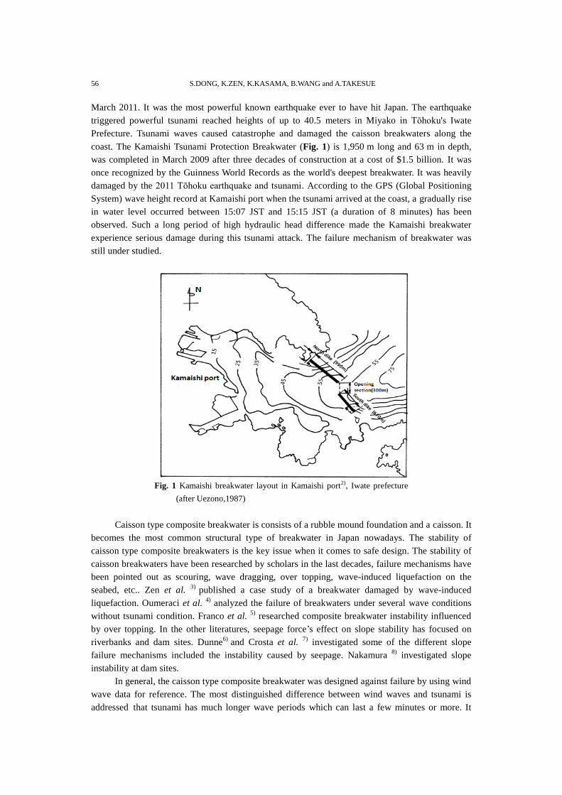
coast. The Kamaishi Tsunami Protection Breakwater (Fig. 1) is 1,950 m long and 63 m in depth,
was completed in March 2009 after three decades of construction at a cost of $1.5 billion. It was
once recognized by the Guinness World Records as the world's deepest breakwater. It was heavily
damaged by the 2011 Tōhoku earthquake and tsunami. According to the GPS (Global Positioning
System) wave height record at Kamaishi port when the tsunami arrived at the coast, a gradually rise
in water level occurred between 15:07 JST and 15:15 JST (a duration of 8 minutes) has been
observed. Such a long period of high hydraulic head difference made the Kamaishi breakwater
experience serious damage during this tsunami attack. The failure mechanism of breakwater was
still under studied.
Fig. 1 Kamaishi breakwater layout in Kamaishi port2), Iwate prefecture
(after Uezono,1987)
Caisson type composite breakwater is consists of a rubble mound foundation and a caisson. It
becomes the most common structural type of breakwater in Japan nowadays. The stability of
caisson type composite breakwaters is the key issue when it comes to safe design. The stability of
caisson breakwaters have been researched by scholars in the last decades, failure mechanisms have
been pointed out as scouring, wave dragging, over topping, wave-induced liquefaction on the
seabed, etc.. Zen et al. 3)
published a case study of a breakwater damaged by wave-induced
liquefaction. Oumeraci et al. 4)
analyzed the failure of breakwaters under several wave conditions
without tsunami condition. Franco et al. 5)
researched composite breakwater instability influenced
by over topping. In the other literatures, seepage force’s effect on slope stability has focused on
riverbanks and dam sites. Dunne6)
and Crosta et al. 7)
investigated some of the different slope
failure mechanisms included the instability caused by seepage. Nakamura 8)
investigated slope
instability at dam sites.
In general, the caisson type composite breakwater was designed against failure by using wind
wave data for reference. The most distinguished difference between wind waves and tsunami is
addressed that tsunami has much longer wave periods which can last a few minutes or more. It
Page 3
Theoretical and Experimental Study on Tsunami Induced Stability of Caisson Type Composite Breakwater 57
makes the large hydraulic head difference generated between the sea side and harbor side of
caisson. Hitachi et.al9)
studied the stability of armored stone considering the tsunami condition as
the steady flow. So far, few researches on the past failure events or theoretical analysis have
considered the stability of rubble mound beneath caisson influenced by seepage flow. It can be said
that under tsunami loading conditions, the seepage flow may play an important role on the stability
such as piping phenomena and reduction of bearing capacity in rubble mound beneath caisson.
Therefore, the purpose of this paper is to experimentally reproduce the failure induced by the
seepage flow in rubble mound beneath caisson and to explain the failure mechanism based on a
simple theoretical approach in order to make clear of the significance of seepage flow in the design
process of caisson type composite breakwaters against tsunami.
The section 4 of Kamaishi breakwater south dike, the deepest part in the whole breakwaters,
was chosen as the research section. The illustration of it is shown in Fig. 2.
Fig. 2 Cross section of Kamaishi breakwater’s southern dike, section 4.10)
From this study, a simplified failure criterion has been proposed to analyze the stability of the
mound element under seepage condition. Two kinds of laboratory experiments have been planned
to investigate the failure mechanism. Figure 3 shows the research procedures.
Fig. 3 Flow chart of stability analysis of caisson type composite breakwater.
Page 4
58 S.DONG, K.ZEN, K.KASAMA, B.WANG and A.TAKESUE
2. Theoretical Analysis on “Pop-out” Failure
Theoretical analysis is made by using Darcy’s law with the following assumptions: (1) the
rubble mound is fully saturated, homogeneous, and isotropic; (2) the flow is in steady state; (3)
the fluid is incompressible; and (4) the hydraulic head is constant. Such a phenomenon is
described by the Laplace equation:
2 2
2 2=0
H H
x y
(1)
Where H is the hydraulic head and (x, y) are the Cartesian coordinates.
A common method for solving this equations in soil mechanics is the graphical technique of
drawing flow nets where contour lines of hydraulic head and the stream function make a
curvilinear grid, allowing complex geometries to be solved approximately. Since an equivalent
amount of flow is passing through each element, the smallest squares in a flow net are located at
points where the flow is concentrated.
The water goes through every element in the flow net and the upward seepage force reduces
the effective force on the mound, resulting in lower mound shear strength. This paper adapted the
basic concept of the “pop-out” failure which has been proposed by Budhu et al.11)
in their study
on slope stability problem under seepage force influence while following a different definition of
the critical factor. The reason is that this case study is an underwater slope in a fully saturated
condition but the former cases were slopes with free surfaces. The direction of flow follows the
flow-line, and the seepage force direction can be described as the same direction. Acceptability
criteria for the damage of a breakwater are represented as the following: to simplify the process of
mound element failure by seepage force, a criteria equation is given as:
cos w
H
N a
(2)
where is the rubble mound’s effective unit weight, is the slope angle, w is the unit weight
of water,ΔH is the hydraulic head difference between the seaside and the harbor side, N is the
number of equipotential line, and a is the length of the unit square inside the flow net as shown in
Fig. 4.
Fig. 4 Force decompose sketch of unite square on surface of rubble mound.
Page 5
Theoretical and Experimental Study on Tsunami Induced Stability of Caisson Type Composite Breakwater 59
The critical factor of stability is defined as Fa and is shown in Eq. 3
cos
/ ( )a
w
FH N a
(3)
When Fa <1, the unit square inside the rubble mound becomes instable.
Procedure of flow net solution:
① Illustrate the flow net;
② Get the length of “a” of each element along the sloped surface of the rubble mound (at the
turning point of the crest, get the direct value of “a” instead of adding both lengths);
③ Calculate the value of Fa with Equation 3 with known slope angle, effective unit weight and
hydraulic head difference;
④ Find the location where Fa is less than 1 which can indicate the point of failure on the rubble
mound.
Fig. 5 Flow net illustration of Kamaishi breakwater.
Figure 5 applies the Kamaishi breakwater case data from the tsunami event and uses the
theoretical method of calculation in order to find the failure area. The dimension data of Kamaishi
breakwater were described as following: the caisson was 26 meters in width and 20 meters in
height, slope angle of rubble mound was 27 degrees with the slope ratio equals to 1:2. The height
of rubble mound was 43 meters. Hydraulic head difference from sea side towards harbor side was
13.64meters.The calculated data are given as w =1 N/m3; =0.8 N/ m
3; θ =27°; N=14;
ΔH=13m and the value of “a” is obtained from Fig. 5.
In order to get a deeper understanding of the influence of seepage flow on the stability of the
rubble mound, parametric studies were carried out to investigate the relationship between slope
angle and the value of “a” as well as the relationship between hydraulic head difference and the
value of “a”. The results were shown in Fig. 6 and Fig. 7. In these two figures, the vertical axis
represents the value of calculated Fa. The solid red lines shown in Fig. 6 and Fig.7 imply that when
Fa is equal to 1, the values of “a” above solid red line were the unstable areas. Therefore, the
critical value of Fa can be obtained from the graphs. Major trends of the development of these
values are concluded as: the value of Fa decreases when slope angle increases under the condition
of constant hydraulic head difference. On the other hand, the stability of rubble decreases when
hydraulic head difference increases for the same breakwater.
Furthermore, detailed results indicate that the areas of instability occur within 1.2m off the
caisson toe on the harbor side along the rubble mound crest. According to Harry’s 12)
study on the
seepage force induced instability problem, this reasonably small area might be the triggering factor
Page 6
60 S.DONG, K.ZEN, K.KASAMA, B.WANG and A.TAKESUE
for the entire failure of rubble mound or it might play an integral role in the global stability when
combined with wave forces. Therefore, two types of laboratory experiments were carried out to
investigate the influence of seepage on the stability of caisson type breakwaters.
3. Experiment on Seepage Flow-induced Instability
3.1 Outlines of experiment
A model for laboratory experiment was established by simulating the Kamaishi breakwater’s
southern dike, section 4 at a scale of 1/100. The rubble mound material is crushed stones of which
Dmin is 2mm, Dmax is 35mm and D50 is 10mm. The dimensions of caisson are 195mm in height,
185mm in length and 190mm in width. The caisson was filled with sand. The density of sand is
2.03 g/cm3. In order to reproduce the effects of hydraulic head difference on caisson type
breakwaters during tsunami waves, three pumps were introduced to create hydraulic head
difference. The experiment layout was shown in Fig. 8. The cross section view of the caisson type
composite breakwater located in water tank is shown in Fig.8 as (a) cross section. A pump system
was established to control the hydraulic head difference from the sea side towards the harbor side
of the physical model. Legend in Fig.8 shows the installations of measuring equipment. The plan
view of the physical model is presented in Fig.8 as (b) plan view. All the equipments were set on
the caisson which was located in the middle of tank. The two side caisson boxes among three
caisson boxes were placed to avoid the friction effect along tank walls. All the dimensions are
shown in Fig. 8.
The objective of the experiment is to observe the failure phenomena when hydraulic head
difference is created. Water pressure gauges were embedded in the rubble mound to investigate the
variation of pore pressure during the experiment, and wave height sensors were set on both sides of
the caisson as shown in Fig. 9. The x-y coordinate was used as shown in Fig.9 and initial point was
also given in the graph for later coordinate reference. The experimental data were collected
electronically and processed by computer.
It is very important to observe the area of instability along the rubble mound surface when
hydraulic head difference is created. Video recording of the experiments is applied.
0.4
0.6
0.8
1
1.2
0.4 0.5 0.6 0.7 0.8 0.9 1 1.1
45 degree
35 degree
27 degree
a(m)
Fa
0.2
0.4
0.6
0.8
1
1.2
0.4 0.5 0.6 0.7 0.8 0.9 1 1.1
13m16m20m
Fa
a(m)
Fig. 6 Relationship between a and Fa with different
slope angle (same hydraulic head difference).
Fig. 7 Relationship between a and Fa with different
hydraulic head differences (same slope angle).
Page 7
Theoretical and Experimental Study on Tsunami Induced Stability of Caisson Type Composite Breakwater 61
Fig. 9 Experiment equipments settings.
3.2 Results and discussions
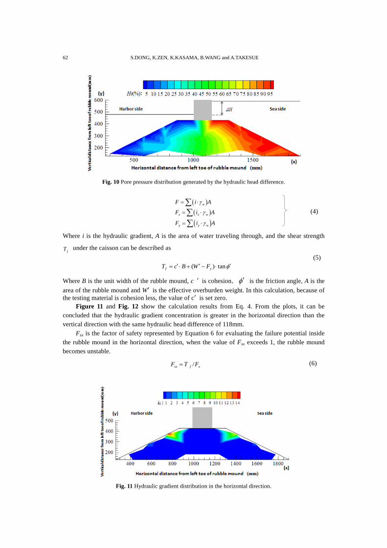
Data from the above experiments were processed and utilized for calculation. In Fig.10, only
the upper part of rubble mound in Fig.9 where the pore pressure gauges were installed area is
demonstrated. The starting of x-axis is set 300mm from the left toe of rubble mound and y-axis is
set 130mm from the left toe of rubble mound. From the pore pressure data obtained in the
experiment, the hydraulic gradient distribution was illustrated as in Fig. 10 by Tecplot software14)
.
It represents that the hydraulic head difference generates great pore pressure from the seaside
towards the harbor side, which might cause the instability of rubble mound.
In order to understand the influence of seepage force on the stability of the rubble mound,
failure criteria are applied to the following analysis. The seepage force F can be decomposed into
horizontal and vertical components by the following equations, and the influence of seepage force
in each direction can be evaluated by the following equations.
Fig. 8 Layout of experiment model in water tank (script).
Page 8
62 S.DONG, K.ZEN, K.KASAMA, B.WANG and A.TAKESUE
Fig. 10 Pore pressure distribution generated by the hydraulic head difference.
w
x x w
y y w
F i A
F i A
F i A
Where i is the hydraulic gradient, A is the area of water traveling through, and the shear strength
fT under the caisson can be described as
( ) tanf yT c B W F
Where B is the unit width of the rubble mound, c is cohesion, is the friction angle, A is the
area of the rubble mound and W is the effective overburden weight. In this calculation, because of
the testing material is cohesion less, the value of c is set zero.
Figure 11 and Fig. 12 show the calculation results from Eq. 4. From the plots, it can be
concluded that the hydraulic gradient concentration is greater in the horizontal direction than the
vertical direction with the same hydraulic head difference of 118mm.
Fsx is the factor of safety represented by Equation 6 for evaluating the failure potential inside
the rubble mound in the horizontal direction, when the value of Fsx exceeds 1, the rubble mound
becomes unstable.
/sx f xF T F (6)
Fig. 11 Hydraulic gradient distribution in the horizontal direction.
(4)
(5)
Page 9
Theoretical and Experimental Study on Tsunami Induced Stability of Caisson Type Composite Breakwater 63
Fig. 12 Hydraulic gradient distribution in the vertical direction.
Fig. 13 Fxs calculated by failure criteria.
The calculation result is shown in Fig.13. It can be seen that when hydraulic head difference
is 118mm, the rubble mound slope surface area with depth of 62.3mm has failure potential. This
corresponds 6.2 m at full scale. However, in the laboratory modeling tests, the “pop out” failure due
to seepage forces is hardly found. Although the hydraulic gradient shows a concentration on the
surface of the rubble mound and Fxs have been dramatically reduced, it is less likely that the
excessive pore-pressure (seepage force) can cause the catastrophic failure at hydraulic head
difference of 118mm. This leads to the hypothesis that the combination of seepage force with
downstream surface erosion caused by overtopping might be the major cause of caisson type
breakwater failure. Detailed investigation and experimentation focused on this failure mechanism
should be carried out. Besides the suggestions given above, the lack of failure observed under these
wave conditions might be due to the selection of rubble mound material in this experiment. Finer
rocks with smaller diameters should be tested in later experiments.
Even though the pore pressure test did not reproduce the failure, the seepage force effects on
the stability of caisson type breakwaters still need to be investigated in more detail with respect to
the bearing capacity of the rubble mound. The experiments on rubble mound bearing capacity are
presented below.
Page 10
64 S.DONG, K.ZEN, K.KASAMA, B.WANG and A.TAKESUE
4. Experiment on Bearing Capacity
4.1 Outlines of loading test
In order to find out the effects of seepage flow on the bearing capacity of the rubble mound
during tsunami, the following tests have been carried out. The relationship between loading
pressures and the displacement of caisson was observed in this experiment. The loading procedures
were given as follows: firstly put loads in the center of caisson top, and then measured the
displacement of caisson under different hydraulic head differences. Hydraulic head differences
were set as 0mm, 50mm, 90mm and 118mm. Three pumps were used to adjust the hydraulic head
difference from sea side to harbor side. Displacement data were collected for the later calculation
and analysis in the following contexts.
4.2 Test results and discussions
When weight was loaded on the caisson, displacements of the caisson were observed, and
these displacement data were collected at certain hydraulic head difference. The settlement values
have been compared in Fig. 14.
0
5
10
15
20
0 5 10 15 20 25 30
No
rmal
ized
set
tlem
ent
(%
)
Loading pressure (KN/m2)
hydraulic
head difference
0mm
118mm
90mm
50mm
Fig. 14 Relationship between loading pressure and normalized
settlement of caisson.
The settlement of caisson due to weight loading shows a trend: when loading increases, the
settlement becomes larger. As expected, the larger hydraulic head difference influenced the bearing
capacity of the rubble mound. The curves show a clear tendency that the settlement increases about
50% when hydraulic head difference increases from 0mm to 118mm. It is indicated that the
displacement of caisson becomes larger when the hydraulic head difference becomes larger. It
might trigger entire failure of rubble mound at a certain value of hydraulic gradient. In other words,
it is found that the seepage force contributes to reduce the bearing capacity of rubble mound.
Figure 15 shows the relationship between the caisson incline angle and weight loading. When
the hydraulic head difference stays constant, the loading value reaches 15 KN/m2. The settlement of
the caisson develops significantly when the loading increases to 25 KN/m2, and the biggest
hydraulic head difference (118mm) creates the largest settlement. In other words, the increase of
hydraulic head difference has a negative influence on the stability of caisson and with such a big
displacement.
Page 11
Theoretical and Experimental Study on Tsunami Induced Stability of Caisson Type Composite Breakwater 65
The inclinations were also calculated from this experiment and from the results in Fig. 15.
The deformation of the rubble mound becomes significant when hydraulic head difference
increases, in this case to 118mm, and the caisson is prone to be less stable when hydraulic head
difference is large.
0
2
4
6
80 5 10 15 20 25 30
Incl
inat
ion o
f ca
isso
n t
ow
ards
to s
ea s
ide
(x10
3 d
eg.)
Loading pressure (KN/m2)
118mm
90mm
50mm
0mm
hydraulic head difference
Fig. 15 Relationship between loading pressure and
inclination of caisson towards to sea side.
The analysis of the results in Fig. 14 and Fig. 15 show that pore pressure generated by seepage
flow brings the decreases of effective stress which may cause instability of the caisson. Therefore,
it is necessary to calculate the entire stability of rubble mound to analyze the influence of seepage
flow on the caisson type breakwaters.
5. Circular Failure Analysis
According to the existing calculation methods15)
for the bearing capacity of rubble mound, the
modified Felleinus method was selected to evaluate the circular failure.
Fig. 16 Model of circular failure analysis.
The graphical viewing of computed details has led to a greater understanding of the method,
Page 12
66 S.DONG, K.ZEN, K.KASAMA, B.WANG and A.TAKESUE
as illustrated in Fig. 16. It shows the calculation of characteristics of the slip surface on the rubble
mound with mathematical equations given as follows:
( )cos sin sin cos tani i w i x i y iR P W H F F
( )sin cos cos sini i w i x i yS P W H F F
1 1
/
n n
s i i
i i
F R S
where P is the weight of the caisson itself, Hw is the horizontal water static load, Fx and Fy are the
decomposed seepage force in the horizontal and vertical components respectively, the subscript i
is the number of each slice of potential failure, i is the angle of slice slip surface towards the
horizontal direction, W is the effective weight of the rubble mound, Ri is the resistance force and
Si is the shear strength. In these equations, when Fs is larger than one, the caisson is stable.
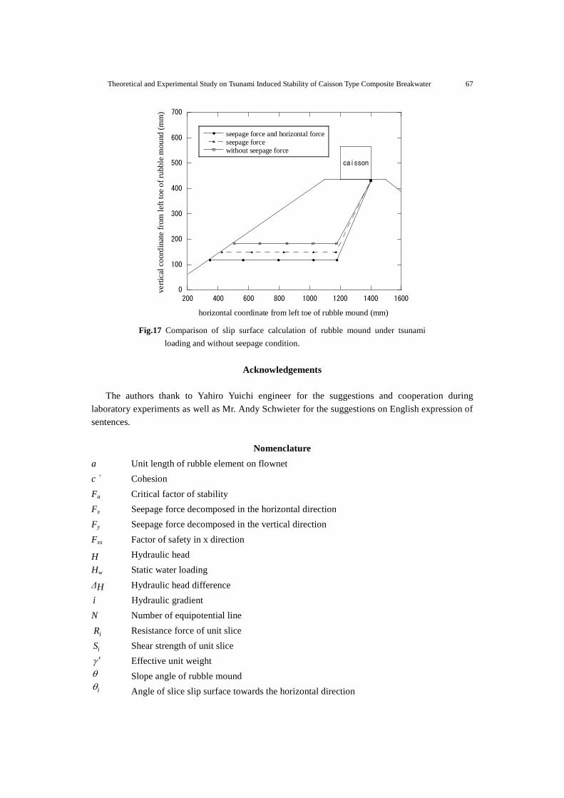
In order to get a clear understanding of the seepage force influence on caisson stability,
further calculations were done and the results are shown in Fig.17. The locations of slip surface
indicate the influence of seepage flow in rubble mound. By comparing with three conditions, the
results show that the slip surface which induced by static horizontal force and seepage force is the
shallowest line among three lines, the shear outlet of slip surface moved from the bottom of rubble
mound towards the top of rubble mound significantly compared with conditions with seepage flow
and without seepage flow in rubble mound.
6. Conclusions
The paper applies a fundamental theoretical approach and experimental approach to analyze
the stability of caisson type composite breakwaters under tsunami condition.
Five conclusions are drawn from the study: (1) by flow-net graphic solution analysis, it can
be concluded that when wave height increases, the area of instability in the rubble mound enlarges
and when the rubble mound slope angle increases, the rubble mound becomes unstable due to
seepage force, (2) A failure criteria is applied to analysis the stability of the rubble mound beneath
caisson and seepage force acts in horizontal direction is emphasized in the data analysis, (3) pore
pressure data were collected from experiment and calculated based on the proposed failure criteria.
The results indicate the unstable area along the rubble mound, although failure was not observed in
the real experiment, (4) the experiment results of the bearing capacity show the bearing capacity of
rubble mound decreased by about 50% when affected by the horizontal seepage force in
comparison with the condition without seepage flow, (5) from the slip surface calculation by the
modified Felleinus method, the potential slip surface in the rubble mound under developed
shallower when influenced by seepage force and horizontal loading from hydraulic head difference
on sea side.
In conclusion, it can be said that when consider the composite breakwater design against
tsunami, the seepage force should be taken into account as a significant influential factor.
(7)
Page 13
Theoretical and Experimental Study on Tsunami Induced Stability of Caisson Type Composite Breakwater 67
0
100
200
300
400
500
600
700
200 400 600 800 1000 1200 1400 1600
seepage force and horizontal forceseepage forcewithout seepage force
vert
ical
co
ord
inat
e fr
om
lef
t to
e o
f ru
bb
le m
ou
nd
(m
m)
horizontal coordinate from left toe of rubble mound (mm)
caisson
Fig.17 Comparison of slip surface calculation of rubble mound under tsunami
loading and without seepage condition.
Acknowledgements
The authors thank to Yahiro Yuichi engineer for the suggestions and cooperation during
laboratory experiments as well as Mr. Andy Schwieter for the suggestions on English expression of
sentences.
Nomenclature
a Unit length of rubble element on flownet
c΄ Cohesion
Fa Critical factor of stability
Fx Seepage force decomposed in the horizontal direction
Fy Seepage force decomposed in the vertical direction
Fxs Factor of safety in x direction
H Hydraulic head
Hw Static water loading
ΔH Hydraulic head difference
i Hydraulic gradient
N Number of equipotential line
iR Resistance force of unit slice
iS Shear strength of unit slice
Effective unit weight
Slope angle of rubble mound
i Angle of slice slip surface towards the horizontal direction
Page 14
68 S.DONG, K.ZEN, K.KASAMA, B.WANG and A.TAKESUE
References
1) http://en.wikipedia.org/wiki/2011_Tohoku_earthquake_and_tsunami, Wikipedia, the free
encyclopedia, 1st May, (2012).
2) A. Uezono and H. Odani; Rubble Mound Construction and Design of Deep Water
Breakwater-A Case Study on Kamaishi Breakwater, Lecture of Japanese Geotechnical Society,
pp.69-76, (1987), [in Japanese].
3) K. Zen, et al., A Case Study of the Wave-induced Liquefaction of Sand Layers under Damaged
Breakwater, 3rd Marine Geotechnical Engineering, Pro. Int. Conf. Newfoundland, Canada,
June 11-13, 1986, pp.505-520, (1985).
4) H. Oumeraci and A. Kortenhaus; Analysis of the Dynamic Response of Caisson Breakwater,
Coastal Engineering, 22, pp.159-183, (1994).
5) L. Franco, et al., Wave Overtopping on Vertical and Composite Breakwaters, 24th Coastal
Engineering, Pro. Int. Conf. Kobe, Japan, October 23-28, pp.1-16, (1994).
6) T. Dunne; Hydrology Mechanics and Geomorphic Implications of Erosion by Subsurface Flow,
Geology Society American, Special Paper 252: 1-28, (1990).
7) G. Crosta and C. Prisco; On Slope Instability Induced by Seepage Erosion, Canadian
Geotechnical Journal, 36, pp.1056-1073, (1999).
8) K. Nakamura; On Reservoir Landslide, Bulletin of Soil and Water Conservation, 10 (1),
pp.53-64, (1990), [in Chinese].
9) S. Hitachi, et al.; Experimental Studies on Tsunami Flow and Armor Block Stability for the
Design of a Tsunami Protection Breakwater in Kamaishi Bay, Coastal Development Institute of
Technology, Vol.1, pp765-783, (1994).
10) Urgent Survey for 2011 Great East Japan Earthquake and Tsunami Disaster in Ports and Coasts,
Report of the Port and Harbor Research Institute, Ministry of Transport, pp.157-160,
(2011 ),[in Japanese].
11) M. Budhu and R. Gobin; Slope Stability from Groundwater Seepage, Journal of Hydraulic
Engineering-ASCE, 122 (7), pp.415-417, (1996).
12) R. Harry, Seepage, Drainage and Flow Nets, 3rd edition, Wiley-Interscience, pp.94-96, (1997).
13) T. Imase, et al.; Instability of Caisson-type Breakwater Due to Seepage of Tsunami into Rubble
Mound and Seabed, Journal of Japan Society of Civil Engineers, Ser. B2 (Coastal Engineering),
Vol. 67, No. 2, pp.I_551-I_555, (2011), [in Japanese].
14) Tecplot software manuals, Tecplot® Focus™, (2006).
15) M. Kobayashi, et al.; Bearing Capacity of a Rubble Mound Supporting a Gravity Structure,
Report of the Port and Harbor Research Institution, Vol.26, No.5, pp.215-252, (1987).