---------------------------------------------------------------------***---------------------------------------------------------------------Abstract - Power production and grid stability have become key problems in the last decade. The high penetration of huge capacity wind production into the electric power grid has given rise to serious issue about their authority on the dynamic behavior of power systems. The Low-Voltage Ride-Through (LVRT) capability of wind turbines during grid faults is one of the main requirements to make sure the stability in the power grid during transients. The doubly-fed induction generators (DFIGs) offer quite a lot of advantages when utilized in wind turbines, but debate about their LVRT capabilities are limited. This paper presents a complete study of the LVRT of grid-connected DFIG-based wind turbines. It provides a comprehensive investigation of the dynamic behavior and the transient characteristics of DFIGs during symmetrical and asymmetrical grid voltage dips. A comprehensive theoretical study supported by MATLAB simulations is provided.
Key Words: Wind power production, Doubly-fed induction generator (DFIG), Grid fault, Low-Voltage Ride-Through (LVRT), Power converters.
INTRODUCTION
In recent time, there has been an enormous increase in the global demand for energy as a result of not only the population growth, but also the industrial development. Therefore, the rise in utilization of traditional fossil fuels has led to a lot of serious problems such as energy shortages, global warming, pollution and the shortfall of traditional fossil energy sources. These factors are motivating the development of renewable energy technologies [1]-[3]. Wind power is considered to be the most capable alternative energy in the near future. As renewable energy sources grow in fame, wind power is presently one of the fastest rising renewable sources of electrical energy. By the end of 2015, the worldwide total installed electricity generation capacity from wind power amounted to 432,883 MW, raise of 17% compared to the earlier year [2].
With the enlarged existence of wind energy into the power system over the recent time, a severe alarm
about its influence on the dynamic behavior of the electric power network has appeared [3]. Therefore, it becomes vital to entail grid-connected wind turbines to have a comparable behavior as the conventional power plants and to sustain the power network during normal and abnormal grid conditions. This made many countries to develop precise grid codes for operation and grid integration of wind turbines. Among these grid codes, the two main issues are of particular alarm for engineers in the vicinity of power and energy: a) active and reactive power control in steady state conditions and b) Low-Voltage Ride-Through (LVRT) capability during grid faults and Fault Ride-Through (FRT) capability [3].
The Doubly-Fed Induction Generator (DFIG)-based wind turbine has turn out to be one of the most encouraging choices in wind power production. This is due to the high-flying advantages that it has compared to the other energy conversion systems that presently exist in the market. Nevertheless, the dynamic response of the DFIG to the grid voltage transients is the major serious problem [4].
DFIG-based wind turbines are sensitive to voltage sags at the time of grid faults. This is due to the back-back power converters that tie the rotor of the generator to the power grid. Faults in the power system, yet far away from the location of the turbine, can root an abrupt decrease of the grid voltage which tends to an over-voltage in the DC bus and an over-current in the rotor circuit of the generator [6]-[8]. With no protection scheme, this can lead to the dent of the power converters. Additionally, it might also boost the speed of the turbine above the rated limits if not suitably designed, which will intimidate the safe operation of the turbine [6]-[9]. Therefore, the LVRT capability of DFIG-based wind turbines at the time of grid faults are intensively examined in order to afford appropriate solutions that can protect the turbine during abnormal conditions of the grid.
The aim of this paper is to study the dynamic behavior of grid-connected DFIG-based wind turbines under LVRT environment. Comprehensive analysis of the LVRT of DFIGs, together with the voltage sag profile, transient characteristics and the behavior of the DFIG at
International Research Journal of Engineering and Technology (IRJET) e-ISSN: 2395-0056
Volume: 03 Issue: 10 | Oct -2016 www.irjet.net p-ISSN: 2395-0072
the moments of voltage sag as well as the consequent voltage recovery, is examined. A simplified dynamic model of the DFIG is used to examine the performance of the wind energy generation system under the influence of symmetrical and asymmetrical grid faults.
GRID CODE REQUIREMENTS FOR WIND TURBINES
The operation and grid connection necessities for wind turbines differ between utilities around the world, but some requirements are common to most of them. A few of these requirements are as follows [3]-[4].
1. Voltage and frequency operating ranges: The wind turbines are mandatory to stay associated with the grid and work within typical grid voltage and frequency ranges.
2. Active and reactive power control: Grid codes entail wind farms to offer a certain control of the output active power to ensure a steady frequency in the power system. Wind farms are also essential to control their output reactive power in order to sustain the reactive power balance and the power factor at the Point Common Coupling (PCC) within the preferred range.
3. Voltage and frequency control: Grid codes call for each wind turbine to manage its own terminal voltage to a stable value by means of an Automatic Voltage Regulator (AVR). They also require wind farms to offer frequency regulation ability to maintain the preferred network frequency.
4. Low-Voltage Ride-Through (LVRT): During grid faults, wind turbines are essential to stay connected to the grid for a definite amount of time before being acceptable to disconnect. In addition, wind turbines are required to sustain the grid voltage during both symmetrical and asymmetrical grid voltage sags by means of reactive power compensation.
5. High-Voltage Ride-Through (HVRT): HVRT grid code states that wind turbines should be able to stay connected to the grid for a definite amount of time in the event of grid voltage goes over its upper limit value.
6. Power quality capability: Wind farms are required to deliver power with a desired quality, e.g., maintaining constant voltage/current harmonics within preferred range, etc.
Grid codes differ appreciably from country to country and from power system to power system. These differences depend on the degree of wind power access and the sturdiness of the power network. Low voltage ride through (LVRT) means that when power grid fault or voltage dip by interruption on the integration net of generators, in certain range of voltage dip, wind power generator can keep continuous parallel operation and offer reactive power to power grid until the improvement. Voltage dip will create a sequence of transient process of
wind power generator. It would affect the safe operation of generator and the whole control system. Thus, it is necessary that putting forward the technical requirements of the generator's LVRT ability. Fig (1) shows the typical requirement of LVRT.
1. When voltage drop to 15 percent of the rated voltage on the integration net, the wind farms can stay parallel operation for 0.6265s.
2. Since voltage dip, the wind power generator must keep integration, if the integration voltage can come back up to 90 percent of the rated voltage in 3 seconds.
It is acceptable that wind power generator depart from integration, only when the voltage's value and time on the integration net is both lesser than the curve shown in the graph. But if the voltage is above the curve, wind power generator must keep integration, and provide support to make the voltage and power to meet the requirements until the integration voltage recover.
Time (s)
Fig 1: Typical Low voltage ride through requirement.
DFIG-BASED WIND POWER GENERATION SYSTEM
At present, commercial wind turbines mix and match a variety of pioneering concepts with verified technologies for both power electronics and generators. Various wind turbine configurations can be obtained by combining an induction or synchronous generator with a full-scale or partial-scale power converter [6]-[10]. The variable speed wind turbine generators are categorized by two major types: direct drive Permanent Magnet Synchronous Generators (PMSGs) and DFIGs. Typical connection of DFIG based wind power generation system is shown in figure (2):
The DFIG is a perfect answer for systems with limited variable-speed range, e.g. ±30% of the synchronous speed. The reason is that the power electronic converter has to handle a part (20–30%) of the total generated power compared to the direct drive PMSG-based wind turbines. As a result, the operational losses and the equipment cost of the power converter can be appreciably reduced compared to a system where the converter has to handle the total generated power [5], [10].
International Research Journal of Engineering and Technology (IRJET) e-ISSN: 2395-0056
Volume: 03 Issue: 10 | Oct -2016 www.irjet.net p-ISSN: 2395-0072
Fig 2: Wind turbine configuration of the DFIG-based wind turbine with a gearbox.
The back-to-back power converter in the DFIG
system consists of two converters, i.e., Grid -Side Converter (GSC) and Rotor-Side Converter (RSC), which are connected back-to-back by a dc-link. Between the two converters, a dc- link capacitor is positioned as energy storage in order to maintain the voltage variations (or ripple) in the dc-link voltage small. With the RSC, it is feasible to control the torque, the speed of DFIG as well as the active and reactive powers at the stator terminals. The main purpose of the GSC is to keep the dc-link voltage constant. It can also be used to manage the reactive power flowing from or to the power grid [10].
DYNAMIC MODELING OF DFIG
The operating principle of the variable speed DFIG can be handily analyzed by the classical rotating field theory with the well-known Clarke and Park transformations [11]. Since the DFIG can be considered as a traditional induction generator with non-zero voltage, its dynamic equivalent circuit in the dq-synchronous reference frame can be modeled as shown in Fig (3):
Lls Rs ωsλqs Llr Rr (ωs-ωr) λqr
ids idm idr
vds Lm vdr
Lls Rs ωsλds Llr Rr (ωs-ωr) λdr
iqs iqm iqr
vqs Lm vqr
Fig 3: Equivalent circuit of the DFIG in the dq-synchronous reference frame.
The full-order dynamic model of DFIG in the synchronous rotating reference frame can be described as given [11]-[12]:
where the subscripts “r” and “s” represent the rotor and stator sides, rs and rr are resistances of the stator and rotor windings, Lm is the magnetizing inductance, Lls and Llr are the stator and rotor leakage inductances, λs and λr are the stator and rotor magnetic flux linkages, vs and is are the stator voltage and current, vr and ir are the rotor voltage and current, ωe is the electrical angular velocity of the synchronous reference frame, and ωr is the electrical angular velocity of the rotor.
It is shown in [12] that a number of simplifications can be made to the system given in (1) since the DFIG-based wind turbine is considered to be component of an electrical system where other components such as the power converters and the electrical networks are involved.
First, the stator flux-oriented synchronous reference frame, where the q-axis is aligned to the positive-sequence stator flux, is applied to the DFIG full-order model given in (1). By assuming stator resistance to be negligible, the rotor voltage equations can be expressed as [13]:
(
)
(2)
(
)
(3)
where
.
Equations (2) and (3) holds for both steady-state and transient conditions. It gives a direct relationship between the instantaneous values of the stator and rotor
GRID
CROWBAR
DFIG
GEARBOX
PWM RECTIFIER PWM INVERTER
DC LINK
STEP-UP TRANSFORMER
WIND
International Research Journal of Engineering and Technology (IRJET) e-ISSN: 2395-0056
Volume: 03 Issue: 10 | Oct -2016 www.irjet.net p-ISSN: 2395-0072
dq-voltages to the dq rotor currents. The stator flux is usually estimated by integrating the stator voltage. During the steady-state conditions, by neglecting rr and Lr and approximating Lm/Ls = 1, the RSC AC-side output voltage is nearly sVs, where Vs is the magnitude of the steady-state stator voltage.
If sudden voltage sag occurs at the stator terminals, the required rotor terminal voltage could be directly generated from (2) and (3) such that the rotor current will not be affected and remains unaffected. On the other hand, since the RSC rating is restricted and cannot generate the necessary rotor voltage, a large transient in the rotor current will appear during grid voltage sags.
During voltage sag, when the rotor current is kept constant, the stator current tends to oscillate with the stator frequency (ωs) and the oscillation damping depends on the stator time constant (τs). At the time of asymmetrical faults, a negative sequence will appear and also force oscillation but with a frequency equal to (2ωs) [7], [12], [14] and [15].
It is also confirmed in [16] that the direct relationships between the stator flux linkage, rotor current and stator voltage, using the stator voltage-oriented synchronous reference frame (vqs = 0 and vs = vds), can be derived as:
⁄
⁄ ⁄
⁄ ⁄
Equations (4) and (5) show that the stator flux linkages depends on the stator voltage and rotor current, explaining the behavior of the DFIG at the time of grid faults. If voltage sag happens at the stator terminals, when the rotor current is kept constant, the stator flux tends to oscillate with the stator frequency (ωs) and the oscillation damping depends on the stator time constant (τs). At the time of asymmetrical faults, a negative sequence will emerge and also force oscillations but with a frequency equal to (2ωs) [12], [15] and [16].
TRANSIENT ANALYSIS OF THE DFIG MAGNETIC
FLUX DURING FRID FAULTS
A. Symmetrical Faults
A voltage dip is a sudden drop of one or more voltage phases. If the drop in all the three phases is equal then such a dip is called Symmetrical or Balanced dip. Even though the analysis can be applied to any type of voltage dip, here the analysis is due to the abrupt dip i.e.,
voltage drops at time t = 0 from its initial value, pre to its final value, final.
In real systems, the voltages drops with a particular derivative, which depends on the grid and the characteristics of the fault that has caused the voltage dip.
During the total voltage dip the zero voltage will appears at the terminals of the machine which might be caused by a short circuit fault at the grid. Here, the Rotor is considered to be open circuited. In the steady state, the flux is proportional to the stator voltage and hence if the dip is long enough the machine will demagnetize completely. Nevertheless, the flux cannot be discontinuous as it is a state variable. Besides, the flux evolves from its initial value prefault to zero, resulting in a transient emf induced in the rotor terminals.
The stator flux can be calculated from the dynamic expression of the stator,
In case of a total voltage dip, Vs = 0.
where is the initial value of the flux and τs = Ls/Rs is the
time constant of the stator. The value of can be
calculated by considering the flux just before and after the Dip. The flux during the dip doesn’t rotate and is fixed with the stator.
Fig (4): Stator flux trajectory during a total voltage dip.
-1.5 -1 -0.5 0 0.5 1 1.5-1.5
-1
-0.5
0
0.5
1
1.5
flux, alpha axis ( p.u )
flux,
beta
axis
( p
.u )
Steady state flux
Final flux
Voltage dip start
International Research Journal of Engineering and Technology (IRJET) e-ISSN: 2395-0056
Volume: 03 Issue: 10 | Oct -2016 www.irjet.net p-ISSN: 2395-0072
The flux which was rotating at the grid frequency before the dip, freezes during the dip and decays exponentially from its initial value to zero with the time constant of the stator. Fig (4) shows the trajectory of the space vector before and during the dip.
The stator currents can be obtained before and during the dip considering no current in the rotor and is given as
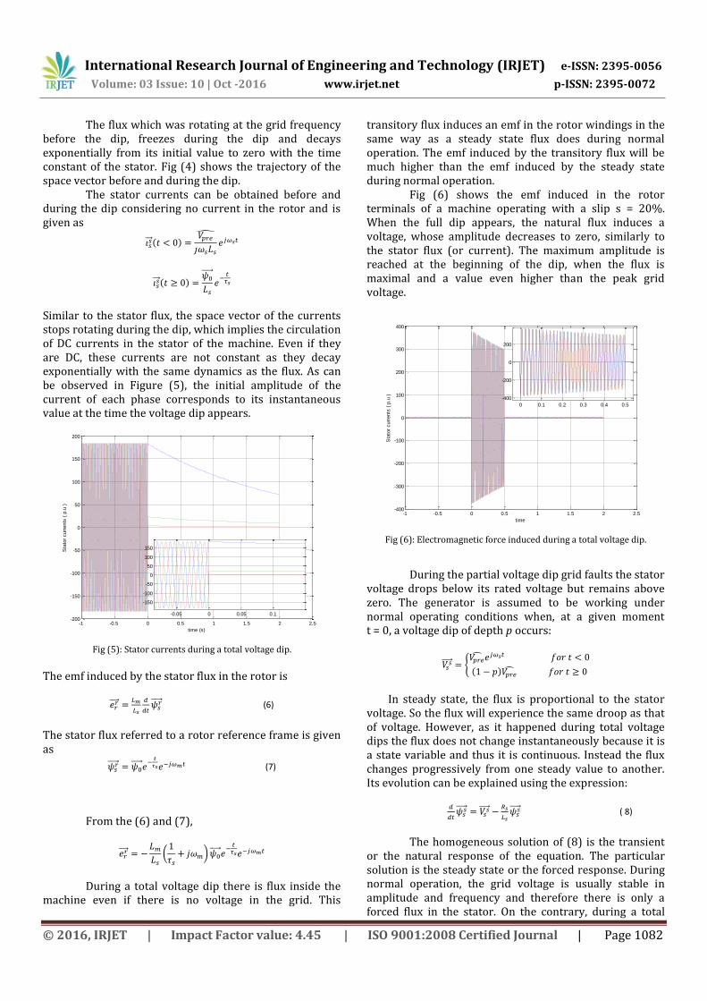
Similar to the stator flux, the space vector of the currents stops rotating during the dip, which implies the circulation of DC currents in the stator of the machine. Even if they are DC, these currents are not constant as they decay exponentially with the same dynamics as the flux. As can be observed in Figure (5), the initial amplitude of the current of each phase corresponds to its instantaneous value at the time the voltage dip appears.
Fig (5): Stator currents during a total voltage dip.
The emf induced by the stator flux in the rotor is
(6)
The stator flux referred to a rotor reference frame is given as
(7)
From the (6) and (7),
(
)
During a total voltage dip there is flux inside the machine even if there is no voltage in the grid. This
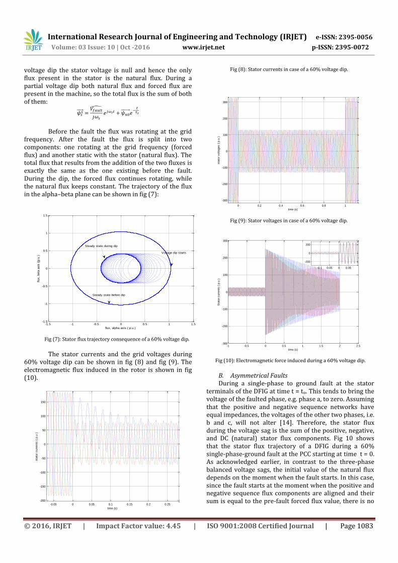
transitory flux induces an emf in the rotor windings in the same way as a steady state flux does during normal operation. The emf induced by the transitory flux will be much higher than the emf induced by the steady state during normal operation.
Fig (6) shows the emf induced in the rotor terminals of a machine operating with a slip s = 20%. When the full dip appears, the natural flux induces a voltage, whose amplitude decreases to zero, similarly to the stator flux (or current). The maximum amplitude is reached at the beginning of the dip, when the flux is maximal and a value even higher than the peak grid voltage.
Fig (6): Electromagnetic force induced during a total voltage dip.
During the partial voltage dip grid faults the stator voltage drops below its rated voltage but remains above zero. The generator is assumed to be working under normal operating conditions when, at a given moment t = 0, a voltage dip of depth p occurs:
{
In steady state, the flux is proportional to the stator voltage. So the flux will experience the same droop as that of voltage. However, as it happened during total voltage dips the flux does not change instantaneously because it is a state variable and thus it is continuous. Instead the flux changes progressively from one steady value to another. Its evolution can be explained using the expression:
( 8)
The homogeneous solution of (8) is the transient or the natural response of the equation. The particular solution is the steady state or the forced response. During normal operation, the grid voltage is usually stable in amplitude and frequency and therefore there is only a forced flux in the stator. On the contrary, during a total
-1 -0.5 0 0.5 1 1.5 2 2.5-200
-150
-100
-50
0
50
100
150
200
time (s)
Sta
tor
curr
ents
( p
.u )
-0.05 0 0.05 0.1
-150
-100
-50
0
50
100
150
-1 -0.5 0 0.5 1 1.5 2 2.5-400
-300
-200
-100
0
100
200
300
400
time
Sta
tor
curr
ents
( p
.u )
0 0.1 0.2 0.3 0.4 0.5
-400
-200
0
200
International Research Journal of Engineering and Technology (IRJET) e-ISSN: 2395-0056
Volume: 03 Issue: 10 | Oct -2016 www.irjet.net p-ISSN: 2395-0072
voltage dip the stator voltage is null and hence the only flux present in the stator is the natural flux. During a partial voltage dip both natural flux and forced flux are present in the machine, so the total flux is the sum of both of them:
Before the fault the flux was rotating at the grid frequency. After the fault the flux is split into two components: one rotating at the grid frequency (forced flux) and another static with the stator (natural flux). The total flux that results from the addition of the two fluxes is exactly the same as the one existing before the fault. During the dip, the forced flux continues rotating, while the natural flux keeps constant. The trajectory of the flux in the alpha–beta plane can be shown in fig (7):
Fig (7): Stator flux trajectory consequence of a 60% voltage dip.
The stator currents and the grid voltages during
60% voltage dip can be shown in fig (8) and fig (9). The electromagnetic flux induced in the rotor is shown in fig (10).
Fig (8): Stator currents in case of a 60% voltage dip.
Fig (9): Stator voltages in case of a 60% voltage dip.
Fig (10): Electromagnetic force induced during a 60% voltage dip.
B. Asymmetrical Faults During a single-phase to ground fault at the stator
terminals of the DFIG at time t = to. This tends to bring the voltage of the faulted phase, e.g. phase a, to zero. Assuming that the positive and negative sequence networks have equal impedances, the voltages of the other two phases, i.e. b and c, will not alter [14]. Therefore, the stator flux during the voltage sag is the sum of the positive, negative, and DC (natural) stator flux components. Fig 10 shows that the stator flux trajectory of a DFIG during a 60% single-phase-ground fault at the PCC starting at time t = 0. As acknowledged earlier, in contrast to the three-phase balanced voltage sags, the initial value of the natural flux depends on the moment when the fault starts. In this case, since the fault starts at the moment when the positive and negative sequence flux components are aligned and their sum is equal to the pre-fault forced flux value, there is no
-1.5 -1 -0.5 0 0.5 1 1.5-1.5
-1
-0.5
0
0.5
1
1.5
flux, alpha axis ( p.u )
flux,
beta
axis
((p
.u )
Steady state before dip
Voltage dip starts
Steady state during dip
-0.05 0 0.05 0.1 0.15 0.2 0.25
-200
-150
-100
-50
0
50
100
150
time (s)
sta
tor
curr
ents
( p
.u )
0 0.2 0.4 0.6 0.8 1
-300
-200
-100
0
100
200
300
time (s)
sta
tor
voltages (
p.u
)
-1 -0.5 0 0.5 1 1.5 2 2.5-300
-200
-100
0
100
200
300
time (s)
Sta
tor
curr
ents
( p
.u )
-0.1 -0.05 0 0.05
-200
0
200
International Research Journal of Engineering and Technology (IRJET) e-ISSN: 2395-0056
Volume: 03 Issue: 10 | Oct -2016 www.irjet.net p-ISSN: 2395-0072
natural (DC) flux. As a result, the stator flux of the DFIG will not have any transient behavior, as shown in Fig (11).
Fig (12) shows the simulated rotor voltage during a single-phase to ground grid voltage sag. The DFIG is operated above synchronous speed with s = -20%.
Fig (11): Stator flux trajectory during a 60% dip single-phase to
ground fault.
Fig (12): Transient behavior of the rotor voltage during a
single-phase to ground voltage sag.
During phase-to-phase fault, a short-circuit
between phases b and c is considered. The short-circuit current between these two phases makes their voltages get closer in value and the depth will be considered to be 1 as commonly done in grid codes. The phase-to-phase faults cause a larger negative sequence in the voltage than the single-phase faults for the same depth.
Fig (13) and Fig (14) show the stator flux trajectory and rotor voltages for a phase to phase fault respectively.
Fig (13): Stator flux trajectory during a phase to phase fault.
Fig (14): Transient behavior of the rotor voltage during phase
to phase voltage sag.
CONCLUSION
This paper investigated the dynamic behavior of a doubly fed induction machine during the symmetrical and asymmetrical faults under rotor open circuit conditions.
REFERENCE [1] “Renewables 2016 global status report,” (available
[3] W. Qiao and R.G. Harley, “Grid connection requirements and solutions for DFIG wind turbines,” In Proc. IEEE Energy 2030 Conference, Atlanta, GA, 2008, pp. 1-8.
[4] C. Abbey and G. Joos, “Effect of low voltage ride through (LVRT) characteristic on voltage stability,” in Proc. IEEE PES General Meeting, San Francisco, CA, USA, June 12-16, 2005, pp. 1901-1907.
[5] A. Hansen, P. Sorensen, F. Iov, and F. Blaabjerg, “Review of contemporary wind turbine concepts and their market penetration,” Wind & Solar Energy journal, vol. 28, issue 3, 2004.
[6] J. Lopez, P. Sanchis, X. Roboam, and L. Marroyo, “Dynamic behavior of the doubly fed induction generator during three-phase voltage dips,” IEEE Trans. Energy Convers., vol. 22, no. 3, pp. 709 – 717, Sept. 2007.
[7] X. Kong, Z. Zhang, X. Yin and M. Wen, “Study of fault current characteristics of the DFIG considering dynamic response of the RSC,” IEEE Trans. Energy Convers., vol. 29, no. 2, pp. 278-287, June. 2014.
[8] W. Chen, F. Blaabjerg, N. Zhu, M. Chen and D. Xu, “Doubly fed induction generator wind turbine system subject to symmetrical recurring grid faults”, IEEE Trans. Power Electron., early access, 2015.
[9] I. Erlich, H. Wrede, and C. Feltes, “Dynamic behavior of DFIG-based wind turbines during grid faults,” in Proc. 38th IEEE Power Electronics Specialists Conference, Orlando, FL, USA, June 17-21, 2007, pp. 1195-1200.
[10] F. Blaabjerg and K. Ma, “Future on power electronics for wind turbine systems,” IEEE Journal of Emerging and Selected Topics in Power Electron., vol. 1, no. 3, pp. 139-152, Sept. 2013.
[11] Y. Lei, A. Mullane, G. Lightbody, and R. Yacamini, “Modeling of the wind turbine with a doubly fed induction generator for grid integration studies,” IEEE Trans. Energy Conversion, vol. 21, no. 1, March, 2006, pp. 257-264.
[12] F. K. A. Lima, A. Luna, P. Rodriguez, E. H. Watanable and F. Blaabjerg, “Simplified modeling of a DFIG for transient studies in wind power applications,” IEEE Trans. Ind. Electron., vol. 58, no. 1, Jan 2011.
[13] J. Liang, W. Qiao, and R. G. Harley, “Feed-forward transient current control for low-voltage ride-through enhancement of DFIG wind turbines,” IEEE Trans. Energy Convers., vol. 25, no. 3, pp. 836-843, Sept. 2010.
[14] F. Lima, A. Luna, P. Rodriguez, E. Watanable, and F. Blaabjerg, “Rotor voltage dynamics in the doubly-fed induction generator during grid faults,” IEEE Trans. Power Electron., vol. 25, no. 1, pp. 118-130, 2010.
[15] J. Lopez, E. Gubia, P, Sanchis, X. Roboam, and L. Marroyo, “Wind turbines based on doubly fed induction generator under asymmetrical voltage dips,” IEEE Trans. Energy Convers., vol. 23, no. 4, pp. 321– 330, 2008.
[16] V. F. Mendes, C. V. Sousa, S. R. Silva, B. Rabelo, S. Krauss and W. Hofmann, “Modeling and ride-through control of doubly fed induction generators during symmetrical voltage sags,” IEEE Trans. Energy Convers., vol. 26, no. 4, pp. 1161 – 1171, 2011.