22
Theoretical wiring diagram 4/89 TSD 4737 84-21

Theoretical wiring diagram
4/89 TSD 4737
84-21

Fig. M-30 1 2 3 4 5 6 7, 8 9
10
Thsorstical wiring diagram Speed control ECU ACU thermostat K-Motronic ECU Fuse 05. Fuseboard 2.20 amp Air flow sensor potentiometer Diagnostic bunon (if fitted) Warning lamps fuse Fuel pump relay ACU circuit relay Startor relay
ACU control relay Fuse B3, Fuseboard l , 15 amp lgnition driver module 1 Ignition driver module 2 lgnition coil 2 lgnition distributor 2 Digital EGR ECU Sparking plugs lgnition coil 1 lgnition distributor 1

Fuel prepump Main fuel pump Cheek engine warning lamp {if fitted) Cold start injector Canister purge duty cycle valve (if fitted) Air pressure transducer Reference sensor - timing (front) Speed sensor (rear) Idle speed actuator Electrw hydraulic actuator
31 Coolant temperature sensor 32 Oxygen sensor and heater (if fitted] 33 Throttle position switch 34 Ovenroltage relay 35 Kick-down relay 36 Parameter code socket (K-Motronic link
required on cats not fined with catalytic converters)
37 Air injection system ECU

I l
After start enrichment (mA)
Engine coolant ternperatu re
. Specification
1
60°C ( 1 40°F)
40°C (1 04°F)
- r Warm-up
enrichment (mA)
Ignition on feature Nominal mA characteristics are highlighted in the above table and e tolerence band is not specified. Under most fieldhervice conditions precise engine coolant temperatures will not be measured, hence starting and warmup characteristics will be calculated from interpolated values. Stand current is an 'ignition on' feature and has a tolerance of 10W2mk l
Identification of enrichment factors should form the basis of fault diagnosis for engine starting and warm-up difficulties.
Specifictation A - Cars fitted with catalytic converters Specification B - Cars without catalytic converters A20 74
Stand current I mA)
A
20°C (69.8'F)
16°C (60.8"F)
A
100
100
100
100
100
100
100
I
B
100
100
loo
1 00
100
1 00 I
B I * - :
0°C (3 2°F)
-1 6°C (3.2"F)
-26°C (-1 4.8"F)
B
Start enrichment current of 20 rnA to be added to the 'after start' enrichment values as follows.
0
l 2
0
1
5
16 ~ 30
0
l 3
12
24
44
38
l
0 I
0
5
16
30
When cranking until (a) the engine speed exceeds 430 rav/rnin (b) a period of 1 second is exceeded with closed
throttles. (c) a period of 2.8 seconds is exceeded with opened
throttles.
-
l
12
24
44
38 l
1
l
6 1
99 99
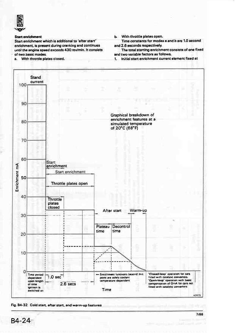
Surl snrichmmnt h With throttle plstes open. Smn enrichment which is additional to 'after start' ftme constants for modes a and b are 1.0 second enrichment is present during cranking and continues and 2.6 seconds respectively. until the engine speed exceeds 430 revimin. It consists The total starting enrichment consists of me fixed
- of two basic modes. and two variable factors as follows. a. Wnh throttle plates closed. 1. tnitiai start enrichment current element fixed at
Graphical breakdown of enrichment features at a simulated temperature of 20°C (68°F)
Fig. 84-32 Cold start. afmr start. and warm-up features

20 mA [which is added to the 'after start' enrichment1 for either 1.0 or 2.6 seconds. 2. 'After start' enrichment - variable and dependent upon coolant temperature 3. Warm-up enrichment - variable and dependent upon coolant temperature
Figures 04-31 and 84-32 show details of the enrichment factor&
'Aher statt' enrichment When the engine speed exceeds 430 revlmin the K- Motronic engine management system proceeds into its 'after start' enrichment moda This ensures smooth engine running during the initial fuel injector stabilization period. 'After start' enrichment can be further sub-divided Into two bas~c elements, the magnitude and duration of which are solely dependent upon engine coolant temperature a. Plateau time ta Decontrol time
Figures 84-31 and 84-32 show details of the enrichment factors.
Warm-up enriehrnem This gradual decay of enrichment factor commences upon completion of 'after start' enriehment. Engine coolant temperatures at which warm-up enrichment
finishes differ for cars with or without catalytic convertem
The engine coolant temperature at which can f i e d with catalytic conveners nrvert to 'closed loop' operation is 40°C (104°Fj.
Figures B4-31 ~ n d 84-32 show details of the enrichment factors.
Cold start injsaion operation The cold stsrt injector has three basic modes of operation which are as follows.
1. Conventioml cold start injector operation Digital control enables precise.:cold start injector operation for all ambient temperatures. Engine coolsnt temperature is the most accurate method of determining the additional increase in mixture strength required fmm single point injection during cold starting (i.e. the cold start injector). Hence cold start injector operation is controlled by the K-Motronic ECU via inputs from the engine coolant temperature sensor.
Rates of cold start injection are preset and dependent upon four engine coolant temperature sites. Values of coolant temperature experienced in service between the four sites are calculated by direct interpolation. Coolant temperatures beyond site four -26OC (-t4.B0f) which is shown as the last site. are
Mode l
Mode 2
. 1 . 3 , .. ..v 8
&_L ----,,,,
B
Durationof
-
.. b* cold start 3 L
injector I 1 roperation I
(seconds)
1 I ' 1 I I ..... .................. ....
W :: j.;".'$) ;c : .......... 1 ,::?.<c: . . . . . . . 3 I ..,.............. ( ......... ..:..
4 O ' C -30.C -.iv-c -10 'C V C 10'C 20'C 90 'C 100-C I lO'C (40.F) ( -2Z'F) (4 'F ) (1 4'F) (32'FJ (50.F) (68-F) [ l 94.F) (2 1 Z'F) (230.F)
I Engine coolant temperature
Fig. 34-33 Cotd stam injector operation
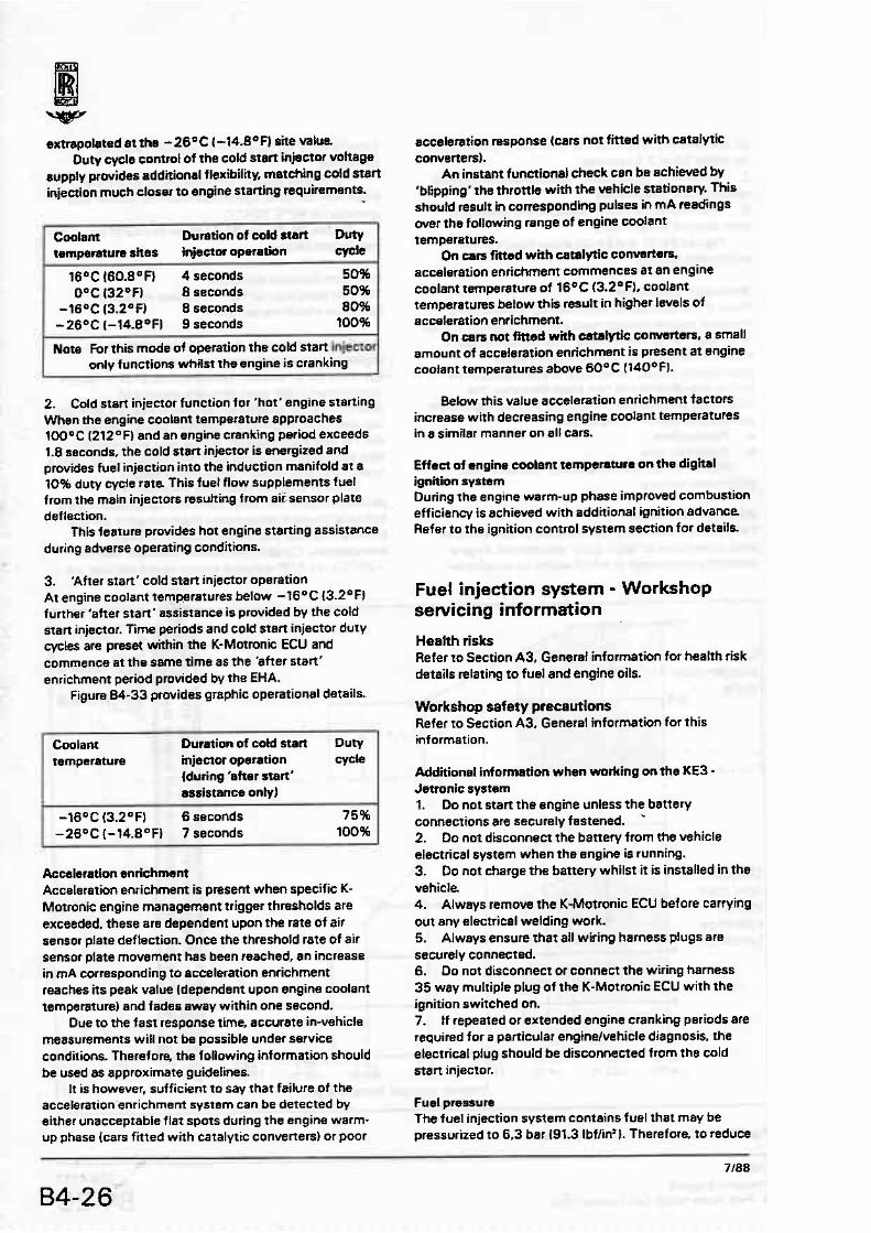
extrapoleted at the -26% l-14.R°F) site wlua Duty cycle controt of the cold start injector voltage
supply prwides additional flexibility, matching cold stert injection much closer t o engine starting requirements.
Coalam Duration of cold start Duty I tempemturn sites mjectnr operation M e
16OC (60.8°F} 4 seconds 50% O°C 132OF) 8 seconds 50%
-16OC (3.2Of) 8 seconds 80% -26OC l-14.BDF) 9 seconds 100% - Nate For this mode of operation the cold start Inperm
only functions whilst the engine is cranking
2. Cold start injector function for 'hot' engine starting When the engine coolant temperature approaches 100°C (212O F) and an engine cranking period exceeds 1.8 seconds. the cold start injector is energized and provides fuel injection into the induction msnifold at a 10% duty cycle rate. This fuel flow supplements fuel from the main injectors resutting from aii,senwr plate deflection.
This feature provides hot engine starting assistance during adverse operating conditions.
3. 'After start' cold start injector operation At engine coolant temperatures below -16*C (3.2OFI further 'after stan' assistance is provided by the cold start injector. Time periods and cold stsrt injector duty cycles are preset within the K-Motronic ECU and commence at the same time as the 'after start' enrichment period provided by the EHA.
Figure 64-33 provides graphic operational details..
Coolant Duration of cold start Duty temperature injeeror operation
{during 'after start' assistarm ontyl
-
-1S0C (3.2 FI 6 seconds 75% -28°C I-?4.B0F1 7 seconds 100%
---
Accskration enrichment Acceleration enrichment is present when specific K- Motronic engine management trigger thresholds are exceeded, these are dependent upon the rate of air sensor plate deflection. Once the threshold rate of air sensor plate movement has been reached. an increase in mA corresponding to acceleration enrichment reaches its peak value (dependent upon engine coolant temperature) and fades away within one second.
Due to the fast response time, accurate in-vehicle measurements will not be passible under service conditions. Therefore, the following information should be used as approximate guidelines.
It is however, sufficient to say that failure of the acceleration enrichment system can be detected by either unacceptable flat spats during the engine warm- up phase (cars fitted with catalytic converters) or poor
acceleration response (cars no! fitted with catalytic converters).
An instam functional check can be aehiwed by 'blipping' tha throttle with the vehicle stationary. This shwtd result in corresponding pulses in mA readings over the following range of engine coolant temperRtures.
On csrs fitted with catalytic converters, acceleration enrichment commences ar an engine coolant temperature of 16OC (3.2O F), coolant temperatures below this result in higher levels of acceleration enrichment.
On cars not Rttsd with catalytic converters, a small amount of acceleration enrichment is present at engine eaotant temperatures above 6 0 ° C (140°fl.
Below this value acceleration enrichment factors increase with decreasing engine coolant temperatures in a similar manner on all cars.
Effect of engine coolant temperature on the digital ignition system During the engine warm-up phase improved combustion efficiency is achieved with additional ignition advance. Refer to the ignition eontml system section for details
Fuel injection system - Workshop servicing information
Health risks Refer to Section A3, General information for health risk details relating to fuel and engine dls.
Workshop safety precautions Refer to Section A3, General information for this information.
Addaional information when wnrkmg on the KE3 - Jetmnic system 1. Do not start the engine unless the battery connections are securely fastened. *
2. Do not disconnect the battery from the vehicle electrical system when the engine is running. 3. Do not charge the battery whilst it is installed in the vehicle 4. Always remove the K-Motronic ECU before carrying out any electrical welding work. 5. Always ensure that all wiring harness plugs are securely connected. 6. Do not disconnect or connect the wiring harness 35 way multiple plug of the K-Motronic ECU with the ignition switched on. 7. If repeated or extended engine cranking periods are required for a particular enginelvehicle diagnosis, the electrical plug should be disconnected from the cold stan injector.
Fuel pressure The fuel injection system contains fuel that may be pressurized to 6.3 bar 191.3 Ibffin'l. Therefore. to reduce

I Symptom I 1 I Engine fails to start or starts with difficutty when cold I 1 1 h Engine fails to start or stafls with difficutty when hot I I I I I Uneven idle quality during the warm-up phase I I I I I 1 Poor throttle response I
Engine misfires during high speeUlosd operation
Unsatisfactory engine performance (is 'boost' restricted to 'base pressure characteristic' complete controt system functional check)
Fuel consumption tw high
Flat spot during acceleration
Idle CO concentration too high
Idle CO cancentration too low
Idle speed outside limits
Engine starts then immediately cuts out
Refer to workshop procedure
Possible wuse - - Fuel pump and/or prrpurnp not operattng correctly 1
2 piston seizure 3 sensor plate 4
Incorrect operation of idle speed actuator or poar throttle pbate seating 5
, c -
6 7 - Incorrect primary fuel pressure 8
R- Incorrect differential fuel pressure 9 - Leaks tn fuel system 10 d b - Faulty injectors I t -r- Unequal fuel delivery from distributor 12 - Throttle plates not opening correctly 13
Fuel accumulator diaphragm burst 14 - Blocked alr fitter or ducting 15 Incorrect 'starting enrichment' function
- Incorrect 'futl-load enrichment' function system - Incorrect inductton manifold pressure electrical test - lncorrea electrical connections at EHA programme
Faulty engrne coolant temperature sensor Faulty a ~ r pressure transducer f ~ g M-35)
Fig. 84-34 Basic KN-Jetronic fault diagnosis chaH

the risk of possible injury and fire, always ensure that the system is depressurized using the following mettrod, before commencing any work that will entail opening the system. 1. Clean the inlet connection to the fuel filter. 2. Wrap an absorbent cloth around the joint. ;
3. Carefully slacken the pipe nut to release any pressurized fuel from the system. 4. Tighten the pipe nut. 5. Discard the absorbent cloth in accordance with health and safety regulations
Exhaust gases When running turbocharged engines for prolonged periods within enclosed working.areas.. always ensure that the exhaust gases are removed safely.
Whilst direct exhaust gas ventilation is available in some workshop areas, it is inevitable that extraction hoses wilt have to be used in certain circumstances, particularly when the vehicle is 'ramp bound'. In these specific instances, the large flexible exhaust adapter shrouds must be fitted to prevent a high level of depression being applied to the exhaust turbine seal in the turbocharger.
Under no circurnstancrts should high depression exhaust gas extraction units be applied directly to the tailpipes.
Fault diagnosis This fault diagnosis section includes. Basic systam test procedures Electrical and electronic components fauh diagnosis Mechanical components fauh diagnosis 'On-board' fault diagnosis coding (cats fitted with catalytic convertersl.
It is important that fault finding is carried.out in.the. sequence given to prevent incorrect diagnosis which could result in both lengthy and costly repaira
Often, a mechanical fault has sufficiently welt defined symptoms to enable a very rapid diagnosis to be made
The basic fault finding procodurn is as follows, noting that any faults found in one system shoutd be rectified before moving onto the next stage of the procedure. 1. Check the integrity of all hose and electrical connections. Xghten where necessary. 2. Check the condition of the sparking plugs. 3. Carry out a compression test on the engine cylinders. inhibit the aperationof the fuel injection and ignition systems during this test by removing the respective fuses. 4. Stan the engine.
On cars fitted with catalytic converters, turn the ignirion key from the LOCK to the RUN position and observe that the 'Check Engine' warning panel is illuminated. Continue to turn the key to start the engine. As the engine starts check that the warning lamp extinguishes. If the lamp remains illuminated, refer to the bn-board'. diagnostic Iisting [see fig. M-361. 5. Ensure that the engine is running on all eight cylinders.
8. Allow the engine to fully warm-up, whilst noting the following. a. Cheek the fuel injection system for leaks. R Cheek that the vacuum system hoses and pressure - pipes are free from leaks. c Check that the crankcase emission control system hoses are free from leaks. d. Check the entire induction system for audible air leaks. paying particular attention to components downstream of the air flow sensor plate
This is particufarty important on cars fitted with catalytic converters, in view of the systems ability to learn and provide fimited air leek compensation. 7. Ensure that the idle CO is correct by checking the idte mixture strength. 8. Ensure that the idle speed actuator stabilizes the engine idle speed at 580 2 20 revlmin regardless of load. 9. Carry out basic engine management system checks to ensure that the fuel injection and ignition control systems are functioning correetfy.
During manufacture. components of the fuel injection system are precisely adjusted in order to -eompiy with the relevnnt emission control mgulations. Therefore, aherstians to any of the settings should not normally be necessary.
Before commencing any fault diagnosis or work on the fuel injection system, ensure that the workshop safety precautions are fully understood.
Fuel injection and ignition system functional checks The following series of functional cheeks are necessary to ensure the correct definition of the ignition and fuel systems 'maps'.
Always use a good quality digital multi-meter to carry out the tests. Note The checks must be carried out with the engine
stabilized at its normal operating temperalure.
Thrortle position switch - continuity cheek 1. With the engine switched off, disconnecr the four way electrical plug to the throttle positjon switch (see fig. 04-37}. 2. Always ensure that movement of the throrties is controlled by The accelerator pedal for these tests.
Idle 3. Using the multi-meter. carry out a continuity test across the blaeklpink and bluelpurple cables from the switch as follows. 4. With the throttles closed the multi-meter buzzer should sound. 5. With the throttles fully open the buzzer shoutd not sound. 6. f he switching point should be just off the idle position and confirmed by an audible click.
Full load 7. Using the multi-meter, carry out a continuity test across the blacklpink and yellowlpurpte cables from the switch as follows. 8. With the throttles closed the multi-meter buzzer

Fuel i.njection.sys;tem - electrical- test', program:ma fault diagnosis, .,.c hart
Sheet1 o f 2 . . .
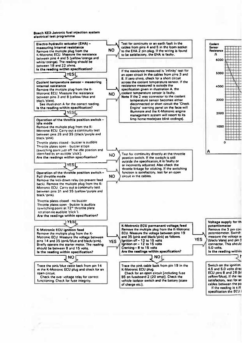
KE3-Jetronic fuel infection ryStOm electrical test progrmmmm
Test for confinuity or an earth fault in the
Remove rhe muhiple plug from the K-Motronrc ECU. Measure the resistnnce between pins 4 and 5 (yellmdorange snd whitworange). The reading should be between 18 and 22 ohms. tn the rending withln np~eifientien? If the resistance measured is 'infinity' test for I
an open circuit in the cables from pins 3 and 8. If zero ohms, check for a short circuit
Coolant ternperbure sensor - menwring across the coolant temperature sensor. If the internal redstancm resistance measured is outside the Remove the rnuttiple plug from the K- specification g ~ e n in illustration A, the Motronic ECU. Measure the resistance coolant temperature sensor is faulty. between pins 3 and 8 (yeHow/blue and Mats If the 2 way connector to the coolant blsck,'slate). temperature sensor becomes either
See illustrarron A for the correct reading. disconnected or shon circuit the 'Cheek Is ths reading within spscification? Engine' warning panel on the facia wilt
illuminate and the K-Motronic engine .- management system will nson to its Operstion of the throttle position switch - limp home modetsee blink codings). Idle mode Remove the muhiple plug from the K- Motronic ECU. Carry out a continuity test between pins 2G and 35 (blacWpurple and black'pink]. Throttle plates closed - buzzer is audible Thronle plates open - buzzer stops (sw~tching polnt )us1 off ?he idle posltion and h identrf~ed by an aujible'cl~ck'). T951 for continuity directly at the throttle Are the readings within spectfication? position switch. I f the switch is still
outside the specification, it is faulty or or ineotrectly adjusted. Also check the throttle linkage for sticking. If the switching function is satisfactory. test for an open circuit in the cables.
Remove the krck-down relay (to prevent feed h
back). Remove the multiple plug from the K- Morronic ECU. Carry out acontinuirytest between plns 31 and 35 (yellow/purple and black'pink).
Throttle plates closed . no buzzer Thronle plates open - buzzer is audible (switching paint a t 72" throttle plate rotation no audible 'click'l.
Ara the remdingu within speeificotion?
v
t K-Matronic ECU permanrnt v o l ~ g ~ f ~ e d K-Motronie ECU ignition hod Remwa the multiple plug from the K-Mbtronic Remove the multiple plug from the K- ECU. Measum the voltage between pins 19 Motrofiic ECU Measure the voltage be~wren and 35 (pink a d blacldpinw as followk 2 pins 14 snd 35 (plnWblue and blacUpink). Ignition OH - 12 to 15 w l t ~ YES
Voltage supply fo r th patmtiometer Remove the 3 pin con1 wtentiome~er, Switch measure the voltage u
. S (blacldslate] and pin 3 Briefly operate the staner motor. The readlng Ignition m - 12 10 15 volts ,/ connector. This s b u l d should be between 8 and 15 wrlis. Cranking - 0 to 1 5 vdU 5.0 volts. 11 the reading within spseification? Arm the rodings within spscificmtion? Is the reading witkiin
NO I
l of charge etc.). cables between the PO
If the reading is s i l l
Y T rsee the pinldblue cable back from pin 14 in the K-Molronic ECU plug and check for an ape n circuit.
Y
Trace the pink cable back from pin 19 in the Switch on the ignition K-Motronic ECU plug. 4.5 and 5.0 volts dkec
Check for an open circuit [including fuse ECU pins B and 26 [bl Check the over voltage relay for correct 85 on fuseboard 2 120 amp)]. Chack the yellow/blue). If the rea
functioning. Check for fuse integrity. vehicle isolator switch and the batlary {state satisfactory, test for an
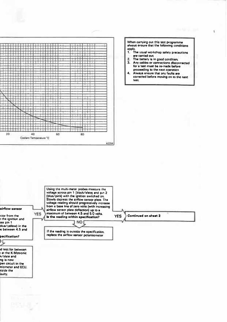
ridlow sensor I ?
etor from the W5 ? the ignition and ~s pin 1 blue/yellow) in the le between 4.5 and
peeification? I
Id lest for between r at the K-Morronie Vslate and ng is now pen circuit in the miometer and ECU. rtside the lauhy. p-
Using the multkmeter probes measure !he voltage across pin I (blacWslate) and pan 2 {bludpink) with the ignition switched o n Slowly depress fhe airflow sensor plate. The voltage reading should progressively increase from a base Line of zero volts [with increasinu . .
airllow sensor plate defyectioi up to s bmaximum of between 4.5 and 5.0 volts. Is the reading within spscification? 3 Continued on sh9.t 2 1
\
If the reading is outside the specification. replace Ihe airflow sensor potentiometer I
I
I
r i n g out this lest propramme -
always ensure that the following conditions apply. l . The usual workshop saiety precautions
err carried out. 2. The banery is in gaod condition 3. Any cabks or connections disconnected
for a test must be re-made before proceeding ta the next opration
4. Always ensure that any faults ere corrected before rnwing on to the nexf test.
!
Fuel injection system - electrical test programme - fault-diagnosis chart
Sheet 2-of 2
2 89 TSD 4737

Contlnumd from sheet l I I
Full Imd enrrchmen: I without c o r r t c t ~ ~ ~ ~
I I
i i -----__ 12,--- 7 . . .
B 9 - d 5ucptV
ro €HA 6
4 . I
2 2 i
I I
r936 7 m l5w IOW 3500 &an Engwnc spced (rev/man)
B &=Yam
Stnnd cunrn t Connect a digital multi-meter in series with the €HA using the special adapter RH 9893. :v ~ I I switch on the ignition. Note that the stand 1 #
current should remain constant at l00 t 2mA whilst the ignition is switched on. This ",X' "[ should also resuh in m audible buzz as both rQ the pre and main fuel pumps energize for
' 9'
r ;l= aac rl#R
approximately 1 second. Is the reading within specification?
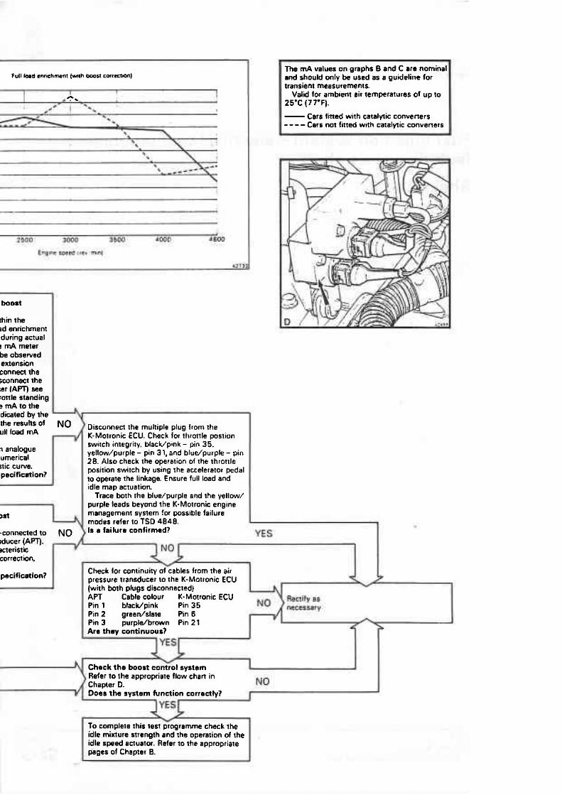
Starting, nhat start. and warm-up snrichment If the reading is outside the specification (and Connect a digital multkmeter in seties with the EHA using the special adapter RH 9893. Stan the engine whilst observing the multi- meter read~ng. Consuk the enrichment factors (fig. 84-31 1. Cross check the NQ
all preceding tests in the programme have been successfully carried out), the K-Motronic ECU is faulty.
I f no reading is obtained, check for an open or short circuit in the leads from pins 4 and 5
1
F
start. after sran, and warmup factors with (yellow/orsnge and whitdorange] on the the vehicle's coolant qemperature. K-Motronic ECU to the €HA Note Refer to note regarding coolant Rectify reeds and/or replace the
temperalures ar the botlorn of figure K-Motronie ECU 84-3 1 .
Are readinas within specification?
Full i o d enrichment (wi:houl coneetion) Due to plausibility constraints W.
K-Motronic ECU. if loss d lull Ic. is suspected it must be checked vehicle operation. Fit an analmu
g conditions - hoa IUIM
vA 1 With he engine running at idle speed (5BD * 20 tev/minl and an engine coolant
such that the meter reading can by a front seat passenger. Usirq leads and the adapter RH 989 3 meter in series with the EHA. D, K-Motronic air pressure transdu illustration D. Complete a full tb sun acceleration and mmitor $t
temperature of at least 8WC 11 76'F). check E H 4 along with engine speed ii the supply of rniHiamps to the EHA. while tachometer. Cross check Cars not f i t tsd with ca l~ ly t ic conv*rtars YES
the tes againn the appropiate Supply is f i ~ e d at a nominal value of OmA t t mA. Cars fitted with catalytic converters Supply should oscillate about a median of OmA with s band width of 2 3mA. Is the roading within specificetion?
I map, see illustration B. Due to the slow response of i
meter only consider the salient : points on the full load character Is the range of valuas within
-.
Full l a d enrichment (with bc can6etian) Ensure tha the pipe has h n n the K-Motronic air pressura Iran
Repeat the prwious test Cha~ cuwe should now include bwsl see illustration C Is the range of values within
Full bad enrichment (mlh b-61 ccnrcomn)
I i 1 *A*- -
5 X 1
9 'C
- -
+ a*d 7Mk ! 5CC rMCl 16W
tnw- r a m ? I?. m 4
U 1
thin the ad enrichment during actual ! mA meter be obsewed extension connect the ; w n m the *r (APT) see .artle standing ? rnA to the dicated by the
ult the load results mA of v L NQ
a analogue urnerica1 :tic cuwe. pecification?
connected to NO iducer (APT). #cleristic correction. r pecif ication? I
Disconnect the multiple plug from the K-Morronic ECU. Check for throttle postion switch integrity, bIacWpmk - pin 35. yetlow/purple - pin 3 1, and bludpurple - pin 28. Also check the operation of the throttle position switch by using !he accelerator pedal to operete the linkage Ensure full load and idle map actuation
Trace both the blue/purple and ihe yellow/ purple leads beyond the K-Motronic engine management system !or possible failure modes refw to TSD 4848.
:, Is a failure confirmed?
l'he mA valuer on graphs B and C are nominal and should onty be used as a guideline for transient measurements.
Valid for ambient air temperatures of up to
Check ior continuity of cables from the air 7
pressure transducer to the K-Motronic ECU (with both plugs disconnected) APT Cable colour K-Motronie ECU Ptn 1 blacldpink Pin 35 Pin 2 greedslate Pin 6 Pin 3 purpldbrown Pin 21 1 Are they continuous?
Check the boost controt system - Refer to the appropriate flow chan in Chapter D. NO Does the rystarn function correctw r
1 To complete this test programme check the idle mixture nrenarh and he ooeration d the I idle speed actuator. Refer to the appropriate pagts of Chapter B.

The Rolls-Royce Owners' Club of Australia Technical Library www.rrtechnical.info
The Rolls-Royce Owners' Club of Australia Technical Library www.rrtechnical.info
The Rolls-Royce Owners’ Club of Australia Technical Library www.rrtechnical.info
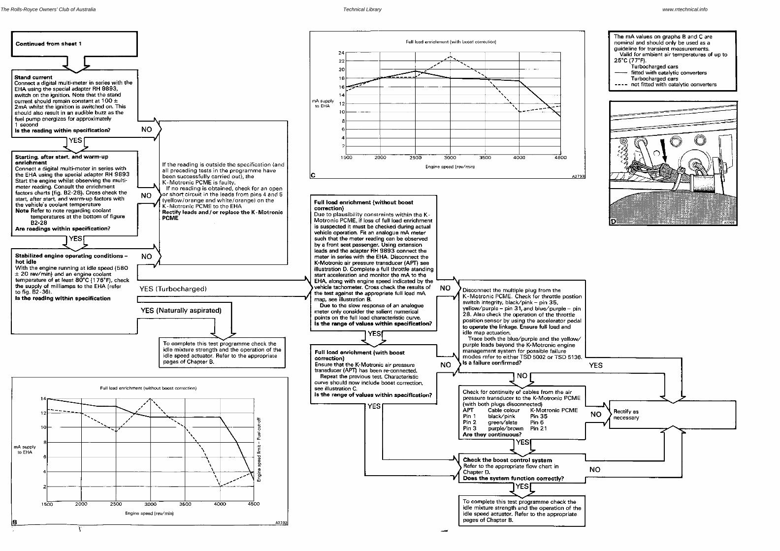
Fuel Distributor - Removed
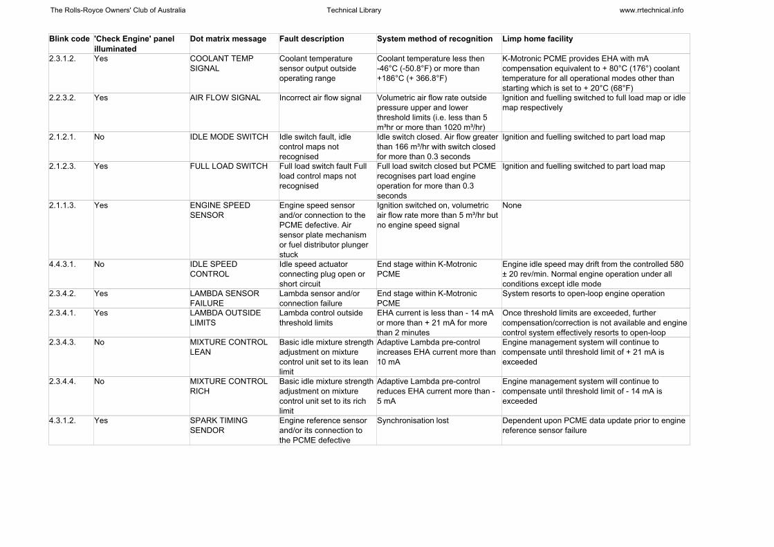
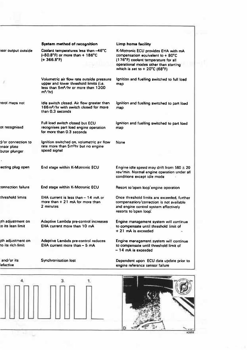
Blink code 'Check Engine' panelilluminated
Dot matrix message Fault description System method of recognition Limp home facility
2.3.1.2. Yes COOLANT TEMPSIGNAL
Coolant temperaturesensor output outsideoperating range
Coolant temperature less then-46°C (-50.8°F) or more than+186°C (+ 366.8°F)
K-Motronic PCME provides EHA with mAcompensation equivalent to + 80°C (176°) coolanttemperature for all operational modes other thanstarting which is set to + 20°C (68°F)
2.2.3.2. Yes AIR FLOW SIGNAL Incorrect air flow signal Volumetric air flow rate outsidepressure upper and lowerthreshold limits (i.e. less than 5m³hr or more than 1020 m³/hr)
Ignition and fuelling switched to full load map or idlemap respectively
2.1.2.1. No IDLE MODE SWITCH Idle switch fault, idlecontrol maps notrecognised
Idle switch closed. Air flow greaterthan 166 m³/hr with switch closedfor more than 0.3 seconds
Ignition and fuelling switched to part load map
2.1.2.3. Yes FULL LOAD SWITCH Full load switch fault Fullload control maps notrecognised
Full load switch closed but PCMErecognises part load engineoperation for more than 0.3seconds
Ignition and fuelling switched to part load map
2.1.1.3. Yes ENGINE SPEEDSENSOR
Engine speed sensorand/or connection to thePCME defective. Airsensor plate mechanismor fuel distributor plungerstuck
Ignition switched on, volumetricair flow rate more than 5 m³/hr butno engine speed signal
None
4.4.3.1. No IDLE SPEEDCONTROL
Idle speed actuatorconnecting plug open orshort circuit
End stage within K-MotronicPCME
Engine idle speed may drift from the controlled 580± 20 rev/min. Normal engine operation under allconditions except idle mode
2.3.4.2. Yes LAMBDA SENSORFAILURE
Lambda sensor and/orconnection failure
End stage within K-MotronicPCME
System resorts to open-loop engine operation
2.3.4.1. Yes LAMBDA OUTSIDELIMITS
Lambda control outsidethreshold limits
EHA current is less than - 14 mAor more than + 21 mA for morethan 2 minutes
Once threshold limits are exceeded, furthercompensation/correction is not available and enginecontrol system effectively resorts to open-loop
2.3.4.3. No MIXTURE CONTROLLEAN
Basic idle mixture strengthadjustment on mixturecontrol unit set to its leanlimit
Adaptive Lambda pre-controlincreases EHA current more than10 mA
Engine management system will continue tocompensate until threshold limit of + 21 mA isexceeded
2.3.4.4. No MIXTURE CONTROLRICH
Basic idle mixture strengthadjustment on mixturecontrol unit set to its richlimit
Adaptive Lambda pre-controlreduces EHA current more than -5 mA
Engine management system will continue tocompensate until threshold limit of - 14 mA isexceeded
4.3.1.2. Yes SPARK TIMINGSENDOR
Engine reference sensorand/or its connection tothe PCME defective
Synchronisation lost Dependent upon PCME data update prior to enginereference sensor failure
The Rolls-Royce Owners' Club of Australia Technical Library www.rrtechnical.info

![6. Wiring Diagram - · PDF fileFB-11 Radio FB-12 Cigarette lighter FB-13 Remote control rearview mirror switch FB-14 ... WIRING DIAGRAM 6. Wiring Diagram. MEMO: 21 WIRING DIAGRAM [D6A2]](https://static.documents.pub/doc/80x56/5ab1b6427f8b9a00728cab2a/6-wiring-diagram-radio-fb-12-cigarette-lighter-fb-13-remote-control-rearview.jpg)


