Powder Technology, 61 (1990) 143 - 154 Theories on Channeling: Reviewed and Compared with Experiments M. P. JONGEJAN* Laboratory for Bulk Solids Storage, Handling and Transportation, University of Twente {The Netherlands) (Received April 21, 1989; in revised form December 1989) 143 SUMMARY Discharge of a cohesive bulk solid from a plug-flow bin is (too) often interrupted by the development of a stable channel within the bulk solid. In this article, various methods to determine critical outlet dimensions to avoid channeling are reviewed critically and com- pared with the results of experiments. It is shown that the results of these methods vary between an underestimation and an extreme overestimation of the critical outlet dimen- sions. Experiments have been performed using different bins and bulk solids. In contrast to what is generally assumed, these experiments showed that critical outlet dimensions for arching can be larger than those for channel- ing. It also appeared that fitting a smooth hopper underneath a bin results in a smaller critical outlet than a flat bottom. INTRODUCTION One of the problems which may occur during discharge of a bulk solid from a plug- flow bin is the development of an empty channel within the bulk solid. This empty channel extends from the outlet to the upper surface of the material. The material sur- rounding the channel remains at rest (see Fig. 1). This phenomenon is often referred to as channeling or piping. According to Jenike [ 11, channeling can be avoided by enlarging the diameter of the out- let above a certain critical value. This critical diameter is related to both bulk solid prop- erties and bin geometry. Various methods can be found in the literature to determine this critical outlet diameter. Jenike and Yen [2] *Current address: AKZO Engineering, Arnhem (The Netherlands). 0032-5910/90/$3.50 follow a slip line approach, assuming that the consolidation of the bulk solid is determined by a steady flow situation. Johanson [3] follows the same approach, but assumes that the consolidation is determined by the initial stress field, which exists before the outlet is opened. Drescher [4 - 71 follows an approach based on limit analysis. A path of failure is assumed and the energy dissipation is equated to the work done by gravity. As every method yields a different critical diameter, it was felt that a review of these methods would be useful. The predicted critical diameters were compared with one another and with the results of experiments. Results of experiments concerning channeling relevant to our purpose could not be traced in the literature. So a series of experiments was performed. Two bins and two materials were used. The effects of a hopper and of time consolidation on the critical diameter were investigated too. PROBLEM STATEMENT The theories and experiments described in this article are confined to axisymmetric bins only. Theories are all based on collapse of an empty channel. The Mohr-Coulomb yield criterion, with the possibility of a tension cut-off, will be adopted (Fig. 2). Compression is assumed to be positive. The actual yield locus depends on the consolidation stress ul. Therefore, cohe- sion c, tensile strength ut, unconfined yield strength u,., effective angle of internal friction pe and static angle of internal friction qt all depend on ul. The tension cut-off is charac- terized by Q, an expression of ut, u, and cpt (Appendix A). Material properties of the interface between the material and a wall are described by the subscript w. @ Elsevier Sequoia/Printed in The Netherlands brought to you by CORE View metadata, citation and similar papers at core.ac.uk provided by Universiteit Twente Repository
Transcript
Powder Technology, 61 (1990) 143 - 154
Theories on Channeling: Reviewed and Compared with Experiments
M. P. JONGEJAN*
Laboratory for Bulk Solids Storage, Handling and Transportation, University of Twente {The Netherlands)
(Received April 21, 1989; in revised form December 1989)
143
SUMMARY
Discharge of a cohesive bulk solid from a plug-flow bin is (too) often interrupted by the development of a stable channel within the bulk solid. In this article, various methods to determine critical outlet dimensions to avoid channeling are reviewed critically and com- pared with the results of experiments. It is shown that the results of these methods vary between an underestimation and an extreme overestimation of the critical outlet dimen- sions.
Experiments have been performed using different bins and bulk solids. In contrast to what is generally assumed, these experiments showed that critical outlet dimensions for arching can be larger than those for channel- ing. It also appeared that fitting a smooth hopper underneath a bin results in a smaller critical outlet than a flat bottom.
INTRODUCTION
One of the problems which may occur during discharge of a bulk solid from a plug- flow bin is the development of an empty channel within the bulk solid. This empty channel extends from the outlet to the upper surface of the material. The material sur- rounding the channel remains at rest (see Fig. 1). This phenomenon is often referred to as channeling or piping.
According to Jenike [ 11, channeling can be avoided by enlarging the diameter of the out- let above a certain critical value. This critical diameter is related to both bulk solid prop- erties and bin geometry. Various methods can be found in the literature to determine this critical outlet diameter. Jenike and Yen [2]
*Current address: AKZO Engineering, Arnhem (The Netherlands).
0032-5910/90/$3.50
follow a slip line approach, assuming that the consolidation of the bulk solid is determined by a steady flow situation. Johanson [3] follows the same approach, but assumes that the consolidation is determined by the initial stress field, which exists before the outlet is opened. Drescher [4 - 71 follows an approach based on limit analysis. A path of failure is assumed and the energy dissipation is equated to the work done by gravity.
As every method yields a different critical diameter, it was felt that a review of these methods would be useful. The predicted critical diameters were compared with one another and with the results of experiments. Results of experiments concerning channeling relevant to our purpose could not be traced in the literature. So a series of experiments was performed. Two bins and two materials were used. The effects of a hopper and of time consolidation on the critical diameter were investigated too.
PROBLEM STATEMENT
The theories and experiments described in this article are confined to axisymmetric bins only. Theories are all based on collapse of an empty channel.
The Mohr-Coulomb yield criterion, with the possibility of a tension cut-off, will be adopted (Fig. 2). Compression is assumed to be positive. The actual yield locus depends on the consolidation stress ul. Therefore, cohe- sion c, tensile strength ut, unconfined yield strength u,., effective angle of internal friction pe and static angle of internal friction qt all depend on ul. The tension cut-off is charac- terized by Q, an expression of ut, u, and cpt (Appendix A). Material properties of the interface between the material and a wall are described by the subscript w.
@ Elsevier Sequoia/Printed in The Netherlands
brought to you by COREView metadata, citation and similar papers at core.ac.uk
Jenike’s method [ 21 is a so-called slip-line method. It is assumed that the vertical chan- nel already exists and that the material sur- rounding the channel is in a state of incipient failure. During incipient failure, stresses are governed by the yield pyramid describing the failure conditions of the bulk solid in the three-dimensional stress space. The stresses must also satisfy the equations of equilibrium. Thus it is possible to derive a set of differen- tial equations describing the slip lines devel- oping in the bulk solid at the moment of collapse.
Jenike uses the Mohr-Coulomb yield criterion, resulting in Shield’s yield pyramid. Assuming axial symmetry, Jenike assumes that the Haar-von Karman hypothesis for a passive stress field is valid. This hypothesis locates the stress state on a certain edge of the yield pyramid. At this edge, the tangential stress component is equal to the major principal stress. Using this relation, equations for the radial and axial stress components can be derived.
Substituting the stress components into the equations of equilibrium yields two hyper- bolic differential equations. At the moment of collapse, the characteristics of these equa- tions coincide with the slip lines. It is not possible to derive a critical diameter for chan- neling from these equations. Therefore, Jenike assumed that the stress field is inde- pendent of the vertical co-ordinate. This means that Jenike’s method is valid when the stress field throughout the height of the bin is constant. This is often assumed approxi- mately true in a situation of steady flow. In a non-flow situation, this is approximately true below a certain level in tall and slender bins only.
With this assumption, it is possible to describe the direction of the slip lines as a function of a dimensionless radial co-ordinate. Now there are two possibilities: either the slip lines extend throughout the bin without a limit, or the slip lines only extend throughout a limited part of the material (Fig. 3). In the first case, the plastic stress field is unbounded. In the second case, the plastic stress field is bounded, and the rest of the material is in an elastic state of stress. If the diameter of the channel is so small that an unbounded stress field is required for collapse, the channel is assumed to be stable. But if a bounded stress field can provide collapse, a channel is assumed to be unstable. The critical diameter for
Fig. 3. Bounded and unbounded stress fields.
145
channeling is the smallest diameter for which a bounded stress field still can provide collapse.
Thus Jenike derived the following relation for predicting the critical diameter for chan- neling:
(1)
G(v~) is a function derived by Jenike [8] and is described in [ 81.
The bulk solid properties used in eqn. (1) depend on the consolidating pressures exerted on the bulk solid. To determine this consoli- dation, Jenike assumes the material to be in a state of steady flow. Consolidating pressures are assumed to be exerted during flow by the moving mass inside the channel (Fig. 4(a)). This results in
Dcrit 1 + sin (Pe 01= 47
sin (Pe (2)
As Dcrit is not known yet, it is convenient to use a flow factor ff:
ff= : c
1 + sin (Pi =
4 sin (Pi WV,) (3)
The intersection of this flow factor with the flow function yields the consolidating pres-
Fig. 4. Consolidation: (a), by steady flow pressures; (b), by initial pressures.
sure ui. Now, uc and y and thus Dcrit are known. It will be clear that Jenike’s method is fully independent of the bin geometry.
JOHANSON’S METHOD
Jenike assumes steady flow conditions to determine the consolidation. This results in a low material consolidation. Consolidation by the stress field existing before opening of the outlet is neglected. It is assumed that this consolidation is destroyed the moment flow starts. Johanson, however, points out that the material outside the channel does not flow at all. So he states that consolidation by the ini- tial stress field will not be destroyed outside the channel. Hence, the consolidation that should be taken into account in the analysis of channeling is the consolidation by the ini- tial stress field (Fig. 4(b)).
Before the outlet is opened, the stress field resembles the Haar-von Karman active state of stress. This means that the major stress component is approximately equal to the vertical stress component. Thus consolidation can be described by Johanson [3] as
Pi@ = 4 X tan cpW
(1 _ e-4 h tan v&D) (4)
where X is the ratio of horizontal to vertical stresses and cpW is the angle of friction between wall and bulk solid.
Now ui depends on the position in the bin. In a flat-bottom bin, u1 will attain its maxi- mum at the bottom of the bin. To be sure that nowhere in the bin a stable channel can develop, this maximum of u1 has to be reckoned with. If an average of u1 were used, it would be possible for the bigger part of the bin to empty nicely. But near the bottom, where consolidation is maximal, a stable chan- nel could remain. Using this maximum intro- duces an upper bound to the actual critical diameter.
To determine the critical diameter, Johanson follows Jenike’s method. But instead of using the flow factor, Johanson uses initial pressures to calculate the consoli- dating stress ui. The material properties can now be substituted into eqn. (1) and the critical diameter can be determined.
146
Flow of a bulk solid from a bin is often regarded as a continuous development and collapse of arches. After opening the outlet of a plug-flow bin, arches might develop inside the channel. This is confirmed by the very erratic type of flow. Development and col- lapse of arches introduces pressure peaks, which might well influence the material sur- rounding the channel. In this way, initial consolidation might be (partially) destroyed.
The outer diameter of the plastic stress field that is used by Jenike to determine the critical diameter can also be calculated. This outer diameter is a function of the critical diameter and the static angle of internal friction. Johanson does not take bin walls into account. Furthermore, Johanson uses a height independent stress field, so Johanson’s method should (only) be used for slender bins. These two conditions considerably restrict the applicability of Johanson’s method.
DRESCHER’S METHOD
This method is based on the so-called upper bound theorem of the method of limit analy- sis [9 - 111. The method of limit analysis is based on the concept of a perfectly plastic material, obeying a flow rule associated with the yield condition. For such a material, an upper bound to the true collapse load can be determined.
The upper bound theorem is based on an energy equation. For a given, kinematically admissible way of collapse, the rate of inter- nal dissipation is equated to the rate of work done by gravity. In the case of channeling, both internal dissipation and work done by gravity are related to the channel diameter. Thus, by solving the energy equation, a critical diameter can be found. The upper bound theorem states that the critical diam- eter thus found is an upper bound to the actual critical diameter. Or, if a path of failure exists, a channel cannot be stable.
Drescher suggested several paths of failure for the material surrounding the empty chan- nel [4 - 71. All but one are based on collapse of a rigid block out of the channel wall, the so-called partial collapse. It is assumed that partial collapse causes the whole channel to collapse. By using a rigid block, the energy
equation is much simplified. Dissipation takes place in an infinitely thin layer between the block and the material that remains at rest. The rate of work done by gravity equals the total weight of the block multiplied by the vertical velocity component,
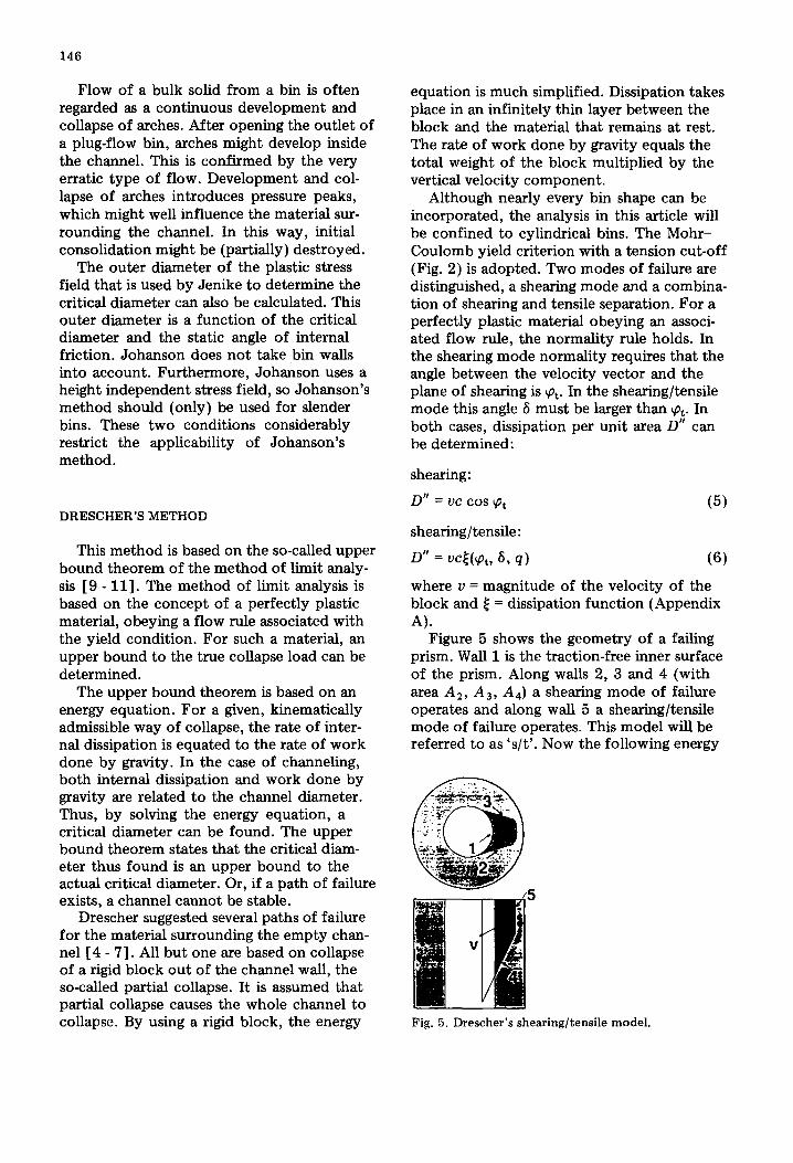
Although nearly every bin shape can be incorporated, the analysis in this article will be confined to cylindrical bins. The Mohr- Coulomb yield criterion with a tension cut-off (Fig. 2) is adopted. Two modes of failure are distinguished, a shearing mode and a combina- tion of shearing and tensile separation. For a perfectly plastic material obeying an associ- ated flow rule, the normality rule holds. In the shearing mode normality requires that the angle between the velocity vector and the plane of shearing is qt. In the shearing/tensile mode this angle 6 must be larger than pt. In both cases, dissipation per unit area D” can be determined:
shearing:
D” = UC cos yL+
shearing/tensile:
D” = &(P,, 679)
(5)
(3)
where u = magnitude of the velocity of the block and l = dissipation function (Appendix A).
Figure 5 shows the geometry of a failing prism. Wall 1 is the traction-free inner surface of the prism. Along walls 2, 3 and 4 (with area A,, A3, A4) a shearing mode of failure operates and along wall 5 a shearing/tensile mode of failure operates. This model will be referred to as ‘s/t’. Now the following energy
Fig. 5. Drescher’s shearing/tensile model.
147
equation has to be solved to find a critical diameter.
I c cos Pt c&,3.4 + s a% 69 Q) u,
A 2. 3.4 A5
= s
Y cos(P + cpd dVb (7) “b
If wall 5 coincides with the bin wall, then properties describing the behavior of the interface between bulk solid and wall should be accounted for. Dissipation along wall 5 is
s GJt(%, ~94w) a5 (8) -45
Drescher solved this equation, assuming that c, y and cpt are constant throughout the bin. Solving this equation for one particular prism gives one critical diameter. The dimensions of the prism can be varied, provided that bin dimensions are not exceeded and the mode of failure is admissible. With every new prism, a critical diameter can be determined. These diameters are all upper bounds to the actual critical diameter. The smallest critical diam- eter thus found is the best approximation to the actual critical diameter.
As c and 7 vary with consolidation u 1, the same difficulty as with Jenike’s method arises. To be sure of an upper bound, consolidation should be determined according to Johanson. This method was used for the s/t model. In a bin with H/D < 1, c1 is nearly linear with the vertical co-ordinate z. Using Jenike’s shear tester, c( ui) and ?(a,) can be determined. Introducing c(z) and y(z) makes it possible to take varying material properties into account. This model will be referred to as ‘s/t-var’ and is described in Appendix A.
Another model by Drescher concerns a prism which fits into a conical hopper. Using this prism, failure along the hopper wall can be simulated. Again c and 7 are assumed con- stant and the prism is suited for a hopper only. In this work, the prism has been extended for use in a cylindrical bin with a hopper fitted underneath. Material properties inside the hopper are assumed constant, while in the cylindrical part they are assumed variable. This model will be referred to as ‘cyl/hop’.
Drescher’s models can easily be adapted to different kinds of bins, hoppers and bulk solids. The yield criterion used by Drescher is a better approximation to the actual yield locus than the condition used by Jenike. A serious disadvantage of Drescher’s method is the amount of calculations that has to be per- formed in order to find the smallest possible critical diameter. Furthermore, the required dilatation angle qt is an overestimation of the true dilatation angle [ 12 - 131. A larger dilata- tion angle leads to a larger critical diameter. So, by assuming a dilatation angle cpt, another (higher) upper bound is introduced.
EXPERIMENTS
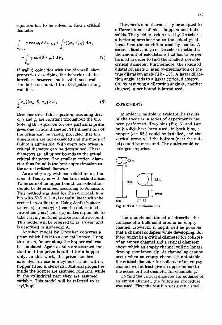
In order to be able to evaluate the results of the theories, a series of experiments has been performed. Two bins (Fig. 6) and two bulk solids have been used. In both bins, a hopper (a = 55”) could be installed, and the vertical pressure at the bottom (near the out- let) could be measured. The outlet could be enlarged stepwise.
CD 0.8 m
15m m
0.9 m
bin I bin II
Fig. 6. Test bin dimensions.
The models mentioned all describe the collapse of a bulk solid around an empty channel. However, it might well be possible that a channel collapses while developing. So, there might be a critical diameter for collapse of an empty channel and a critical diameter above which an empty channel will no longer develop spontaneously. As channeling cannot occur when an empty channel is not stable, the critical diameter for collapse of an empty channel will at least give an upper bound to the actual critical diameter for channeling.
To find the critical diameter for collapse of an empty channel, the following procedure was used. First the test bin was given a small
148
outlet, above which an arch developed. Then the outlet was enlarged gradually until the arch collapsed. When an empty channel was left, this channel was enlarged stepwise until it collapsed. The diameter at which collapse occurred is the critical diameter for collapse of an empty channel.
Often the test bin emptied nearly com- pletely after collapse of the arch above the outlet. Apparently, the critical diameter for arching exceeded the critical diameter above which an empty channel would no longer develop! When an empty channel would not develop spontaneously, it was created manually to find the critical diameter for collapse of an empty channel.
The first material used was bentonite; its bulk solid properties are described in Appen- dix B. Stable channels did not develop spon- taneously. In the tall bin (No. I, Fig. 6), it was not possible to create a stable channel extending throughout the whole height of the bin. When the channel was emptying, flow was very erratic and the bin started shaking violently. Collapse always started along the wall of the bin. In the small bin (No. II, Fig. 6), a stable channel could be created manually. Before collapse, the upper surface of the powder was littered with deep tensile cracks. Collapse occurred nearly simulta- neously in the whole area surrounding the channel.
The other material used was a detergent (Appendix B). In the small bin, a stable channel developed after collapse of the arch. But with an outlet above a certain critical diameter, the channel collapsed while devel- oping. This diameter is the critical diameter for spontaneous development of an empty channel. Using an outlet diameter smaller than this critical diameter, an empty channel was created. When this empty channel was widened, collapse occurred when the diam- eter of the channel reached a certain critical diameter. This diameter is the critical diam- eter for collapse of an empty channel.
During collapse of a developing channel, the following could be seen. First the arch above the outlet collapsed. A part of a chan- nel with an arch above it was left. Then the arch did not move upward, but the walls of the channel collapsed, thus widening the channel. This went on until a certain diam- eter was reached, then the arch started
moving upward. This diameter was larger than the critical diameter for collapse of an empty channel. Afterwards, a channel was left in the lower part of the bin. This process occurred in both bins and is illustrated by Fig. 7. Collapse of an empty channel started with the collapse of a block of material out of the channel wall. When a hopper was installed, this occurred at the hopper wall. Otherwise, the location of collapse was random.
Fig. 7. Collapse of the walls of a channel.
The results of the experiments (critical diameters) are presented in Table 1. The crit- ical diameter for arching is referred to by ‘arch’, the critical diameter for collapse of an empty channel by ‘channel art.’ and the crit- ical diameter for collapse of a developing channel by ‘channel spont.’
RESULTS AND DISCUSSION
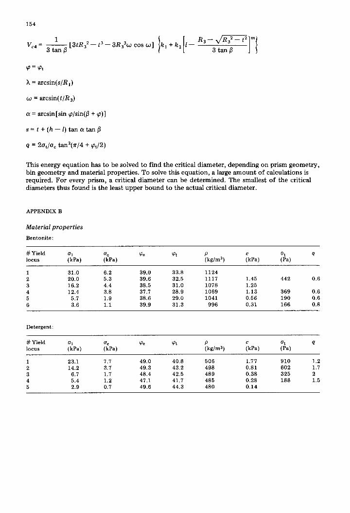
By means of a Jenike shear tester y(o,), c(ui) and cpt(ai) were determined. Unconfined yield strength u‘,(ui) is determined by c(ui) and ~~(a,). A tensile tester [14] was used to determine q. A modified shear tester was employed to determine the material proper- ties at the interface between bulk solid and bin wall.
Two series of fictitious materials were created in order to compare the results of the various methods. The first series, based on bentonite, is defined thus. All properties of the fictitious material are identical to those of bentonite, except for cohesion (and thus (2,).
149
TABLE 1
Results of the experiments
Material Bin # Ex~.~ Arch (cm)
Channel (cm) Comments
spont. art.
Bentonite
Base detergent
6
3 3 5 2 1
3 1 2 2 1
3 1 4 3 2
16
16
26
26 26
< 16 -
< 16 13 flat bottom 14 17 18
< 26 18 h. tcb/flat bottom 38 18 h. tc/flat bottom 40 18 h. tc/flat bottom 34 18 h. tc/hopper 550c 36 18 h. tc/hopper 55”
“# Exp. : number of experiments yielding this result. b tc: time consolidation by undisturbed storage. =55”: angle between hopper wall and vertical.
Cohesion of the fictitious material is defined as c = f. cb&ci). Here, cbent(oi) is the cohe- sion of bentonite, depending on the consoli- dating stress oi. Each fictitious material of this bentonite-based series is characterized by the dimensionless factor f. In a similar way, the second series of fictitious materials is based on detergent. All material properties are identical to those of detergent, except for cohesion, which is defined as c = f*cdet.(ul).
As u, is related to c (Fig. 2), the critical diameters according to the various methods can now be calculated. These critical diam- eters depend on bin geometry, and are func- tions of f for both series of fictitious materials (Figs. 8 - 10, Table 2). Each line represents the critical diameter in relation to f as pre- dicted by a given method. Bentonite and detergent are represented by f = 1. The area to the left of a line represents unstable situa- tions. The average of the experimentally determined critical diameters for collapse of an empty channel is presented by ‘0’. The critical diameter for collapse of a developing channel by ‘o-sp’.
Johanson and Drescher use initial pressures to determine consolidation. These initial pressures were both calculated and deter-
.6-
0 .5 i 115 -f
Fig. 8. Critical diameters according to various theoret- ical methods and to experiments; Detergent, Bin I.
mined by experiments. Bin II could be treated as a semi-infinite bin. Janssen’s theory was used in bin I. Johanson suggested a safe esti- mate of the ratio of horizontal to vertical pressures h:
h = 1 -sin (pe 1 + sin qe (9)
Fig. 9. Critical diameters according to various theoret- ical methods and to experiments; Bentonite, Bin II.
0 .i i 1%
-.f
Fig. 10. Critical diameters according to various theo- retical methods and to experiments; Detergent, Bin II.
This resulted in pressures nearly twice as high as the pressures determined experimentally. Jenike’s suggestion X = 0.4 proved satisfac- tory. The ratio X is important, as the pre- dicted critical diameter is nearly proportional to the magnitude of initial pressures.
It can be seen from Figs. 8 - 10 that Drescher’s methods overestimate the critical diameter severely. Even when a steep and smooth hopper is accounted for, this situation does not improve. Johanson’s method (‘joh’), using initial pressures at the bottom of the bin to determine consolidation, also results in an overestimation. The same method using an average initial pressure for consolidation (‘joh-v’) yields the best result.
TABLE 2
Labels used in Figures 8 - 10
‘jenike’ : ‘job’
‘joh-v’ :
‘s/t’
‘s/t-var’ :
‘cyl/hop’ :
‘0’
‘o-spont’ :
Jenike’s method Johanson’s method, cri determined at
the bottom of the bin Johanson’s method, ui averaged over
the height of the bin Drescher’s shear/tensile model, u1
identical to ‘joh’ Drescher’s shear/tensile model, varying
material properties Drescher’s hopper model, extended to
hopper and cylinder critical diameter for collapse of an
empty channel critical diameter for collapse of a devel-
oping channel
But this carries with it the risk of channeling in the lower part of the bin. Jenike’s method can underestimate the actual critical diameter (Fig. 8 and 10) even for collapse of a devel- oping channel.
Originally, Jenike’s method is an upper bound method. But by underestimating con- solidation, his results can underestimate the actual critical diameter. Johanson’s method is identical to Jenike’s, but overestimates consolidation, so it results in a large upper bound. All of Drescher’s models are upper bounds in themselves, as partial collapse is energetically less favorable than the actual path of failure. The assumption of normality results in another upper bound. So a very high upper bound is found.
The experiments showed that a channel can collapse during development. In the case of bentonite, this is caused by violent vibrations that disrupt consolidation. In the case of detergent, this is caused by widening of the channel during development. The path of fail- ure in bin I showed that the wall of the bin influences channel stability. The importance of the tensile strength was also shown. Bentonite has a low tensile strength. Failure was always accompanied by deep tensile cracks. Detergent has a relative high tensile strength and failure occurred in a different way. Time consolidation of detergent results in an increase in c/r. The critical diameter after a period of undisturbed storage proved to increase proportional to the increase in c/r due to time consolidation.
151
CONCLUSIONS
The experiments showed that there are two different critical diameters for channeling. One for collapse of a developing channel and one for collapse of an empty channel. The latter is higher than the former. It was also shown that, contrary to what is generally assumed, an arch can be more stable than a channel.
The critical diameter is affected by bin geometry and time consolidation. The pres- ence of a smooth hopper decreases stability of a channel. The same applies to the wall of the bin. It was also shown that tensile strength influences channel stability. These effects can not be accounted for in Jenike’s method, but they can all be taken into account by Drescher’s method.
Jenike’s method does not always produce a safe solution, so it should not be used for bin design. Drescher’s method gives a very conser- vative solution. Johanson’s method produces the best solution, although this solution is still rather conservative. A better approximation is found by using an average initial pressure for consolidation. But this carries with it the risk of channeling in the lower part of the bin.
The theoretical approaches are all based upon collapse of an empty channel. Collapse of a developing channel might lead to a smaller critical diameter for channeling. How- ever, as channeling can not occur when an empty channel is not stable, the critical diam- eter for collapse of an empty channel will at least give an upper bound to the actual critical diameter for channeling.
To find a better approximation of the critical diameter it might be possible to improve Drescher’s method [7]. A finite element method could be used to obtain an image of the process of collapse. Actual cases of channeling in industry could extend exper- imental data, especially where high initial pressures are encountered (large bins). In order to be able to find a relation between hopper geometry and critical diameter, more experiments with different hoppers should be performed.
LIST OF SYMBOLS
Ai area of wall i of a failing prism, m2 c cohesion, Pa
diameter of bin, m critical outlet diameter, m acceleration due to gravity, m/s2 height of bin, m expression of ut, uc and rpt, - magnitude of velocity V, m/s volume of a failing prism, m3 property x at interface between wall and bulk solid depth in bin, m hopper half-angle, degrees bulk density multiplied by gravitational acceleration, N/m3 static angle of internal friction, degrees effective angle of internal friction, degrees ratio of horizontal to vertical stress components, - unconfined yield strength, Pa tensile strength, Pa major principal stress during consolida- tion, Pa vertical stress component, Pa
REFERENCES
1
2
9
10
11
12
13
14
A. W. Jenike, Gravity Flow of Bulk Solids, Utah Engineering Experiment Station, Bull. 108 (1961). A. W. Jenike and Bing Cheng Yen, Slope Stability in Axial Symmetry, Utah Engineering Experiment Station, Bull. 115 (1963). J. R. Johanson, Trans. ASME, J. of Eng. for Ind., 95 (1969) 395. Z. Mroz and A. Drescher, Trans. ASME, J. of Eng. for Znd., 95 (1969) 357. A. Drescher, Trans. ASME, J. of Appl. Mech., 50 (1983) 549. A. Drescher and I. Vgenopoulu, Powder Technol., 42 (1985) 181. A. Drescher, Znt. J. for Num. & Anal. Meth. in Geomechanics, 10 (1986) 431. A. W. Jenike, Storage and Flow of Solids, Utah Engineering Experiment Station, Bull. 123 (1970). D. C. Drucker, Quart. Appl. Mathematics, 7 (1950) 411. W. F. Chen and D. C. Drucker, Proc. ASCE, J. of Eng. Mech. Div., 95 (1969) 955. W. F. Chen, Limit Analysis and Soil Plasticity, Elsevier, Amsterdam, 1975. G. de Josselin de Jong, Znt. Union of Theor. & Appl. Mech.; Rheology and Soil Mechanics, Symposium Grenoble (1964) part 1.6. P. A. Vermeer and R. de Borst, Non-associated Plasticity for Soils, Concrete and Rock, HERON Vol. 29 (1984) No. 3. H. Schubert and W. Wibowo, Chemie Zng. Techn., 42 (1970) 541.
152
APPENDIX A
Model accounting for varying consolidation condition
As the consolidation varies with the depth in the bin, the material properties of a cohe- sive material will vary with the depth in the bin. This is especially true for the unconfined yield strength (and thus for the cohesion) and the density. Drescher’s models require con- stant material properties throughout the bin. In this Appendix, the shearing/tensile model is adapted for varying material properties. Generally, the model can be adapted by sub- stituting c(ui) and y(o,)(gp(o,)) in the basic equations (7) and (8). Usually, pt varies only slightly with ci, so cpt is assumed to be con- stant. As in Drescher’s model, the behavior of the material is assumed to be perfectly plastic.
For compressive and cohesive bulk solids, cohesion c and density p depend on consoli- dation ui. Often the following relations are a good approximation of the relation between ui and c and p respectively:
c(u,) = a + b’ui (Al)
p(ui) = k, + k2’uIm (A2)
where a, b’, k 1, k,’ and m are material-depen- dent constants. Equation (Al) is similar to Jenike’s well-known Flow Function. Typical values for m are between 0.2 and 0.6.
When the height of the bin is smaller than its diameter, the variation of ul with z is maximal. In this case, the stress field in the better part of the bin is very similar to the stress field in a semi-infinite medium:
u&z) = u, = pgz (A3)
The walls are assumed to carry no weight (contrary to Fig. 4(b), where part of the weight is carried by the bin walls). Substi- tuting eqn. (A3) in eqns. (A2) and (Al) results in
c(z) = a + bz (A4)
p(z) = k, + kzzm (As)
where z is the vertical co-ordinate (Fig. l), b = pgb’ and k, = (pg)“k,‘.
Drescher’s shearing/tensile model can be described by Fig. Al. When eqns. (A4) and
Fig. Al. Prism geometry of Drescher’s shearing/tensile model.
(A5) are substituted into eqn. (7), the fol- lowing equation (A6) results:
(
1 ~z1+%+%---Cl2+%s+ -
cos cp
x (a,, - %5) 1
cos cp
= (V,, + VbZ - VC, + VC, + VC, - Vc4)
x g WP + 9) (A6)
where :
iz2,, = 2 $
I(h - I) tan /I -c(z) dz =
(h - 1) tan p
0 cos CX cos 01
X (2al+ b12)
tan fl
(
3
!a*,= - cos Q!
a(h - 1)2 + : + f b13 - bh12
h2-l2 Ql, =
a(h - l)(s + t) +bt-
cos p cos p
+ (13 + 2h3 - 31h2) b tan a tan p
cos p
aa2= R, sin 0
2bs3 X(R,X-scosX)-
3 sin 0 tan p
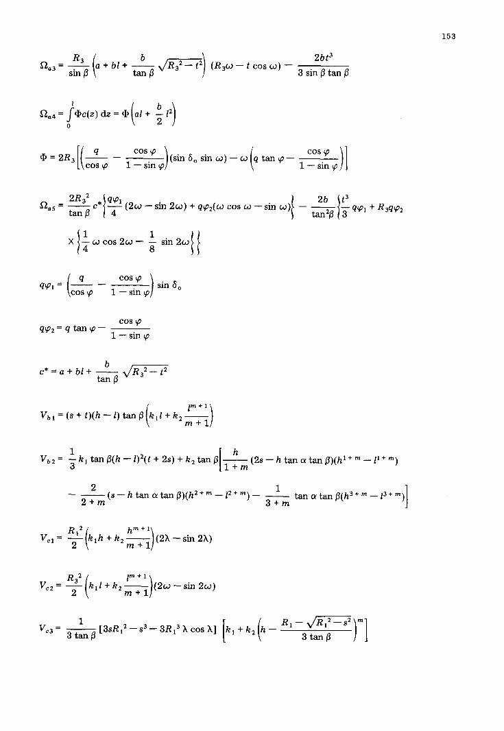
153
aa3= R3 sin 0
2bt3 (R,w - t cos o) -
3 sin /3 tan /3
@=2R, -Z-- [i
‘OS ’ cos Lp 1 - sin cp 1
(sin 6, sinw)-cd i q tancp-
cos cp
1 - sin cp 11
sin 2w) + 4+~7~(w cos w - sin 0) - -
i cd cos 2w - $ sin 2w
( 4 cos q w1= - -
1 - sin q 1 sin 8,
cos cp
w2=4tancp- cos $0
1 - sin cp
c *=a+bl+
v,, = (s + t)(h
Vb2 = + k 1 tan /3(h - 1)2( t + 2s) + k, tan j3 &(2s--h tancrtan(3)(h1+“-11+m)
This energy equation has to be solved to find the critical diameter, depending on prism geometry, bin geometry and material properties. To solve this equation, a large amount of calculations is required. For every prism, a critical diameter can be determined. The smallest of the critical diameters thus found is the least upper bound to the actual critical diameter.