Theory and optical implementation of the geometrical approach of multiple circular harmonic filters Lixin Shen, Yunlong Sheng, and Guy Pre ´ mont The circular harmonic filter contains only one component of the image. Its discrimination capability has been questionable. The geometrical approach of multiple circular harmonic filters uses relative locations of the correlation peaks as the rotation-, shift-, and intensity-invariant features for pattern recognition. Each feature depends on the entire image. This approach has a good discrimination capability. Optical real-time implementation of the on-axis continuous phase-only circular harmonic filters by the use of a commercial liquid-crystal television is shown. A harmonic analysis shows that the phase-mostly filter can tolerate coupled amplitude modulation at the acceptable expense of the output signal-to-noise ratio. An optical experiment of the geometrical approach of multiple circular harmonic filters for a multiple-image input is described. The cross-correlation peaks between the individual filters and the clutter are eliminated, because they are not in good locations. Key words: Circular harmonic filter, optical real-time phase-mostly correlator. 1. Introduction The circular harmonic 1CH2 filter 1 1CHF2 has the unique feature of continuous full-range in-plane rota- tion invariance. To achieve the full-range rotation invariance, a composite filter might need to combine 72 images, each rotated by 5°. 2 In practice the performance of the composite filter is degraded with increasing of the number of combined images. The CHF contains only one CH component of the image. Its correlation peak represents recognition of only one CH order in the input image. An ap- proach of multiple CHF’s was proposed 3,4 that uses the center-correlation intensities of the CHF’s as the features for statistical classification. Danielsson made a comment that there is a host of other images that can give the same center-correlation intensities with the given set of CHF’s. The CHF’s cannot discriminate against those images. 5,6 Another ap- proach is the lock-and-tumbler 1LAT2 filter, which is a linear combination of multiple CH components. The LAT filter is designed with an iterative technique such that the center-correlation intensity is constant when the filter is rotated. 7 However, the center correlation is not necessarily a peak. Application of the LAT filter therefore requires rotating the filter and making an exhaustive search in the correlation plane for a point whose intensity is constant during the rotation of the filter. The geometrical approach of multiple CHF’s is different from the above linear schemes. 8 It uses a filter bank of usually 5–10 CHF’s of different orders of the reference image. The coordinates of the correla- tion peak of the individual CHF and the distances between the peak points are taken as the rotation- invariant features for pattern recognition. These distance features are nonlinear parameters of the image. This approach combines optical correlation for feature extraction and statistical pattern recogni- tion in order to achieve a good discrimination capabil- ity. In this paper we present the theory and the optical implementation of this approach. We prove that, although the correlation peak intensity of a CHF depends on only one CH component, the peak locaton depends on all CH orders of the image. The on-axis continuous phase-only CHF is imple- mented on a commercial liquid-crystal television 1LCTV2. The on-axis correlation has high light effi- ciency 9 and effectively utilizes the space–bandwidth product 1SBWP2 of the spatial light modulator 1SLM2, whereas the SBWP is very limited in electrically The authors are with the Centre d’Optique, Photonique et Laser, Departement de Physique, Universite ´ Laval, Ste-Foy, Que ´bec, Canada G1K 7P4. Received 20 October 1994; revised manuscript received 20 Octo- ber 1994. 0003-6935@95@204004-09$06.00@0. r 1995 Optical Society of America. 4004 APPLIED OPTICS @ Vol. 34, No. 20 @ 10 July 1995
Transcript
Theory and optical implementationof the geometrical approachof multiple circular harmonic filters
Lixin Shen, Yunlong Sheng, and Guy Premont
The circular harmonic filter contains only one component of the image. Its discrimination capability hasbeen questionable. The geometrical approach of multiple circular harmonic filters uses relativelocations of the correlation peaks as the rotation-, shift-, and intensity-invariant features for patternrecognition. Each feature depends on the entire image. This approach has a good discriminationcapability. Optical real-time implementation of the on-axis continuous phase-only circular harmonicfilters by the use of a commercial liquid-crystal television is shown. A harmonic analysis shows that thephase-mostly filter can tolerate coupled amplitude modulation at the acceptable expense of the outputsignal-to-noise ratio. An optical experiment of the geometrical approach of multiple circular harmonicfilters for amultiple-image input is described. The cross-correlation peaks between the individual filtersand the clutter are eliminated, because they are not in good locations.Key words: Circular harmonic filter, optical real-time phase-mostly correlator.
1. Introduction
The circular harmonic 1CH2 filter1 1CHF2 has theunique feature of continuous full-range in-plane rota-tion invariance. To achieve the full-range rotationinvariance, a composite filter might need to combine72 images, each rotated by 5°.2 In practice theperformance of the composite filter is degraded withincreasing of the number of combined images.The CHF contains only one CH component of the
image. Its correlation peak represents recognitionof only one CH order in the input image. An ap-proach of multiple CHF’s was proposed3,4 that usesthe center-correlation intensities of the CHF’s as thefeatures for statistical classification. Danielssonmade a comment that there is a host of other imagesthat can give the same center-correlation intensitieswith the given set of CHF’s. The CHF’s cannotdiscriminate against those images.5,6 Another ap-proach is the lock-and-tumbler 1LAT2 filter, which is alinear combination of multiple CH components.The LAT filter is designed with an iterative technique
The authors are with the Centre d’Optique, Photonique et Laser,Departement de Physique, Universite Laval, Ste-Foy, Quebec,Canada G1K 7P4.Received 20 October 1994; revised manuscript received 20 Octo-
such that the center-correlation intensity is constantwhen the filter is rotated.7 However, the centercorrelation is not necessarily a peak. Application ofthe LAT filter therefore requires rotating the filterand making an exhaustive search in the correlationplane for a point whose intensity is constant duringthe rotation of the filter.The geometrical approach of multiple CHF’s is
different from the above linear schemes.8 It uses afilter bank of usually 5–10 CHF’s of different orders ofthe reference image. The coordinates of the correla-tion peak of the individual CHF and the distancesbetween the peak points are taken as the rotation-invariant features for pattern recognition. Thesedistance features are nonlinear parameters of theimage. This approach combines optical correlationfor feature extraction and statistical pattern recogni-tion in order to achieve a good discrimination capabil-ity. In this paper we present the theory and theoptical implementation of this approach. We provethat, although the correlation peak intensity of a CHFdepends on only one CH component, the peak locatondepends on all CH orders of the image.The on-axis continuous phase-only CHF is imple-
mented on a commercial liquid-crystal television1LCTV2. The on-axis correlation has high light effi-ciency9 and effectively utilizes the space–bandwidthproduct 1SBWP2 of the spatial light modulator 1SLM2,whereas the SBWP is very limited in electrically
addressed SLM’s. The twisted nematic LCTV canprovide continuous phase modulation. As a phasemodulator it suffers, however, from coupled ampli-tude modulation and phase mismatching 1a maxi-mum phase modulation of smaller than 2p2. Thephase-mostly filter is a phase-only filter 1POF2 en-coded on a SLMwith slightly coupledmodulations.10,11We provide a harmonic analysis that shows that thecoupled-mode SLM can provide the exact POF re-sponse. The coupled amplitude modulation and thephase mismatching contribute to the noise that isspread out in the correlation output. We show thehigh-input signal-to-noise ratio 1SNR2 of the phase-mostly filter.Juday12 and Fan and Goodman13 proposed optimal
filters for the coupled-mode SLM’s. In those algo-rithms the filter value at each pixel is chosen tomaximize one of the selected metrics: correlation-peak intensity, SNR, and others. Unfortunately, theoptimal filter algorithms are limited to the matchedfilter that detects a single object. The CHF hasadditional constraints on the filter values. The CHkernel function exp1 jmf2 must be well preserved inorder to guarantee full-range rotation invariance.Hence there is no degree of freedom for the filterphase, which is required for the optimization.Juday et al. recently showed laboratory results14 by
using a LCTV in a high-contrast mode that had a fullrange of amplitude modulation and only ,2p@3 rangephase modulation. In this case, the optimized filtershave better performances than those of the POF.However, a POF of 2p@3 phase range is far from thePOF originally proposed by Horner and Gianino.9We experimentally optimize the phase-mostly filterby rotating the polarizer and the analyzer and byusing the in situ measurement of the LCTV15 tominimize the coupled amplitude modulation. For aSLM that has the full range of 2p phase modulationand a small variation of amplitude, the benefit fromthe optimization would be small. When the SLM isperfectly phase only, the optimal maximum correla-tion filter is simply the POF.12In Section 2 we review the theory of the CHF.
Following the discussion of Danielsson and Arse-nault, we show that the two-dimensional 12-D2 correla-tion of a CHF contains information about the entireinput image and that this information can be used inthe geometrical approach of multiple CHF’s. In Sec-tion 3 we present the theory and the experiment of thephase-mostly filter. Experimental results of the opti-cal CHF’s are given in Section 4.
2. Theory of the Circular Harmonic Filter
The impulse response of the CHF is one of the CHcomponents of the image:
fr1x, y2 5 fm1r2exp1 jmu2, 112
where j 5 Œ21, m 5 0, 61, 62, . . . , and fm1r2 is the
CH function of the image f 1r, u2, where
fm1r2 51
2p e0
2p
f 1r, u2exp12 jmu2du. 122
The autocorrelation of the CHF at the center of thecorrelation plane x8 5 0 and y8 5 0 is equal to theenergy of the CH component,
Cm10,02 5 2p e0
`
0 fm1r2 02rdr, 132
whose intensity 0Cm10,02 02 is rotation invariant.1 TheCHF is designed with a properly chosen expansioncenter so that the center correlation is a peak.16,17
A. Information Content
The correlation peak of one CHF represents therecognition of only one CH order in the input image.Its intensity 0Cm10,02 02 depends on only the mth CHorder and is not affected by any changes of other CHorders, because of the orthogonality of the CH expan-sion. In principle, there is an infinity of images thatcan yield the same center-correlation intensities witha given set of CHF’s of the order of m1, m2, . . . , mN.Those images may be built up of the same CHcomponents of the order of m1, m2, . . . , mN as that ofthe CHF bank, but of different CH components of theorder of m fi m1, m2, . . . , mN. Furthermore, anyrotations of any CH components by arbitrary anglescan yield new images that still give the same center-correlation intensities. Danielsson observed5 thatthe CHF’s do not discriminate well against thoseimages. Arsenault argued6 that most images gener-ated by rotating and changing the CH components areartificial images. It is unlikely that those imageswere in the input scene and were confused with thetarget. This discussion raised a fundamental ques-tion on the discrimination capability of the CHF.In fact, Danielsson’s comment is true when one
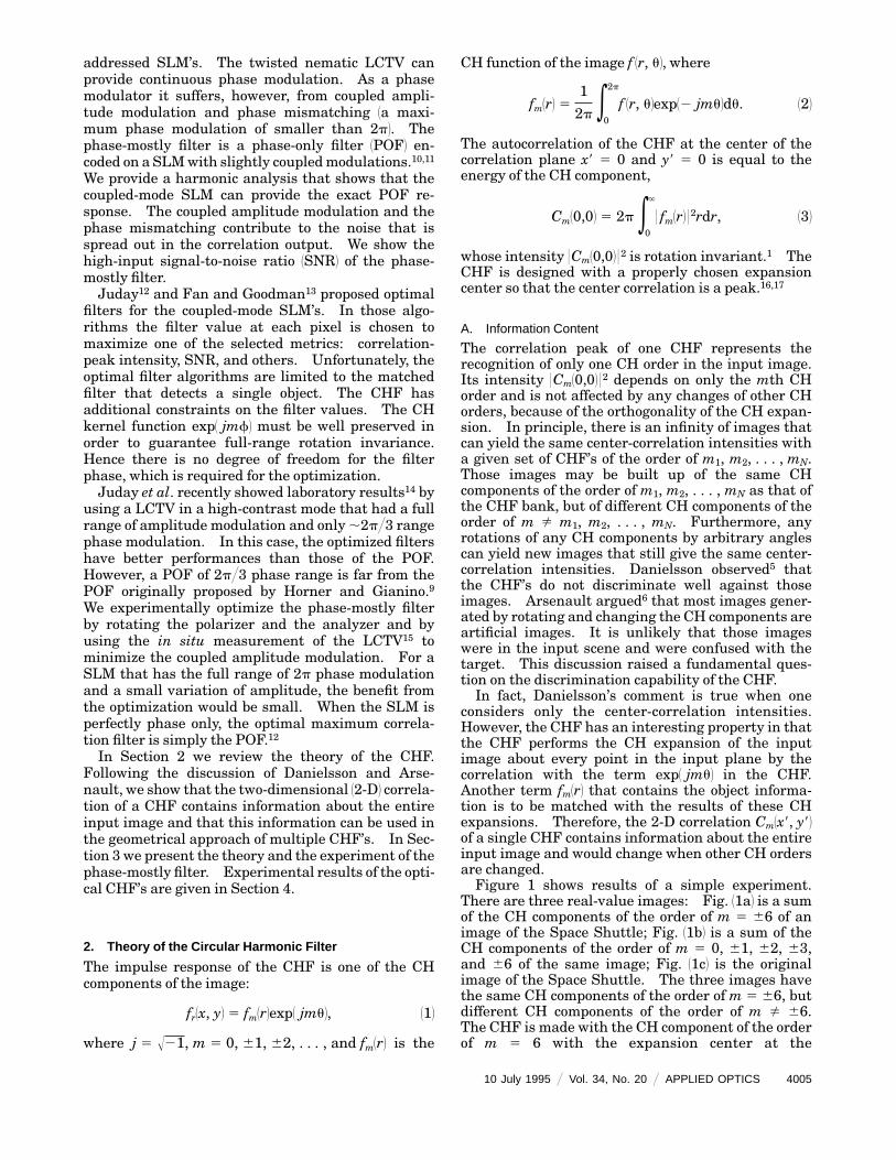
considers only the center-correlation intensities.However, the CHF has an interesting property in thatthe CHF performs the CH expansion of the inputimage about every point in the input plane by thecorrelation with the term exp1 jmu2 in the CHF.Another term fm1r2 that contains the object informa-tion is to be matched with the results of these CHexpansions. Therefore, the 2-D correlation Cm1x8, y82of a single CHF contains information about the entireinput image and would change when other CH ordersare changed.Figure 1 shows results of a simple experiment.
There are three real-value images: Fig. 11a2 is a sumof the CH components of the order of m 5 66 of animage of the Space Shuttle; Fig. 11b2 is a sum of theCH components of the order of m 5 0, 61, 62, 63,and 66 of the same image; Fig. 11c2 is the originalimage of the Space Shuttle. The three images havethe same CH components of the order of m 5 66, butdifferent CH components of the order of m fi 66.The CHF is made with the CH component of the orderof m 5 6 with the expansion center at the
origin. Figures 11d2–11f 2 show the correlation outputs.Because the three images have the same CH compo-nents ofm 5 66, the three correlations have the sameintensity at the center. If one considers only thecenter-correlation intensities, the CHF designed torecognize the image of Fig. 11a2 is not able to discrimi-nate against the other two images. However, outsidethe center, the three correlation functions are verydifferent. Figures 11e2 and 11f 2 contain sidelobes thatare much higher than the center-correlation peak.
B. Two-Dimensional Correlation Output
To obtain an analytical expression of the 2-D correla-tion Cm1x8, y82we write it in the Fourier plane as
Cm1x8, y82 5 ee2`
`
F1u, v2Fr*1u, v2
3 exp3 j2p1ux8 1 vy824dudv, 142
where F1u, v2 is the Fourier transform of the inputimage f 1x, y2, Fr1u, v2 is the CHF in the Fourier plane,and
Fr*1u, v2 5 Fm*1r2exp12 jmf2. 152
The Fourier transform F1u, v2 can be written in a
Fig. 1. 1a2, 1b2, 1c2, images that have the same CH component of theorder of m 5 6 but different components of other orders; 1d2, 1e2, 1f 2,the corresponding correlations with a CHF of the order of m 5
6. The intensities of the center correlations are the same, but the2-D correlation functions are different.
where x 5 r cos u, y 5 r sin u, u 5 r cos f, v 5 r sin f,and Jm12prr2 is the mth-order Bessel function of thefirst kind. According to Eq. 162 the CH function Fm1r2of F1u, v2 is
Fm1r2 5 2p12 j2m e0
`
fm1r2Jm12prr2rdr, 172
that is, the mth-order Hankel transform18 of the CHfunction fm1r2 of the image. Substituting Eq. 152 intoEq. 142, we see that the term exp12 jmf2 performs theCH expansion about the origin u 5 0, v 5 0 ofF1u, v2exp3 j2p1ux8 1 vy824, which is the Fourier trans-form of the input image shifted to 12x8, 2y82, and theCm1x8, y82 is the inner product between the resultantCH function and the term Fm*1r2 of the filter.Let F1u, v; x8, y82 and F1u, v; 0, 02 be the Fourier
transforms of the image shifted to 12x8, 2y82, and thenonshifted image. In the polar coordinate systemwehave
where x8 5 r8 cos u8, y8 5 r8 sin u8. Because the CHexpansion of the phase-shift factor exp32 j2prr8cos1u8 2 f24 is
1
2p e0
2p
exp32 j2prr8 cos1u8 2 f24exp12jkf2df
5 Jk12prr82exp3 jk1u8 1p
224 , 192
the CH expansion of F1r, f; r8, u82 then yields
Fm1r; r8, u82 51
2p e0
2p
F1r, f; 0, 02
3 exp32 j2prr8 cos1u8 2 f24
3 exp12 jmf2df
5 on52`
`
Fn1r; 0, 02Jm2n12prr82
3 exp32 j1m 2 n21u8 1p
224 . 1102
Themth-order CH function, Fm1r; r8, u82, of the Fouriertransform of the image shifted to the point 1r8, p 1 u82is a linear combination of all the CH functions Fn1r;0, 02 with 2` # n # ` of the Fourier transform of thenonshifted image. The coefficients in the combina-tion depend on r8 and u8.The proper expansion center of the CHF is deter-
mined by Eq. 1102. The proper center is a point on theimage such that, when it is the expansion center of aCHF, the 2-D autocorrelation function of this CHFwill have a peak at that point. The condition for theproper center 1rp, up2 is that the energy of the CH order,e 0Fm1r; rp, up20 02rdr, developed about 1rp, up2, is maxi-mum.17 The solution for the proper center from Eq.1102 should be found numerically.16 According to Eq.1102 the location of the proper center, which is also thelocation of the correlation peak, of one CHF dependson the CH functions Fn1r; 0, 02 of all orders of theimage.The proper centers of different CH orders m are at
different locations. They constitute a geometricalfeature pattern of the image. The pattern is shiftedand rotated with the input image. Its shape and thedistances between the proper centers are shift, rota-tion, and intensity invariant. The distance featuresare nonlinear parameters of the input image. Theydepend on not only the CH orders included in the CHFbank, but also on all other CH orders.On substituting Eqs. 1102 and 152 into Eq. 142, we
obtain the 2-D correlation function of the CHF:
Cm1r8, u82 5 2p e0
`
5 on52`
`
Fn1r; 0, 02Jm2n12prr82
3 exp32 j1m 2 n21u8 1p
22463 Fm*1r; 0, 02rdr. 1112
Because the Bessel function Jm2n102 5 0 form fi n andJm2n102 5 1 for m 5 n, at the center r8 5 0 and u8 5 0,Eq. 1112 becomes
Cm10, 02 5 2p e0
`
0Fm1r; 0, 02 02rdr, 1122
which is equivalent to that given by Eq. 132 anddepends on only themth CH order. However, accord-ing to Eq. 1112, the 2-D correlationCm1r8, u82 depends onthe CH functions Fn1r; 0,02 of all orders 2` # n # `.This conclusion is understandable. In fact, for anykind of spatial filters, when the filter is given, the 2-Dcorrelation output depends uniquely on the inputimage. The question is how to utilize the informa-tion contained in the 2-D correlation. In the case ofthe CHF this property is used to determine thelocation of the correlation peak.
C. Geometrical Approach of Multiple Circular HarmonicFilters
To determine the relative locations of the correlationpeaks, multiple CHF’s of different orders of thereference image have to be used. The CHF’s aregenerated about their respective proper centers.The filter bank usually consists of 5–10 CHF’s. Thecoordinates of the correlation peaks of the individualCHF’s are taken. The distances between the correla-tion peaks are used as the rotation-, shift-, andintensity-invariant features for statistical patternrecognition in multidimensional feature space. Theprototype distance vector is determined in the filterdesign.Assume that the filter bank consists of the CHF’s of
the order of m1, m2, . . . , mN and that a deterministicpattern classifier with the minimum distance crite-rion is used. The probability for clutter in the inputscene to yield a high cross-correlation peak with theCHF is small.6 The probability for the clutter toyield two correlation peaks with the CHF’s of theorder of mi and mj at a distance equal to di, j of theprototype vector is even smaller. Let pi j be thisprobability. Assume also that all the events areindependent. Then the probability of false detectionwith the geometrical approach of multiple CHF’s isthe probability of the joint events:
p12p13p23 . . . P1N212N. 1132
This probability is very small. Increasing the num-berN of the multiple CHF’s can increase the certaintyof the detection and reduce the probability of falsealarm.
3. Optical Phase-Mostly Filters
Optical implementation of the geometrical approachof multiple CHF’s requires a real-time SLM. We usethe LCTV to encode the phase-only CHF. Let usanalyze the behavior of this optical filter.
A. Diffraction of the Phase-Mostly Filter
Assume that a POF, exp3 jf1u, v24 with 0 # f # 2p, isgenerated in the computer and that the phase func-tion f1u, v2 is fed to the coupled-mode modulationSLM. The SLM provides the phase modulationf81u, v2 fi f1u, v2 with the coupled amplitude modula-tionA1u, v2. Both the phase and the amplitudemodu-lations are controlled by a single electronic videosignal, which is proportional to f1u, v2. The ampli-tude A1f2 and phase f81f2 are functions of f that aredetermined by the modulation characteristics of theSLM. The optical filter, F81u, v2 5A1u, v2exp3 jf81u, v24,on the SLM is a periodic funciton of f1u, v2 of period 2p. We expand F81u, v2 into the Fourier series withrespect to f1u, v2;
are the Fourier transforms of A1f2exp3 jmf81f24 withrespect to the filter phase f1u, v2 and are independentof f. The first-order harmonic, exp3 jmf1u, v24withm5 1 in the harmonic expansion of Eq. 1142, is the truePOF. Other terms of m fi 1 are associated with thecoupled amplitude modulation and the phase mis-matching. The termm5 0 gives a central spot in theimpulse response of the filter. The term m 5 21gives an inverted POF impulse response. The im-pulse responses of the higher-order terms,exp3 jmf1u, v24 with 0m 0 $ 2, corresponding to theconvolution, the double, triple, and multiple convolu-tions, and the correlations among the impulse re-sponses of the POF. Because no spatial frequencycarrier is used in the POF, all the diffraction ordersare superimposed on axis, contributing to the noise inthe impulse response of the filter.In an approximation in which the phase modula-
tion is linear to the electronic signal, f81u, v2 5 cf1u, v2,where 0 # c # 1 is the phase mismatching factor to 0# f8 # 2pc, Eq. 1152 becomes
am 51
2p e0
2p
A1f2exp3 j1m 2 c2f4df. 1162
When the SLM is perfectly phase only, c 5 1 andA1f2 5 1, then a1 5 1 and am 5 0 for all m fi 1, theoptical filter F81u, v2 would be the POF, exp3 jf1u, v24.Otherwise, the coefficient a1 of the POF term iscomplex valued and 0a1 0 # 1.The energy distribution among the diffraction or-
ders depends on the coefficients 0am 02. As an ex-ample,10 when the maximum phase modulation is1.4p and the coupled amplitude varies from 1 to 0.5,the POF term takes ,68% of the energy, the zeroorder takes ,21%, and the rest 111%2 goes to otherorders. The POF term is dominant in energy. Aftera careful adjustment of the operating curve, the LCTVused in this paper has much better performance thanthat shown in the example above.In an optical correlator the noise owing to diffrac-
tion orders of m fi 1 of the phase-mostly filter isspread out in the correlation plane. The zero-orderspot in the phase-mostly filter impulse response yieldsan image of the input scene. Other high-order termsyield correlations between the input image and themultiple convolutions and the correlaitons of the POFresponses. Because the on-axis POF yields a verybright correlation peak, the SNR of the correlationoutput of the phase-mostly filter is high, as shownbelow.
B. Experimental Demonstration
The LCTV was one panel in the Epson Crystal Imagevideo projector that had a 1 in. 3 1 in. 12.54 cm 3 2.54
cm2 aperture and 220 3 320 pixels. To obtain thephase-mostly modulation, the brightness control volt-age was turned to minimum. The LCTV was illumi-nated with a parallel He–Ne laser beam. We rotatedthe polarizer and the analyzer in front and in back ofthe LCTV until the zero-order spot in the filterimpulse response was minimum and the correlationpeak was high and noise was low. In this condition,the beam emerging from the LCTV was approxi-mately linearly polarized. The phase modulationwas measured with a wedge shear plate interferome-ter.15 It is approximately linear to the gray level.The maximum phase shift is 2.7p with l 5 0.633 µmfor themaximum gray level of 255. We used then thegray level in the range from 0 to 186 for the 2p rangephase modulation. Within this range of gray levels,the coupled amplitude modulation ranges from ,0.95to ,0.87, as shown in Fig. 2.Figure 31a2 shows the phase-mostly matched spa-
Fig. 2. Experimental measurements for 1a2 phase 1b2 amplitudemodulation as a function of the gray level. Curve 112, analyzerparallel to the polarization of the output beam; curve 122, analyzerperpendicular to the polarization of the output beam.
tial filter on the LCTV observed through an analyzerparallel to the approximately linear polarization ofthe beam emerging from the LCTV. Apparently, thefilter is uniform in intensity because the coupledamplitudemodulation is small and the contrast is low.Then we rotated the analyzer by 90°. The polariza-tion component in this direction was very weak inintensity and was modulated by the complementarycoupled amplitude modulation. The contrast of theamplitude pattern was increased, as shown in Fig.31b2. The total energy of the image shown in Fig. 31a2,which contains the component of the 2p range phasemodulation, is measured to be 16 times higher thanthat in Fig. 31b2 of the orthogonal polarization. Thisexperiment demonstrates thephase–amplitude coupled modulation in the phase-mostly filter.
4. Optical Phase-Mostly Circular Harmonic Filters
We now encode the phase-only CHF’s on the LCTV.The property of the phase-only CHF’s19,20 in terms ofthe information content is similar to that of the CHF.Only the proper center should be determined fromEq.1102 for maximizing e 0Fm1rp, up2 0rdr.
A. Rotation-Invariant Correlation
The on-axis optical correlator, shown in Fig. 4, is aclassical 4-f correlator that has two conjugate filter
Fig. 3. Phase-mostly filter on the LCTV observed through ananalyzer 1a2 parallel to the polarization of the output beam, 1b2perpendicular to polarization of output beam. The filter is amatched spatial filter for the Space Shuttle.
Fig. 4. Real-time optical correlator for implementaiton of thegeometrical approach of multiple CHF’s. F.T., Fourier trans-form.
planes. The input image is on a photographic film,which could be replaced by an amplitude modulationLCTV. An afocal imaging system reduces the size ofthe input such that the Fourier transform of the inputimages is matched to the LCTV in size. The twoFourier lenses have the focal length f 5 300 mm.Because the output beam of the LCTV is approxi-mately linearly polarized, the analyzer behind theLCTV was removed in the optical correlator experi-ments.A key issue in the optical implementation of the
CHF is that the angular sampling rate decreases withthe decrease of the radial coordinate r. The CHF’s,especially those of high orders, are subsampled aroundthe origin of the Fourier plane. The subsamplingerror is amplified in the case of the phase-only CHF:the conventional CHF in the Fourier plane has itsmodulus 0Fm102 0 5 0 at the origin.19 The phase-onlyCHF has 0Fm1r2 0 5 1. Not only the high frequenciesbut also the low frequencies around the origin areemphasized in the phase-only CHF. Because mostenergy of an image is concentrated in the low-frequency band, the subsampling error in the low-frequency band can jeopardize the rotation invari-ance of the filter. Our solution is to introduce a dcblock disk on the optical axis in the Fourier plane.Blocking the low frequencies does not affect thediscrimination capability of the CHF’s. The size ofthe dc block disc was optimized experimentally andwas equal to 7 pixels in radius. Figure 5 shows thephase-mostly CHF’s on the LCTV and their impulseresponses. The filters were observedwith themethodmentioned in Subsection 3.B. The central spot inthe impulse responses is typical for the phase-mostly
Fig. 5. Optical phase-mostly CHF’s on the LCTV without 1firstrow2 and with 1third row2 a dc block and their optical impulseresponses 1second and fourth rows2. From left to right: m 5 4,6, 12.
filters and is owing to the coupled amplitude modula-tion. The impulse responses of the CHF’s with the dcblock disk are similar to those without the disk.Figure 6 shows the optical correlation outputs.
When the input image was rotated continuouslyabout the optical axis, the on-axis correlation outputwas simply rotated about the optical axis. The corre-lation-peak intensity was kept constant during therotation. We use the peak-to-correlation deviation1PCD2 ratio,21
PCD 53I1x, y24max
1 ox, y51
N
5I1x, y2 2 E3I1x, y246221@21172
as ameasure of the filter performance. The values ofPCD’s of the optical phase-mostly CHF’s of theorder of m 5 2, . . . , 12 ranged from 25 to 35. Thosevalues are comparable with those obtained by thecomputer simulation of the ideal phase-only CHF’s.
Fig. 6. Optical correlation outputs of the phase-mostly CHF’s:1a2 From left top to bottom right: Input image, outputs with m 5
2, 3, . . . , 12; 1b2 correlations of the CHF’s of m 5 2 and 9 witharbitrarily rotated input images; 1c2, 1d2 three-dimensional plots ofthe correlations of the CHF’s of 1c2m 5 2, 1d2m 5 9.
B. Geometrical Approach of Multiple CircularHarmonic Filters
The input scene contains four images, as shown inFig. 7. The image of the Space Shuttle is to berecognized. The two images of aircraft and the im-age of the Space Shuttle with its cargo bin opened areto be discriminated. Phase-only CHF’s of seven arbi-trary chosen orders m 5 2, 3, 6, 7, 9, 10, and 12 weregenerated for the image of the Space Shuttle. Theseven CHF’s were encoded sequentially on the LCTV.Figure 7 shows the correlation of the CHF’s of m 5 2,6, and 9. When the input scene was rotated to anarbitrary angle, the correlations were rotated withthe input. In the outputs of individual CHF’s thereare many high cross-correlation peaks generated bythe clutter, which must be eliminated.The multiple-image input yields many correlation
peaks of different intensities. A postprocessing algo-rithm was designed to determine the local peaks, tocluster the peaks, and to identify the peak pattern by
Fig. 7. Top row: Input scenes and rotated input scene. Eachcontains four images. Their names are: top left, Nav000; topright, Nav1; bottom left, X29; bottom right, Light. Bottomrow: corresponding correlation outputs with the CHF’s of m 5 2,6, and 9 for Nav000.
the use of a priori knowledge of the size of the targetand its feature pattern of proper centers. The algo-rithm can detect the target even if the cross-correlation peaks are higher than the autocorrelationpeaks.First, we determined the first maximum in the
correlation of the CHF with m 5 2, which containsmore energy and is more robust to noise.22 Weerased the correlation values inside a circle centeredat the first maximum. The radius of the circle isequal to the half of the size of the image of the SpaceShuttle. Then we determined the second maximumin the remainder of the correlation values and erasedthe values inside a circle of the same size centered atthe second maximum. The process was repeateduntil the intensity of the last maximum was below athreshold. In the experiment, we picked up five localcorrelation peaks. The intensity of the first peakwas ,230 and that of the fifth peak was ,30. Thosepeaks could include the autocorrelation peaks fromthe target and the cross-correlation peaks from theclutter and background.The second step is seeking the correlation peaks of
other CHF’s. For the target, the distance betweenthe peaks of the orders of m 5 2 and m 5 3 must beequal to d2,3, which is known in the filter design. Wedefined a circle of radius d2,3 1 e centered at each ofthe five peaks of the CH correlation of m 5 2, wheree 5 2Œ2 pixels is the tolerance for the distance error.We loaded up the CH correlation of the order ofm 5 3and determined one local maxima on each of the fivecircles. Then we defined a circle of radius of d2,4 1 e,still centered at each of the five peaks of the CHcorrelation of m 5 2. We loaded up the CH correla-tion of m 5 4 and determined a local peak on each ofthose circles. The process was repeated for all thecorrelations of the CHF’s. We then obtained fiveclusters of local peaks.The last step is matching the obtained peak clus-
ters with the reference feature pattern of propercenters of the target by the use of the distancesbetween each pair of peaks. The application of theseven CHF’s and the postprocessing yielded 21 dis-tances for each cluster of peak points. Table 1 showsthe wrong distances among the 21 distances of the fiveclusters. Ten arbitrary rotated input scenes weretested. The image of the Space Shuttle 1Nav0002yielded an average of 0.7 wrong distance. The threepeak clusters from the other three input images1Nav1, Light, and X292 yielded averages of 9.2–10.3wrong distances. The fifth peak cluster from thebackground noise yielded an average of 10.7 wrongdistances. The Space Shuttle was therefore identi-fied. The cross-correlation peaks from other imagesand the background were eliminated without causinga false alarm.
C. Operation Speed
The LCTV can operate at the TV rate. The opera-tion speed of the optical geometrical approach ofmultiple CHF’s is the TV rate divided by the number
of the CHF’s in the filter bank. This number de-pends on the complexity of the input scene. In theoptical experiments, 5–7 CHF’s can yield satisfactoryresults.The postprocessing speed depends on the number of
the CHF’s and the number of the local correlationpeaks above the threshold in the case of the multiple-image input. In the above experiment, the postpro-cessing needs ,0.3 s in the Sun SPARC Station IPXfor processing the seven correlation outputs of 200 3200 pixels for the seven CHF’s with the four imageinput scenes. Thus the actual operation speed isabout 3–4 recognitions per second. It is possible tospeed up the operation by improving the electronicshardware and software.
5. Conclusion
We have proved that the peak location of a CHFdepends on all the CH orders. We use multipleCHF’s to determine the relative locations of the CHFcorrelation peaks. The distances between the peaksare nonlinear parameters of the image and are therotation-, shift-, and intensity-invariant representa-tive image features. They depend on not only the CHorders used of the multiple CHF bank, but also on allother CH orders of the image.The harmonic analysis on the phase-mostly filter
shows that the phase-mostly filters provide the POFresponse and tolerate the coupled amplitude modula-tion and the phase mismatching at an acceptableexpense of the output SNR. The optical implementa-tion with seven CHF’s and a multiple-image inputscene shows a good discrimination capability. Thehigh cross-correlation peaks from clutter and back-ground in the input scene are eliminated withoutcausing false alarms.
References1. Y. N. Hsu, H. H. Arsenault, and G. April, ‘‘Rotation-invariant
digital pattern recognition using circular harmonic expan-sion,’’ Appl. Opt. 21, 4012–4015 119822.
2. D. Casasent and R. Ravichandran ‘‘Advanced distortion-invariant minimum average correlation energy 1MACE2 fil-ters,’’ Appl. Opt. 31, 1109–1116 119922.
Table 1. Total Number of Wrong Distances in the Clusters of Local PeaksExtracted from Seven CH Correlations a
aFour clusters correspond to four input images. Another clusteris from background noise. The input scene is shown in Fig.7. Ten orientations of the input scene were tested.
3. H. H. Arsenault and C. Belisle, ‘‘Contrast-invariant patternrecognition using circular harmonic components,’’ Appl. Opt.24, 2072–2075 119852.
4. R. Wu and H. Stark, ‘‘Rotation-invariant pattern recognitionusing a vector reference,’’ Appl. Opt. 23, 838–840 119842.
5. P. E. Danielsson, ‘‘A comment on rotation-invariant patternrecognition using circular harmonic expansion,’’ Appl. Opt. 28,1613–1614 119892.
6. H. H. Arsenault, ‘‘Rotation-invariant digital pattern recogni-tion using circular harmonic expansion: author’s reply tocomments,’’ Appl. Opt. 28, 1614–1615 119892.
7. G. F. Schils and D. W. Sweeney, ‘‘Iterative technique for thesynthesis of optical-correlation filters,’’ J. Opt. Soc. Am A 3,1433–1442 119862.
8. Y. Sheng and H. H. Arsenault, ‘‘Object detection from a realscene using the correlaiton peak coordinates of multiplecircular harmonic filters,’’ Appl. Opt. 28, 245–249 119892.
9. J. L. Horner and P. D. Gianino, ‘‘Phase-only matched filtering,’’Appl. Opt. 23, 812–816 119842.
10. Y. Sheng and G. Paul-Hus, ‘‘Optical on-axis imperfect phase-only correlator using liquid crystal television,’’ Appl. Opt. 32,5782–5785 119932.
11. D. Roberge and Y. Sheng, ‘‘Optical implementation of thephase-only composite filter using liquid crystal television,’’ inOptical Pattern Recognition V, D. P. Casasent and T.-H. Chao,eds., Proc. Soc. Photo-Opt. Instrum. Eng. 2237, 196–203119942.
12. R. D. Juday, ‘‘Optimal realizable filters and the minimumEuclidean distance principle,’’ Appl. Opt. 32, 5100–5111 119932.
13. M. W. Fan and J. W. Goodman, ‘‘Optimal maximum correla-
tion filter for arbitrarily constrained devices,’’ Appl. Opt. 28,3362–3366 119892.
14. R. D. Juday, R. S. Barton, and S. E. Monroe, ‘‘Experimentalcorrelator results with coupled modulators and advancedmetrics,’’ in Photonics for Processors, Neural Networks, andMemories II, J. L. Horner, B. Javidi, W. J. Miceli, and S. T.Kowel, eds., Proc. Soc. Photo-Opt. Instrum. Eng. 2297, 76–88119942.
15. L. Goncalves, D. Roberge, and Y. Sheng, ‘‘Programmableoptical phase-mostly holograms with coupled-mode modula-tion liquid crystal television,’’ Appl. Opt. 34, 1944–1950 119952.
16. G. Premonet and Y. Sheng, ‘‘Fast determination of the propercenter for the circular harmonic filter using the simulatedannealing,’’ Appl. Opt. 32, 3116–3121 119932.
17. Y. Sheng and H. H. Arsenault, ‘‘Method for determiningexpansion centers and predicting sidelobe levels for circular-harmonic filters,’’ J. Opt. Soc. Am.A 4, 1793–1797 119872.
18. R. N. Bracewell, The Fourier Transform and Its Applications,2nd ed. 1McGraw-Hill, NewYork, 19862, Chap. 11.
19. L. Leclerc, Y. Sheng, and H. H. Arsenault, ‘‘Rotation-invariantphase-only and binary phase-only correlation’’ Appl. Opt. 28,1251–1256 119892.
20. J. Rosen and J. Shamir, ‘‘Circular harmonic phase filters forefficient rotation-invariant pattern recognition,’’ Appl. Opt. 27,2895–2899 119882.
21. J. L. Horner, ‘‘Metrics for assessing pattern recognition perfor-mance,’’ Appl. Opt. 31, 165–166 119922.
22. H. H. Arsenault and Y. Cheng, ‘‘Properties of the circularharmonic expansion for rotation-invariant pattern recogni-tion,’’ Appl. Opt. 25, 3225–3229 119862.