THEORY, CONSTRUCTION. AND USE OF THE PHOTOMETRIC INTEGRATING SPHERE By E. B. Rosa and A. H. Taylor ABSTRACT Part I deals with the materials and construction of various spheres, and describes in detail the construction of a reinforced concrete sphere at the Bureau of Standards. It gives tests of the accuracy of integration by this sphere, the absorption of light by the sphere coating and by objects in the sphere, and the effect of the position of lamps. Proper methods of operation are also outlined. Part II gives a fairly complete r^sumd of the general theory of the sphere, with the addition of a considerable amount of new material, showing how to test the accuracy of the sphere, and how to improve the accuracy of integration. It also gives a bibli- ography of the subject. Page Part I : ODnstruction and use 282 1. Introduction 282 2. Mirror integrators 282 3. Ulbricht sphere 283 4. Materials of which spheres have been constructed 283 5. Other types of closed integrators 284 6. Bureau of Standards sphere 285 7. Sphere paint 288 8. Photometric equipment 291 9. Costs of construction 292 10. Advantages of bureau sphere 292 11. Tests of bureau sphere 293 12. Absorption of reflected light by foreign objects 295 13. Reflection factor of sphere coating 296 14. Effect of lamp position 298 15. Selective absorption by the sphere surface 299 16. Method of operation 301 17. Special uses of integrating spheres 304 18. GDnclusion 304 Part II: Theory 305 1 Introduction 305 2 General theory 305 3. Errors of measurement due to screen 307 4. Position and size of screen 309 5. Absorption of light by foreign objects 314 6. Effect of lamp position 315 7. Error of integration of narrow cone of light 317 8. Factors affecting the accuracy of measurement 321 9. Best condition of sphere for certain work 322 10. Classification of bibliography 322 11. Bibliography 322
Transcript
THEORY, CONSTRUCTION. AND USE OF THEPHOTOMETRIC INTEGRATING SPHERE
By E. B. Rosa and A. H. Taylor
ABSTRACT
Part I deals with the materials and construction of various spheres, and describes
in detail the construction of a reinforced concrete sphere at the Bureau of Standards.
It gives tests of the accuracy of integration by this sphere, the absorption of light bythe sphere coating and by objects in the sphere, and the effect of the position of lamps.
Proper methods of operation are also outlined.
Part II gives a fairly complete r^sumd of the general theory of the sphere, with the
addition of a considerable amount of new material, showing how to test the accuracy
of the sphere, and how to improve the accuracy of integration. It also gives a bibli-
ography of the subject.
Page
Part I : ODnstruction and use 282
1. Introduction 282
2. Mirror integrators 282
3. Ulbricht sphere 283
4. Materials of which spheres have been constructed 283
5. Other types of closed integrators 284
6. Bureau of Standards sphere 285
7. Sphere paint 288
8. Photometric equipment 291
9. Costs of construction 292
10. Advantages of bureau sphere 292
11. Tests of bureau sphere 293
12. Absorption of reflected light by foreign objects 295
13. Reflection factor of sphere coating 296
14. Effect of lamp position 298
15. Selective absorption by the sphere surface 29916. Method of operation 301
17. Special uses of integrating spheres 30418. GDnclusion 304
Part II: Theory 3051
.
Introduction 3052
.
General theory 305
3. Errors of measurement due to screen 307
4. Position and size of screen 309
5. Absorption of light by foreign objects 3146. Effect of lamp position 315
7. Error of integration of narrow cone of light 3178. Factors affecting the accuracy of measurement 321
9. Best condition of sphere for certain work 322
10. Classification of bibliography 322
11. Bibliography 322
282 Scientific Papers of the Bureau of Standards {Voi.is
PART I.—CONSTRUCTION AND USE[By E. B. Rosa and A. H. Taylor]
1. INTRODUCTION
In the early history of photometry, as in most of the sciences,
the apparatus was somewhat crude and simple in design. For a
long time there was no need for other than simple photometers,
which measured the Hght intensity in a single direction. Withthe development of various types of arc lamps and other improved
illuminants the need for another type of photometric measure-
ment, the measurement of relative intensities in various directions,
became apparent. During the past 25 or 30 years the science of
illumination has grown very fast, on accotmt of the great strides
made in the production of improved illuminants. This is especially
true for the last decade. Since the light distribution from the
various illuminants is so different, the only true basis of comparison
is in terms of total light output, measured in lumens or spherical
candlepower.2. MIRROR INTEGRATORS
Probably the first instrument designed to give the spherical
candlepower with only one meastu'ement was the "lumenmeter"
of Blondel.*' It consisted of a small hollow sphere with twovertical 18° sectors on opposite sides removed. This sphere wasplaced on the axis of an ellipsoidal mirror, at such a point that the
light from a lamp placed at the center of the sphere (which had a
black interior surface) fell on the mirror through the open sectors,
and was reflected to the photometer. The use of this "lumen-
meter" apparently was limited to the measurement of axially
symmetrical light sources.
Other types of integrators which employ mirrors to reflect the
light to the photometer from definite angular positions about the
source have been designed by Blondel, Matthews, Russell, and
Leonard. As it is not the purpose of this paper to describe mirror
integrators, those who are interested are referred to the original
articles, listed in the bibliography, for ftirther details.
A study of the operation of integrators utilizing the reflections
from multiple mirrors makes evident the fact that very accurate
adjustment of the mirrors is necessary, and since they can not be
depended upon to remain unchanged indefinitely the delicate
adjustments must be checked frequently. In addition to this
*i References are given in bibliography on p. 322.
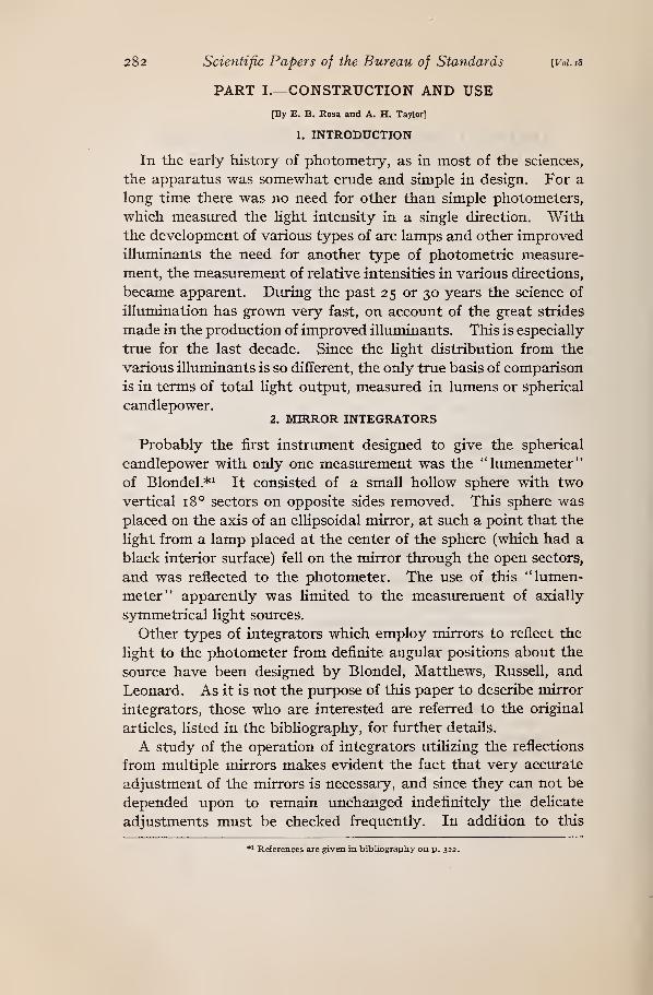
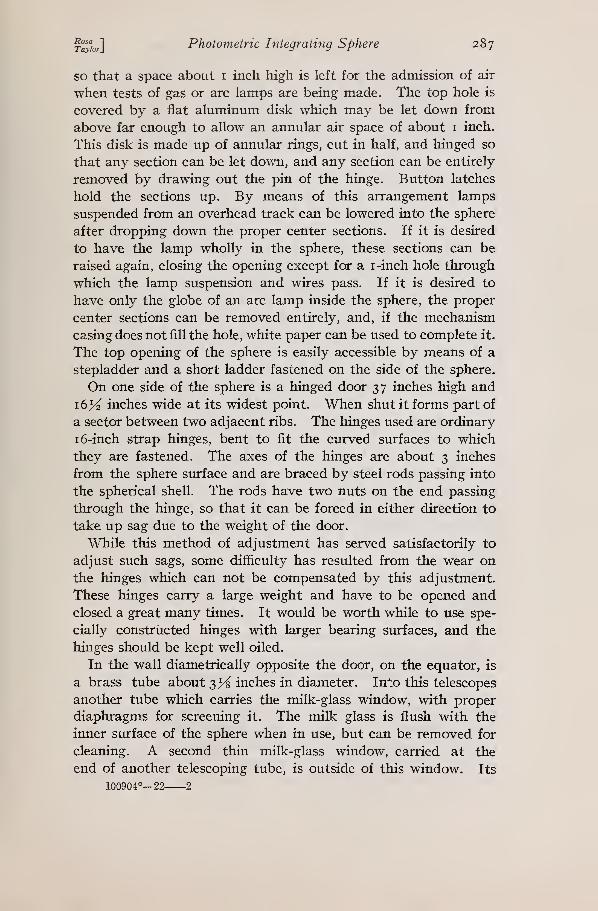
Scientific Papers of the Bureau of Standards, Vol. 18
Fig. I.
—
General view of sphere and auxiliary equipment
j-^'ioJlPhotometric Integrating Sphere 283
disadvantage, accurate integration of axially unsymnietrical light
sources with such integrators is very difficult, if not impossible.
3. ULBRICHT SPHERE
In 1900 Ulbricht^ proposed the use of a hollow sphere, with
diffusely reflecting white walls, for light integration. His results
and the investigations of others have shown that such a sphere,
when properly designed and used, is capable of giving highly
accurate results. Its great simplicity and usefulness have so
strongly recommended it that it has superseded all other types of
apparatus where it is desired to integrate the light flux from
lamps.
Since the Ulbricht sphere has come into such general use, and
is to be found in all well-equipped photometric laboratories of the
present day, it has been thought desirable to give some structural
details of spheres which have been described, as well as the methods
which have been used in constructing a large sphere at the Bureau
of Standards.
4. MATERIALS OF WHICH SPHERES HAVE BEEN CONSTRUCTED
The first sphere with which Ulbricht ^ made his experiments
was a milk-glass ball, 50 cm in diameter, with an opaque cover-
ing. On one side a portion of the wall was unobscured, and the
transmitted light, passing through an opening 8 cm in diameter
in an opaque screen, illuminated the photometer screen.
Blondel was one of the first to realize a practical construction
of the Ulbricht sphere. His sphere was 83 cm in diameter, and
made of sheet metal shaped into hemispheres on a mold.
The smaller sizes of spheres in use to-day are usually made of
sheet metal shaped on molds by pressure or hammering, or of
sectors of sheet metal fastened together by riveting or welding.
The Edison Lamp Works, Harrison, N. J., has an excellent large
sphere of the latter type, in which the sheet-iron sectors are elec-
trically welded. It is divisible into hemispheres. Bloch ^^ de-
scribes a sphere made of zinc plate 2 mm thick, the two halves
of the globe being built up by pressure on a model, and subse-
quently connected by suitable screws and wing nuts. The sizes
larger than i m diameter are usually made of sheet-metal seg-
ments fastened to structural steel or flat steel ribs. Such spheres
have been described by Monasch ^^ and various other writers.
Marchant^^ has described a sphere, at the University of Liver-
pool, 5 feet 3 inches (1.6 m) internal diameter, built of asbestos
284 Scientific Papers of the Bureau of Standards [Voi.is
millboard one-fourth inch (6 mm) thick fastened to 46 five-eighth-
inch T-iron ribs, bent into circular arcs. It is made in halves,
one of which is on rollers. Corsepius " has described a sphere
made of hair plaster, applied to a wire skeleton framework cov-
ered with gauze. Upon this plaster is a coat of plaster of Paris.
A fairly inexpensive spherical integrator can be made up bythe use of a papier-mache globe such as is used in instruction in
geography.
5. OTHER TYPES OF CLOSED INTEGRATORS
Monasch ^^ has advocated the use of a large hemisphere with
flat cover instead of a sphere for certain spherical candlepower
measin-ements, on account of its lower cost and greater ease of
manipulation. He described tests of a hemisphere of 2 m di-
ameter which indicated that the illumination of the photometer
window did not vary greatly when the lamp position was varied,
the differences found being of the order of 2 per cent. This is
too great a variation for precision work, however.
Sumpner ^^ has suggested the use of a rectangular box instead
of a sphere on account of its simpler construction and lower cost.
His article discusses the probable accuracy of such an integrator,
but in the discussion several others disagreed with his conclu-
sions. Details of the construction and use of cubical integrators
have been described by other writers. Anyone interested is re-
ferred to the original literature. (See Bibliography.)
It seems doubtful that a cubical integrator would be very satis-
factory where a higher accuracy than 2 to 4 per cent is desired
for all types of light sources, but it might be quite useful where
certain types of measurements were to be carried out, for ex-
ample, change of efficiency of a gas lamp when the gas rate and
air adjustment are changed. The box could be made to ap-
proach more nearly the spherical shape by blocking up the cor-
ners or filling them with cement. The principal advantage of the
cubical integrator lies in its low cost and simplicity of construc-
tion. A thorough study of such an instrument by a laboratory
equipped to carry out exhaustive tests would perhaps be of con-
siderable value in showing the probable magnitude of the errors
which might be encountered in service. The approach to spheri-
cal shape by blocking up the corners, which should be easy to
accomplish, should be carried out in such an investigation.
Rosa 1Taylor]
Photometric Integrating Sphere
6. BUREAU OF STANDARDS SPHERE
285
During the summer of 191 5 a reinforced concrete sphere, 88
inches (2.23 m) internal diameter, was built at the bureau.
Since many details of its construction are unHke those of spheres
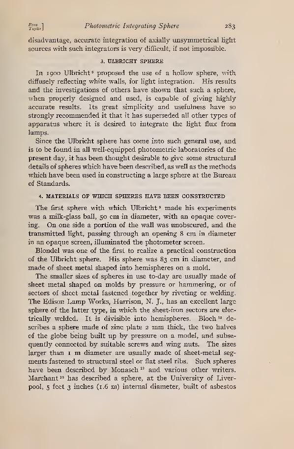
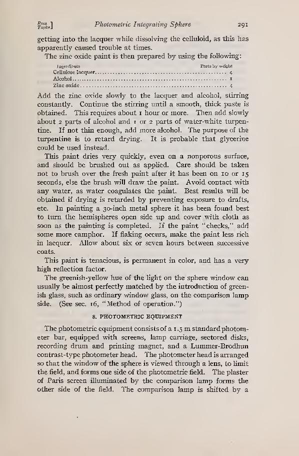
^ A
\ /A-rxlM^STRUCTUF^^HSTEEL Tb-whitIcement{keenes)
,
C-FCRTLANDCEMENT \:siP-EXPANOED mETALLATHE-wms
SWEEP USED INTRUING UP SPHERE.
1
/
Fig. 2.
—
General plan of Bureau of Standards concrete sphere
previously described, it has seemed desirable to give a detailed
description of it. The general plan of the sphere is shown in the
sketches in Figure 2, while Figure i gives a general view of the
sphere and its equipment.
286 Scientific Papers of the Bureau of Standards \voi.is
It has 1 6 vertical ribs of structural steel T, i by i by >^ inch.
(The ribs would be better if three-sixteenths instead of one-
eighth inch thick, as the latter have been found to be too flexible.
Also, the structural framev/ork should be supported above as well
as below while putting on the expanded metal and applying the
cement mortar and plaster, to prevent departure from the true
spherical shape.) The ribs are fastened at top and bottom to
steel rings, made up of 2 by i }A inch angle iron, bent and welded
in rings of 2 feet diameter. Between each pair of ribs are three
steel straps of i by ^ inch section, these being fastened with small
bolts at each end to the top of the T, and butting up against its
web. These strengthen the framework and make it rigid. Be-
tween the ribs are fastened sheets of expanded metal, Such as is
used in ordinary plastering work, cut to fit the spaces and fas-
tened in place by wires passing over the top of the T's, as shown
in the sectional sketch. Figure 2.
The body of the sphere is plastered inside and out with Port-
land cement mortar, of the proportions i part cement to 2K parts
of sand. This was applied to the expanded metal with a curved
trowel, and swept out to a true spherical shape by a suitable
sweep, as shown in Figure 2 . The sweep was made up of a woodencircular arc fastened to an arm. Steel straps were bolted to this
arm, and at the other end they were fastened by a horizontal bolt
at the middle point of a 2-inch pipe which passed through holes in
boards forming bearings at the center of the top and bottom
openings of the sphere. Hence the pipe could turn about a
vertical axis, and the arm about a horizontal axis, thus allowing
the sweep to reach all parts of the spherical surface. The pipe
was threaded at both ends and fitted with lock nuts, so that a
small adjustment up or down could be made. Provision was also
made for a small adjustment of the length of the arm carrying the
sweep. After sweeping, the cement surface was scratched, and
when dry the walls were coated inside and outside with a mixture
of Keene's "fine" cement, with 10 per cent hydrated lime added.
This gives a hard white surface which can be made as smooth as
desired. It is difficult to obtain a pure white surface in this way,
however, if a thin coating is used, as grains of the Portland cement
work up to the surface in applying the white cement. In that
case it is necessary to paint the surface later.
The bottom hole of the sphere is covered by a concave metal
disk standing on three legs on the floor. This disk may be raised
^°'yig^]Photometric Integrating Sphere 287
so that a space about i inch high is left for the admission of air
when tests of gas or arc lamps are being made. The top hole is
covered by a flat aluminum disk which may be let down from
above far enough to allow an annular air space of about i inch.
This disk is made up of annular rings, cut in half, and hinged so
that any section can be let down, and any section can be entirely
removed by drawing out the pin of the hinge. Button latches
hold the sections up. By means of this arrangement lamps
suspended from an overhead track can be lowered into the sphere
after dropping down the proper center sections. If it is desired
to have the lamp wholly in the sphere, these sections can be
raised again, closing the opening except for a i-inch hole through
which the lamp suspension and wires pass. If it is desired to
have only the globe of an arc lamp inside the sphere, the proper
center sections can be removed entirely, and, if the mechanism
casing does not fill the hole, white paper can be used to complete it.
The top opening of the sphere is easily accessible by means of a
stepladder and a short ladder fastened on the side of the sphere.
On one side of the sphere is a hinged door 37 inches high and
i6>^ inches wide at its widest point. When shut it forms part of
a sector between two adjacent ribs. The hinges used are ordinary
16-inch strap hinges, bent to fit the curved surfaces to which
they are fastened. The axes of the hinges are about 3 inches
from the sphere surface and are braced by steel rods passing into
the spherical shell. The rods have two nuts on the end passing
through the hinge, so that it can be forced in either direction to
take up sag due to the weight of the door.
While this method of adjustment has served satisfactorily to
adjust such sags, some difficulty has resulted from the wear on
the hinges which can not be compensated by this adjustment.
These hinges carry a large weight and have to be opened andclosed a great many times. It would be worth while to use spe-
cially constructed hinges with larger bearing surfaces, and the
hinges should be kept well oiled.
In the wall diametrically opposite the door, on the equator, is
a brass tube about 3^^ inches in diameter. Into this telescopes
another tube which carries the milk-glass window, with proper
diaphragms for screening it. The milk glass is flush with the
inner surface of the sphere when in use, but can be removed for
cleaning. A second thin milk-glass window, carried at the
end of another telescoping tube, is outside of this window. Its
100904°—22 2
288 Scientific Papers of the Bureau of Standards [Voi.is
use enables the operator to vary the intensity of the observation
window through a limited range without a material change in
the color of the light. It is much smaller than the other window,
being only a little larger than the field of view of the photometer.
It has been found to be very useful in practical operation of the
sphere.
At a point about 27 inches in front of the window are two
vertical rods upon which a runner may be moved up or down bya string passing through a small tube in the wall directly above.
Four screens of diameters 11, 21, 30, and 38 cm are provided
to be attached to the runner, one at a time, so that for any lampthe smallest screen usable can be chosen.
The method of introducing the lamp socket into the sphere is
unlike any heretofore described. At a point to the left of the
door, just above the equator, a section of one-half-inch conduit
passes into the sphere horizontally to a distance of 13^^ inches,
at which point another section about 23 inches long is hinged to
it. At the end of this section are two lamp sockets, one above
the other, so that lamps can be burned either tip up or tip down.
Voltage and current leads are attached to the sockets in parallel,
passing through the conduit and around the hinge. A short curved
rod is attached to the stationary section just behind the hinge, and
a spring is attached to this rod and to the movable section. Oneend of a flexible cord is fastened to the door and the other end to
the conduit near the lamp sockets. When the door is opened the
sockets are drawn forward to the opening by the cord to facilitate
the change of lamps, and upon closing the door they are drawn
by the spring to a point about 10 inches from the center of the
sphere.
The sphere is supported by a low oak platform. Before apply-
ing the cement all ribs were fastened to the table by long screws,
so that sphere and table are rigidly connected.
7. SPHERE PAINT
One of the most important details of an integrating sphere is
the use of the proper diffusely reflecting white paint. The use of
the zinc white paint recommended by Utzinger ^^ had been con-
templated, but it was not possible to find a colorless glue called
for in the formula. A number of samples of so-called " flat white"
paints were inspected, but none of them proved to be pui^e white
initially, and it is a known characteristic of oil paints that they
gradually become yellow with age. Hence it was finally decided
^"f,")^] Photometric Integrating Sphere 289
that the Keene's cement used in siorfacing the sphere was the
whitest substance available at that time. Two thin brush coats
were applied, allowed to dry, and then sandpapered. Even this
coating is somewhat selective in absorption, though probably less
so than many other coatings in use at present.
The requirements for a satisfactory paint for integrating spheres
are unusually severe. To be entirely satisfactory it should fulfill
the following conditions
:
1. It should be a perfect diffuser, reflecting light in accordance
with the cosine law.
2. It should be tenacious and somewhat elastic.
3. The paint should be a pure white—that is, its reflection
should be nonselective—and it must not change in color with
age or temperature.
4. The reflection factor should be high.
Of these requirements numbers i and 3 are hardest to fulfill.
No oil paint is colorless, and such paints will change in color
with age. Although a perfect diffuser is unobtainable, it is
possible to make up a paint which will fulfill this condition closely
enough for all practical purposes.
When this paint problem arose, extensive experiments were
made in the effort to find or develop a suitable paint. It ap-
peared that the most serious defect of all the commercial paints
exaroined was their color. In order to approximately reproduce
the distortion of color which results from multiple reflections in
the sphere, a test box was made up. It was cubical, with a
colorless ground-glass window in one side, and contained a small
lamp. The reflecting walls were composed of removable card-
boards painted with the paint to be tested. In making a test
the walls were first lined with -black velvet, and the lamp arranged
to illuminate the window directly. This window illuminated the
screen of a I/Ummer-Brodhun photometer. The comparison lampvoltage was then varied until a color match was obtained. Nextthe black velvet was replaced with the test cards, the direct light
was screened from the window, and an effort was made to again
obtain a color match.
After a number of samples of commercial "flat white" paints
had been tested in this manner, without satisfactory results, aneffort was made to develop a suitable paint. D. MacFarlan Moore(discussion ^^) had stated that he had found a zinc-oxide paint,
using a cellulose lacquer for a binder, to be entirely satisfactory.
290 Scientific Papers of the Bureau of Standards {VoUi8
His paint uses amyl acetate, which is expensive and also ob-
noxious because of the toxic effect of the vapor. In an endeavor
to avoid the use of amyl acetate a lacquer was made up by dis-
solving celluloid and camphor in alcohol. Numerous pigments
were tried, the most of the experiments being with magnesium
carbonate and oxide, zinc oxide, and barium sulphate. None of
these were found to be nonselective, all except the barium sulphate
resulting in a greenish-yellow hue which could not be color-
matched very closely by a change of voltage of the comparison
lamp. It was found that the barium sulphate gave the best
results in this respect, and, although it was selective in its ab-
sorption, an almost perfect color match was obtainable by reducing
the voltage of the comparison lamp. Other difficulties were
encountered in trying to make up a paint with this pigment andlacquer and variable results were obtained, so that the effort wasfinally abandoned.
It was found that a fairly satisfactory paint could be made upwith magnesium oxide, but the mixed paint, before being applied,
gradually turns yellow, a perceptible change taking place within
24 to 48 hours. There is apparently no change in color after it is
applied, however.
Although the zinc oxide paint is somewhat selective in its
absorption, it is apparently satisfactory in all other respects, andis now being used in the spheres at the bureau. Before applying
it to the concrete sphere the surface was given a priming coat of
a thin solution of cabinetmakers' glue. Water glass wouldprobably serve equally well, though this has not been tried.
In preparing the zinc oxide paint, first prepare a lacquer com-posed of the following:
Ingredients Parts by weight
Denatured alcohol 100
Camphor 15
Celluloid (colorless, small pieces) 10
Dissolve the camphor in the alcohol before adding the celluloid,
using a motor-operated stirrer. Add the small pieces of clear,
colorless celluloid slowly, while stirring, to prevent them from
sticking together or to the walls of the vessel. Continue the
stirring (covering the vessel) until all the celluloid is dissolved,
which usually requires about 10 or 12 hours. This makes a very
thick, viscous lacquer. Keep a record of the weights used, so
that the alcohol lost by evaporation can be replaced when the
celluloid is dissolved. Use care to prevent any zinc oxide from
^°^^] Photometric Integrating Sphere 291
getting into the lacquer while dissolving the celluloid, as this has
apparently caused trouble at times.
The zinc oxide paint is then prepared by using the following:
Ingredients Parts by weight
Cellulose lacquer 4
Alcohol I
Zinc oxide 4
Add the zinc oxide slowly to the lacquer and alcohol, stirring
constantly. Continue the stirring until a smooth, thick paste is
obtained. This requires about i hoxu- or more. Then add slowly
about 2 parts of alcohol and i or 2 parts of water-white turpen-
tine. If not thin enough, add more alcohol. The purpose of the
turpentine is to retard drying. It is probable that glycerine
could be used instead.
This paint dries very quickly, even on a nonporous surface,
and should be brushed out as applied. Care should be taken
not to brush over the fresh paint after it has been on 10 or 15
seconds, else the brush will draw the paint. Avoid contact with
any water, as water coagulates the paint. Best results will be
obtained if drying is retarded by preventing exposure to drafts,
etc. In painting a 30-inch metal sphere it has been found best
to turn the hemispheres open side up and cover with cloth as
soon as the painting is completed. If the paint "checks," add
some more camphor. If flaking occinrs, make the paint less rich
in lacquer. Allow about six or seven hours between successive
coats.
This paint is tenacious, is permanent in color, and has a very
high reflection factor.
The greenish-yellow hue of the light on the sphere window can
usually be almost perfectly matched by the introduction of green-
ish glass, such as ordinary window glass, on the comparison lampside. (See sec. 16, "Method of operation.")
8. PHOTOMETRIC EQUIPMENT
The photometric equipment consists of a i .5 m standard photom-
eter bar, equipped with screens, lamp carriage, sectored disks,
recording drum and printing magnet, and a Lummer-Brodhuncontrast-type photometer head. The photometer head is arranged
so that the window of the sphere is viewed through a lens, to Hmit
the field, and forms one side of the photometric field. The plaster
of Paris screen illuminated by the comparison lamp forms the
other side of the field. The comparison lamp is shifted by a
292 Scientific Papers of the Bureau of Standards Woi. is
flexible stranded wire belt and pulley arrangement which is
operated by a wheel near the photometer head. The position of
the comparison lamp for a photometric balance is recorded on a
sheet of paper on the recording drum under the lamp carriage byclosing an electrical circuit by a push button in the center
of the handwheel. This apparatus has been previously described
in a publication of this bureau, *^ but it may be of interest to give
a description here. The long cylindrical drum is rotated by anelectrical escapement clockwork, adapted to turn the drum 0.1°
each time the circuit is closed. The axis of the drum is attached
to the axis of the clockwork by a friction clutch, which can be
released so that the drum can be rotated at will. A printing
electromagnet is rigidly attached to the comparison lamp carriage
and moves over the drum lengthwise. This magnet is provided
with two revolving spools carrying a typewriter ribbon between
the printing point and the sheet on the cylinder. The clockwork
and printing magnet are operated in series by a low-voltage battery
(10 to 16 volts), the magnet stamping a dot when the circuit is
closed, the clock turning the cylinder a small amount when the
key opens. The record dots are thus prevented from falling
together. In working up observations the average position of
each bunch of dots is estimated and marked by a straight line,
the position of which is determined by reference to an index line
marked on the paper. The drum is tvuned a small amount be-
tween observations on different lamps.
A Brooks type deflection potentiometer is used for the electrical
measurements.
9. COSTS OF CONSTRUCTION
There have been such large changes in costs of all materials
since the construction of this sphere that it seems to be hardly
possible to estimate present day costs. The materials used would
not be a very large item of cost, but labor would be. It is imcer-
tain whether this type of construction would be less expensive
than all-metal construction for the smaller spheres, but for spheres
larger than 5 feet in diameter it would very probably be less than
for the all-metal sphere.
10. ADVANTAGES OF BUREAU SPHERE
Since this sphere differs in many ways from others in present
use, it will be of interest to point out its advantages and disad-
vantages. Most of the large spheres are diwsible into halves, one
'§Py%^] Photometric Integrating Sphere 293
of which is on rollers, so that they can be separated for adjustment
of arc lamps, etc., in the sphere, and for cleaning and painting.
While this sphere is not divisible, it has been found that one can
very quickly moimt the ladder and make lamp adjustments from
above, in fact, probably more quickly than could be done if one
hemisphere had to be rolled back. This method of construction
also avoids the necessity for a track, which takes up valuable
floor space. In order to permit work on the inner surface of the
sphere, the bottom section can be lifted out. By means of a
stepladder the operator can step into the sphere, and, standing
on the floor beneath the bottom opening, he can easily reach any
part of the spherical surface.
The sphere is rigid and substantial in construction, has a good
surface, continuous (except for necessary openings) and truly
spherical, easily repaired or renewed if necessary, and may be
ventilated if desired. It is not portable, however.
In operation the sphere has been found to possess distinct
advantages due to the use of two sockets for burning lamps either
tip up or tip down, and the arrangement for drawing the lamps
near to the sphere center, good ventilation when desired, and the
use of a standard photometer bar and its accessories.
After having been in use for seven years the surface has shownno signs of cracking or other imperfections.
11. TESTS OF BUREAU SPHERE
The principal tests of this sphere have been made to determine
the accuracy of integration of sources of different types. For this
purpose candlepower distribution measurements of various soiu'ces
were made on a two-mirror selector, and calculated values of meanspherical candlepower were obtained. Direct measurements of the
candlepower of each of the sources were then made in the sphere.
The differences between the results obtained by these two methodsare shown in the last column of Table i , in which positive values
indicate that the results in the sphere were higher than those
obtained by distribution measurements, and negative values indi-
cate that the sphere results were lower. The distribution curves
for these sources are shown in Figure 3.
294 Scientific Papers of the Bureau of Standards [Voi. is
Fig. 3.
—
Light-distribution curves of reflectors used in tests of sphere
TABLE 1.—Comparison of Integration by Distribution Photometer and Integrating
The agreement of the values obtained in the two ways is good,
except perhaps for reflector No. 4. The distribution photometer
measurements are difficult, on account of the low intensity of the
light at many angles (photometer distance was about 10 feet) and
the error is probably greater in those measurements than in the
spherical photometer. No value shown in the table is the result
of many measurements, hence the differences are very probably
due partly to experimental errors.
12. ABSORPTION OF REFLECTED LIGHT BY FOREIGN OBJECTS
In order to measure the absorption of diffusely reflected light byblack objects of various shapes and sizes, a number of these were
made up and painted with lampblack in shellac. Lamp No. i wasburned tip down in reflector No. i, and the test object was sus-
pended near the center of the sphere, where no direct light could
fall on it. The test object was also screened from the sphere
window. The results are shown in Table 2. Where the test
object is designated as "double disk," a disk blackened on both
sides was used, and where the term "single disk" is used, a circu-
lar disk blackened on one side, and fastened to the sphere screen,
on the side away from the window, is indicated. The absorption
values shown in the table indicate the amount by which the
sphere window illumination was reduced when the objects were
suspended in the sphere. The reduction to be expected is shown
by equation (18), to be ^
—
— Hence, if this equation is cor-aA
rect, the values in the last column of the table should all be equal,
since 5 is presumably the only variable in the equation. Thedifferences found, with the exception of the last two, are probably
errors of measurement, since the calculation is a severe test of the
accuracy of the measurements. For example, if the observed ab-
sorption by the cylinder were 0.5 per cent higher, the value in the
last column would be 1 1 .4instead of 10.7. The lower values for the
two globes were probably due to their having cut off some light
from the opaque screen used to screen the window, thereby re-
ducing the total amount of flux received and absorbed by them.
Apparently the absorption is independent of the shape of the ob-
jects, as was to be expected.
100904°—22 3
296 Scientific Papers of the Bureau of Standards [Voi.is
TABLE 2.—^Absorption of Reflected Light by Black Objects of Various Shapes andSizes
Ratio of
percent-age
Object Area -P^^"^fr^" ton?o'
percent-age of
spherearea
Single disk..
Double disk
Cube
Cylinder
Globe No. 1.
Globe No. 2.
AreaSpherearea
Absorp-tion
Cm 2 Per cent Per cent
1152 0.738 7.89
1078 .690 7.65
1110 .711 8.20
1122 .719 7.69
2012 1.288 12.9
3007 1.925 18.4
10.7
11.1
11.5
10.7
10.0
9.6
Tests to determine the amount of absorbtion of reflected light
by clear lamps of sizes from 50-watt carbon to 250-watt vacuumtungsten indicated that the absorption was negligible, being less
than the uncertainty of measurement except in the case of large
lamps with skirted bases.
13. REFLECTION FACTOR OF SPHERE COATING
The reflection factor of the sphere coating was determined in
two ways, one determination being carried out on a separate
sample of the material and one on the complete sphere. For the
latter test the milk-glass window was removed from the sphere
wall, placed on the photometer bar, and a portable photometer
pointed at it. A standard lamp was arranged at a measured dis-
tance from the milk glass, and the photometer standardized to
meastire the illumination on the glass. The window was then
replaced, and the illumination on the window measured when the
same standard lamp was burned in place in the sphere.
Three measin-ements of illumination were made, namely, with
window screened, window unscreened but screen remaining in the
sphere, and screen removed from sphere. The difference between
the first two measurements was the amount of direct illumination
thrown on the window by the lamp alone, and this was subtracted
from the illumination value obtained when the screen was removed
from the sphere. The calculation of the absorption by the sphere
walls is then as follows (for the development of this theory see
Part II)
:
x°yl„] Photometric Integrating Sphere 297
het
E = average total illumination on sphere wall;
Ed = average direct illumination = -r^-ri—^
;
Ejn = illumination by reflected light
;
= measured illumination = E — Ed;
m= reflection factor;
c= absorption factor.
XT '-^d _ '^ ._ T7 _L FT •
Ed + Ejji
Calculations of the observed data on the Keene's cement surface,
using this formula, gave an absorption value of 8.1 per cent, or
reflection factor of 91.9 per cent.
These measiuements indicated a very high reflection factor,
much higher than had been believed to be possible, as a previous
investigator had given 88 per cent as the reflection factor of
magnesium carbonate.*^ Repetition of the measiurements checked
this result, and consequently steps were taken to verify it byanother method. In this method the surface brightness of a flat
disk of the cement was measured at every 10° when illuminated
normally to a known value. These measurements gave further
confirmation of this result. Later another coat of the Keene's
cement was applied and the absorption factor was then found
to be 7.5 per cent, a distinct improvement over the previous
coating.
A measurement of the absorption by the method suggested byChaney (discussion ^^), namely, directing a narrow beam of light
first at the screened area opposite the test plate, and, second, en-
tirely within the unscreened area, gave a result in very close agree-
ment with the above value.
This sphere has recently been painted with the zinc-oxide paint
described above, and the absorption factor remeasured. It wasfound to be 6.0 per cent when the stnface was fresh. This value
was fiurther verified by measm-ement by another method.
As an outgrowth of this work one of the authors has given
special attention to the improvement of methods for the measure-
ment of reflection factors, and has devised two types of reflec-
tometers *"' " in which the principles of the integrating sphere are
appHed. Results with these new instruments have corroborated
the high values of reflection factor mentioned above.
298 Scientific Papers of the Bureau of Standards
14. EFFECT OF LAMP POSITION
[Vol. 18
The change of sphere window illumination when a clear lamp
without reflector was placed in various positions was measured,
and the results are sho^AOi in Figure 4. The lamp used was a
vacuum tungsten lamp. Two methods of varying the position
were used, namely, first, by setting the lamp-socket arm at various
distances from the door, and, second, by suspending the lamp
from a cord at various distances from the door, in each case the
direct light being screened from the observation window by an
opaque screen 38 cm in diameter. The results were practically
the same when a small lamp was tested by the suspension method.
This apparently indicated that the change in window illumina-
"O 1^0 4-0 60 80 100Ciaranc<z of Lamp from i^all oppoaii-e. Wmdoi^ — cm
IZ.0
Fig. 4.
—
Effect of position of lamp on illumination of sphere window
Data for multiple vacuum tungsten lamp. The ordinates are percentages of the illumi-
nation which the same lamp would produce in the empty sphere by reflected light only
tion was not due to absorption of light by the lamp. When the
small lamp was moved toward either of the side walls 90° from
the window, being so arranged that no direct light reached the
observation window, but without employing any large opaque
screen, the window illumination did not decrease as the lampapproached the wall, but, on the contrary, increased slightly.
These and other tests definitely show that the observed decrease
of window illumination as the lamp approached the screened wall
was due to the fact that more and more of the direct light fell on
the screened areas and had to be reflected at least twice before
reaching the window.
From the known values of the light distribution of a lamp of
this type and the absorption of the sphere wall it is possible to
calculate the decrease to be expected. Such values have been
calculated for two sizes of screen, of 38 and 19 cm diameter, respec-
^°^^^] Photometric Integrating Sphere 299
tively, and plotted as solid curves in Figure 4. For the 38 cmscreen the observed curve has arbitrarily been given the same
value as the calculated curve for the position nearest the center of
the sphere. The close agreement between calculated and observed
curves confirms the reason advanced above for the observed
change. In neitlier case is the reduction of total illumination due
to absorption of multiple reflected Hght by the opaque screen
taken into accotmt, but it is not necessary to do so, since it is
practically independent of the light distribution or position of the
lamp. The method by which the calculated curve was obtained
will be explained in the second part of this paper.
If a light source of extended area, such as a dififusing globe, is
brought near the screened sphere wall, a decrease greater than
that shown by Figure 4 will be observed, for in addition to the
greater flux on the screened area there will be the additional
effect of greater absorption by the globe itself, since it receives a
greater fraction of the first reflected flux than when it is nearer
the center of the sphere.
Probably the greatest error which occurs in the use of inte-
grating spheres is caused by placing the lamps too near the sphere
wall and making no correction for light absorbed by them. Whentesting life-test lamps in this manner, where the lamp may be
appreciably blackened and consequently absorbs more reflected
light than it did when new, the error is undoubtedly too large to
be neglected.
15. SELECTIVE ABSORPTION BY THE SPHERE SURFACE
In the bureau sphere, as is probably the case everywhere, there
is som.e selective absorption by the sphere wall coating. Since
this is such a general condition, it is desirable to know whether
or not it causes any error, and if so, approximately how much.
A test to determine the amount of selectivity, or, in other words,
the difference between the color of the light given out by a lampand the color of the light emerging at the window, was madewhen the surface was coated with Keene's cement. For this
prurpose the sphere window w^as removed and placed on one side
of the photometer. When a vacuum lamp of an efficiency of
about 1.2 watts per horizontal candle illuminated the v/indov/
directly, the comparison lamp gave the nearest color match at
98 volts, with an efficiency of 1.33 watts per horizontal candle.
(This difference is due to selective absorption by the milk-glass
window.) The first lamp was then placed in the sphere, burned
300 Scientific Papers of the Bureau of Standards [Voi. is
at the same voltage, and the voltage of the comparison lamp
altered imtil the best color match was again obtained. Its voltage
was then 70, and its efficiency approximately 2.75 watts per hori-
zontal candle. A perfect color match is not obtainable in either
case, partly because of selective absorption by the milk-glass
window. Although this characteristic of milk glass probably does
not cause any appreciable error of measurement, it does make the
photometric observations somewhat more difficult.
In order to determine whether or not any error of measure-
ment results from selective absorption by the sphere walls, the
amount of which has already been described, the following ex-
periment was performed:
Two lamps of the same type were selected. One of these wasused as the comparison lamp, and the other was put in the sphere.
The voltages were set to give about the same efficiency, that is,
about I.I wphc, and a reading taken. The voltages of both
lamps were then altered until an efficiency of about 3.15 wphcwas obtained, and another reading taken. Since there is a large
color difference encoimtered in reading the photometer when the
lamp is in the sphere, evidently about equal for both conditions,
precautions were taken to keep outside of the range of the Pur-
kinje effect by making the illumination of the photometer screen
practically equal in both cases.
The lamp was then removed from the sphere and arranged to
illuminate the milk-glass window, which had been set up on the
bar photometer. The measurements at the two efficiencies were
then repeated.
If there is no error due to the selective absorption, the ratio of
the illumination of the sphere window at the two voltages with
one lamp in the sphere should be the same as that obtained whenthe lamp was measured on the bar photometer. If there is any
error, it would be expected that the lamp in the sphere would be
underrated at the higher efficiency on account of the greater ab-
sorption of the whiter Hght.
The ratios of the illumination in the two cases differed by only
0.4 per cent, which was within the error of measurement, since
the measurements in the sphere were difficult because of the
color difference. It is to be noted, also, that the difference was
in the direction opposite to that to be expected if there was any
error introduced by the selectivity. Hence it seems safe to con-
clude that over this range of color difference no measurable error
RosaTaylor]
Photometric Integrating Sphere 301
due to selective absorption applied to measurements made in
this particular sphere.
At present it is very difiicult to obtain for the window a dif-
fusing material which does not have some selective absorption.
Milk glass usually has a higher absorption in the blue end of the
spectrum, while clear glass in great thicknesses is usually green.
Experimental work at the bureau has shown that good milk
glass loses practically nothing in diffusion properties by being
grotmd down to a thickness of less than i mm, while a very ap-
preciable gain will be made in reduced selective absorption and
increased transmission. The surface toward the sphere should
be given the coarsest possible grinding with coarse carbonmdumor by sandblasting.
16. METHOD OF OPERATION
The "substitution" method which is used in practically all the
photometric work in the bvueau makes possible the adjustment of
the apparatus to the best condition of measurement in every case.
This method also obviates any necessity for long-continued con-
stancy of many factors in the measurements, such as the candle-
power of the comparison lamp, the reflection factor of the shpere
walls, etc.
The illumination on either side of the photometer screen is
varied in part by the use of a set of sectored disks, depending on
the well-known law that if the illumination of any smiace is
obstructed by means of a rapidly rotating sectored disk, the
apparent brightness of the surface is directly proportional to the
angular opening of the disk. In certain cases neutral absorption
glass screens are used, though usually this is done only where the
factor for the glass need not be known.
When the color of the light from the test lamps is very different
from that from the standard lamps, it is desirable to use some
method of altering the color of incident light from the comparison
lamp in order to facilitate the measmrements and free them from
this element of uncertainty. The method used here is the inter-
position in the path of the Hght of glass cells filled with colored
liquids. These are made up by trial, and in cases where it is
necessary to know the relative transmissions, this standardization
is made by means of a flicker photometer. The solutions used are
water solutions of potassium bichromate and of copper sulphate.
The desired color can be approximated by varying the densities of
the solutions or by mixing them. In the use of such cells, if the
302 Scientific Papers o^ the Bureau of Standards ivoi.is
relative transmissions must be known, the measurements should
be made with a lamp of the same color as the comparison lamp
to be used. Also, it is undesirable to use the cells to alter the
light from the sphere, for this light varies in color according to
the color of the lamps tested, and the transmission of a solution
is known to be appreciably different for lights widely different in
color.
Another method which has proved very successful is the use of
ordinary window glass which has a greenish hue. When used of
the proper thickness, on the comparison lamp side, it is usually
possible to obtain a nearly perfect color match with the paint
described above, and in some other cases. When used in this
manner a correction should be made for the change in length of
the optical path. Insertion of the glass has the effect of shorten-
ing the optical path, so that it is less than the measured distance
by an amount approximately equal to one-third of the thickness
of the glass.
To facilitate the work of evaluating the readings an inverse
square scale, with divisions expressing percentages, was ruled on
a transparent triangle. By setting an index line on the triangle
to coincide with an index line on the sheet on which the photo-
meter readings have been printed by the electromagnet, the pro-
portionalities of the various readings can be read off. By the aid
of a slide rule these are easily convertible into candlepower values.
In the case where lamps not widely different in candlepower are
to be measured, a candlepower scale can be prepared. The varia-
tion of the intensity of the comparison lamp throughout a small
voltage range where it is to be used should be experimentally de-
termined, so that small adjustments can be made by varying its
intensity. The method of measurement most easily carried out
would then be somewhat as follows
:
Put a standard lamp in the sphere, and set the comparison
lamp at the point on the scale to make it read directly the spher-
ical candlepower of the standard lamp, first having determined
the voltage of the comparison lamp for a color match with the
standard. Next alter the position of the secondary sphere
window (if a double window such as that described above is used)
until an intensity match is obtained. Take readings on several
standard lamps, and if it is found that they read high or low
by a small amount, change the voltage of the comparison lamp
by the predetermined small amount necessary to make the read-
^°f.°^^] Photometric Integrating Sphere 303
ings correct. Readings on one or more standard lamps should be
made at frequent inten^^als throughout the run, to check the
accuracy of tlie measurements. Vv^'here high precision is desired,
a number of standard lamps should be read both at the beginning
and the end of the observations, and if the results in the two cases
do not agree, an adjustment of the values must be made or the
nm discarded if the disagreement exceeds a permissible amount.
The above method applies to the use of a sphere with which a
bar photometer is used. With such a photometer bar a regular
Lummer-Brodhim sight box can be used, one side of the sight
box being removed so that the sphere window forms one side of
the photometric field.
It is possible also to use a portable photometer, such as the
Sharp-Millar, which has an inverse square scale, but it is evident
that the use of such an instrument will not give an acciu-acy as
high as that obtainable with a bar photometer and accessories.
In meastirements of light sources having surfaces which absorb
an appreciable amount of light, the following procedure, which is
the general practice, is probably best:
The opaque screens to be used are placed in position, and a
reading of the standard lamp, without the test lamp in the sphere,
is taken. Next, a small shield is arranged to screen from the test
lamp when in position any direct light from the standard lamp,
and another reading is taken. The test lamp is then brought into
the sphere, in the position which it is to occupy, but unlighted,
and another reading is taken. The percentage difference between
the readings in the last two cases is the reduction of sphere win-
dow illumination due to the absorption of reflected light by the
test lamp. When the readings of the test lamp are evaluated in
terms of the reading of the standard lamp in the empty sphere
this percentage should be added to the results. This is a very
important correction, as appreciable errors may occur if it is not
taken into account. A modified procedure consists in taking
readings on the standard lam-p vfhen the test lamp is in the sphere,
and evaluating the results on the test lamp directly in terms of
the readings on the standard lamp. In this method, as before,
precautions should be taken to screen from the test lamp the
direct light from the standard lamp. The former method has anadvantage if many lamps of the same kind are to be measured,
or if the same lamp is to be measured many times, since in that
case a constant percentage correction can be applied to the cbser-
304 Scientific Papers of the Bureau of Standards [Voi.is
vations evaluated in terms of observations on standard lamps in
the empty sphere.
It is good practice to cover large absorbing surfaces, such as arc
lamp mechanism casings, with white paper or cardboard, whenever
it can be done in such a manner as not to cut off any light emitted
by the lamp.
17. SPECIAL USES OF INTEGRATING SPHERES
In addition to the measiu-ement of mean spherical candle-
powers the sphere may be used to make other important measiu-e-
ments. Its use for hemispherical candlepower measurements has
been extensively discussed in some of the articles listed in the
bibliography. It can also be used for the measm-ement of the
effective light flux within a given solid angle. (See discussion
of reference,^* by Chillas.) For these measurements a sphere
divisible into hemispheres is more useful. The use of the hemis-
pheres for measiu'ements on searchlight beams has been described
.
by Benford.38 39
The integrating sphere principle has recently been applied to the
measurement of diffuse reflection factors by one of the present
authors/"** Its use for this purpose promises to fill a long felt
want.
The testing of jewels for the Panama-Pacific International
Exposition is an interesting application of the sphere which has
been described by S. L. E. Rose (discussion ^'). Many other
applications of the apparatus will doubtless be made in future.
18. CONCLUSION
It may be said in conclusion that the authors believe that in the
hands of careful and experienced photometricians a properly
designed sphere will give very accurate results, and forms one of
the most important parts of the equipment of a photometric
laboratory.
Since the present types of lamps vary greatly in their light dis-
tribution, and change differently in distribution as they are
burned (as, for example, in a life test) , the only true basis of com-parison is in terms of their spherical intensity or total flux, andthis is rapidly becoming the accepted practice.
The sphere described above has proved very satisfactory in
practice, and is in more nearly constant use than any other ap-
paratus in the photometric laboratory.
The authors are indebted to E. C. Crittenden for many helpful
suggestions and for the selection of the photometric equipment.
^ay%r] Photometric Integrating Sphere 305
PART II.—THEORY[By A. H. Taylor]
1. INTRODUCTION
The theory of the Ulbricht sphere has been extensively treated
in the literature listed in the accompanying bibliography, but a
great deal of the discussion is a repetition of certain phases of the
general theory, and in no one place is there a complete discussion
of all details of the theory. Hence it has been thought desirable
to give here a fairly complete resume of the theory, together with
new developments of certain phases, with especial regard to the
best design of the sphere to increase the accuracy of measurement.
In preparing this paper the works of Ulbricht," ' ** and Chaney
and Clark '^ have been freely consulted, as they have given
the most complete discussions of the theory available until very
recently, but a large part of the applied theory given here is
new. In a number of other parts new methods of development
which are believed to be less complex than those previously used
have been followed.
2. GENERAL THEORY
Theoretical photometry makes use of two general laws of
radiation; first, that the intensity of illumination of a surface is
inversely proportional to the square of its distance from the light
source, and, second, the cosine law of emission, often erroneously
referred to as I^ambert's cosine law,*^ which states in substance
that the luminous intensity of an element of a perfectly diffusing
luminous stirface is directly proportional to the cosine of the angle
between the normal to the surface and the line of emission. Fromthe latter law it follows that the brightness of such a siu"face is
independent of the angle of view and that the luminous intensity
is directly proportional to the projected area. No luminous
surface obeys this law exactly, but it is possible to produce a
surface which will approach fulfillment of the law. For simplicity
in the following theoretical treatment exact fulfillment of the law
is assumed, tmless otherwise stated. The effect of deviations
from exact fulfillment is discussed later in this paper.
In considering the general theory of the sphere certain relations
between brightness and the luminous flux emitted or received will
be found very useful. The proofs can be found in another Scien-
tific Paper of this bureau,^' or they can be derived very simply
3o6 Scientific Papers of the Bureau of Standards Woi.'s
by the methods of the integral calculus. These relations are as
follows
:
Unit area of a plane disk radiating luminous flux in accordance
with the cosine law of emission—that is, one which has the samebrightness h (candles per unit of projected area) at all angles of
view—radiates a total flux of tt 6 lumens *
A unit plane illuminated by a parallel infinite plane of uniform
brightness h receives x h lumens.
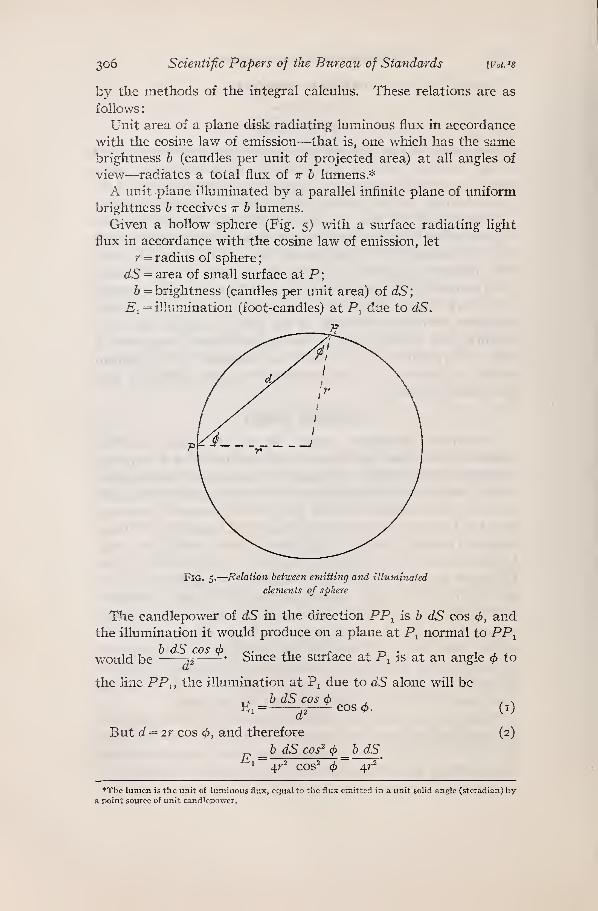
Given a hollow sphere (Fig. 5) with a surface radiating light
flux in accordance with the cosine law of emission, let
r = radius of sphere
;
dS = area of small surface at P;
& = brightness (candles per unit area) of dS;
E^ = illumination (foot-candles) at P^ due to dS.
J?
Fig. 5.
—
Relation between emitting and illuminated
elements of sphere
The candlepower of dS in the direction PP^ is b dS cos 4>, andthe illumination it would produce on a plane at P^ normal to PP^^
would be J2 Since the surface at Pi is at an angle ^ to
the line PP., the illumination at Pj due to dS alone will be
-rA b dS cos 4> J / NEi= j^COS0. (i)
But d = 2r cos 4>, and therefore (2)
b dS cos^ (f> b dS^x = 4r^ cos^ cf) 4.r
*The lumen is the unit of luminous flux, equal to the flux emitted in a unit solid angle (steradian) bya point source of unit candlepower.
RosaTaylor.]
Photometric Integrating Sphere 307
Since P^ may be any point on the interior surface of the sphere,
it is evident that any element of surface illuminates all other ele-
ments of the svirface equally. Hence, in a sphere having a
surface which reflects light in accordance with the cosine law, the
illumination of the surface by reflected light only is equal at all
points, regardless of any asymmetry of the light received directly
from the soitrce or of any variation of the reflection factor of
the surface from point to point.
£d = the average illumination (foot-candles) of the sphere
surface by hght received directly from the lamp
;
Em = the illumination by diffusely reflected light ojily;
E = the average total illumination;
m = reflection factor of the sphere surface
;
a = absorption factor of the sphere surface.
= I — m;F = total light flux (lumens) radiated by lamp in sphere
;
A = area of sphere surface.
Em is composed of light of which a portion has been reflected a
great many times, and hence Em = mEd +m^Ed + etc.
E = Ed+Em, or
E = Ea (i -\-m-\-m^ -{- -fm(°-*') =Ed. (3)I —
m
Since n is infinite,
£ =^^=^- (4)I — m a
This result can be obtained by other methods also, one of which
is as follows
:
Since the hollow sphere is a closed surface, all of the light flux
radiated by the lamp will be absorbed. The intensity of the total
illumination will depend on the absorption factor of the surface.
An analogy to this is the strength of the current in a resonant
electrical circuit.
HenceE E E
aEA =E^, E = —T=—> smc&-r = Ed. (5)aA a A ^-^^
3. ERRORS OF MEASUREMENT DUE TO SCREEN
The illumination of any particular point may differ from E,
since the direct illumination Ed varies with the light distribution
of the source and its distance from the point considered. In order
to measure Em, which is directly proportional to /, the spherical
* Since an illumination of one foot-candle is produced by one lumen incident per square foot.
3o8 Scientific Papers of the Bureau of Standards [Voi.is
candlepower of the lamp, it is necessary to insert in the sphere
wall a diffusely transmitting window and to screen from it the
direct light from the lamp in the sphere. Relative values of the
brightness of the window are then proportional to the relative
spherical intensities of the lamps tested. However, the neces-
sary use of the screen to cut off the direct light from the window,
and the insertion of the lamp into the sphere alter the above
theoretical value of Em somewhat on account of obstruction and
absorption of light by them, and it is important to know the mag-
nitude of the possible error which may occur.
In a sphere in which the direct light is screened from the obser-
vation window the direct light may be considered as having two
components as regards its effect on the brightness of the observa-
tion window, namely, the part A, which is incident on the sur-
faces visible from the observation window, and the part B, which
falls on the areas screened from the window. The part A can
illuminate the window by the first reflection, but the part B must
suffer one extra reflection before any of it can reach the window.
Any constant difference between the theoretical and observed val-
ues of Erci will be compensated for by the substitution method of
photometry, but variable differences, due to different fractions of
the total direct flux of the two lamps being incident on the screen
and screened area, will cause errors of measurement.
Let 6 = fraction of total light flux F incident on screen and
screened area.
The portion of direct light reflected from the zone unscreened
from the observation window (zone 3, Fig. 6) is mF(i — S). Its
effect on the observation window is the equivalent of a secondary
source radiating that amount of light flux in an empty sphere.
Hence the illumination of the observation window due to it is
mF(i — 5)
^ The portion dF suffers two reflections before any of it
reaches the observation window, and its effect on the window is
the equivalent of a source radiating m^6F lumens. Hence the
total illumination of the window is
„, JTmFii -8) m^dF~\^ =\ aA ^^AT]
(6)
tmFTC= ^^[(i -8 +md)] = K'(i -8a),
where i^ is a proper fraction introduced to make allowance for
the absorption of reflected light by the lamp and opaque screen.
Rosa I
Taylor!Photometric Integrating Sphere 309
The factor K is practically constant if the screen is small, but
6 is variable, being dependent on the distribution of light from
the source. Its value may be anything between o and i, being
o if no direct light is incident on these areas. Hence the maximumpossible error is a, the absorption factor of the sphere surface.
If the substitution method of photometry is used, the error of
measurement e would be given by the equation
{h'-b")a
wherei-b'a
8' = value of 5 for standard lamp;8" = value of 5 for test lamp.
(7)
Fig. 6.
—
Screened and unscreened zones of sphere with
light source at center
Zone I is screened from the source, and the observing
window is placed in it. Zone 2 is therefore screened from the
window. Zone 3 is not screened from either source or
window.
4. POSITION AND SIZE OF SCREEN
As has been indicated above, errors are caused by the screen
only when different fractions of the direct flux of the two sources
being compared fall on the screen and screened area. Assumingthat the screen has the same reflection factor as the sphere sur-
face, its effect on the light which falls directly upon it is prac-
tically the same as if an equivalent zone (zone i. Fig. 6) were
screened from the observation window. In general, it is evident
that the smaller this equivalent zone and the zone actually
screened from the window (zone 2, Fig. 6) are made, the less
chance there will be of errors resulting.
3IO Scientific Papers of the Bureau of Standards [Voi.j8
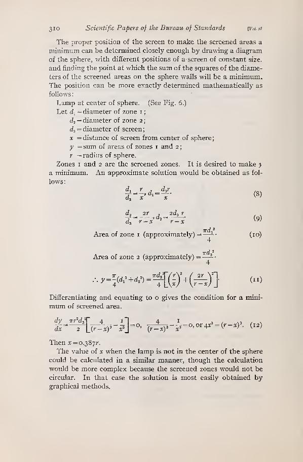
The proper position of the screen to make the screened areas a
minimum can be determined closely enough by drawing a diagram
of the sphere, with different positions of a screen of constant size,
and finding the point at which the sum of the squares of the diame-
ters of the screened areas on the sphere walls will be a minimum.The position can be more exactly determined mathematically as
follows
:
Lamp at center of sphere. (See Fig. 6.)
Let di = diameter of zone i
;
J2 = diameter of zone 2
;
(ig = diameter of screen
;
X = distance of screen from center of sphere
;
y = sum of areas of zones i and 2
;
r = radius of sphere.
Zones I and 2 are the screened zones. It is desired to make y
a minimum. An approximate solution would be obtained as fol-
lows:
2r , 2(^3 r-, at = (o)
1-2 -" 7 ^1*3
"3 r — X
wd ^
Area of zone i (approximately) =
—
-- (10)
Area of zone 2 (approximately) =—- •
4
Differentiating and equating to o gives the condition for a mini-
mum of screened area.
dy Trr^d;
\_(r-xy x?_= 0' (7Z^~^ = °'0^4^ = (^~^)'- (^2)
Then x = o.2)?>'jr.
The value of x when the lamp is not in the center of the sphere
could be calculated in a similar manner, though the calculation
would be more complex because the screened zones would not be
circular. In that case the solution is most easily obtained bygraphical methods.
RosaTaylor,
Photometric Integrating Sphere 311
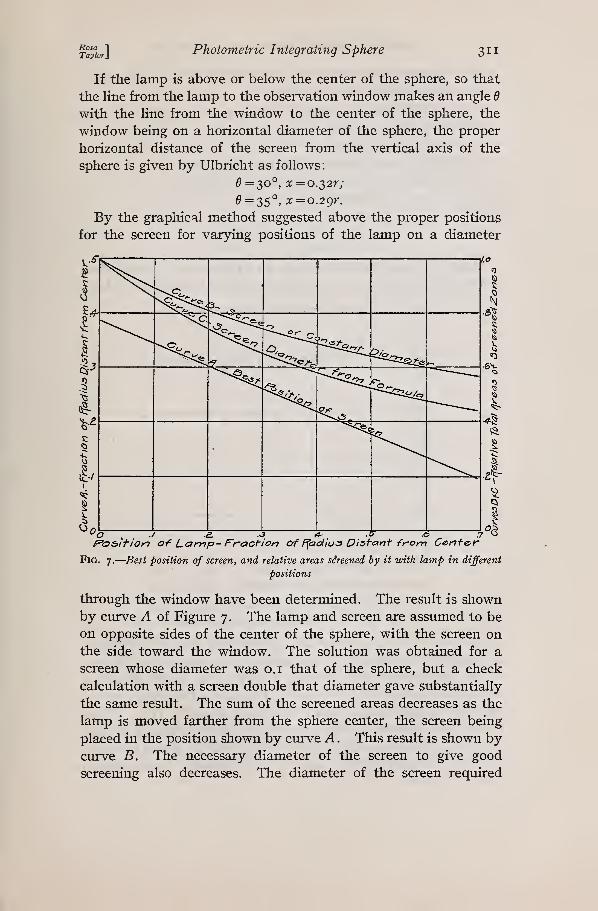
If the lamp is above or below the center of the sphere, so that
the line from the lamp to the observation window makes an angle d
with the line from the window to the center of the sphere, the
window being on a horizontal diameter of the sphere, the proper
horizontal distance of the screen from the vertical axis of the
sphere is given by Ulbricht as follows
:
e=30°,x=o.S2r;
^ = 35°, x = o.2gr.
By the graphical method suggested above the proper positions
for the screen for varying positions of the lamp on a diameter
foSiition of Lamp- Fraction of f^adius Distant fronn Cente,r
Fig. 7,
—
Best position of screen, and relative areas sireened by it with lamp in different
positions
through the window have been determined. The result is shownby curve A of Figure 7. The lamp and screen are assumed to be
on opposite sides of the center of the sphere, with the screen onthe side toward the window. The solution was obtained for a
screen whose diameter was o.i that of the sphere, but a check
calculation with a screen double that diameter gave substantially
the same result. The sum of the screened areas decreases as the
lamp is moved farther from the sphere center, the screen being
placed in the position shown by curve A . This result is shown bycurve B. The necessary diameter of the screen to give good
screening also decreases. The diameter of the screen required
312 Scientific Papers of the Bureau of Standards YVol. i8
when the screen and lamp are on opposite sides of the sphere
center may be determined as follows:
Let / = the greatest dimension of lamp to be screened, or length
of locus of light som-ce;
r = radius of sphere
;
ar = distance of lamp from center of sphere
;
br = distance of screen from center of sphere
;
d! = required diameter of screen.
Then
(13)d (j-b) r i-b/ (i + a) r I + a
Hence it is seen that the diameter of the screen is independent
of the size of the sphere, and depends only on the positions of lamp
X /
1--4 .
—
/^ /
/§.
4 >/1
^
a. y1 _^^ •
D 40' eo' IZ.O' 160 2.00"
Anajic ofCone ^t»e /U19 li Normal fo^lj 0^ Filam&nta
Fig. 8.
—
Percentage of totalfluxfrom vacuum tungsten lamp
included in cones of various apertures normal to lamp axis
and screen and the length of the largest lamp which it is desired
to measiu-e (assuming that one screen is to serve for all lamps.
If the lamps vary much in size, it may be desirable to have a
series of interchangeable screens). For safety the screen should
be made slightly larger than the solution given by (13). Curve
C in Figure 7 shows the relative total areas of the screened zones
for various positions of lamp and screen, when the screen diameter
is chosen by equation (13) and the screen is located according to
curve A, Figtire 7.
Rosa "1
Taylor} Photometric Integrating Sphere 313
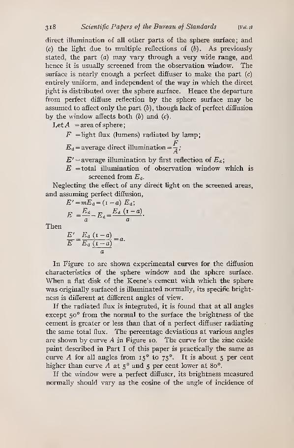
In Figxire 8 is shown, for the common type of vacuum tungsten
lamp, the percentage of the total light which is emitted in cones of
various angles with their axes normal to the axis of the filaments.
The angle of the beam incident on each screened area is easily
obtained, and by reference to this curve the percentage of the total
flux which is incident on the screened area may be found. If
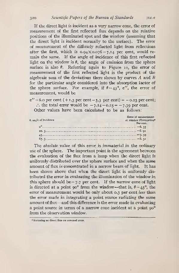
when the lamp is in the center of the sphere the diameter of the
proper screen is 0.2 or 0.4 of the sphere radius, its proper diameter
for other positions of the lamp is shown by the solid curves of
Figiure 9, and the percentage of the total flux of a vacuum tungsten
o y ^ :3 14- :s :s 7? r&fion <^ Lamp -Frac'I'iO'n oi" Ffadiu^ Dijiant from Cenivf of Jphere^
Fig. 9.
—
Diameter of screens and percentage of light flux falling on parts screened fromobserving window with lamp in different positions
It is assumed that the lamp is such as to require a screen diameter either (i) 0.4 or (2) 0.2 of the sphere
radius when the lamp is at the center of the sphere. Diameters for other positions are then calculated from
equation 13, and positions are determined by curve A, Fig. 7. The flux calculations apply to vacuumtmigsten lamps (see Fig. 8). The percentage of flux indicated falls on the screen and on the zone screened
from the window, but both of these may be considered as zones of the sphere wall (see Fig. 6)
lamp which is incident on the zones screened from the window is
shown by the broken curves in the same figtue.
This type of lamp gives more nearly than any other commontype of incandescent lamp the light distribution which would be
obtained from a straight luminous rod, and it is improbable that
any other type of filament arrangement except the motion picture
projection lamp would give a larger percentage of its total flux
in any solid angle normal to the lamp axis not exceeding 90°.
Hence, if the best locations of lamp and screen for measurements
of lamps of this type are chosen, they would probably be approxi-
mately the best for measurements of lamps of other types also.
From the curves in Figure 9 it is seen that the flirx on the screened
zones is a minimmn for this type of lamp when the lamp is removed
314 Scientific Papers of the Bureau of Standards [Voi.is
0.2 of the radius from the center of the sphere, though there is
very little choice between this position and any other between
the center and 0.4 r. Since the total screened area is less at the
0.4 r position, that position would probably be preferable, at least
in spheres larger than about i yard or i m in diameter. Other
considerations may make desirable a position nearer the center in
the smaller spheres, but this must be judged largely by the use to
which the sphere is to be put. If the lamp is placed too near the
wall, there will be another factor to be reckoned with, namely,
absorption of first reflected light by the lamp. The effect of this
will be brought out more clearly in the following paragraphs.
5. ABSORPTION OF LIGHT BY FOREIGN OBJECTS
If any foreign object is brought into the sphere, it will absorb
light and reduce the illumination of the sphere window, even
though it is screened from the window.
As before, let
Ejr, = illumination by reflected Hght (foot-candles)
;
Ea = average direct illumination
;
a = absorption factor of sphere sirrface
;
a' = absorption factor of foreign body in sphere;
F = total light flux from source, in lumens
;
r = radius of sphere, in feet;
6 = average brightness of sphere wall (candles per square
foot) when there is no foreign body in the sphere
;
h' = average brightness of sphere wall when the foreign body
is in the sphere
;
5 = surface area of foreign body
;
A = area of sphere.
As previously stated, the illumination at any point in front of
an infinite plane of brightness h is Tth. Also, the flux given off byunit area is irh lumens.
If the foreign body is far enough from the walls of the sphere so
that it does not reduce the illumination of the walls unequally,
and does not receive any direct Hght from the lamp, it will receive
the average illumination -wh' foot candles (since the illuminating
surface is equivalent to an infinite plane), and altogether the
flux irh'S, of which it will absorb the fraction irh'Sa' lumens.
The surface of the sphere radiates the Hght flux irb'A lumens
and absorbs the fraction a of the total flux received. Hence it
WA, , ,
irh'A,
receives and absorbs a lumens.I —a I—
a
§111^] Photometric Integrating Sphere 315
Since all the light is absorbed, the flux absorbed must equal the
total flux radiated by the lamp, or
, ,irab'A
irb'Sa -\ =F- (14)I — a ^ ^
.;_ F(i-a)TrSa'{i-a)+TraA ^^^^
If there is no foreign body in the sphere, then
must equal F, andI —a ^
F (i-g)6= -7 (16)ira A ^
HenceF(i-a)
b' rSa' (i — a) +TaA a Ab F(i-a) Sa'{i-a)+aA'
ira A
(17)
or
6':6 = i:i4-4^-^. (18)
If the foreign body is brought near the surface of the sphere
(the foreign body is assumed to be something other than the lamp
in this case) , it cuts off some light from the wall approached, and
hence its absorption of reflected Hght is less because the brightness
of the wall approached is reduced. If the foreign body is the light
source itself, the absorption is increased, because the lamp receives
a greater fraction of the first reflected light. The value in (18) is
nearest correct when a and 5 are small, since in that case the
brightness of the sphere wall is most nearly uniform.The results shown in Table 2, page 296, apparently indicate
that the absorption of reflected light by foreign objects is inde-
pendent of their shape, which is to be expected from the theory
as developed above.
6. EFFECT OF LAMP POSITION
In Figure 4, page 298, are given calculated and observed curves
showing the reduction of sphere window illumination as the lampapproaches the portion of the wall screened from the observation
window. The calculated curves were obtained in the following
manner:
31
6
Scientific Papers of the Bureau of Standards [Voi.is
A diagram of the sphere similar to Figure 6 was drawn, and the
outline of the screened area, zone 2, was established. By the aid
of a protractor the angles at the lamp subtended by the screen
and zone 2 were measured, and from the curve in Figure 8 the
percentages of the total flux which are incident on the screen and
zone 2 were obtained. For example, take the case when the 38
cm screen is used and the lamp is 76 cm (30 inches) from the
door. Then the angles at the lamp which are subtended by the
screen and zone 2 are 27° and 88°, respectively. Referring to
Figure 8, the flux incident on the screened areas is found to be
18. 1 per cent of the total delivered by the lamp. Since = 7.5
per cent, the illumination of the observation window is shown byequation (6) to be
E'=K' {i-ba)=K' (1-0.18iX0.075) =0.986 i^',
which is 99.7 per cent of the illumination of the window when the
lamp is 99 cm from the door, or 98.6 per cent of the theoretica
value for the illumination of the empty sphere by reflected light
only.
If a source giving all its light on the unscreened area is meas-
ured in terms of vacuum tungsten standards in this sphere, using
the substitution method, the error of measurement to be expected
would be given by the curves in Figure 4. For example, if the
lamp and reflector were 100 cm from the sphere door, the error
would be plus 0.2 per cent with a 19 cm screen, and +1.0 per cent
with a 38 cm screen. If this were the only factor affecting the
accirracy of the results, it would be expected that higher values
in terms of such standards would be obtained for an opaque re-
flector unit as it approached the screened wall, since practically
all of the direct Hght falls on the unscreened area. As a matter
of fact, however, meastirements of such a unit, evaluated in terms
of a standard lamp measured in the same positions, gave constant
results at all positions up to about 20 cm from the sphere wall;
that is, the sphere window illumination fell off in about the same
proportion with the reflector unit as with the bare lamp. Theprobable reason for this was that the reflector unit absorbed more
and more Hght as it approached the wall because it received moreof the first reflected light from the wall, and the reduction due to
this cause happened to be just the same in amount as was to be
expected in the case of the bare lamp, where the reduction was
due to absorption by the screened areas. It should be noted here
T°ayioT'\Photometric Integrating Sphere 317
that a screen of about 19 cm diameter is large enough for the
measurement of all sizes of incandescent lamps in this sphere, andthat the 38 cm screen would be used only in case a lamp of very
extensive area was to be measured. Since nearly all other types
of incandescent lamps and reflector units throw a still smaller
proportion of their total flux on the screened areas in this sphere,
the error of meastirement due to the screened areas should not
exceed 0.3 per cent when a 19 cm screen and vacuum tungsten
standards are used, the lamp being in its normal position, 25 cmfrom the sphere center, and it would be as great as this only whenmeasuring a source which threw all its light on the unscreened
areas.
In case a lamp which threw all its light on the screened area
was measured with the 19 cm screen, the lamp being at the 100
cm position, the error would be —(a — 0.3 per cent) = —7.2 per
cent. This is an extreme case, however, since in such a measure-
ment the logical method would be to direct the beam toward the
unscreened area, when the error would be only +0.3 per cent.
This method of analyzing the operation of a sphere makespossible an estimate of the error which may be encountered in
practice with a definite arrangement of sphere screen, lamp
socket, etc., and such an analysis would be valuable in considering
the accuracy of integration with any particular sphere. It should
not be overlooked, however, that differences in absorption of
reflected light by the standard and test lamps may cause errors
greater than these.
7. ERROR OF INTEGRATION OF NARROW CONE OF LIGHT
In the theory of the sphere as developed above, and in all the
literature on the subject, the assumption has been made that
the sphere sturface is a perfect diffuser. Also, it has been assumed
that the translucent window is a perfectly diffuse transmitter of
light, so that the brightness of the observed side is directly pro-
portional to the illumination of the opposite side, regardless of
the angle of incidence of the light contributing to this illumina-
tion. These ideal conditions are not realized in practice, and
hence it is important to determine the amount of the departures
and the error which may occur on account of them.
The illumination of any part of the surface of a sphere surfaced
with rough white cement or a matt white paint may be analyzed
into three components: (a) The light flux received directly from
the lamp; (6) the flux contributed by the first reflection of the
3 1
8
Scientific Papers of the Bureau of Standards [voi. is
direct illumination of all other parts of the sphere surface; and
(c) the light due to multiple reflections of (6). As previously-
stated, the part (a) may vary through a very wide range, and
hence it is usually screened from the observation window. Thesurface is nearly enough a perfect diffuser to make the part (c)
entirely uniform, and independent of the way in which the direct
light is distributed over the sphere surface. Hence the departure
from perfect diffuse reflection by the sphere surface may be
assumed to affect only the part (6) , though lack of perfect diffusion
by the window affects both (6) and (c)
.
LetA = area of sphere
;
F = light flux (lumens) radiated by lamp;
FEa = average direct illumination = -j /
£' = average illumination by first reflection of E^;
E = total illumination of observation window which is
screened from £d-
Neglecting the effect of any direct light on the screened areas,
and assuming perfect diffusion,
E' =mEa = (i —a) E^;
Then
In Figure lo are shown experimental curves for the diffusion
characteristics of the sphere window and the sphere surface.
When a flat disk of the Keene's cement with which the sphere
was originally surfaced is illuminated normally, its specific bright-
ness is different at different angles of view.
If the radiated fltix is integrated, it is found that at all angles
except 50° from the normal to the svirface the brightness of the
cement is greater or less than that of a perfect diffuser radiating
the same total flux. The percentage deviations at various angles
are shown by curve A in Figure 10. The curve for the zinc oxide
paint described in Part I of this paper is practically the same as
cm-\^e A for all angles from 15° to 75°. It is about 5 per cent
higher than curve A at 5° and 5 per cent lower at 80°.
If the window were a perfect diffuser, its brightness meastued
normally should vary as the cosine of the angle of incidence of
E Ea rr Ed (i -
^ a ^'- a
-a)
E'
E^d (i-a)_^Ed (i -a)
Rosa1
Taylor]Photometric Integrating Sphere 319
the light on the opposite side (angles being measured from the
normal). Cmve B shows the deviation of a milk-glass window,
surfaced with coarse carborundum (No. 60), from the cosine law
of transmission.
If a photometer is standardized to measure the normal illumi-
nation on the face of this milk glass opposite to the side viewed,
calculations show that if the window was illuminated by a uni-
formly bright infinite plane the evaluation of the illumination would
flmgl0 fr'onn Norrr}al to 3oi^'fac&
Fig. 10.
—
Diffusion characteristics of Keene's cement and depolished milk-glass
•3a-
be too low by 7.6 per cent. This is practically the condition in the
sphere as regards the portion (c) defined above. If the sphere
surface is illuminated normally to a uniform amount, as would be
the case if a point source of Hght was placed at the center of the
sphere, the illumination due to the first reflected flux, not per-
fectly diffused (see curve A), would be evaluated too low by 8.8
per cent. Hence, since the absorption factor of this sphere is
now 6.0 per cent, and since that also represents the ratio of E' to
E (see above), the error in the measured value of the windowillumination would be
h) Special tests of and with integrating spheres: 8, 9, 10, 12,
13, 15, 21, 23, 29, 31, 35, 36, 37, 38, 39, 40.
11. BIBLIOGRAPHY
1. Blondel, La determination de I'intensite moyenne spherique des sources de
lumiere, L'^clair. Elect., 2, p. 385, 1895; 3, p. 57, 406, 538, 583, 1895; C. R.,
120, p. 311, 550, 1895.
2. Blondel, Mesure directe de I'intensite lumineuse moyenne spherique, L'Eclair.
E;iect., 8, p. 49; 1896.
3. C. P. Matthews, An improved apparatus for arc-light photometry, Trans. A. I. E. E.,
18, p. 671, 1901; 20, p. 59, 1902; L'Eclair. Elect., 40, p. 128, 1904; J. Inst.
Elec. Engr., 32, p. 631, 1903.
4. Blondel, Les integrateurs photometriques, mesophotometres et lumeumetres,
Bull. Societe Internationale des Electricians, 4, p. 659, 1904; L'Eclair. Elect.,
42, p. 66, 1905; Sci. Abst. B, 8, abst. 487 and 1689, 1905.
j-l^^]Photometric Integrating Sphere 323
5. E. P. Hyde, On the theory of the Matthews and the Russell-Leonard photometers
for the measurement of mean spherical and mean hemispherical intensities.
B. S. Bulletin 1, 1905 (or B. S. Sci. Papers, No. 12).
6. G. H. Stickney and S. L. E. Rose, Photometry of large light sources. Trans. I. E. S.,
6, p. 641; 1911.
7. Stmipner, The diffusion of light, Phil. Mag., 35, p. 81; 1893.
8. R. Ulbricht, Die bestimmung der mittleren raumlichen lichtintensitat durch
nur eine messung, ETZ, 21, p. 595, 1900; Sci. Abst., 3, abst. 2154, 1900.
9. Ulbricht, Die vorange im kugelphotometer, ETZ, 26, p. 512, 1905; Sci. Abst.,
8, abst. 1160, 1905.
10. L. Bloch, Das kugelphotometer in theorie und praxis, ETZ, 26, p. 1047, io74.
1905; Illuminating Engineer (New York), 1, p. 421, 1906; Sci. Abst., 8, abst.
1688, 1905.
11. Ulbricht, Die hemispharische lichtintensitat iind das kugelphotometer, ETZ,27, p. 50, 1906; L'Eclair. Elect., 46, p. 432, 1906; Sci. Abst., 9, abst. 370,
1906.
12. M. Corsepius, Eine ausfuhrungsform des Ulbrichtschen kugelphotometers, ETZ,27, p. 468, 1906; Illuminating Engineer (New York), 1, p. 482, 1906; Sci.
Abst., 9, abst. 772, 1906.
13. B. Monasch, Versuche mit hilfsapparaten zur bestimmung der mittleren sphari-
schen und der mittleren hemispharischen lichtstarke, ETZ, 27, p. 669, 695,
803, 1906; Illuminating Engineer (New York), 1, p. 586, 700, 1906; Sci. Abst.,
9, abst. 1233, 1906.
14. E. Presser, Die theorie der Ulbrichtschen kugel, Elektrotechnischer Anzeiger,
p. 885, 912, 1906.
15. Ulbricht, Zur anwendung des kugelphotometers, ETZ, 28, p. 777, 1907; Elec-