***CAUTION: Do not lift by yellow enclosure. Reference installation instructions for proper lifting and moving techniques. THERM-O-MIX ® STATION LP INSTALLATION & TESTING MANUAL LOW PRESSURE UNIT
Transcript
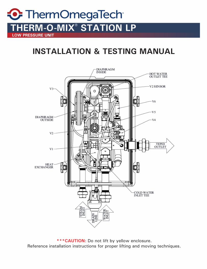
***CAUTION: Do not lift by yellow enclosure.Reference installation instructions for proper lifting and moving techniques.
THERM-O-MIX® STATION LP
INSTALLATION & TESTING MANUAL
LOW PRESSURE UNIT
IMPROPER INSTALLATION MAY RESULT IN RISK OF SCALDING
PRE-INSTALLATION:
Mounting: Always use back-up wrench when connecting to the Therm-O-Mix® unit. Do not allow rotation of any piping while connecting steam and water lines. Rotation of piping in or on station may cause damage and malfunction.
Piping & Connections: Freeze and scald protection valves MUST be installed as per industry standards on the Therm-O-Mix® Station’s inlet water supply line and outlet line to the connected safety fixture.
If heat tracing is applied to the water supply line, the freeze protection valve may be installed as backup protection. Heat tracing on inlet water piping must be regulated to maintain water temperature below 85°F. Depending on system piping layout, additional freeze and over-temperature protection valves may be required.
Compliance: The Therm-O-Mix® Station complies with ANSI Z358.1 and designed to meet ASSE 1071 (American Society of Sanitary Engineers for Temperature Actuated Mixing valves for
Plumbed Emergency Equipment) requirements.
INSTALLATION:
Air Gap: During operation the Therm-O-Mix® Station’s drain line discharges steam condensate, water, and some flash steam vapors. The drain line is equipped with an air gap to prevent obstruction of the drain.
The drain line must be unobstructed and free-flowing for the unit to operate correctly. No steam trap should be used on this line; the addition of a steam trap or restriction may result in a scalding hazard. The drain line must be piped so that there is no back pressure restriction. Do not tie other drain lines into drain pipe.
In applications where air gap is removed - plumb piping directly to the drain line and replace air gap at the end of piping AT MOST 10 feet from the station. Drain line piping must be steeply sloped to ensure proper drainage. If collecting drained water for reuse, do not submerge or block the drain line.
POST INSTALL TESTING:
Testing: ANSI Z358.1 standards mandate testing the Therm-O-Mix® Station’s operation and outlet temperature weekly to validate unit functionality and tepid water availability. Refer to the Testing Checklist (included - page 6) for complete testing instructions.
*** CAUTION ***
INSTALLATION CHECKLIST
THERM-O-MIX® STATION
Remove Therm-O-Mix® from box by having two people lift from underneath the enclosure.***Do not stand unit up, lay fl at until ready to install
STEP 1: REMOVE FROM BOX
Therm-O-Mix® should only be grasped by the inlet and outlet piping while mounting. Consider removing front cover to allow for easy access to hand holds.
STEP 2: HANDLING
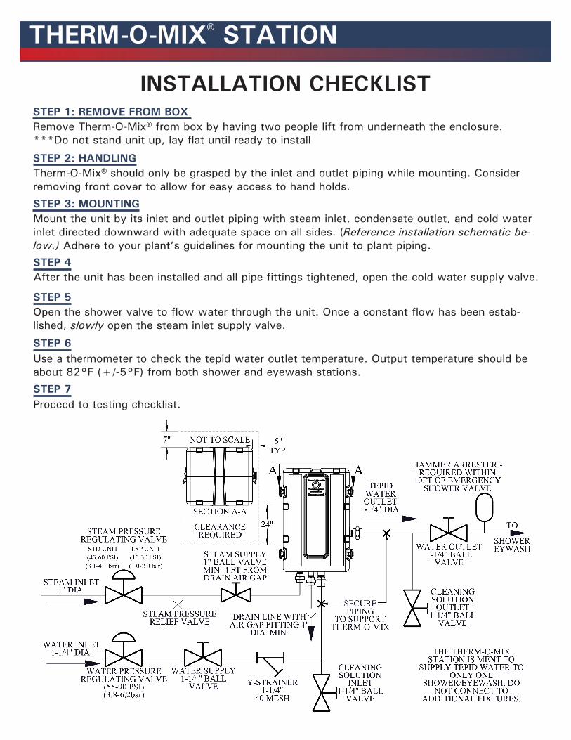
Mount the unit by its inlet and outlet piping with steam inlet, condensate outlet, and cold water inlet directed downward with adequate space on all sides. (Reference installation schematic be-low.) Adhere to your plant’s guidelines for mounting the unit to plant piping.
STEP 3: MOUNTING
After the unit has been installed and all pipe fi ttings tightened, open the cold water supply valve.STEP 4
Open the shower valve to fl ow water through the unit. Once a constant fl ow has been estab-lished, slowly open the steam inlet supply valve.
STEP 5
STEP 6Use a thermometer to check the tepid water outlet temperature. Output temperature should be about 82°F (+/-5°F) from both shower and eyewash stations.STEP 7Proceed to testing checklist.
REMEMBER: CONSULT WITH THERMOMEGATECH®, INC. APPLICATION ENGINEERS FOR ANY QUESTIONS REGARDING INSTALLATION, OPERATION, OR MAINTENANCE.
CAPACITY: The Therm-O-Mix® produces up to 25 GPM (94.6 L/min) of 80ºF (26.7ºC) water for one shower/eyewash combination. At that fl ow, there will be a pressure drop of approximately 25 PSI (1.7 BAR) across the unit. The water heater is designed to activate at a minimum fl ow of no less than 3 GPM (11.4 L/min).
INSTALLATION: The Therm-O-Mix® is designed to supply tepid water for one shower/eyewash combo at a time. This water heating system should be installed in close proximity to the shower (5’ to 12’ of 1 1/4” IPS piping between the Therm-O-Mix® outlet and the shower inlet). It should be clearly identifi ed, with easy access, and should remain free of obstructions. Supply lines must be heat-traced if subject to freezing temperatures. If any part of the piping network runs through a cold area, this piping should be temperature controlled with self-regulating heat tape. Any heat-traced piping should be protected with scald protection bleed valves. Complicated chains of showers and eyewashes, long piping runs, and recirculating loops should all be evaluated by a qualifi ed engineer.
IMPORTANT: The Therm-O-Mix® is designed for intermittent operation only. Outlet tepid water must only be used for emergency shower/eyewash stations. Continuous operation and/or use of tepid water for other applications may result in hazardous conditions and potential personal injury. Improper operation is not covered in warranty.
LIFTING: Caution: Do not lift unit by grasping yellow enclosure. Yellow enclosure is not designed to support weight. When lifting, moving or aligning, always grasp the inlet and outlet piping only. NEVER GRASP THE UNIT BY THE ENCLOSURE.
MOUNTING: Caution: DO NOT MOUNT YELLOW ENCLOSURE DIRECTLY TO THE WALL. Unit weighs 105 lb. (47.6 kg) empty, and is designed to be supported by the cold water inlet and tepid water outlet piping union connections. Proper mounting is required to maintain access for testing and service. Unit must be mounted so that both halves of the yellow enclosure may be removed for service. Minimum recommended clearance of 7”.
*See included Installation drawing. Remove plugs from inlet and outlet unions and save for future use (when servicing the unit). Flush piping prior to connecting to inlet unions to eliminate debris. Connect outlet union to piping leading to shower/eyewash. Check for leaks.
CAUTION: All inlet and outlet piping to the Therm-O-Mix® should remain independent and should not be tied in together at any point.
INSTALLATION INSTRUCTIONS
THERM-O-MIX® STATION
THERM-O-MIX® STATION
STEAM: STEAM INLET PRESSURE MUST BE REGULATED at 15 PSI to 30 PSI for low pressure units.
If a pressure regulator is required it is recommended that a pilot-operated steam pressure regulating valve be used to maintain the pressure setting under all fl ow conditions. If the supply pressure to the regulator is greater than 75 PSI (5.2 BAR), then a pressure relief valve must be used. For operation at other pressures, consult factory.The Therm-O-Mix® contains internal steam trap. Redundant steam traps are not recommended.
MAXIMUM STEAM TEMPERATURE IS 350ºF (176.7ºC).Pipe steam inlet with 1” Schedule 40 (minimum) pipe. Install a 1” ball valve for service isolation and as a safety shutoff.
CAUTION: Always use back-up wrench when connecting to the Therm-O-Mix® unit. Do not allow rotation of any piping on station while connecting steam and water lines. Rotation of piping in or on station may cause damage and malfunction.
DRAIN PIPE: This line should be piped with 1” Schedule 40 (minimum) pipe to steeply sloped air gap within 10’, catch basin or open drain. If operated in freezing temperatures the drain line must be heat traced and terminated 12” from grade to prevent blockage due to freezing.
CAUTION: This line must be free-fl owing in order for the unit to operate correctly. NO STEAM TRAP SHOULD BE USED ON THIS LINE! ADDITION OF STEAM TRAP OR RESTRICTION WILL CAUSE SERIOUS SCALDING HAZARD! During operation of the Therm-O-Mix® unit, this line will discharge condensate and drain water from the system and some fl ash steam vapors. It must be piped so that there is no back pressure restriction. Do not tie other drain lines into drain pipe.
In order to prevent freeze damage to the water supply line to the Therm-O-Mix® or to the safety shower/eyewash station, and to safeguard against over temperature water conditions caused by solar radiation, heat tracing, or other local heat sources, FREEZE AND SCALD PROTECTION VALVES MUST BE INSTALLED per industry standards prior to and after the station. If heat tracing is applied to the water supply line, the freeze protection valve may be installed as backup protection. Depending on system piping layout, additional freeze and over-temperature protection valves may be required.
WATER: MINIMUM WATER INLET PRESSURE OF 55 PSI (3.8 BAR). Water pressure up to 90 PSI (6.21 BAR) is allowable as long as the downstream fl ow rate is regulated to less than 25 GPM (94.6 L/min). Pipe the water inlet using 1 1/4” schedule 40 (minimum) pipe. Where sediment or mineral content is a problem, an in line fi lter and strainer is required. A water hammer arrestor is required to be installed at most 10 FT from the shower valve.
CAUTION: Always use a back-up wrench when tightening union connection to prevent damage.
MAINTENANCE: Consult the factory before attempting any maintenance.
INSTALLATION INSTRUCTIONS CONT.
Remove the Therm-O-Mix® station’s front cover.STEP 1
Check the condensate drain to confi rm it is free of restriction and blockage. Some dripping from condensate drain is normal while the station is idle, but no steam should be seen.
STEP 2
Check blue rubber hoses for signs of leakage and tighten clamps if necessary
STEP 3
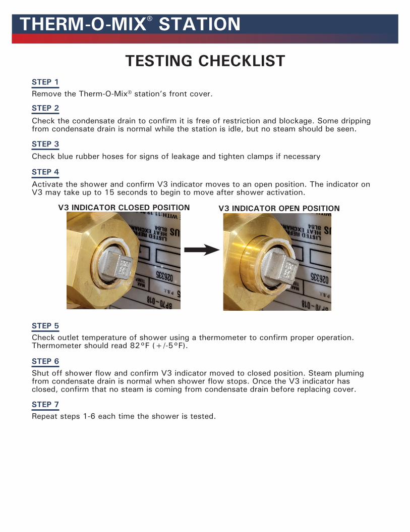
Activate the shower and confi rm V3 indicator moves to an open position. The indicator on V3 may take up to 15 seconds to begin to move after shower activation.
STEP 4
Check outlet temperature of shower using a thermometer to confi rm proper operation. Thermometer should read 82°F (+/-5°F).
STEP 5
Shut off shower fl ow and confi rm V3 indicator moved to closed position. Steam pluming from condensate drain is normal when shower fl ow stops. Once the V3 indicator has closed, confi rm that no steam is coming from condensate drain before replacing cover.
STEP 6
Repeat steps 1-6 each time the shower is tested.STEP 7
V3 INDICATOR CLOSED POSITION V3 INDICATOR OPEN POSITION
TESTING CHECKLIST
THERM-O-MIX® STATION
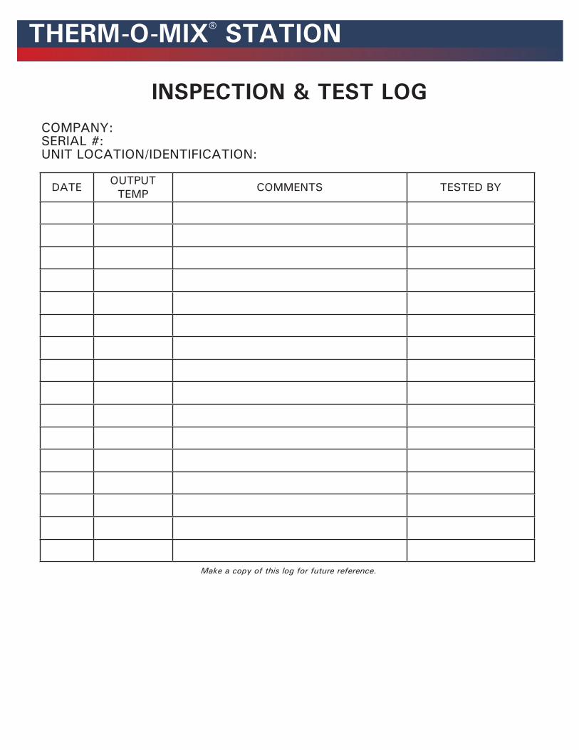
DATE OUTPUTTEMP COMMENTS TESTED BY
Make a copy of this log for future reference.
COMPANY:SERIAL #:UNIT LOCATION/IDENTIFICATION:
INSPECTION & TEST LOG
THERM-O-MIX® STATION
ThermOmegaTech® warrants that this specifi c product is guaranteed against defective material or poor workmanship for a period of two years from date of shipment.
ThermOmegaTech® liability under this warranty shall be discharged by furnishing without charge F.O.B. ThermOmegaTech® Factory any goods, or part thereof, which shall appear to the Company upon inspection to be of defective material or not of fi rst class workmanship, provided that claim is made in writing to ThermOmegaTech® within a reasonable period after receipt of the product.
Where claims for defects are made, the defective part or parts shall be delivered to the Company, prepaid, for inspection. ThermOmegaTech® will not be liable for the cost of repairs, alterations or replacements, or for any expense connected therewith made by the owner or his agents, except upon written authority from ThermOmegaTech®. ThermOmegaTech® will not be liable for any damages caused by defective materials or poor workmanship, except for replacements, as provided above.
Buyer agrees that ThermOmegaTech® has made no other warranties either expressed or implied in addition to those above stated, except that of title with respect to any of the products or equipment sold hereunder and that ThermOmegaTech® shall not be liable for general, special, or consequential damages claimed to arise under the contract of sale.
The emergency equipment manufactured by ThermOmegaTech® is warranted to function if installation and maintenance instructions provided are adhered to. The units also must be used for the purpose for which they were intended. This product is intended to supplement fi rst-aid treatment. Due to widely varying conditions, ThermOmegaTech® cannot guarantee that the use of this emergency equipment will prevent serious injury or the aggravation of existing or prior injuries.
NO OTHER WARRANTIES EXPRESSED OR IMPLIED ARE AUTHORIZED, PROVIDED OR GIVEN BY THERMOMEGATECH®.
SHOULD YOU EXPERIENCE DIFFICULTY WITH THE INSTALLATION OF THIS PRODUCT PLEASE CONTACT MANUFACTURER.
LIMITED WARRANTY
THERM-O-MIX® STATION
WARNING: This product can expose you to chemicals, for example lead, nickel, acrylonitrile, which are known to the State of CA to cause cancer, birth defects, or reproductive harm. For more information, go to www.P65Warnings.ca.gov
ThermOmegaTech®, Inc.353 Ivyland Road 1-877-379-8258Warminster, PA 18974 www.ThermOmegaTech.com