PATIO DOOR SYSTEMS ® Therma-Tru Hinged Patio Door System Double/Triple Panel Unit Assembly Read all instructions before starting. The applicable standards for these products are governed by the International Residential Code. Copies of performance ratings and testing are available on our website www.thermatru.com and our product manual.
Transcript
PATIO DOOR SYSTEMS
®Therma-TruHinged PatioDoor System
Double/Triple PanelUnit Assembly
Read all instructions before starting.
The applicable standards for these products are governed bythe International Residential Code.
Copies of performance ratings and testing are available on our website www.thermatru.com and our product manual.
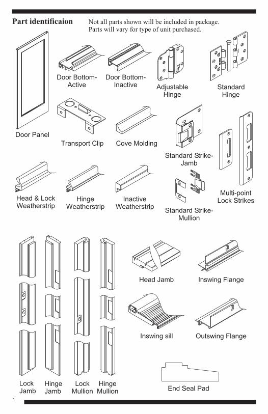
Part identificaion
Inswing sill
Door Bottom-Active
Door Bottom-Inactive Standard
HingeAdjustable
Hinge
Head Jamb
LockJamb
HingeJamb
LockMullion
HingeMullion
Head & LockWeatherstrip
Door Panel
HingeWeatherstrip
InactiveWeatherstrip
Standard Strike-Mullion
Inswing Flange
Outswing Flange
Not all parts shown will be included in package.Parts will vary for type of unit purchased.
Transport Clip Cove Molding
End Seal Pad
Standard Strike-Jamb
Multi-pointLock Strikes
1
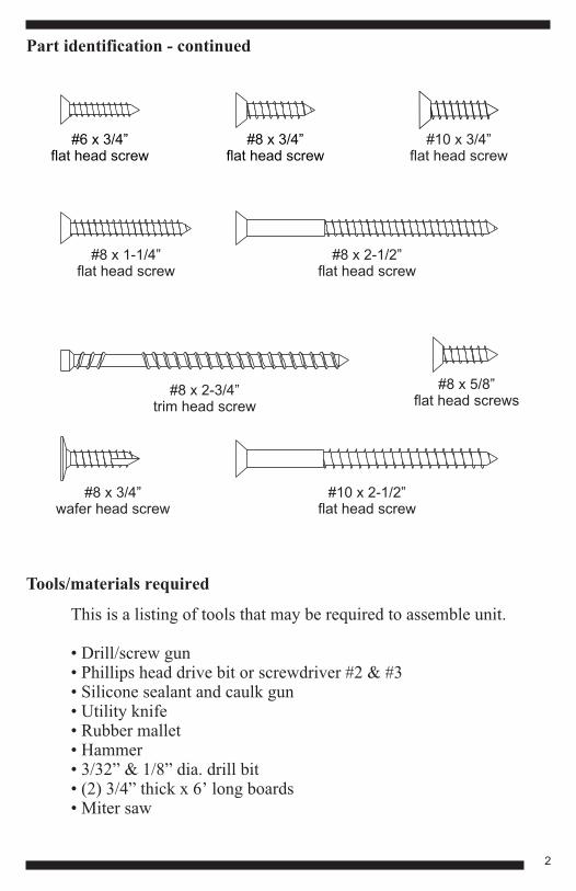
Part identification - continued
Tools/materials required
#10 x 3/4”flat head screw
#8 x 1-1/4”flat head screw
#8 x 3/4”wafer head screw
#10 x 2-1/2”flat head screw
#8 x 2-1/2”flat head screw
#8 x 2-3/4”trim head screw
#6 x 3/4”flat head screw
#8 x 3/4”flat head screw
This is a listing of tools that may be required to assemble unit.
• Drill/screw gun• Phillips head drive bit or screwdriver #2 & #3• Silicone sealant and caulk gun• Utility knife• Rubber mallet• Hammer• 3/32” & 1/8” dia. drill bit• (2) 3/4” thick x 6’ long boards• Miter saw
#8 x 5/8”flat head screws
2
1
2
REMOVE COMPONENTS FROM PACKAGING
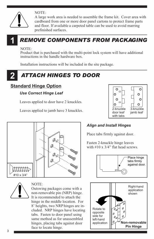
ATTACH HINGES TO DOOR
NOTE:Product that is purchased with the multi-point lock system will have additional instructions in the handle hardware box.
Installation instructions will be included in the site package.
NOTE:A large work area is needed to assemble the frame kit. Cover area with cardboard from one or more door panel cartons to protect frame parts and floor. If available
.a carpeted table can be used to avoid marring
prefinished surfaces
2-knuckledoor leafwith tabs
3-knucklejamb leaf
Use Correct Hinge Leaf
Leaves applied to door have 2 knuckles.
Leaves applied to jamb have 3 knuckles.
Standard Hinge Option
Align and Install Hinges
Place tabs firmly against door.
Fasten 2-knuckle hinge leaves with #10 x 3/4” flat head screws.
Place hingetabs firmlyagainst door.
Rotate tooppositeside forleft-handapplication
Right-handapplicationshown
Non-removablePin Hinge
NOTE:Outswing packages come with a non-removable pin (NRP) hinge.It is recommended to attach the hinge in the middle location. For 8’ heights, two NRP hinges are in-cluded. NRP hinges have locating tabs. Fasten to door panel using same method as for unassembled hinges, placing tabs against door face to locate hinge.
#10 x 3/4”
3
2
3
ATTACH HINGES TO DOOR - continued
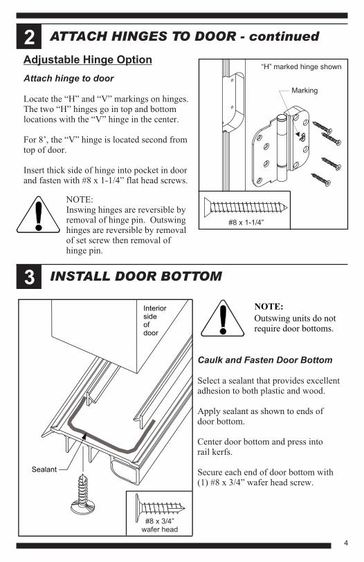
INSTALL DOOR BOTTOM
Adjustable Hinge Option
#8 x 1-1/4”
Attach hinge to door
Locate the “H” and “V” markings on hinges.The two “H” hinges go in top and bottomlocations with the “V” hinge in the center.
For 8’, the “V” hinge is located second fromtop of door.
Insert thick side of hinge into pocket in door and fasten with #8 x 1-1/4” flat head screws.
Sealant
Interiorsideofdoor
NOTE:
Outswing units do notrequire door bottoms.
Caulk and Fasten Door Bottom
Select a sealant that provides excellentadhesion to both plastic and wood.
Apply sealant as shown to ends ofdoor bottom.
Center door bottom and press intorail kerfs.
Secure each end of door bottom with (1) #8 x 3/4” wafer head screw.
#8 x 3/4”wafer head
NOTE:Inswing hinges are reversible byremoval of hinge pin. Outswinghinges are reversible by removalof set screw then removal ofhinge pin.
“H” marked hinge shown
Marking
4
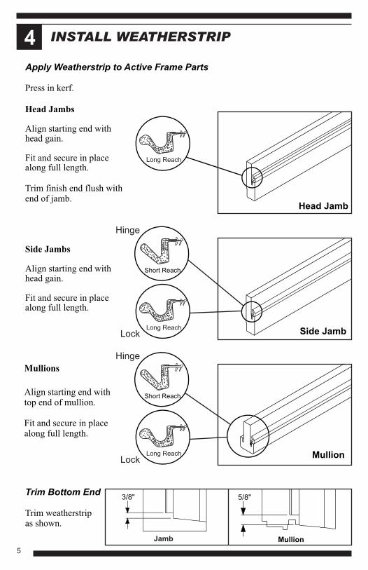
INSTALL WEATHERSTRIP4
Apply Weatherstrip to Active Frame Parts
Press in kerf.
Trim Bottom End
Trim weatherstripas shown.
Side Jambs
Head Jambs
Align starting end with
Align starting end with
head gain.
head gain.
Fit and secure in place
Fit and secure in place
along full length.
along full length.
Trim finish end flush withend of jamb.
3/8"
Jamb
Mullions
Align starting end withtop end of mullion.
Fit and secure in placealong full length.
Short Reach
Short Reach
Long Reach
Long Reach
Long ReachSide Jamb
Head Jamb
Mullion
Hinge
Hinge
Lock
Lock
5/8"
Mullion
5
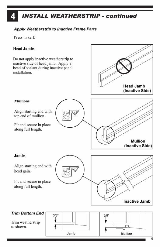
4 INSTALL WEATHERSTRIP - continued
Apply Weatherstrip to Inactive Frame Parts
Trim Bottom End
Trim weatherstripas shown.
3/8"
Jamb
5/8"
Mullion
Jambs
Mullions
Align starting end with
Align starting end withtop end of mullion.
Fit and secure in placealong full length.
head gain.
Fit and secure in place
along full length.
Press in kerf.
Head Jambs
Do not apply inactive weatherstrip toinactive side of head jamb. Apply abead of sealant during inactive panelinstallation.
Mullion(Inactive Side)
Inactive Jamb
Head Jamb(Inactive Side)
6
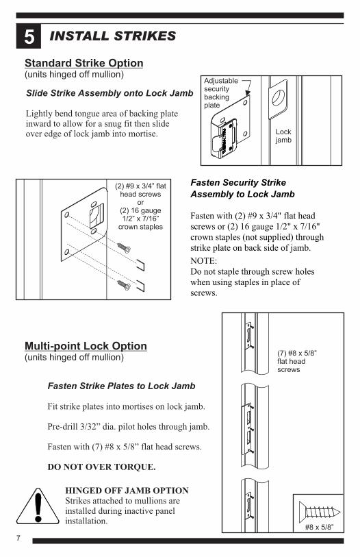
INSTALL STRIKES5
Fasten Security Strike
Assembly to Lock Jamb
Fasten with (2) #9 x 3/4" flat head
screws or (2) 16 gauge 1/2" x 7/16"
crown staples (not supplied) through
strike plate on back side of jamb.
NOTE:
Do not staple through screw holes
when using staples in place of
screws.
Fasten Strike Plates to Lock Jamb
Fit strike plates into mortises on lock jamb.
Pre-drill 3/32” dia. pilot holes through jamb.
Fasten with (7) #8 x 5/8” flat head screws.
DO NOT OVER TORQUE.
Multi-point Lock Option(units hinged off mullion)
Standard Strike Option(units hinged off mullion)
Lockjamb
(2) #9 x 3/4” flathead screws
or(2) 16 gauge1/2” x 7/16”
crown staples
Adjustablesecuritybackingplate
Slide Strike Assembly onto Lock Jamb
Lightly bend tongue area of backing plate inward to allow for a snug fit then slide over edge of lock jamb into mortise.
HINGED OFF JAMB OPTIONStrikes attached to mullions areinstalled during inactive panel installation.
(7) #8 x 5/8”flat headscrews
#8 x 5/8”
7
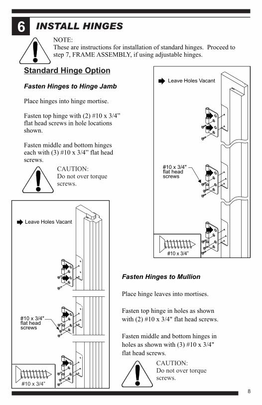
INSTALL HINGES6
Standard Hinge Option
NOTE:These are instructions for installation of standard hinges. Proceed tostep 7, FRAME ASSEMBLY, if using adjustable hinges.
Fasten Hinges to Hinge Jamb
Place hinges into hinge mortise.
Fasten top hinge with (2) #10 x 3/4”flat head screws in hole locationsshown.
Fasten middle and bottom hingeseach with (3) #10 x 3/4” flat headscrews.
Leave Holes Vacant
#10 x 3/4"flat headscrews
#10 x 3/4”
Fasten Hinges to Mullion
Place hinge leaves into mortises.
Fasten top hinge in holes as shown
with (2) #10 x 3/4" flat head screws.
Fasten middle and bottom hinges in
holes as shown with (3) #10 x 3/4"
flat head screws.
#10 x 3/4”
#10 x 3/4"flat headscrews
Leave Holes Vacant
CAUTION:Do not over torque screws.
CAUTION:Do not over torque screws.
8
FRAME ASSEMBLY7#10 x 2-1/2"
flat head screwsFasten Mullion to Head Jamb
Insert mullion into head jamb mortise.
Pre-drill 1/8” dia. pilot holes throughhead jamb into mullion.
Fasten with (3) #10 x 2-1/2” screwsthrough head jamb into mullion.
#10 x 2 1/2”flat headscrews
Apply End Seal Pads
Remove from paper backing andapply adhesive side of end sealpads at bottom of each jamb.
End seal pad
Caulk Entire Sill Gain
Apply a 1/4" bead of sealant to sillgain and a bead that matches profileof sill.
Fasten Side Jambs to Head Jamb
Butt and align head jamb to side jambs.
Pre-drill 1/8” dia. pilot holes through sidejamb into head jamb.
Fasten side jambs to head jamb with (3) #10 x 2 1/2” flat head screws through lock and hinge jamb into head jamb.
Sealant
Match profile of fixed portion of sill. Leave areas of adjusting riser free of caulk.
9
3/4"
2 ½" flat headscrews
#10 x 2-1/2"flat head screw
Sealant
Sealant
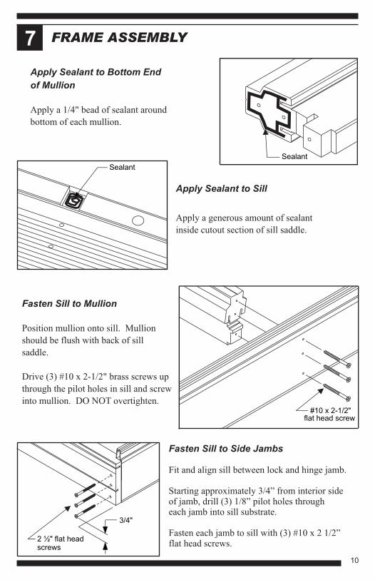
FRAME ASSEMBLY7
Apply Sealant to Sill
Apply a generous amount of sealant
inside cutout section of sill saddle.
Fasten Sill to Mullion
Position mullion onto sill. Mullion
should be flush with back of sill
saddle.
Drive (3) #10 x 2-1/2" brass screws up
through the pilot holes in sill and screw
into mullion. DO NOT overtighten.
Apply Sealant to Bottom End
of Mullion
Apply a 1/4" bead of sealant around
bottom of each mullion.
Fasten Sill to Side Jambs
Fit and align sill between lock and hinge jamb.
Starting approximately 3/4” from interior sideof jamb, drill (3) 1/8” pilot holes through each jamb into sill substrate.
Fasten each jamb to sill with (3) #10 x 2 1/2”flat head screws.
10
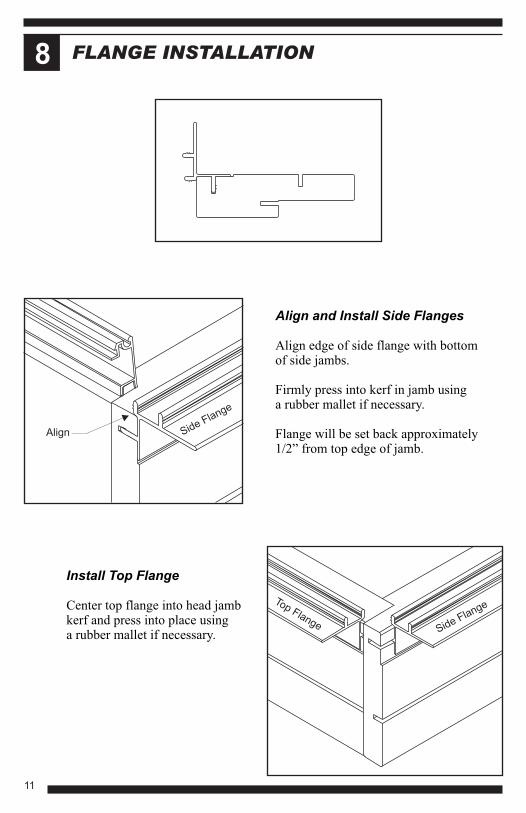
FLANGE INSTALLATION8
Align and Install Side Flanges
Align edge of side flange with bottomof side jambs.
Firmly press into kerf in jamb usinga rubber mallet if necessary.
Flange will be set back approximately1/2” from top edge of jamb.
Install Top Flange
Center top flange into head jambkerf and press into place usinga rubber mallet if necessary.
Side FlangeTop Flange
Side Flange
Align
11
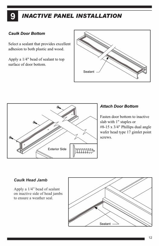
INACTIVE PANEL INSTALLATION9
Attach Door Bottom
Fasten door bottom to inactive
slab with 1" staples or
#8-15 x 3/4" Phillips dual angle
wafer head type 17 gimlet point
screws.
Exterior Side
Sealant
Caulk Door Bottom
Select a sealant that provides excellent
adhesion to both plastic and wood.
Apply a 1/4" bead of sealant to top
surface of door bottom.
Sealant
Caulk Head Jamb
Apply a 1/4” bead of sealanton inactive side of head jambsto ensure a weather seal.
12
Sealant
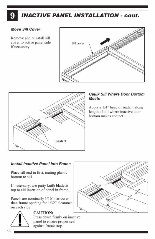
INACTIVE PANEL INSTALLATION - cont.9
Caulk Sill Where Door BottomMeets
Apply a 1/4” bead of sealant alonglength of sill where inactive doorbottom makes contact.
CAUTION:Press down firmly on inactive panel to ensure proper seal against frame stop.
Install Inactive Panel into Frame
Place sill end in first, mating plastic bottom to sill.
If necessary, use putty knife blade at top to aid insertion of panel in frame.
Panels are nominally 1/16” narrower than frame opening for 1/32” clearance on each side.
Move Sill Cover
Remove and reinstall sill cover to active panel side if necessary.
13
Sill cover
INACTIVE PANEL INSTALLATION - cont.9
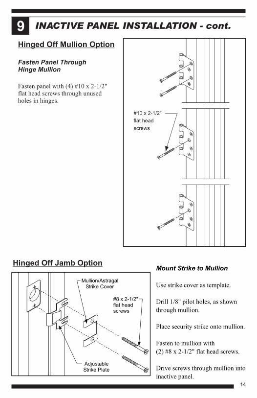
Fasten Panel Through Hinge Mullion
Fasten panel with (4) #10 x 2-1/2" flat head screws through unusedholes in hinges.
Mount Strike to Mullion
Use strike cover as template.
Drill 1/8" pilot holes, as shown
through mullion.
Place security strike onto mullion.
Fasten to mullion with
(2) #8 x 2-1/2" flat head screws.
Drive screws through mullion into
inactive panel.
Hinged Off Jamb Option
Hinged Off Mullion Option
#10 x 2-1/2"
flat head
screws
Mullion/AstragalStrike Cover
AdjustableStrike Plate
#8 x 2-1/2"flat headscrews
14
INACTIVE PANEL INSTALLATION - cont.9
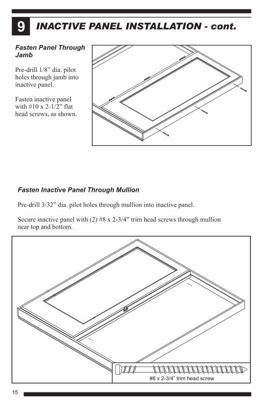
#8 x 2-3/4” trim head screw
Fasten Inactive Panel Through Mullion
Pre-drill 3/32” dia. pilot holes through mullion into inactive panel.
Secure inactive panel with (2) #8 x 2-3/4” trim head screws through mullionnear top and bottom.
Fasten Panel ThroughJamb
Pre-drill 1/8” dia. pilotholes through jamb intoinactive panel.
Fasten inactive panel with #10 x 2-1/2” flathead screws, as shown.
15
INSTALL COVE MOLDING10
7/16"
7/16"
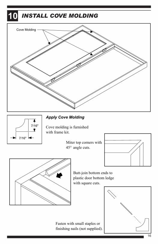
Cove Molding
Apply Cove Molding
Cove molding is furnished
with frame kit.
Miter top corners with
45° angle cuts.
Butt-join bottom ends to
plastic door bottom ledge
with square cuts.
Fasten with small staples or
finishing nails (not supplied).
16
ACTIVE PANEL INSTALLATION11
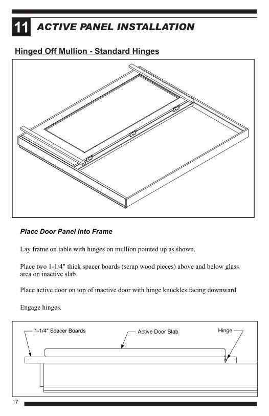
Place Door Panel into Frame
Lay frame on table with hinges on mullion pointed up as shown.
Place two 1-1/4" thick spacer boards (scrap wood pieces) above and below glassarea on inactive slab.
Place active door on top of inactive door with hinge knuckles facing downward.
Engage hinges.
Hinged Off Mullion - Standard Hinges
1-1/4" Spacer Boards Active Door Slab Hinge
17
ACTIVE PANEL INSTALLATION - cont.11
Hinged Off Mullion - Adjustable Hinges
Install Hinge Pins
Tap in pins. Becertain to insertso heads are ontop edges ofhinges.
Hinge Pin
#8 x 3/4”flat headscrews
#8 x 3/4”
Fasten door panel to mullion
Place two spacer boards on top of inactive panel then lay active panel on top of spacer boards aligning hinges into mortises in mullion.
Fasten door panel to mullion with #8 x 3/4” flat head screws, (2) in top hinge and (3) in middle and bottom hinge.
18
ACTIVE PANEL INSTALLATION - cont.11
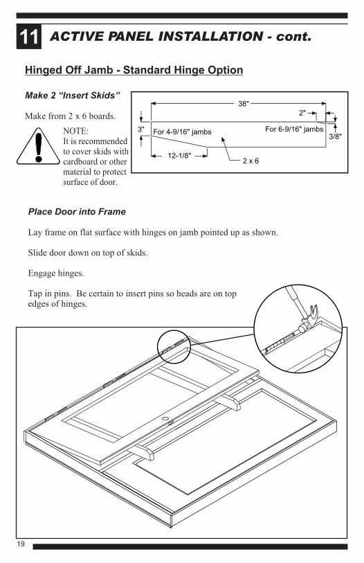
Place Door into Frame
Lay frame on flat surface with hinges on jamb pointed up as shown.
Slide door down on top of skids.
Engage hinges.
Tap in pins. Be certain to insert pins so heads are on topedges of hinges.
Make 2 “Insert Skids”
Make from 2 x 6 boards.
Hinged Off Jamb - Standard Hinge Option
NOTE:It is recommendedto cover skids withcardboard or othermaterial to protectsurface of door.
38"
2"
3"
12-1/8"
For 4-9/16" jambs For 6-9/16" jambs
2 x 6
3/8"
19
ACTIVE PANEL INSTALLATION - cont.11
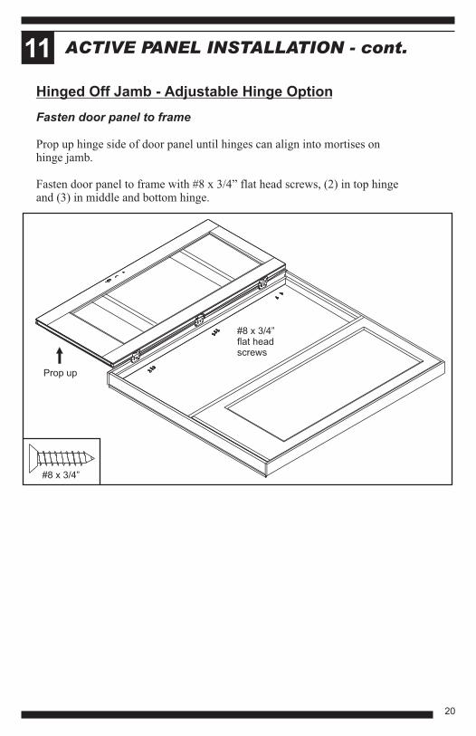
Hinged Off Jamb - Adjustable Hinge Option
Fasten door panel to frame
Prop up hinge side of door panel until hinges can align into mortises on hinge jamb.
Fasten door panel to frame with #8 x 3/4” flat head screws, (2) in top hinge and (3) in middle and bottom hinge.
#8 x 3/4”flat headscrews
Prop up
#8 x 3/4”
20
Standard Lock Option
Attach Transport Clip to Door
Insert tab into latch bore,
Position reference lip at edge ofstile against exterior side of door.
Fasten with (2) #6 x 3/4” flat headscrews.
Multi-point Lock Option
Attach Transport Clip to Frame
Close door into frame ensuringmargins are even at head jamb.
Fasten transport clip to framewith (2) #6 x 3/4” flat head screws.
#6 x 3/4"flat headscrews
Transport Clip
Exteriorside
#6 x 3/4"flat headscrews
Transport Clip
Flatten lock tab with hammer.
#6 x 3/4”
Flatten withhammer
ACTIVE PANEL INSTALLATION - cont.11
21
ACTIVE PANEL INSTALLATION - cont.11
UNIT READY FOR INSTALLATION12
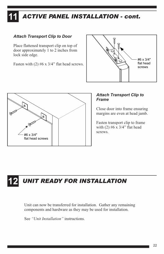
Attach Transport Clip to Frame
Close door into frame ensuringmargins are even at head jamb.
Fasten transport clip to framewith (2) #6 x 3/4” flat head screws.
Unit can now be transferred for installation. Gather any remaining components and hardware as they may be used for installation.
See “Unit Installation” instructions.
#6 x 3/4"flat headscrews
Attach Transport Clip to Door
Place flattened transport clip on top of door approximately 1 to 2 inches fromlock side edge.
Fasten with (2) #6 x 3/4” flat head screws.
#6 x 3/4"flat head screws
22
1687 Woodlands Dr. Maumee, OH 435371-800-THERMATRU (843-7628)