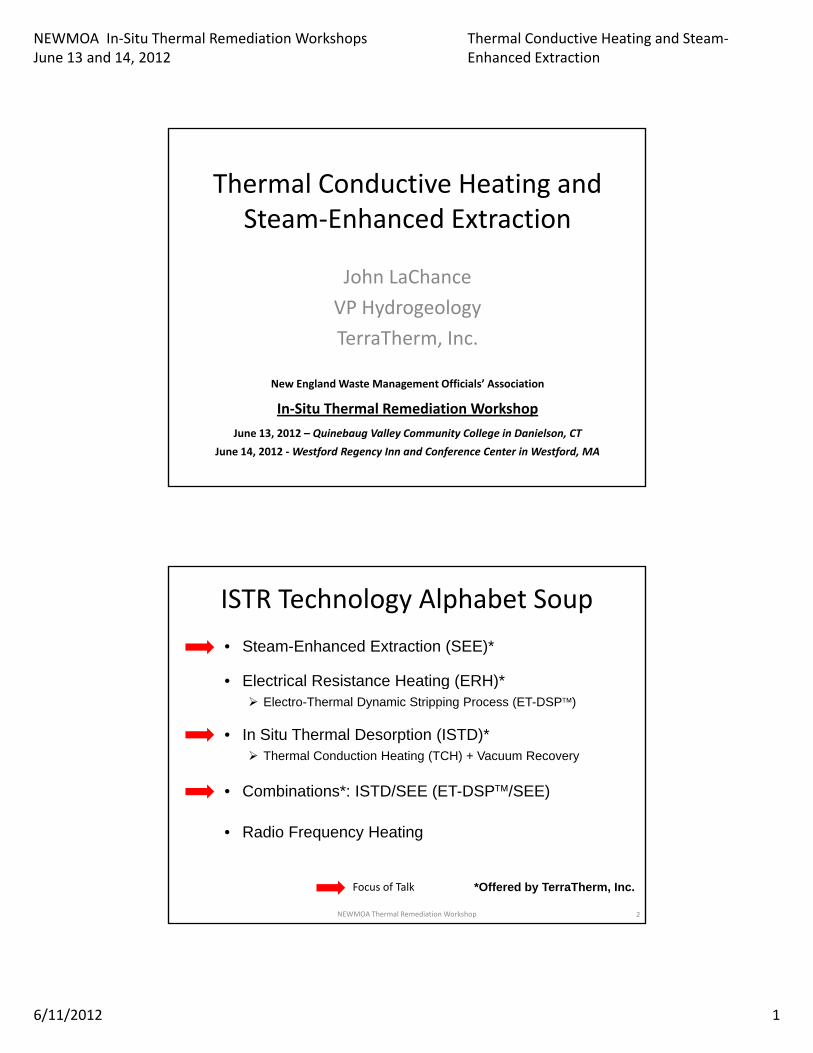
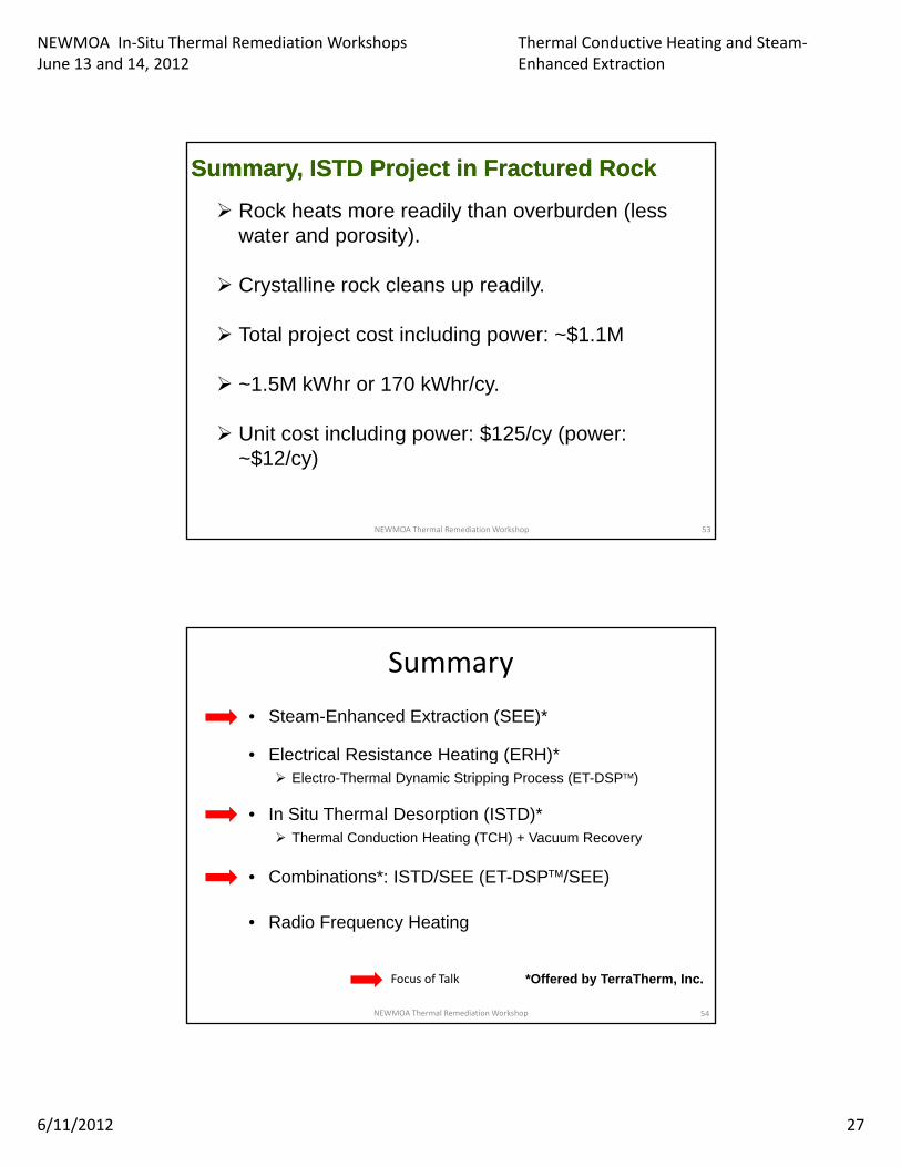
NEWMOA In-Situ Thermal Remediation Workshops June 13 and 14, 2012 Thermal Conductive Heating and Steam- Enhanced Extraction 6/11/2012 1 Thermal Conductive Heating and Steam-Enhanced Extraction John LaChance VP Hydrogeology TerraTherm, Inc. New England Waste Management Officials’ Association In-Situ Thermal Remediation Workshop June 13, 2012 – Quinebaug Valley Community College in Danielson, CT June 14, 2012 - Westford Regency Inn and Conference Center in Westford, MA ISTR Technology Alphabet Soup • Steam-Enhanced Extraction (SEE)* • Electrical Resistance Heating (ERH)* Electrical Resistance Heating (ERH) Electro-Thermal Dynamic Stripping Process (ET-DSP) • In Situ Thermal Desorption (ISTD)* Thermal Conduction Heating (TCH) + Vacuum Recovery • Combinations*: ISTD/SEE (ET-DSP/SEE) • Radio Frequency Heating Focus of Talk *Offered by TerraTherm, Inc. 2 NEWMOA Thermal Remediation Workshop
Transcript
NEWMOA In-Situ Thermal Remediation WorkshopsJune 13 and 14, 2012
Thermal Conductive Heating and Steam-Enhanced Extraction
6/11/2012 1
Thermal Conductive Heating and Steam-Enhanced Extraction
John LaChanceVP HydrogeologyTerraTherm, Inc.
New England Waste Management Officials’ Association
In-Situ Thermal Remediation WorkshopJune 13, 2012 – Quinebaug Valley Community College in Danielson, CT
June 14, 2012 - Westford Regency Inn and Conference Center in Westford, MA
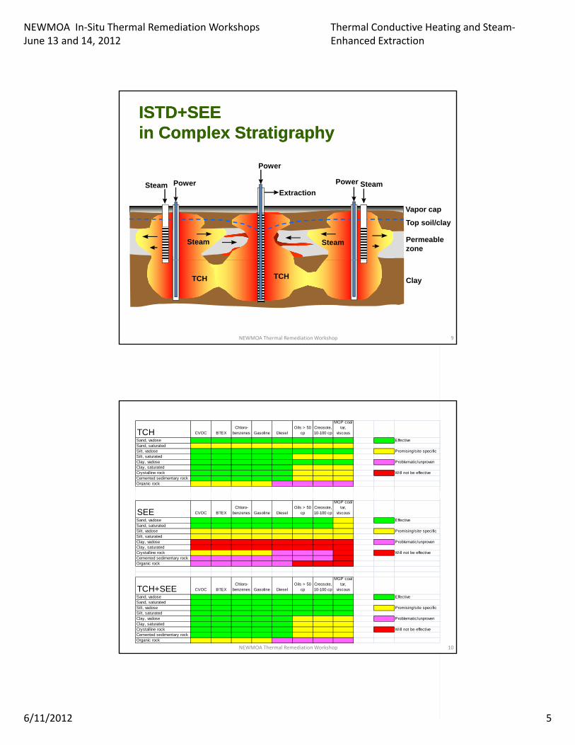
Sand, vadose EffectiveSand, saturatedSilt, vadose Promising/site specificSilt, saturatedClay, vadose Problematic/unprovenClay, saturatedCrystalline rock Will not be effectiveCemented sedimentary rockOrganic rockOrganic rock
SEE CVOC BTEXChloro-
benzenes Gasoline DieselOils > 50
cpCreosote, 10-100 cp
MGP coal tar,
viscous
Sand, vadose EffectiveSand, saturatedSilt, vadose Promising/site specificSilt, saturatedClay, vadose Problematic/unprovenClay, saturatedCrystalline rock Will not be effectiveCemented sedimentary rockOrganic rock
TCH+SEE CVOC BTEXChloro-
benzenes Gasoline DieselOils > 50
cpCreosote, 10-100 cp
MGP coal tar,
viscous
Sand, vadose EffectiveSand, saturatedSilt, vadose Promising/site specificSilt, saturatedClay, vadose Problematic/unprovenClay, saturatedCrystalline rock Will not be effectiveCemented sedimentary rockOrganic rock
10NEWMOA Thermal Remediation Workshop
NEWMOA In-Situ Thermal Remediation WorkshopsJune 13 and 14, 2012
Thermal Conductive Heating and Steam-Enhanced Extraction
6/11/2012 6
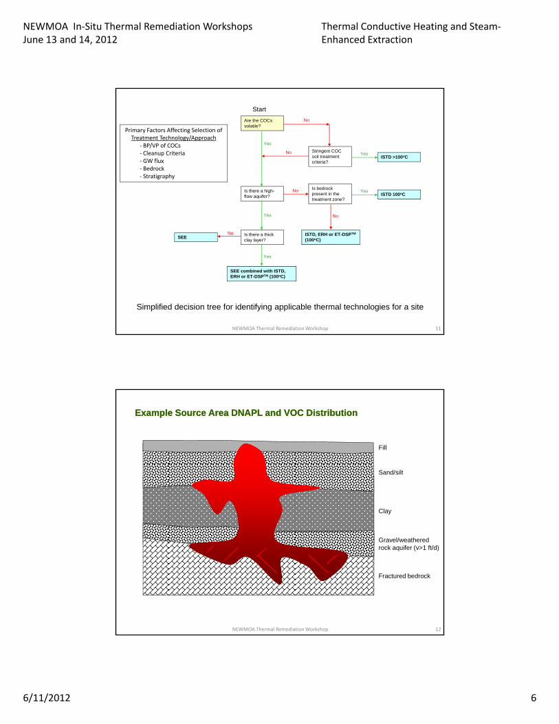
Are the COCs volatile?
ISTD >100oC
No
No Yes
Yes
Stringent COC soil treatment criteria?
Start
Primary Factors Affecting Selection of Treatment Technology/Approach
- BP/VP of COCs- Cleanup Criteria - GW flux- Bedrock
Is there a high-flow aquifer?
ISTD, ERH or ET-DSPTM
(100oC)
ISTD 100oC
Is there a thick clay layer?
SEE
No
No
Yes
No
Yes
Is bedrock present in the treatment zone?
Bedrock- Stratigraphy
SEE combined with ISTD, ERH or ET-DSPTM (100oC)
Simplified decision tree for identifying applicable thermal technologies for a site
Yes
11NEWMOA Thermal Remediation Workshop
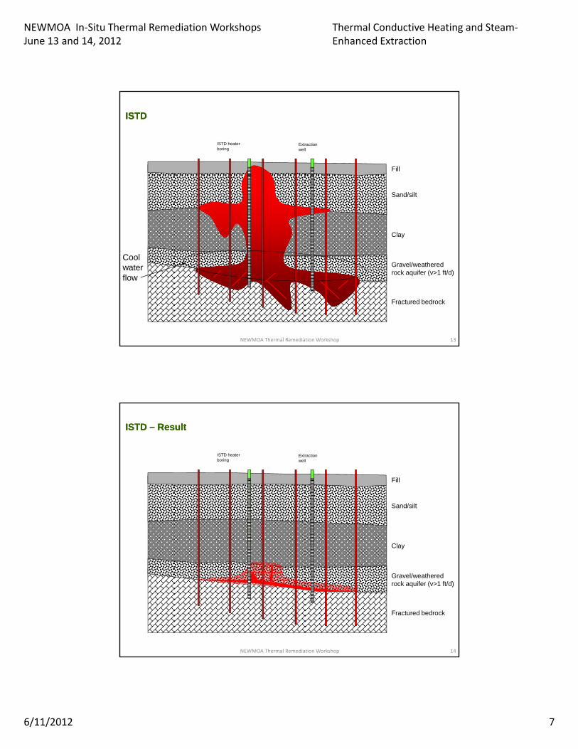
Fill
S d/ ilt
Example Source Area DNAPL and VOC DistributionExample Source Area DNAPL and VOC Distribution
Sand/silt
Clay
Gravel/weathered rock aquifer (v>1 ft/d)
Fractured bedrock
12NEWMOA Thermal Remediation Workshop
NEWMOA In-Situ Thermal Remediation WorkshopsJune 13 and 14, 2012
Thermal Conductive Heating and Steam-Enhanced Extraction
6/11/2012 7
Fill
ISTDISTD
Extraction well
ISTD heater boring
Sand/silt
Clay
Cool Gravel/weathered rock aquifer (v>1 ft/d)
Fractured bedrock
water flow
13NEWMOA Thermal Remediation Workshop
Fill
ISTD ISTD –– ResultResult
Extraction well
ISTD heater boring
Sand/silt
Clay
Gravel/weathered rock aquifer (v>1 ft/d)
Fractured bedrock
14NEWMOA Thermal Remediation Workshop
NEWMOA In-Situ Thermal Remediation WorkshopsJune 13 and 14, 2012
Thermal Conductive Heating and Steam-Enhanced Extraction
6/11/2012 8
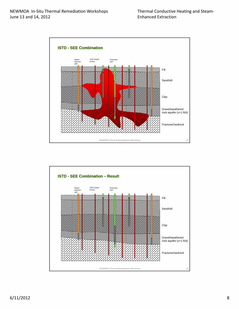
Fill
ISTD ISTD -- SEE CombinationSEE Combination
Steam injection well
Extraction well
ISTD heater boring
Sand/silt
Clay
Gravel/weathered rock aquifer (v>1 ft/d)
Fractured bedrock
15NEWMOA Thermal Remediation Workshop
Fill
ISTD ISTD -- SEE Combination SEE Combination –– ResultResult
Steam injection well
Extraction well
ISTD heater boring
Sand/silt
Clay
Gravel/weathered rock aquifer (v>1 ft/d)
Fractured bedrock
16NEWMOA Thermal Remediation Workshop
NEWMOA In-Situ Thermal Remediation WorkshopsJune 13 and 14, 2012
Thermal Conductive Heating and Steam-Enhanced Extraction
6/11/2012 9
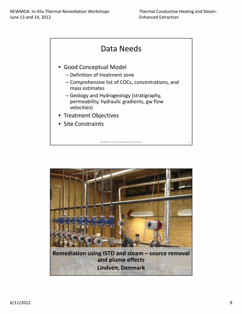
Data Needs
• Good Conceptual ModelD fi iti f t t t– Definition of treatment zone
– Comprehensive list of COCs, concentrations, and mass estimates
NEWMOA In-Situ Thermal Remediation WorkshopsJune 13 and 14, 2012
Thermal Conductive Heating and Steam-Enhanced Extraction
6/11/2012 28
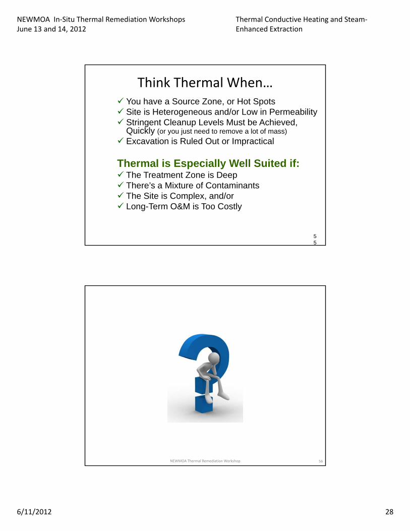
Think Thermal When… You have a Source Zone, or Hot Spots Site is Heterogeneous and/or Low in Permeability Stringent Cleanup Levels Must be Achieved,Stringent Cleanup Levels Must be Achieved,
Quickly (or you just need to remove a lot of mass)
Excavation is Ruled Out or Impractical
Thermal is Especially Well Suited if: The Treatment Zone is Deep There’s a Mixture of Contaminants There s a Mixture of Contaminants The Site is Complex, and/or Long-Term O&M is Too Costly
55
NEWMOA Thermal Remediation Workshop 56
NEWMOA In-Situ Thermal Remediation WorkshopsJune 13 and 14, 2012
Thermal Conductive Heating and Steam-Enhanced Extraction
6/11/2012 29
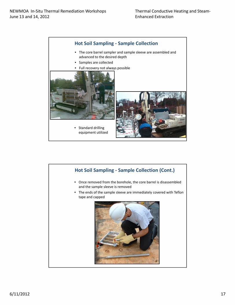
SUPPLEMENTAL MATERIAL -HOT SOIL SAMPLING
Griepke-Nielsen, S., et al, Remediation of Chlorinated and Recalcitrant Compounds, Monterey, CA. 2012
NEWMOA Thermal Remediation Workshop 57
Soil Sampling during and after Thermal –How and When?
Steffen Griepke Nielsen, Pia Juul Jensen (formerly NIRAS A/S, Alleroed, Denmark)Gorm Heron (TerraTherm, Inc., Bakersfield, CA USA)
Jim Galligan and John LaChance (TerraTherm, Inc., Gardner, MA USA)Peder Johansen (Capital Region of Denmark, Hillerød, Denmark)
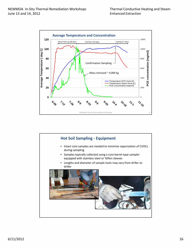
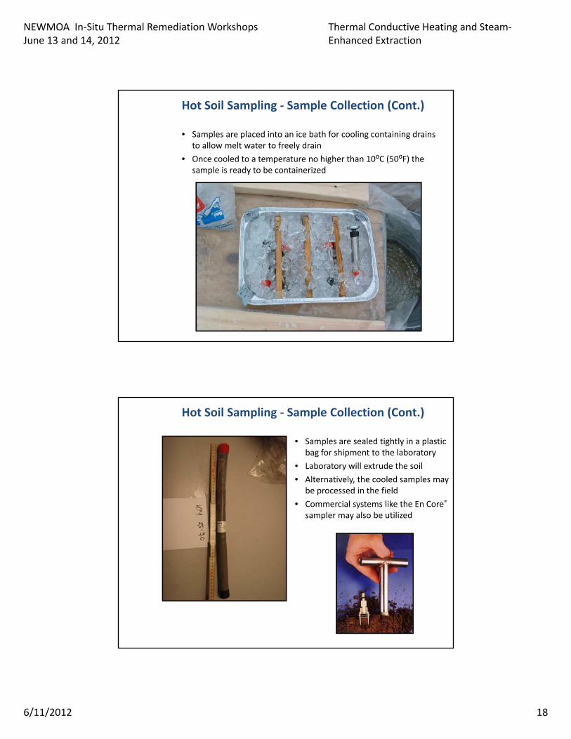
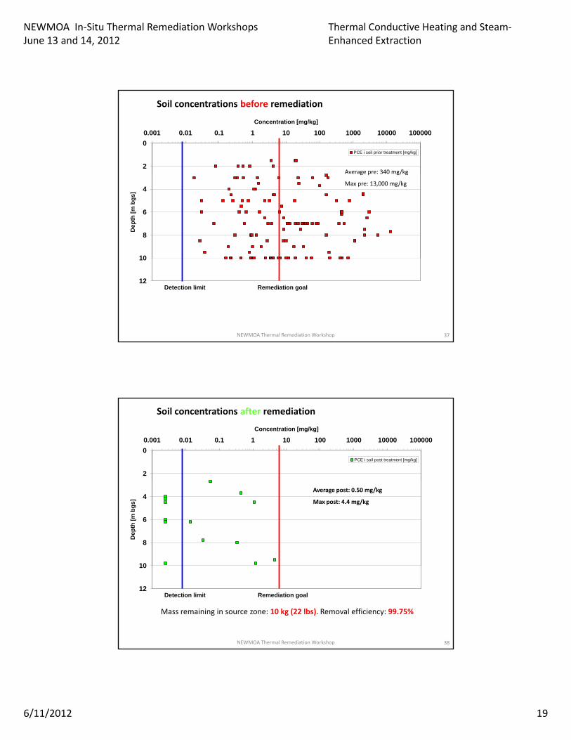
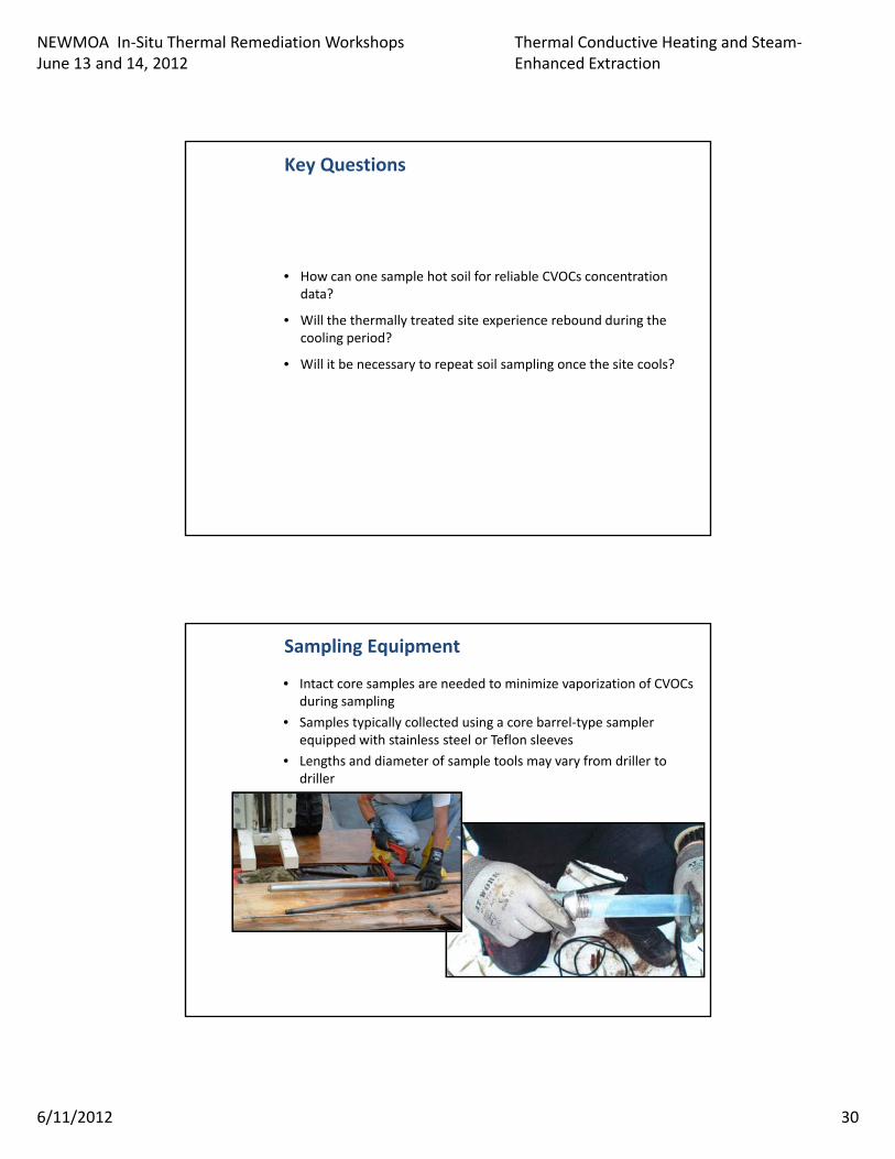
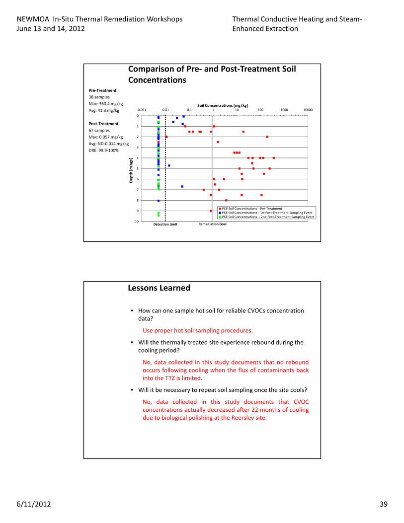
• How can one sample hot soil for reliable CVOCs concentration data?
Use proper hot soil sampling procedures.
Will h h ll d i i b d d i h• Will the thermally treated site experience rebound during the cooling period?
No, data collected in this study documents that no reboundoccurs following cooling when the flux of contaminants backinto the TTZ is limited.
• Will it be necessary to repeat soil sampling once the site cools?
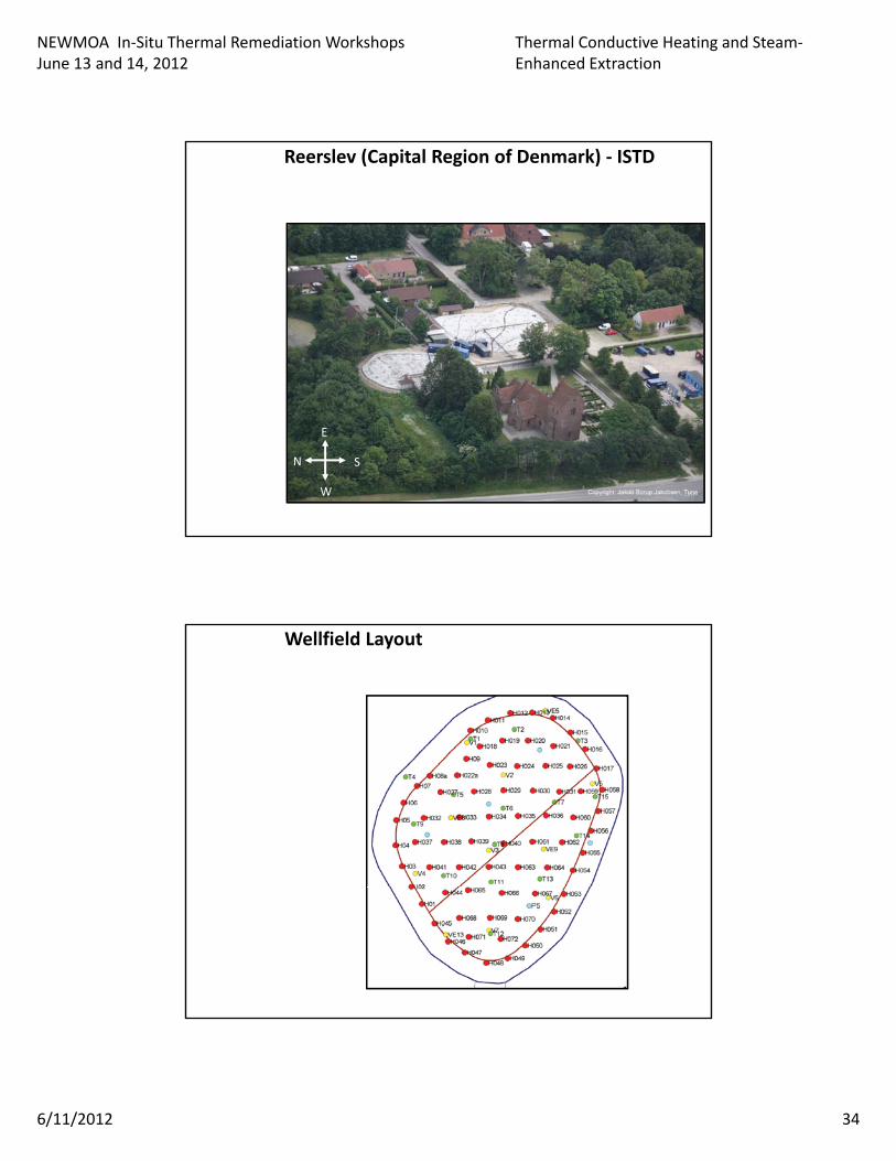
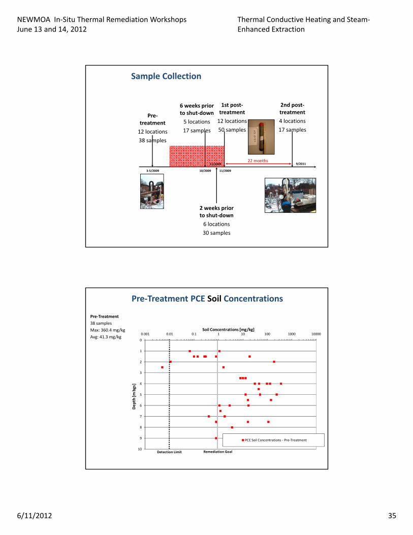
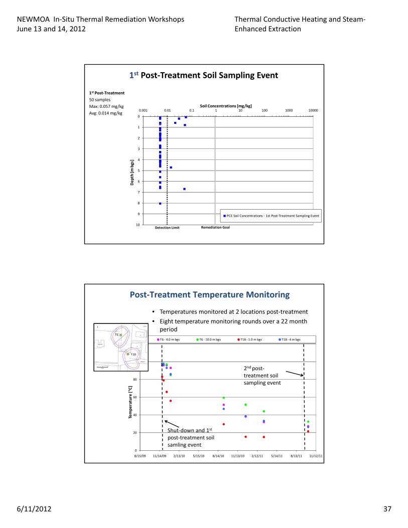
N d ll d i hi d d h CVOCNo, data collected in this study documents that CVOCconcentrations actually decreased after 22 months of coolingdue to biological polishing at the Reerslev site.
NEWMOA In-Situ Thermal Remediation WorkshopsJune 13 and 14, 2012
Thermal Conductive Heating and Steam-Enhanced Extraction
6/11/2012 40
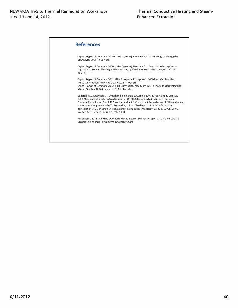
Capital Region of Denmark. 2008a. MW Gjøes Vej, Reerslev. Forklassificerings-undersøgelse. NIRAS. May 2008 (in Danish).
Capital Region of Denmark. 2008b. MW Gjøes Vej, Reerslev. Supplerende Undersøgelser –Supplerende Forklassificering, Risikovurdering og Ventilationstest. NIRAS, August 2008 (in Danish)
References
Danish).
Capital Region of Denmark. 2011. ISTD Entreprise, Entreprise 1, MW Gjøes Vej, Reerslev. Slutdokumentation. NIRAS. February 2011 (in Danish).Capital Region of Denmark. 2012. ISTD Oprensning, MW Gjøes Vej, Reerslev. Jordprøvetagning i Afkølet Område. NIRAS. January 2012 (in Danish).
Gaberell, M., A. Gavaskar, E. Drescher, J. Sminchak, L. Cumming, W.-S. Yoon, and S. De Silva. 2002. “Soil Core Characterization Strategy at DNAPL Sites Subjected to Strong Thermal or Chemical Remediation.” in: A.R. Gavaskar and A.S.C. Chen (Eds.), Remediation of Chlorinated and Recalcitrant Compounds—2002. Proceedings of the Third International Conference on Remediation of Chlorinated and Recalcitrant Compounds (Monterey, CA; May 2002). ISBN 1-57477-132-9. Battelle Press, Columbus, OH.
TerraTherm. 2011. Standard Operating Procedure. Hot Soil Sampling for Chlorinated Volatile Organic Compounds. TerraTherm. December 2009.