THERMAL CONDUCTIVITY Of PAPER 110NIEYCOM113 CORES AND SOUND ABSORPTION OF SANIDWICI-I PANELS Information Reviewed and Reaffirmed September 1961 No. 1952 FOREST PRODUCTS LABORATORY UNITED STATES DEPARTMENT OF AGRICULTURE FOREST SERVICE In Cooperation with the University of Wisconsin MADISON 5, WISCONSIN
Transcript
THERMAL CONDUCTIVITY Of PAPER
110NIEYCOM113 CORES AND SOUND
ABSORPTION OF SANIDWICI-I PANELS
Information Reviewed and Reaffirmed
September 1961
No. 1952
FOREST PRODUCTS LABORATORY UNITED STATES DEPARTMENT OF AGRICULTURE
FOREST SERVICE
In Cooperation with the University of Wisconsin MADISON 5, WISCONSIN
THERMAL CONDUCTIVITY OF PAPER HONEYCOMB CORES AND
SOUND ABSORPTION OF SANDWICH PANELS1.
By
D. J. FAHEY, TechnologistM. E. DUNLAP, Engineer
andR. J. SEIDL, Chemical Engineer
Forest Products Laboratory,..?_ Forest ServiceU. S. Department of Agriculture
ado • =Ye elm
Summary
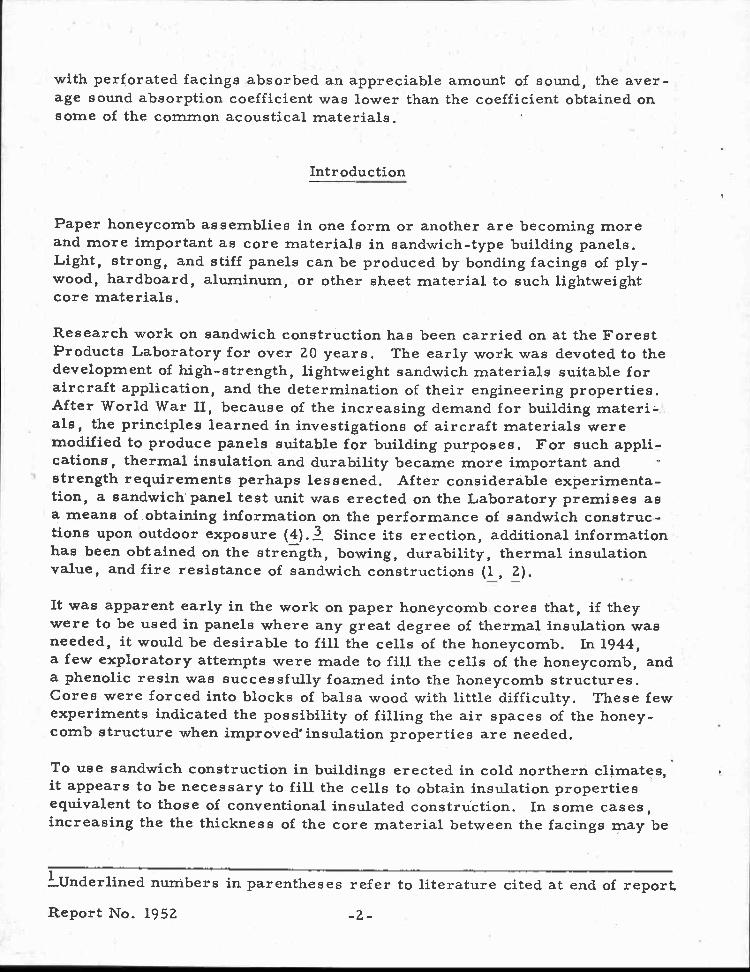
This paper presents results of research work on thermal conductivity ofpaper honeycomb cores and ways of improving their insulation value. Inaddition, there are data on sound absorption of sandwich panels havingsolid and perforated facings.
The thermal insulation values of a honeycomb core depended on the type ofconstruction and its density. Filling the cells with foamed-in-place resinor with fill materials resulted in some improvement in the thermal insula-tion value. The lowest value obtained compared favorably with that of com-mon mineral-wool products.
Sandwich panels faced with hard facings, such as hardboard, had relativelyno sound absorption properties. Incorporating artificial perforations in onefacing similar to those in ordinary acoustical tile, however, resulted in anappreciable increase in the amount of sound the panel absorbed. Utilizingthe natural holes in white-pocket Douglas-fir veneer was also effective inincreasing the acoustical value of the panel. Although the sandwich panels
1Report originally dated September 1953.
—Maintained at Madison, Wis. , in cooperation with the University ofWisconsin.
Report No. 1952
with perforated facings absorbed an appreciable amount of sound, the aver-age sound absorption coefficient was lower than the coefficient obtained onsome of the common acoustical materials.
Introduction
Paper honeycomb assemblies in one form or another are becoming moreand more important as core materials in sandwich-type building panels.Light, strong, and stiff panels can be produced by bonding facings of ply-wood, hardboard, aluminum, or other sheet material to such lightweightcore materials.
Research work on sandwich construction has been carried on at the ForestProducts Laboratory for over 20 years. The early work was devoted to thedevelopment of high-strength, lightweight sandwich materials suitable foraircraft application, and the determination of their engineering properties.After World War II, because of the increasing demand for building materi-,als, the principles learned in investigations of aircraft materials weremodified to produce panels suitable for building purposes. For such appli-cations, thermal insulation and durability became more important and -strength requirements perhaps lessened. After considerable experimenta-tion, a sandwich panel test unit was erected on the Laboratory premises asa means of obtaining information on the performance of sandwich construc-tions upon outdoor exposure (4). 3 Since its erection, additional informationhas been obtained on the strength, bowing, durability, thermal insulationvalue, and fire resistance of sandwich constructions (1 , 2).
It was apparent early in the work on paper honeycomb cores that, if theywere to be used in panels where any great degree of thermal insulation wasneeded, it would be desirable to fill the cells of the honeycomb. In 1944,a few exploratory attempts were made to fill the cells of the honeycomb, anda phenolic resin was successfully foamed into the honeycomb structures.Cores were forced into blocks of balsa wood with little difficulty. These fewexperiments indicated the possibility of filling the air spaces of the honey-comb structure when improved' insulation properties are needed.
To use sandwich construction in buildings erected in cold northern climates,it appears to be necessary to fill the cells to obtain insulation propertiesequivalent to those of conventional insulated construction. In some cases,increasing the the thickness of the core material between the facings may be
LUnderlined numbers in parentheses refer to literature cited at end of report.
Report No. 1952 -2-
the. most economical way of improving insulation properties; in other casesit may not be practical.
When sandwich construction was first considered for building material inpartitions and doors, its ability to absorb or transmit sound was oftenquestioned. Most of these panels would have very little inherent sound-absorbing properties because of the hard-surfaced facings and the low massof the panels. These properties might be improved, however, by means ofperforations in one of the exposed faces or by special core constructions.
This report summarizes investigations of (1) ways of improving the thermalinsulating properties of the cores by filling the openings with low-densityfoam or fill materials and (2) sound absorption properties of sandwich con-struction as affected by the core and the facings.
Materials
Honeycomb Core
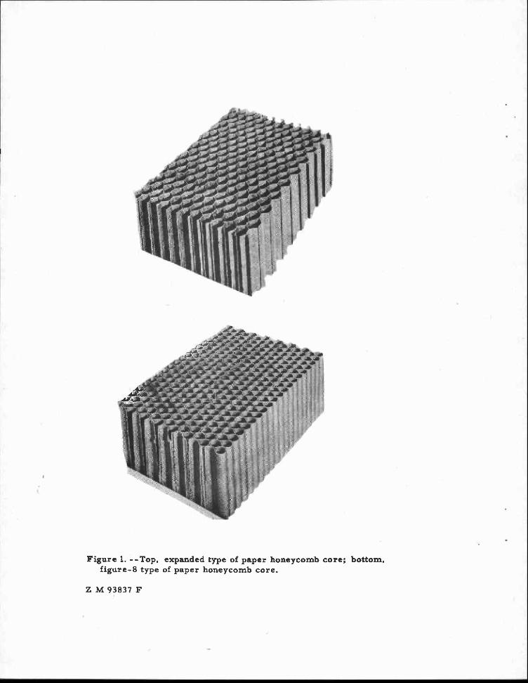
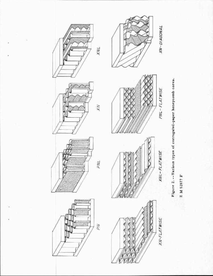
Paper can be converted to honeycomb core in a number of different ways,The expanded type is made by interspacing sheets of treated paper withparallel and uniformly spaced strips of adhesive and expanding the assembly,after bonding, to form a core with hexagonal cell sections (fig. 1, top).Another type is made by looping and bonding sheets of resin-treated paperto form circular cells representing a "figure 8" in cross section (fig. 1,bottom). From assemblies of sheets of corrugated paper, a number ofdifferent core constructions are also possible, some easier than others tofabricate. Eight of such constructions are shown in figure 2. Most of theexperiments reported herein were made with the corrugated core.
A kraft paper weighing 20, 30, or 50 pounds per 3,000 square feet wastreated with 15 percent of a water-soluble phenolic resin (based on thetotal weight of resin and fiber). The paper was corrugated on A-flutecorrugating rolls (approximately three flutes per inch) and assembled intoblocks with a phenolic adhesive. In some cases, a flat sheet of treatedpaper was inserted between the corrugated sheets.
Filling the Cells of the Honeycomb
There are a number of different ways of filling the opening of the cells, in-cluding foaming resin into the cells, filling cells with finely granulatedinsulating material, or forcing the core into blocks of low-density material.
Report No. 1952 -3-
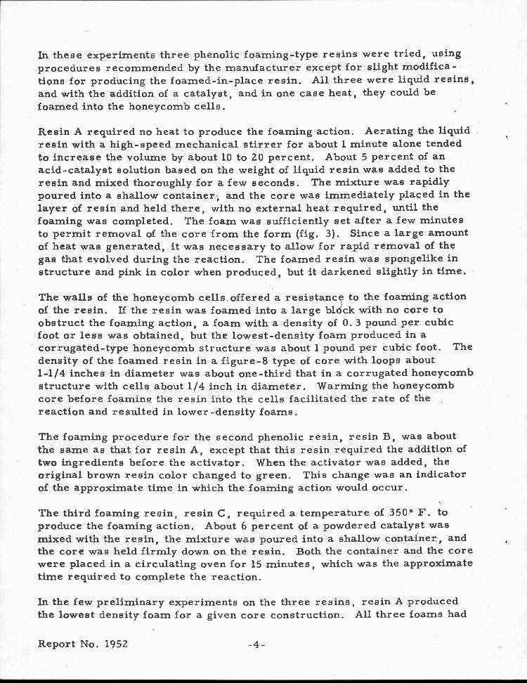
In these experiments three phenolic foaming-type resins were tried, usingprocedures recommended by the manufacturer except for slight modifica-tions for producing the foamed-in-place resin. All three were liquid resins,and with the addition of a catalyst, and in one case heat, they could befoamed into the honeycomb cells.
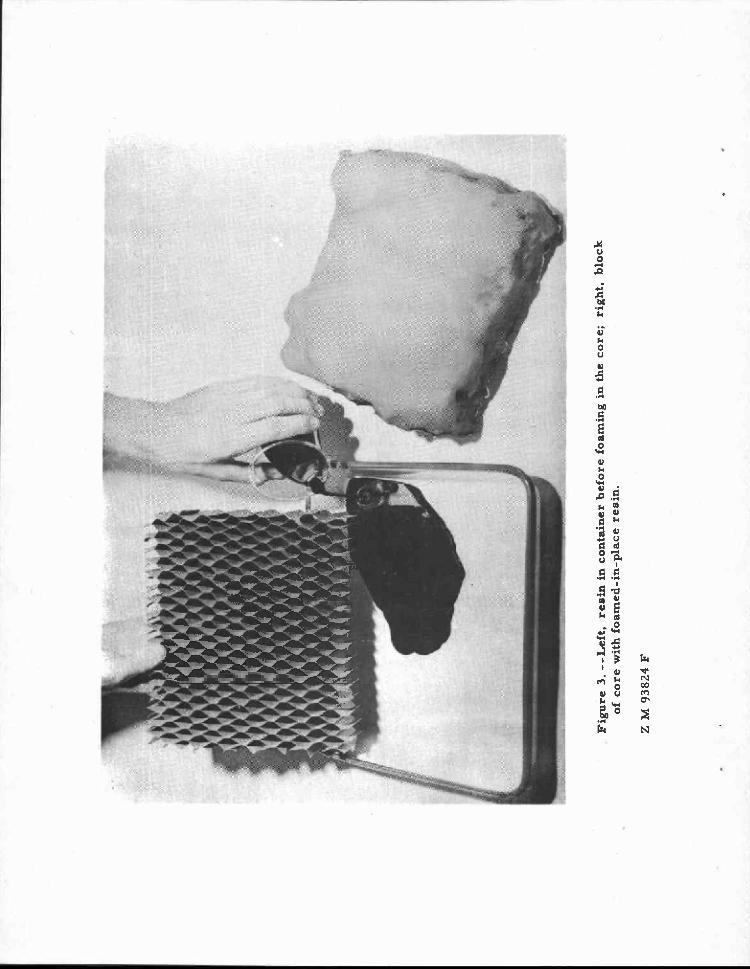
Resin A required no heat to produce the foaming action. Aerating the liquidresin with a high-speed mechanical stirrer for about 1 minute alone tendedto increase the volume by about 10 to 20 percent. About 5 percent of anacid-catalyst solution based on the weight of liquid resin was added to theresin and mixed thoroughly for a few seconds. The mixture was rapidlypoured into a shallow container, and the core was immediately placed in thelayer of resin and held there, with no external heat required, until thefoaming was completed. The foam was sufficiently set after a few minutesto permit removal of the core from the form (fig. 3). Since a large amountof heat was generated, it was necessary to allow for rapid removal of thegas that evolved during the reaction. The foamed resin was spongelike instructure and pink in color when produced, but it darkened slightly in time.
The walls of the honeycomb cells offered a resistance to the foaming actionof the resin. If the resin was foamed into a large bldck with no core toobstruct the foaming action, a foam with a density of 0.3 pound per cubicfoot or less was obtained, but the lowest-density foam produced in acorrugated-type honeycomb structure was about 1 pound per cubic foot. Thedensity of the foamed resin in a figure-8 type of core with loops about1-1/4 inches in diameter was about one-third that in a corrugated honeycombstructure with cells about 1/4 inch in diameter. Warming the honeycombcore before foaming the resin into the cells facilitated the rate of thereaction and resulted in lower-density foams.
The foaming procedure for the second phenolic resin, resin B, was aboutthe same as that for resin A, except that this resin required the addition oftwo ingredients before the activator. When the activator was added, theoriginal brown resin color changed to green. This change was an indicatorof the approximate time in which the foaming action would occur.
The third foaming resin, resin C, required a temperature of 350° F. toproduce the foaming action. About 6 percent of a powdered catalyst wasmixed with the resin, the mixture was poured into a shallow container, andthe core was held firmly down on the resin. Both the container and the corewere placed in a circulating oven for 15 minutes, which was the approximatetime required to complete the reaction.
In the few preliminary experiments on the three resins, resin A producedthe lowest density foam for a given core construction. All three foams had
Report No. 1952 -4-
low water absorption. In addition to improvement of thermal insulation, animprovement in the fire resistance of the panel can be realized with foamed-in-place resins. The combustibility of a panel should also be lessened.Depending on the density of the foam, an improvement in compressivestrength of the core has also been obtained.
In large-scale production of resin-filled core it may be possible to spotdroplets of catalyzed resin on a rapidly moving corrugated web that it inthe process of being assembled into core, or to deposit droplets of catalyzedresin into cells of the assembled core, so that with proper timing the foamwould fill the cells and provide the inherent benefits.
Three commercial, relatively low-density, granulated fill materials wereinvestigated to determine their effect on improving the insulating value ofhoneycomb core. The following were tried: (a) Silica aerogel fill insula-tion, (b) shredded urea formaldehyde foam, and (c) siliceous volcanic rockmaterial heated to make it expand to a light and fluffy mass. Test panelsof honeycomb core, 14 by 14 inches in area and 1 inch thick, were prepared.A thin kraft paper was bonded to one surface of the panel to hold the fillmaterial in the cells. The various fill materials were then sifted into theopenings from the other surface. The cores were vibrated slightly tofacilitate filling the cells. The puffed siliceous material was moregranular than the other two fill materials and seemed to fill the cells withthe least vibrating. After the cells were filled, a similar kraft paper wasbonded to the other surface.
A few Laboratory attempts to fill 8-foot-long sections of complete sandwichpanels having a certain type of corrugated core demonstrated that it wouldbe feasible to fill commerical-size panels after the facings have been bond-ed to the core. A panel with the core having one-half of the flutes parallelto the 8-foot length and the remaining flutes perpendicular to the facings wasused for these trials. With the higher density granular materials, no partic-ular difficulty was experienced in filling the panel by permitting the granulesto sift down the 8 feet of open path. With the lower density material (pulver-ized urea foam), the first attempts were unsuccessful, but the panel wasfinally filled by placing it against a vibrator as the fill material was added.
Since lower density foams could be obtained by foaming resin into largeblocks (without the core) than by foaming in place in a honeycomb structure,attempts were made to force the core into preformed blocks of the low-density phenolic foam. This practice was unsuccessful with these threephenolic foams because of their spongy nature. A foamed polystyrene, balsawood, and foamed rubber materials, however, were successfully forced in-to small samples of core.
-5-
Panels for Sound Absorption Tests
Eight sandwich panels, with various arrangements of the corrugated type ofcore, were prepared for sound absorption tests. Details as to type of corearrangement and facings for the different test panels are given in table 3.The core in all panels was made from 50-pound paper with 15 percent ofresin. Since perforated surfaces are known to favor sound absorption,panels with hardboard facings were tested with and without perforations.The perforations were made by drilling 3/16-inch-diameter holes about 5/16inch apart in one of the facings; no holes were drilled in the other facing.The perforated facing contained approximately 510 holes per square foot. Analuminum-faced panel with one facing perforated in the same manner wasalso tested. The natural holes in white-pocket Douglas-fir veneer were alsoutilized in two test panels. Veneer 1/16 inch thick that was cut from heavy-white-pocket wood had numerous holes and pockets. This veneer was bondedto one side of a panel, and the other facing was made from light-white-pocket Douglas-fir veneer with practically no holes.
In sandwich panels for structural application, the core is usually placed inthe panel with part or all of the flutes of the corrugated sheet perpendicularto the facing, leaving direct channels from one facing to the other. It wasthought that if such cores were placed with flutes on a diagonal to the facings,the sound waves entering the panel would be deflected by the walls of cells,and the sound-absorbing properties of ithe panel would be improved. Threepanels were thus prepared for test in which the core was placed with flutesrunning at a 45° angle instead of 90° to the facing.
The cores were bonded to the hardboard and veneer facings with an acid-catalyzed, high-temperature-setting, phenolic resin adhesive. The resinwas applied to both the facings and the core, and the panel pressed in a hotpress using low pressure. In gluing the core to the aluminum facings, ahigh-temperature-setting vinyl-phenolic glue formulation was used. Thetemperature of the press was about 300° F. , but the panel was cooled underpressure before it was removed from the press.
Method of Test
Thermal Insulation
Thermal insulation tests of sandwich panels were conducted in the ForestProducts Laboratory thermal conductivity apparatus, which consists of aheated central plate, 13-1/2 by 13-1/2 inches, having two separate heatsources, one serving the center section, or test area (8 by 8 inches), and
Report No. 1952 -6-
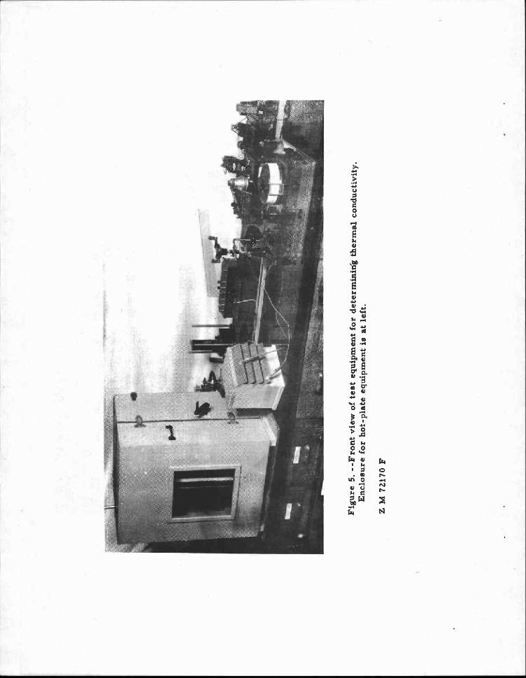
the other the border, or frame, which serves as a guard ring (fig. 4). Twosamples were tested at a time and were placed on opposite sides of theheated plate. Movable water-cooled plates were placed in contact with thesamples. The heat flow with this arrangement was established from theheated center plate to the cooled outside plates. The amount of electricalenergy supplied to the test area and guard ring was adjusted by potentio-meters, so that the surface temperatures of the test area and guard ringwere practically the same. When this adjustment was reached, the heatflow across the test sample was assumed to be uninfluenced by the area ofthe sample opposite the guard ring. In other words, the flow of heat wasuniform over the test area and there was no loss of heat from the test areato the guard-ring zone. The auxiliary apparatus is shown in figure 5.
Samples approximately 1 inch thick were tested between a hot-plate tempera-ture of 102° F. and a cold-plate temperature of 55° F. The mean tempera-ture was about 78° F.
Sound Absorption Tests
Sound absorption tests reported herein were made by the National Bureau ofStandards. The so-called "box test" was employed. It is used in experi-mental and developmental work to indicate whether or not a material haspromising sound-absorbing properties. A more elaborate test, known asthe reverberation changer test, is used to determine accurate sound absorp-tion coefficients for use in design data.
The box test as described by the National Bureau of Standards is made , on asample of material 12 by 36 inches in size at a single frequency of 500 cyclesper second. This test can be made only with the material applied to a rigidbacking. In the case of acoustical tiles, the rigid backing consists of abrass plate, which is placed behind the tiles in the box. The absorption ofthe test material is compared with the absorption of samples whose absorp-tion coefficients had been determined previously in. the reverberation cham-ber. The probable error of this type of test is estimated to be ±, 0. 05 in thesecond absorption coefficient.
Results and Discussion
Thermal Insulation
Thermal conductivity values were determined on several different arrange-ments of corrugated paper core to compare their insulating characteristics(3)
Report No. 1952 r -7-
cores in which the corrugated sheets were laid parallel to the faceshad much better thermal insulating properties than those with the flutesperpendicular to the surfaces. Of the so-called flatwise cores, the bestresults were obtained with cores in which the flutes of adjacent corrugatedsheets were at right angles and flats sheets were laid between the corrugat-ed sheets (fig. 2, XNL-flatwise). The k value of 0.29 obtained with this con-struction approaches the value obtained withsome of the common insulatingmaterials used today. Slightly less effective was the core in which thecorrugations were all parallel and flat sheets were laid between the corru-gated sheets (fig. 2, PNL-flatwise). Structures of this type, however, donot have so good mechanical properties as those with vertical cells.
All of the cores having flutes perpendicular to the surface had relatively highconductivity values. A slightly lower conductivity was found in the corehaving one-half of the corrugations running parallel to the surfaces (fig. 2,XN). It was assumed that if the XN core were cut on a diagonal with theflutes the thermal conductivity might be improved, since the open pathbetween one surface and the other would be lengthened. A core was testedwith the flutes at a 45° angle with the surfaces. Surprisingly, this core hada slightly higher k value than the core with one-half the flutes perpendicularto the facings. The PN core, which is similar in structure to the expandedor figure-8 cores, but has smaller cells, had a slightly higher k value thanthe XN core.
In the structures involving the uncorrugated flat sheet, the density of thecore was increased by the use of the flat sheet and the thermal insulationvalue reduced. All of these cores were made using the same weight ofpaper, and, therefore, the effect of core construction was not determinedon a fixed-density basis.
For any given core construction, the density of the structure affects theinsulation value. The corrugated PNL core was fabricated from both a 50-pound (pounds per 3,000 square feet) and a 30-pound kraft paper. Theheavier-weight paper resulted in a core having a density of 5.5 pounds percubic foot and a k value of 0.59 as compared to a k value of 0.47 and a den-sity of 3.35 pounds per cubic foot for the core made from the 30-pound paper(table 1). The reduction in weight of paper resulted in an appreciable reduc-tion in the amount of cell wall material between the two surfaces.
One of the principal losses of heat through honeycomb core occurs by conduc-tion through the paper itself. Some heat is also lost by convection in theair cells and some by radiation. In one instance, the contact area of bothsurfaces of the core was reduced by about 40 percent to minimize the areaavailable for conduction. This was done by crushing circular areas in thesurfaces of the core, leaving only sufficient contact area to produce a
Report No. 1952 -8-
satisfactory bond strength between facings and core. This procedure re-duced the conductivity from 0. 59 to 0. 52 British thermal units per squarefoot per hour per inch per °F. This reduction was not enough to warrant,further work.
Results of attempts to improve the thermal-insulating qualities of honeycombcore materials by foaming resins into the cells or by filling the cells withlow-density fill materials were promising (table 2). The k value of a givencore construction was reduced from 0. 58 for the unfilled core to 0.40 forthe lowest density, foamed-in-place resin (resin A). This reduction in kvalue occurred in spite of the fact that the density of the core was increasedabout 50 percent. The other two foamed-in-place resins produced higher-density cores and were not so effective in reducing the thermal conductivityvalue of the core. As stated earlier, the walls of the cells offered resist-ance to the foaming action, resulting in higher density than desirable.
It would seem possible to obtain still better thermal insulation propertieswith a core containing foam but lower in total density. With a core havingrelatively larger cell openings (1-1/4-inch diameter), a lower density foamwas obtained that resulted in a core structure having a density of 1. 9 and ak value of 0. 31. This value approached that obtained when the resin wasfoamed in block form without a web or core to obstruct the foaming action.
Slightly lower k values were obtained with the fill insulation than with thefoamed-in-place resin. The silica aerogel fill material yielded a core witha k value of 0. 35 as compared with 0.40 for a similar core with foamed -resresin and 0. 58 for the unfilled core.
In another corrugated-core arrangement all of the flutes were parallel tothe surface, with the corrugated sheets separated by flat sheets (fig. 2,PNL-flatwise), and the openings were filled with the silica aerogel fillinsulation. The fill was responsible for a reduction in thermal conductivityfrom 0.31 to 0. 27 British thermal units per square foot per hour per inchper °F. This latter value is about equal to that commonly used for mineral-wool products. This particular core construction has disadvantages, whichwere mentioned earlier in the report.
Sound Absorption
Sound absorption coefficients for sandwich panels as determined by theNational Bureau of Standards are given in table 3. Preliminary tests werefirst made on three sandwich panels, two with solid hardboard facings vary-ing only in type of core construction and one faced with white-pocket Douglas-fir veneer. The results showed that neither of the two panels having solid
Report No. 1952 -9-
hardboard facings had promising sound-absorbing properties; thus it was notpossible to explore the effect of core construction in this preliminary series.The panel faced with white-pocket Douglas-fir veneer, however, had prom-ising absorbing properties. A sound absorption coefficient of 0.62 wasdetermined for it, indicating possibilities of good sound-absorbing propertiesfor sandwich construction.
In the second series panels with perforations in one facing were used.Facings were of hardboard, aluminum, or white-pocket Douglas-fir veneer(natural holes). Core was placed in three of the panels with the flutes at adiagonal instead of perpendicular to the surface in attempt to deflect thesound entering the panel. When the diagonal-flute core was not used, per-forations in one of the hardboard facings raised the sound absorption coeffi-cient value from 0.04 to 0.56. A still higher coefficient, 0.71, was obtainedwhen the flutes in the panel were at a diagonal, indicating some deflection ofsound due to the walls of the cells. Utilizing the natural holes in white-pocket Douglas-fir veneer resulted in a panel having a sound absorptionvalue of 0.60. Many of the common acoustical materials have sound absorp-tion coefficients greater than 0.60 (5) which was about the average obtainedon the sandwich panels with a perforated facing. An appreciable amount ofsound is absorbed in these panels, and for many applications they would nodoubt be acceptable. It may be possible to obtain higher coefficient valuesin this type of material by partially filling the cells of the core or by"roughing" the walls of the cells to increase the deflection of sound from thewalls.
Report No. 1952 -10-
Literature Cited
(1) Seidl, R. J. , Kuenzi, E. W. , Fahey, D. J. , and Moses, C. B.1951. Paper-honeycomb Cores for Structural Building Panels:
Effect of Resins, Adhesives, Fungicides, and Weightof Paper on Strength and Resistance to Decay. ForestProducts Laboratory Report No. 1796, 16 pp. , illus.
(2)1952. Paper-honeycomb Cores for Structural Sandwich Panels.
Forest Products Laboratory Report No. 1918, 21 pp. ,illus.
(3) Teesdale, L. V.1949. Thermal Insulation Made of Wood-base Materials: Its
Application and Use in Houses. Forest Products LaboratoryReport No. 1740, 40 pp. , illus.
(4) U.S. Forest Products Laboratory1948. Physical Properties and Fabrication Details of Experimental
Honeycomb-core Sandwich House Panels. Housing andHome Finance Agency Tech. Paper No. 7.
(5) U.S. National Bureau of Standards1947. Sound Absorption Coefficient of the More Common Acoustic
Materials. Letter Circular LC870.
Report No. 1952 -11- . 5-22
Table 1.--Thermal conductivity of honeycomb coreswith no fill insulation
1 .! Type of honeycomb core-4-- : Weight : Weight Mean : Conductivity
: of : of : temperature : value k: paper : core
:::
122psi3.000
:::
Lb. per ::
°F. :B.t.u. per sq.cu. ft. :
:perft. per hr.
sq. ft. in._ per °F.
Corrugated-PN : 50 : 2.94 75.1 0.47
Corrugated-PNL 50 : 5.49 : 77.2 : .59
Corrugated-XN 50 : 2.75 : 78.6 : .45
Corrugated-XNL 50 : 5.30 : 76.4 : .51
Corrugated-XN-flatwise 50 : 2.75 : 74.9 : .36
Corrugated-XNL-flatwise : 50 : 4.68 : 75.5 : .29
Corrugated-PNL-flatvise : 50 : 4.25 : 75.5 : .31
Corrugated-XN-diagonal : 50 •. 2.69 : 76.9 : .48
Corrugated-PNL : 30 : 3.35 : 76.8 : .47
Figure 8 . • 2.89 76.0 : .53
1For the corrugated core arrangements See figure 2.
Report No. 1952
°F. :B.t.u. per sq. : ft. per hr. :per in. per °F.
Lb.
• •
Table 2.--Effect of foamed resin and fill insulationon thermal properties of honeycomb cores
Type ofhoneycomb core :
Added insulation : Weight : Mean : Conductivity:per cubic: tenpera-: value k: foot : ture :
merge loops 1-1/4 inches in diameter made with 20-pound kraft paper.
Report No. 1952
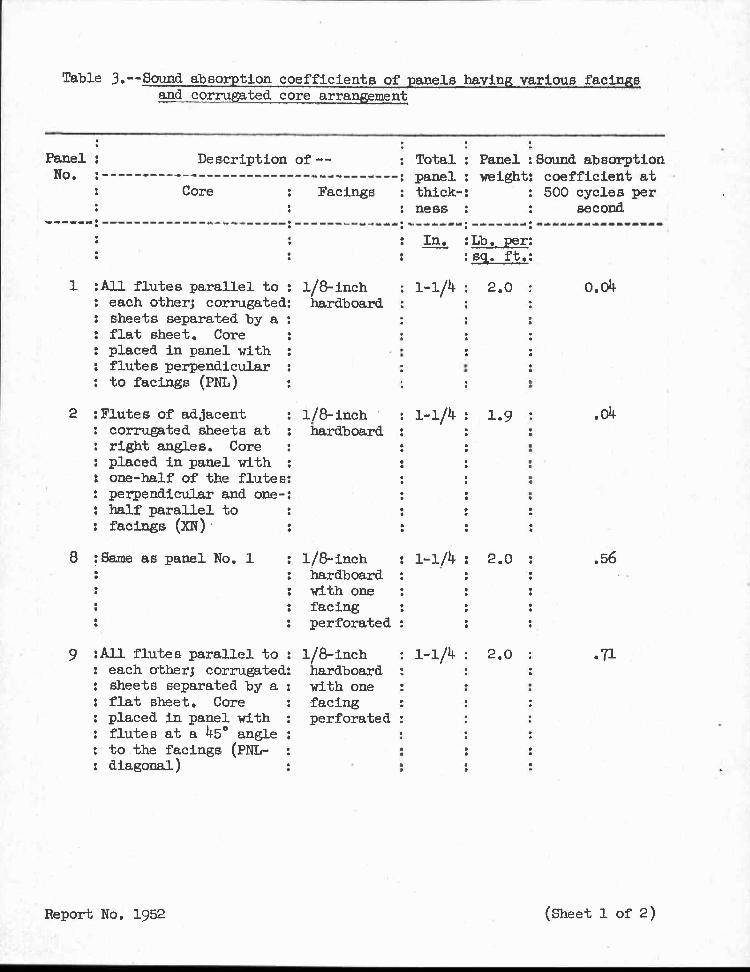
Table 3.--Sound absorption coefficients, of panels having various facingsand corrugated core arrangement
•Description of --
Core Facings
•
1 :All flutes parallel to : 1/8-inch : 1-1/4 : 2.0: each other; corrugated: hardboard :: sheets separated by a :: flat sheet. Core: placed in panel with :: flutes perpendicular :: to facings (PNL)
2 :Flutes of adjacent : 1/8-inch ' : 1-1/4 : 1.9 :: corrugated sheets at : hardboard :: right angles. Core : •
Panel :No.
•
: Total : Panel :Sound absorption: panel : weight: coefficient at
: thick-: : 500 cycles per
Hess : •• second
: In. :Lb. per::s1. ft.:
(Lott
.04•••
9 :All flutes parallel to :: each other; corrugated:: sheets separated by a :: flat sheet. Core: placed in panel with :: flutes at a 45° angle :
to the facings (PNL- :: diagonal)
••
1/8-inch : 1-1/4 2.0 : .56hardboard :with one :facingperforated :
1/8-inch : 1-1/4 2.0 : .71hardboardwith one :facingperforated :
••••
: placed in. panel with :: one-half of the flutes:: perpendicular and one-:: half parallel to: facings (XN)
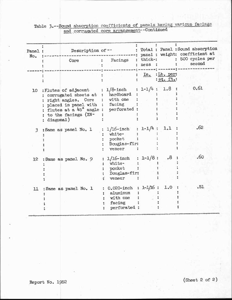
Table 3.--Sound absorption coefficients of panels having various facings and corrugated core arrangement--Continued
Total : Panel :Sound absorptionpanel : weight: coefficient atthick-: : 5001 cycles per
ness : second
Panel : Description of--
No. :
•
Core Facings :
0.6110 :Flutes of adjacent: corrugated sheets at: right angles. Core: placed in panel with: flutes at a 45° angle: to the facings (XN-: diagonal)
3 :Same as panel No. 1 .62
veneer
12 :Same as panel No. 9 : 1/16-inch: white-
; pocket: Douglas-fir:•
veneer
11 :Same as panel No. 1 : 0.020-inch :: : aluminum :•. : with one :• •: : facing .•. : perforated :
.8 :
1.0 :
.60
.51
Report No. 1952 (Sheet 2 of 2)
.vey,teelw
Ael
AIL,* ." roc-Ai -n.7 AI. 411
AR ...•
.04"*,,dapt„* ...a -JR
Figure 1. --Top, expanded type of paper honeycomb core; bottom,figure-8 type of paper honeycomb core.
Z M 93837 F
Figur e 4. --Apparatus for determining thermal conductivity: c, platescooled by running water; E, guarded hot plate; i, test samples. Thefront of the enclosure is removed.
Z M 72164 F
u) U?
up ea co cd
.--, >2>2
N Es1 ,-1 r.0 H
'Lc\ i–I 1-01 N •---1 U)
01 0 r-I li \ a) .--I,0 9:1 .-1 rd cu ,0 -El CN rri 0.)O Z ••O cd . .—I g ta g g H a3 ca cdO „0 w. • 0 0 0 04 c.) ,0 W • • 0 0 P4
>2 o .% -.-1 .-1 0 2 .. r.0 • 0 ••• •1-I ,—I q E En0) -H ni n•0 0 cua) •H al tit? • CO CA a)l-a V q ta0 0 01 • W F-t 1) 0 En
4 2g ..R44_, 0 rA
RI •0 •,-t4 g 0 ., , 4-3 c.) r-i 00 ,EJ H 4 q •,-1
cs3 rd •P-4q '171 .—I ••• •--1 -P -0 0 0 'H LID
:.j2i •0S7 > 0 o u3 •r-'11
• g 0F4 rn0.) 0 El S[; aF 0 0 al criPi l'i-i 0 I.4 0 0 0 q- Pk C-1 • rd C) • o Ea E1-4al 0 r4 4-) • ,0 u q a 0 NI 4&.)1 y-i .0 0 0
PL, Ed R4 C.) >2 -T-1 11-1 rd o •.i 4•, 7.1
0 • S-4 • • 0 -1.3 0 ai 0 • $-n ILIr
0 +' 0 04.-1 0 o .., Ca 0 0 4-) EH 0 0 • aa 0 ca 4-)O ..,1 ,.,„ ..._.-
0 .8 r'0 co 0 -,--1
4-7 +. al •—•• En 0 $.4
.0 rt.; a) 0 .—I 0 al4-3••• Eli rn 0 F-;
C) (0 9-1 0+>3.) 13 14
1-
coa) u) 1 0;•4 E4 q 4-) 5-1
-r-)' D E: 1) Pri• I-1 Ei: F.-I ;-I 0 +3 4-1-1 0 4 a) En