14 Thermal Design of Cooling and Dehumidifying Coils M. Khamis Mansour and M. Hassab Mechanical Engineering Department, Faculty of Engineering, Beirut Arab University, Lebanon 1. Introduction The cooling and dehumidifying coil is a critical component of air conditioning. Its performance has a strong bearing on the ultimate indoor environmental conditions, which in turn, has a significant impact on the indoor air quality. Decisions made to select a cooling coil influence the initial investment as well as the costs of installing, providing, and maintaining thermal comfort. The efficient thermal design of the cooling coil leads to a crucial reduction in the coil surface heat transfer area and of course, its capital cost and its weight. On the other hand, the enhancement in the coil thermal performance will usually be established at expense of the hydraulic performance of the cooling coil and in turn, its running cost. Because the cooling coil is an integral part of the air distribution system, its geometry — size, number of rows, fin spacing, and fin profile — contributes to the airside pressure drop and affects the sound power level of the fans. (Fan power needed to circulate air through the duct system may warrant extra sound attenuation at the air handler.) Cooling coils are an integral part of the chilled water system or the refrigeration unit, too. The extent to which coils raise the chilled water temperature or the evaporation temperature dramatically affects both capital investment in the cooling coil or the pumping power. Coil performance can even influence the efficiency of the chiller or Dx-unit. The focus of this chapter is on the description of the methodology should be used in thermal design of the cooling coil either chilled water coil or Dx-coil. Methods to design the cooling and dehumidifying coil either chilled water coil or Dx evaporator coil are usually based on log mean enthalpy or log equivalent dry-bulb temperature difference [1]. In both methods, the cooling coil is treated as a single zone/region and hence the required surface area is determined [2]. This manner of the cooling coil design could lead to an imprecise design particularly when the cooling coil is partially wet. In this chapter, the numerical calculation using a discrete technique "row-by- row method" will be presented to calculate the detailed design of the cooling coil in order to enhance the calculation accuracy and trace the air and coil surface temperature locally. 2. Types of cooling coils Cooling coils are classified to direct-expansion (DX) coils and chilled water coils as shown in Figure 1. Some coil manufacturers fabricate coils from 5/8 inch OD copper tubes, others www.intechopen.com
Transcript
14
Thermal Design of Cooling and Dehumidifying Coils
M. Khamis Mansour and M. Hassab Mechanical Engineering Department, Faculty of Engineering,
Beirut Arab University, Lebanon
1. Introduction
The cooling and dehumidifying coil is a critical component of air conditioning. Its performance has a strong bearing on the ultimate indoor environmental conditions, which in turn, has a significant impact on the indoor air quality. Decisions made to select a cooling coil influence the initial investment as well as the costs of installing, providing, and maintaining thermal comfort. The efficient thermal design of the cooling coil leads to a crucial reduction in the coil surface heat transfer area and of course, its capital cost and its weight. On the other hand, the enhancement in the coil thermal performance will usually be established at expense of the hydraulic performance of the cooling coil and in turn, its running cost. Because the cooling coil is an integral part of the air distribution system, its geometry — size, number of rows, fin spacing, and fin profile — contributes to the airside pressure drop and affects the sound power level of the fans. (Fan power needed to circulate air through the duct system may warrant extra sound attenuation at the air handler.) Cooling coils are an integral part of the chilled water system or the refrigeration unit, too. The extent to which coils raise the chilled water temperature or the evaporation temperature dramatically affects both capital investment in the cooling coil or the pumping power. Coil performance can even influence the efficiency of the chiller or Dx-unit. The focus of this chapter is on the description of the methodology should be used in thermal design of the cooling coil either chilled water coil or Dx-coil.
Methods to design the cooling and dehumidifying coil either chilled water coil or Dx evaporator coil are usually based on log mean enthalpy or log equivalent dry-bulb temperature difference [1]. In both methods, the cooling coil is treated as a single zone/region and hence the required surface area is determined [2]. This manner of the cooling coil design could lead to an imprecise design particularly when the cooling coil is partially wet. In this chapter, the numerical calculation using a discrete technique "row-by-row method" will be presented to calculate the detailed design of the cooling coil in order to enhance the calculation accuracy and trace the air and coil surface temperature locally.
2. Types of cooling coils
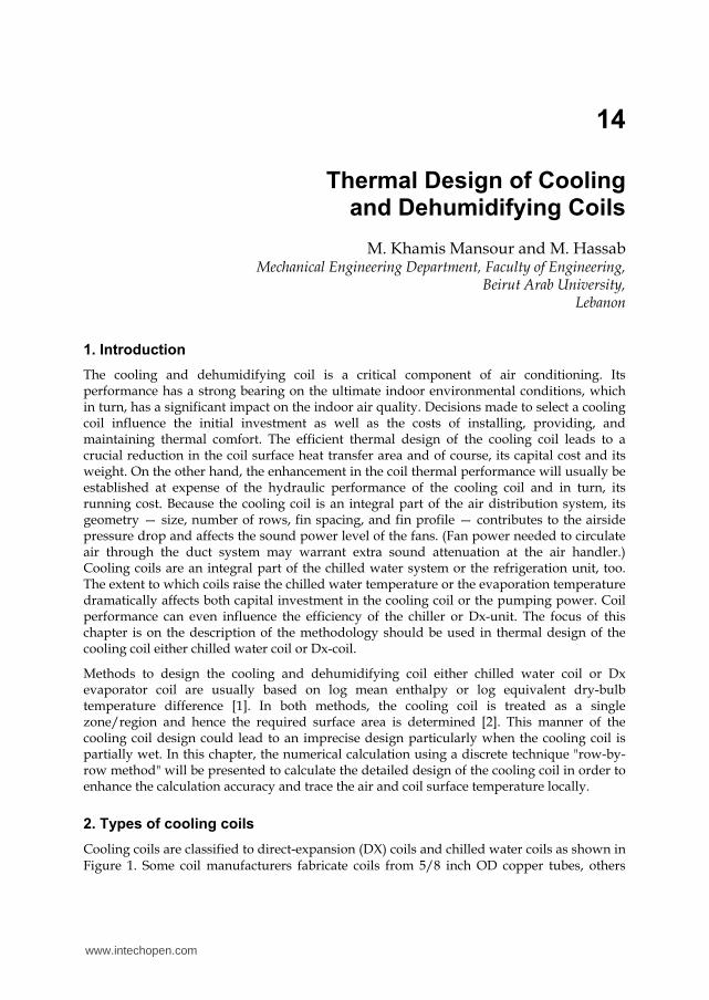
Cooling coils are classified to direct-expansion (DX) coils and chilled water coils as shown in Figure 1. Some coil manufacturers fabricate coils from 5/8 inch OD copper tubes, others
www.intechopen.com
Heat Exchangers – Basics Design Applications 368
from 1/2 inch copper tube and still others use 3/8 inch tubes. Selection of the tube size is a matter of manufacturer's choice and market demand. Price, as always, plays a major part in the tube size selection.
a) b)
Fig. 1. Description of the cooling coil for a)- Dx-cooling; b)- Chilled water coil (Aerofin heat transfer products).
3. Coil construction and geometry
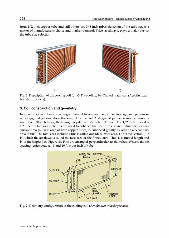
In a coil, copper tubes are arranged parallel to one another, either in staggered pattern or non-staggered pattern, along the length L of the coil. A staggered pattern is more commonly used. For 5/8 inch tubes, the triangular pitch is 1.75 inch or 1.5 inch. For 1/2 inch tubes it is 1.25 inch. Plate or ripple fins are used to enhance the heat transfer area. Thus the primary surface area (outside area of bare copper tubes) is enhanced greatly by adding a secondary area of fins. The total area including fins is called outside surface area. The cross-section (L × H) which the air flows is called the face area or the finned area. Thus L is finned length and H is fin height (see Figure 2). Fins are arranged perpendicular to the tubes. Where, the fin spacing varies between 8 and 16 fins per inch of tube.
Fig. 2. Geometry configuration of the cooling coil (Aerofin heat transfer products).
www.intechopen.com
Thermal Design of Cooling and Dehumidifying Coils 369
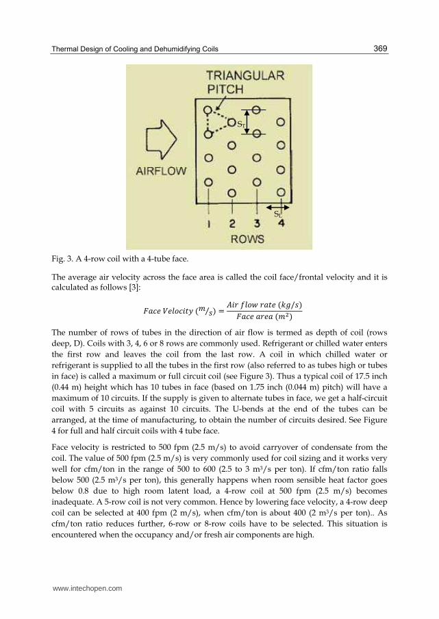
Fig. 3. A 4-row coil with a 4-tube face.
The average air velocity across the face area is called the coil face/frontal velocity and it is calculated as follows [3]:
The number of rows of tubes in the direction of air flow is termed as depth of coil (rows
deep, D). Coils with 3, 4, 6 or 8 rows are commonly used. Refrigerant or chilled water enters
the first row and leaves the coil from the last row. A coil in which chilled water or
refrigerant is supplied to all the tubes in the first row (also referred to as tubes high or tubes
in face) is called a maximum or full circuit coil (see Figure 3). Thus a typical coil of 17.5 inch
(0.44 m) height which has 10 tubes in face (based on 1.75 inch (0.044 m) pitch) will have a
maximum of 10 circuits. If the supply is given to alternate tubes in face, we get a half-circuit
coil with 5 circuits as against 10 circuits. The U-bends at the end of the tubes can be
arranged, at the time of manufacturing, to obtain the number of circuits desired. See Figure
4 for full and half circuit coils with 4 tube face.
Face velocity is restricted to 500 fpm (2.5 m/s) to avoid carryover of condensate from the
coil. The value of 500 fpm (2.5 m/s) is very commonly used for coil sizing and it works very
well for cfm/ton in the range of 500 to 600 (2.5 to 3 m3/s per ton). If cfm/ton ratio falls
below 500 (2.5 m3/s per ton), this generally happens when room sensible heat factor goes
below 0.8 due to high room latent load, a 4-row coil at 500 fpm (2.5 m/s) becomes
inadequate. A 5-row coil is not very common. Hence by lowering face velocity, a 4-row deep
coil can be selected at 400 fpm (2 m/s), when cfm/ton is about 400 (2 m3/s per ton).. As
cfm/ton ratio reduces further, 6-row or 8-row coils have to be selected. This situation is
encountered when the occupancy and/or fresh air components are high.
SL
ST
www.intechopen.com
Heat Exchangers – Basics Design Applications 370
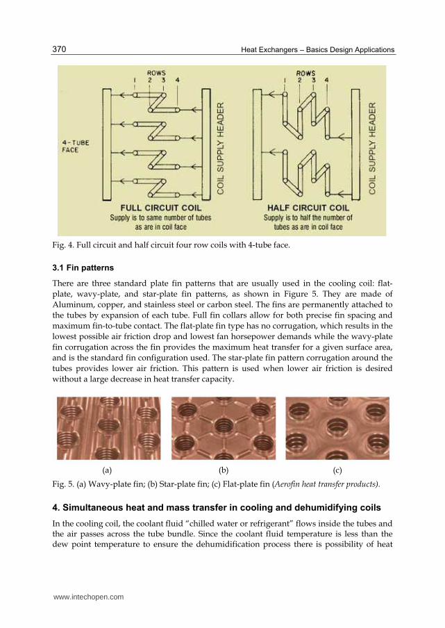
Fig. 4. Full circuit and half circuit four row coils with 4-tube face.
3.1 Fin patterns
There are three standard plate fin patterns that are usually used in the cooling coil: flat-
plate, wavy-plate, and star-plate fin patterns, as shown in Figure 5. They are made of
Aluminum, copper, and stainless steel or carbon steel. The fins are permanently attached to
the tubes by expansion of each tube. Full fin collars allow for both precise fin spacing and
maximum fin-to-tube contact. The flat-plate fin type has no corrugation, which results in the
lowest possible air friction drop and lowest fan horsepower demands while the wavy-plate
fin corrugation across the fin provides the maximum heat transfer for a given surface area,
and is the standard fin configuration used. The star-plate fin pattern corrugation around the
tubes provides lower air friction. This pattern is used when lower air friction is desired
without a large decrease in heat transfer capacity.
(a) (b) (c)
Fig. 5. (a) Wavy-plate fin; (b) Star-plate fin; (c) Flat-plate fin (Aerofin heat transfer products).
4. Simultaneous heat and mass transfer in cooling and dehumidifying coils
In the cooling coil, the coolant fluid “chilled water or refrigerant” flows inside the tubes and the air passes across the tube bundle. Since the coolant fluid temperature is less than the dew point temperature to ensure the dehumidification process there is possibility of heat
www.intechopen.com
Thermal Design of Cooling and Dehumidifying Coils 371
and moisture transfer between them. The directions of heat and moisture transfer depend upon the temperature and vapor pressure differences between air and wetted surface. As a result, the direction of the total heat transfer rate, which is a sum of sensible heat transfer and latent heat transfers. The concept of enthalpy potential [4] is very useful in quantifying the total heat transfer in these processes and its direction.
The sensible (QS) and latent (QL) heat transfer rates are given by:
QS = ho AS (ti – ta)
QL = hmass AS (Wi – Wa) hfg
the total heat transfer QT is given by:
QT = QS +QL = ho AS (ti – ta) + hmass As (Wi – Wa) hfg
Where:
t a = dry-bulb temperature of air, oC t i= temperature of water/wetted surface, oC Wa = humidity ratio of air, kg/kg Wi= humidity ratio of saturated air at ti, kg/kg ho = convective heat transfer coefficient, W/m2.oC hmass = convective mass transfer coefficient, kg/m2 hfg = latent heat of vaporization, J/kg
Since the transport mechanism that controls the convective heat transfer between air and water also controls the moisture transfer between air and water, there exists a relation between heat and mass transfer coefficients, hC and hD as discussed in an earlier chapter. It has been shown that for air-water vapor mixtures,
Hmass≈ho/cpm or ho/hmass.cpm = Lewis number ≈ 1.0
Where cpm is the humid air specific heat ≈ 1.0216 kJ/kg.K. Hence the total heat transfer is given by:
QT = QS +QL = ho AS (ti – ta) + hmass AS (Wi – Wa) hfg = (ho AS/Cpm )[(ti – ta) +(Wi – Wa) hfg]
by manipulating the term in the parenthesis of RHS, it can be shown that:
QT = QS +QL = (ho AS/cpm )[ (hi – ha)]
The air heat transfer coefficient, ho has been computed from the experimental correlations derived in [3]. The heat transfer parameter is written as Stanton number, St times Prandtl number, Pr to the 2/3 power. It is given as a function of Reynolds number, Re where the function was established through curve-fitting of a set of the experimental data as follow: 鯨建 × 鶏堅岫態/戴岻 = ど.ななにぬ × 迎結貸待.態滞怠 Where these three dimensionless parameters are defined as:
St = 岫A鱈辿樽xh誰岻盤m叩 × c丹鱈匪, Pr = 盤μ叩 × c丹鱈匪k叩 , andRe = 岫m叩 × d誰岻岫A鱈辿樽xμ叩岻
www.intechopen.com
Heat Exchangers – Basics Design Applications 372
Where, A鱈辿樽 = minimum free-flow air area, (m2) m叩 = mass flow rate of air through the cooling coil, (kg/s) μ叩 =dynamic viscosity of air (kg/m.s) k叩 =thermal conductivity of air (W/m. °C) d誰 =outside diameter, (m)
5. Governing equations and methodology
The sizing of cooling coil requires solving the two energy equations of the air-side and
coolant sides coupling with the heat and mass transfer equations. The design is
accomplished through discretizing the cooling coil into N segments according to the number
of the coil rows. The three governing equations are applied to each segment. By knowing the
process data, coil geometry, and the design cooling load imposed on the coil the required
surface area can be computed. The coil sizing is expressed by the face area and number of
rows of a finned-tube coil for satisfying the design coil cooling load.
Process data:
- Room dB temperature/Return air dB temperature (°C) - Fresh air dB temperature (°C) - Dehumidified air flow (cfm or m3/s) - Fresh air quantity (cfm or m3/s) - Grand sensible heat factor (GSHF) - Coil cooling load (kW) - Apparatus dew point ADP (°C) (This denotes the average outside surface temperature
of the coil.)
Coil geometry :
- Outside tube diameter, do (mm) - Inside tube diameter, di (mm) - Longitudinal tube spacing, SL (mm) (see Figure 3) - Transverse tube spacing, ST (mm) (see Figure 3) - No. of fins/m, Nf - Aluminum fin thickness, tf (mm) - Exchanger compactness, surface area over exchanger volume, β (m2/m3)
Air-Side
∆Q達辿 = m叩岫ha辿 − ha辿袋怠岻 (1)
∆Q達辿 = 遅棟達東悼 h誰ΔA誰岫ha鱈辿 − hs鱈辿岻 (2)
Water-Side
∆Q達辿 = m歎Cp歎岫Tw辿袋怠 − Tw辿岻 (3)
ΔQ達辿 = h辿ΔA辿岫Ts鱈辿 − Tw鱈辿岻 (4)
www.intechopen.com
Thermal Design of Cooling and Dehumidifying Coils 373
Here,
ha鱈辿 = 岫竪叩套袋竪叩套甜迭岻態 , ha辿袋怠 = にha鱈辿 − ha辿 (5)
Tw鱈辿 = 岫鐸歎套袋鐸歎套甜迭岻態 , Tw辿袋怠 = にTw鱈辿 − Tw辿 (6)
Eliminate hai+1 and Twi+1 from Equation (1) & (3) respectively, the energy equations can be
formulated;
∆Q達辿 = にm叩岫ha辿 − ha鱈辿岻 (7)
∆Q達辿 = にm歎Cp歎岫Tw鱈辿 − Tw辿岻 (8)
Eliminate ha鱈辿between equations (2) & (7), it is yielded:
∆Q達辿 = 遅棟竪搭綻代搭/達東悼怠袋綻択鐸濁搭/態 ∗ 岫ha辿 − hs鱈辿岻 (9)
Similarly, eliminate Tw鱈辿between equations (4) and (8):
∆Q達辿 = 竪套綻代套怠袋綻択鐸濁套/態 ∗ 岫Ts鱈辿 − Tw辿岻 (10)
Now, by dividing equation (9) over equation (10):
竪叩套貸竪坦悼套鐸坦悼套貸鐸歎套 = R (11)
Where,
R = 峙竪套達東悼竪搭遅棟 岾∆代套∆代搭峇峩 ∗ 峪岾怠袋答登砥砺搭鉄 峇岾怠袋答登砥砺套鉄 峇崋 (12)
ΔNTU誰 = 遅棟竪搭綻代搭鱈倒達東悼 ,ΔNTU辿 = 竪套綻代套鱈涛大丹涛
Relation between hs and Ts:
a. Dry-Surface (Ts Tdew point)
hs鱈辿= ha + c丹 (Ts鱈辿-Ta) (13)
b. Wet-Surface ( Ts Tdew point)
When the coil is wet the enthalpy of saturated air hs鱈辿is a function of the temperature of the
wetted surface Ts鱈辿, by curve fitting for psychometric chart [2] of the saturated air enthalpy
at different air temperatures of a range 3 to 11oC. The quadric equation is expressed as :
hs鱈辿 = など.ばは + な.ねTs鱈辿 + ど.どねはTs鱈辿態 (14)
Solution for Ts鱈辿: Substituting for hs鱈辿 from equations (14) into equation (11), we obtain a solution for Ts鱈辿 as
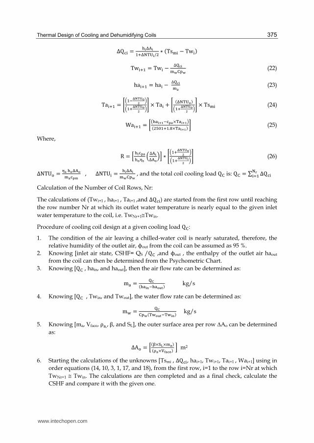
The final solutions for the coil capacity per row and for the states of air and water at the exit of any row within a chilled-water coil are given, in terms of the mean outer surface temperature of this row, as:
R = 峙竪套達東倒竪搭遅棟 岾∆代套∆代搭峇峩 ∗ 峪岾怠袋答登砥砺搭鉄 峇岾怠袋答登砥砺套鉄 峇崋 (26)
ΔNTU誰 = 遅棟竪搭綻代搭鱈倒達東悼 ,ΔNTU辿 = 竪套綻代套鱈涛大丹涛 , and the total coil cooling load Q大 is: Q大 = ∑ ∆Q達辿択梼辿退怠
Calculation of the Number of Coil Rows, Nr:
The calculations of (Twi+1 , hai+1 , Tai+1 ,and ∆Q達辿) are started from the first row until reaching
the row number Nr at which its outlet water temperature is nearly equal to the given inlet
water temperature to the coil, i.e. TwNr+1Twin.
Procedure of cooling coil design at a given cooling load Q大:
1. The condition of the air leaving a chilled-water coil is nearly saturated, therefore, the
relative humidity of the outlet air, ϕout from the coil can be assumed as 95 %.
2. Knowing [inlet air state, CSHF= QS /Q大 ,and ϕout , the enthalpy of the outlet air haout
from the coil can then be determined from the Psychometric Chart.
3. Knowing [Q大 , hain, and haout], then the air flow rate can be determined as: m叩 = 濯電岫竪叩套投貸竪叩搭淘盗岻 kg/s
4. Knowing [Q大 , Twin, and Twout], the water flow rate can be determined as: m歎 = 濯電大丹涛岫鐸歎搭淘盗貸鐸歎套投岻 kg/s
5. Knowing [ma, Vface, ρ叩,,β, and SL], the outer surface area per row ∆Ao can be determined
as: ΔA誰 = 峙岫痴×託杜×鱈倒岻岫茶倒×諾唐倒冬刀岻 峩 m2
6. Starting the calculations of the unknowns [Tsmi , ∆Q達辿, hai+1, Twi+1, Tai+1 , Wai+1] using in
order equations (14, 10, 3, 1, 17, and 18), from the first row, i=1 to the row i=Nr at which
TwNr+1 Twin. The calculations are then completed and as a final check, calculate the
CSHF and compare it with the given one.
www.intechopen.com
Heat Exchangers – Basics Design Applications 376
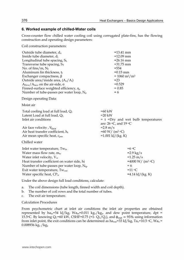
6. Worked example of chilled-Water coils
Cross-counter flow chilled water cooling coil using corrugated plate-fins, has the flowing construction and operating design parameters:
Coil construction parameters:
Outside tube diameter, do =13.41 mmInside tube diameter, di =12.09 mmLongitudinal tube spacing, SL =26.16 mmTransverse tube spacing, ST =31.75 mmNo. of fins/m, Nf =554Aluminum fin thickness, tf =0.15 mmExchanger compactness, β = 1060 m2/m3
Outside area/inside area, (Ao/Ai) =23Aflow/Aface on the air-side, =0.529Finned-surface weighted efficiency, 考鎚 = 0.85Number of tube-passes per water loop, Np = 6
Design operating Data:
Moist air
Total cooling load at full load, Qc =60 kWLatent Load at full load, QL =20 kWInlet air conditions = t =Dry and wet bulb temperatures
are: 26 oC, and 19 oC Air face velocity , V脱叩達奪 =2.8 m/sAir heat transfer coefficient, hc =60 W/ (m2 oC) Air mean specific heat, cpm =1.001 kJ/(kg. K)
Chilled water
Inlet water temperature, Twin Water mass flow rate, mw Water inlet velocity, Vw
=6 oC =2.9 kg/s =1.25 m/s
Heat transfer coefficient on water side, hi =4000 W/ (m2 oC) Number of tube-passes per water loop, Ntp Exit water temperature, Twout
Water specific heat, CPw
= 6 =11 oC =4.14 kJ/(kg. K)
Under the above design full load conditions, calculate:
a. The coil dimensions (tube length, finned width and coil depth). b. The number of coil rows and the total number of tubes. c. The exit air temperature.
Calculation Procedures
From psychometric chart at inlet air conditions the inlet air properties are obtained represented by hain=54 kJ/kg, Wain=0.011 kgv/kga. and dew point temperature, dpt = 15.5oC. By knowing QC=60 kW, CSHF=0.75 (=1- QL/Qc), andϕ誰探担 = ひの% using information from inlet point, the exit conditions can be determined as haout=33 kJ/kg, Tao=10.5 oC, Wao = 0.008936 kgv /kga
www.intechopen.com
Thermal Design of Cooling and Dehumidifying Coils 377
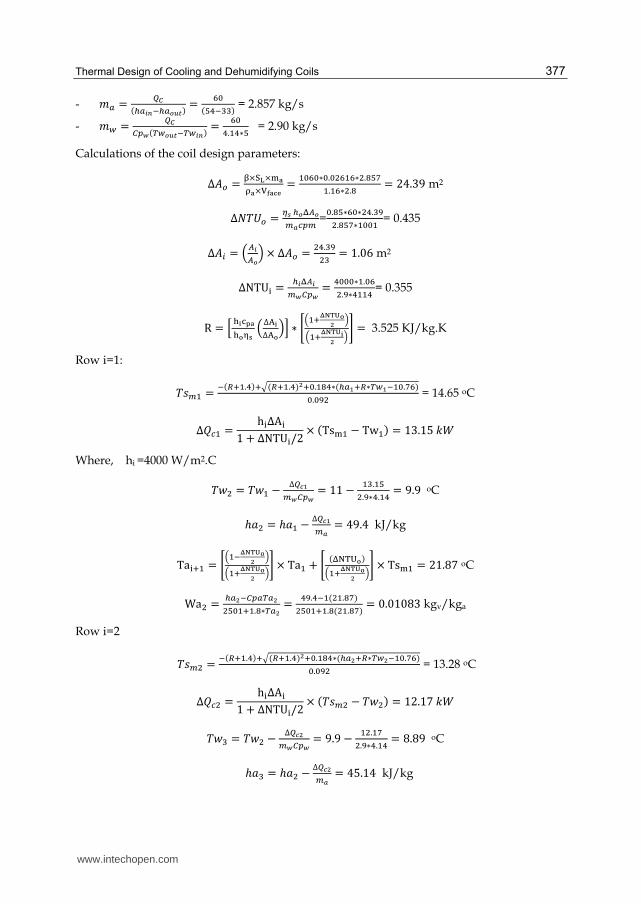
- 兼銚 = 町頓岫朕銚日韮貸朕銚任祢禰岻 = 滞待岫泰替貸戴戴岻 = 2.857 kg/s
- 兼栂 = 町頓寵椎葱岫脹栂任祢禰貸脹栂日韮岻 = 滞待替.怠替∗泰 = 2.90 kg/s
Calculations of the coil design parameters: Δ畦墜 = 痴×託杜×鱈倒茶倒×諾唐倒冬刀 = 怠待滞待∗待.待態滞怠滞∗態.腿泰胎怠.怠滞∗態.腿 = にね.ぬひ m2
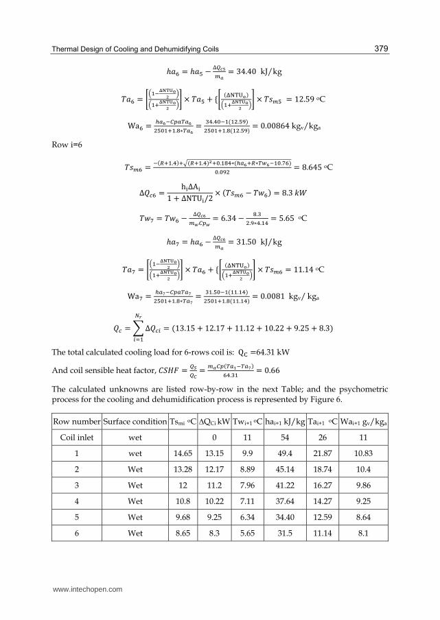
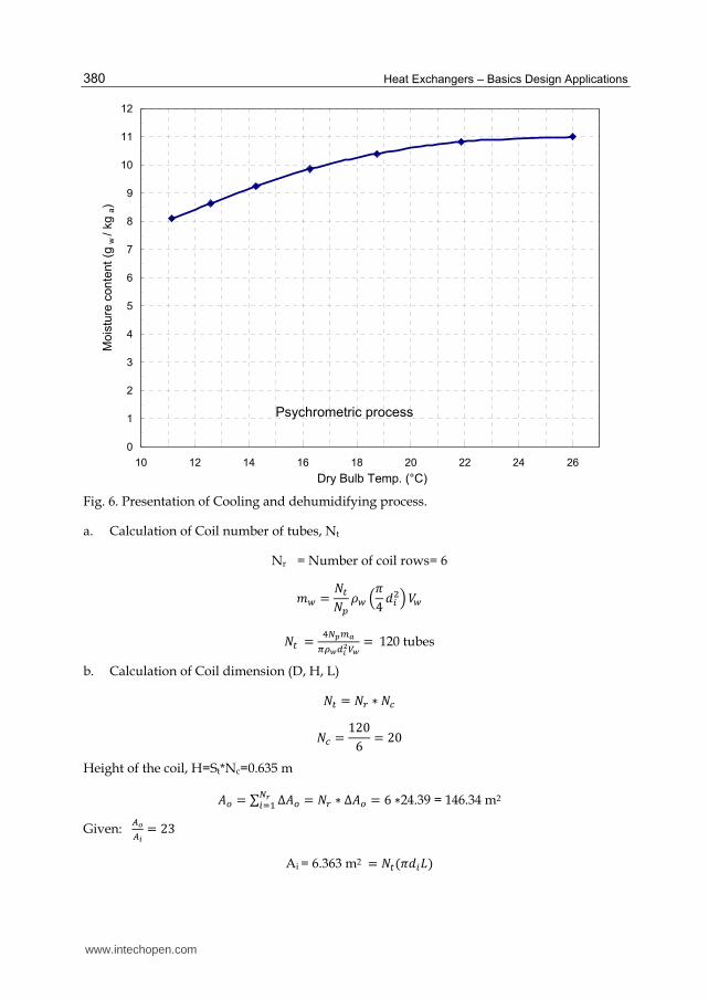
The calculated unknowns are listed row-by-row in the next Table; and the psychometric process for the cooling and dehumidification process is represented by Figure 6.
Fig. 6. Presentation of Cooling and dehumidifying process.
a. Calculation of Coil number of tubes, Nt
Nr = Number of coil rows= 6
兼栂 = 軽痛軽椎 貢栂 岾講ね 穴沈態峇撃栂
軽痛 = 替朝妊陳尼訂諦葱鳥日鉄蝶葱 = 120 tubes
b. Calculation of Coil dimension (D, H, L) 軽痛 = 軽追 ∗ 軽頂 軽頂 = なにどは = にど
Height of the coil, H=St*Nc=0.635 m 畦墜 = ∑ Δ畦墜朝認沈退怠 = 軽追 ∗ Δ畦墜 = は ∗24.39 = 146.34 m2
Given: 凋任凋日 = にぬ
Ai = 6.363 m2 = 軽痛岫講穴沈詣岻
Psychrometric process
0
1
2
3
4
5
6
7
8
9
10
11
12
10 12 14 16 18 20 22 24 26
Dry Bulb Temp. (°C)
Mois
ture
con
tent
(g w
/ kg a
)
www.intechopen.com
Thermal Design of Cooling and Dehumidifying Coils 381
詣 = 詣結券訣建ℎ剣血建ℎ結潔剣件健 = 畦沈講軽痛穴沈 = な.ね兼
経 = 系剣件健穴結喧建ℎ = 軽頂 ∗ 鯨挑 = ど.なのば兼
c. Exit air temperature
Taout=11.14 oC
Design of the cooling coil as single Region
In calculating the surface area of the cooling coil, the heat and mass transfer equations are applied on the entire coil surface. This approximation will greatly simplify the analysis. The obtained results ( Ao, Taout) for one-section coil will be compared with the corresponding results obtained for Nr-sections coil.
Air-side
芸頂 = 兼銚岫ℎ欠怠 − ℎ欠態岻 (1)
芸頂 = 挺濡頂妊 ℎ墜畦墜岫ℎ欠陳 − ℎ嫌陳岻 (2)
Water-side
芸頂 = 兼栂系喧栂岫劇拳態 − 劇拳怠岻 (3)
芸頂 = ℎ沈畦沈岫劇嫌陳 − 劇拳陳岻 (4)
Applying the heat transfer equations for the air and water at the inlet and exit sections of the coil, this leads to the following equation for Ts at these sections:
R = 竪叩迭貸竪坦迭鐸坦迭貸鐸歎迭 = 竪叩鉄貸竪坦鉄鐸坦鉄貸鐸歎鉄 (5)
For an entire wet-surface, the saturated air temperature at the inlet and exit of the coil surfaces Ts1 and Ts2 are obtained, in a similar manner as done before for N-sections coil, as:
Knowing (Ts1 & Tw1) and (Ts2 & Tw2), the mean temperature difference between the chilled water and the coil surface can be assumed equal to the logarithmic mean temperature difference. ∆劇陳 can be determined from:
The area of the coil can now be determined from equation (4) as:
畦沈 = 町頓朕日∗∆脹尿 (10)
The outer coil surface area Ao is determined from
畦墜 = 岾凋任凋日峇畦沈 (11)
The volume of the cooling coil is given as:
Volume = DHL
DHL =紅畦墜 (12)
Number of Coil Tubes Nt:
兼栂 = 朝禰朝妊 貢栂 岾訂替 穴沈態峇 撃栂
軽痛 = 替朝妊陳尼訂諦葱鳥日鉄蝶葱 (13)
The Length of the Tube (Coil), L:
詣 = 凋日朝禰訂鳥日 (14)
The Coil Face Area, Aface:
畦捗銚頂勅 = 茎詣 = 陳尼諦尼蝶肉尼迩賑 (15)
From Equations (14) and (15) H can be determined as:
茎 = 磐 陳尼諦尼蝶肉尼迩賑卑 ∗ 岾朝禰訂鳥日凋日 峇 (16)
Number of Rows, Nr:
軽追 = 調聴畷 (17)
Depth of the Coil D:
経 = 軽追 ∗ 鯨挑 (18)
Calculation of exit air Temperature:
The temperature difference between the air stream and the coil surface is approximated as arithmetic mean temperature difference as shown from the heat transfer equation for the dry air.
芸鎚 = 兼銚系喧銚岫劇欠怠 − 劇欠態岻 (19)
www.intechopen.com
Thermal Design of Cooling and Dehumidifying Coils 383
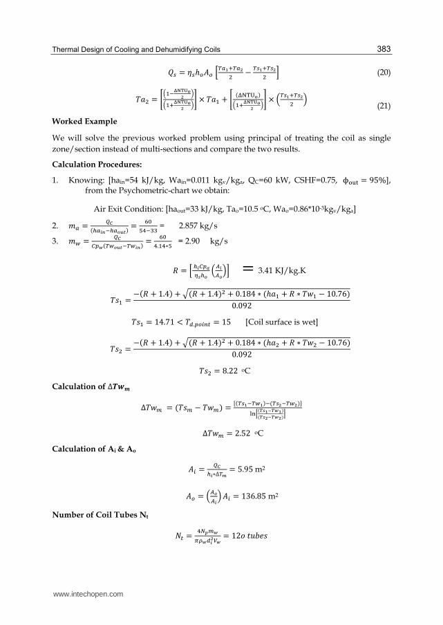
Calculation of Latent load and CSHF 芸挑芸聴 = はど − に.ぱのば ∗ 岫には − など.ひの岻 = なば倦激倦激
系鯨茎繋 = はど − なばはど = ど.ばなば
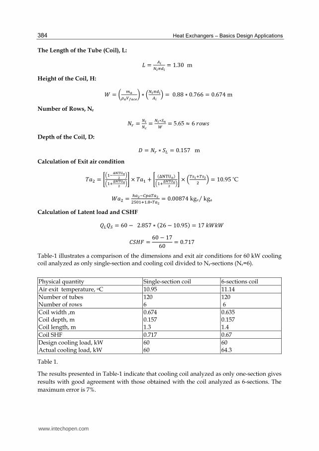
Table-1 illustrates a comparison of the dimensions and exit air conditions for 60 kW cooling coil analyzed as only single-section and cooling coil divided to Nr-sections (Nr=6).
The results presented in Table-1 indicate that cooling coil analyzed as only one-section gives
results with good agreement with those obtained with the coil analyzed as 6-sections. The
maximum error is 7%.
www.intechopen.com
Thermal Design of Cooling and Dehumidifying Coils 385
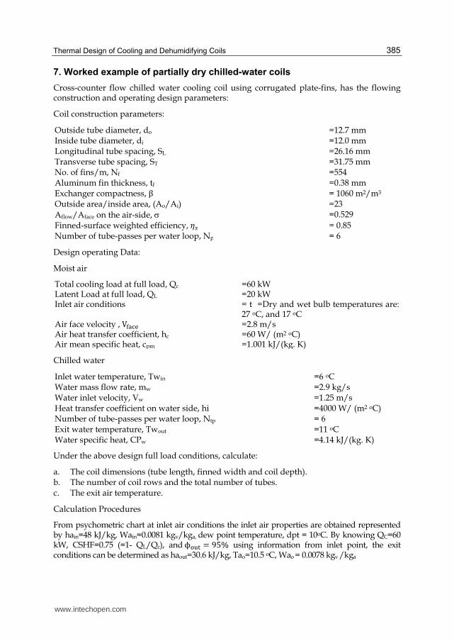
7. Worked example of partially dry chilled-water coils
Cross-counter flow chilled water cooling coil using corrugated plate-fins, has the flowing construction and operating design parameters:
Coil construction parameters:
Outside tube diameter, do =12.7 mm Inside tube diameter, di =12.0 mm Longitudinal tube spacing, SL =26.16 mm Transverse tube spacing, ST =31.75 mm No. of fins/m, Nf =554 Aluminum fin thickness, tf =0.38 mm Exchanger compactness, β = 1060 m2/m3 Outside area/inside area, (Ao/Ai) =23
Aflow/Aface on the air-side, =0.529
Finned-surface weighted efficiency, 考鎚 = 0.85 Number of tube-passes per water loop, Np = 6
Design operating Data:
Moist air
Total cooling load at full load, Qc =60 kWLatent Load at full load, QL =20 kWInlet air conditions = t =Dry and wet bulb temperatures are:
27 oC, and 17 oC Air face velocity , V脱叩達奪 =2.8 m/sAir heat transfer coefficient, hc =60 W/ (m2 oC) Air mean specific heat, cpm =1.001 kJ/(kg. K)
Chilled water
Inlet water temperature, Twin Water mass flow rate, mw Water inlet velocity, Vw
=6 oC =2.9 kg/s =1.25 m/s
Heat transfer coefficient on water side, hi =4000 W/ (m2 oC) Number of tube-passes per water loop, Ntp Exit water temperature, Twout
Water specific heat, CPw
= 6 =11 oC =4.14 kJ/(kg. K)
Under the above design full load conditions, calculate:
a. The coil dimensions (tube length, finned width and coil depth). b. The number of coil rows and the total number of tubes. c. The exit air temperature.
Calculation Procedures
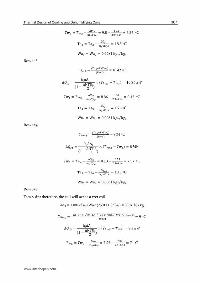
From psychometric chart at inlet air conditions the inlet air properties are obtained represented by hain=48 kJ/kg, Wain=0.0081 kgv/kga, dew point temperature, dpt = 10oC. By knowing QC=60 kW, CSHF=0.75 (=1- QL/Qc), andϕ誰探担 = ひの% using information from inlet point, the exit conditions can be determined as haout=30.6 kJ/kg, Tao=10.5 oC, Wao = 0.0078 kgv /kga
www.intechopen.com
Heat Exchangers – Basics Design Applications 386
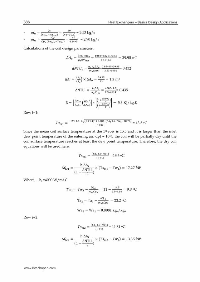
- 兼銚 = 町頓岫朕銚日韮貸朕銚任祢禰岻 = 滞待岫替腿貸戴待.滞岻 = 3.53 kg/s
- 兼栂 = 町頓寵椎葱岫脹栂任祢禰貸脹栂日韮岻 = 滞待替.怠替∗泰 = 2.90 kg/s
Calculations of the coil design parameters: Δ畦墜 = 痴×託杜×鱈倒茶倒×諾唐倒冬刀 = 怠待滞待∗待.待態滞怠∗戴.泰戴怠.怠滞∗態.腿 = にひ.ひの m2
Treating the cooling coil as a single zone "Worked Example"
We will solve the previous worked problem using principal treating the coil as single zone/section instead of multi-sections and compare the two results.
Calculation Procedures:
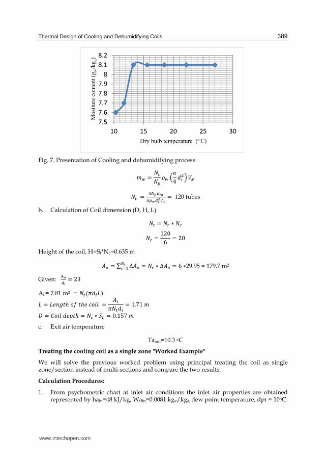
1. From psychometric chart at inlet air conditions the inlet air properties are obtained represented by hain=48 kJ/kg, Wain=0.0081 kgv/kga, dew point temperature, dpt = 10oC.
7.5
7.6
7.7
7.8
7.9
8
8.1
8.2
10 15 20 25 30
Mo
situ
re c
on
ten
t (g
w/k
ga)
Dry bulb temperature (o C)
www.intechopen.com
Heat Exchangers – Basics Design Applications 390
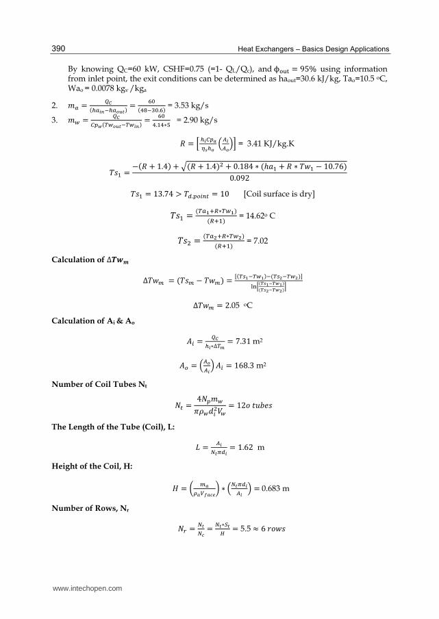
By knowing QC=60 kW, CSHF=0.75 (=1- QL/Qc), andϕ誰探担 = ひの% using information from inlet point, the exit conditions can be determined as haout=30.6 kJ/kg, Tao=10.5 oC, Wao = 0.0078 kgv /kga
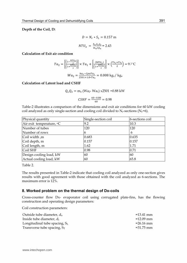
Calculation of Latent load and CSHF 芸挑芸聴 = ma (Wa2- Wa1) x2501 =0.88 kW 系鯨茎繋 = 滞待貸待.腿腿滞待 = ど.98
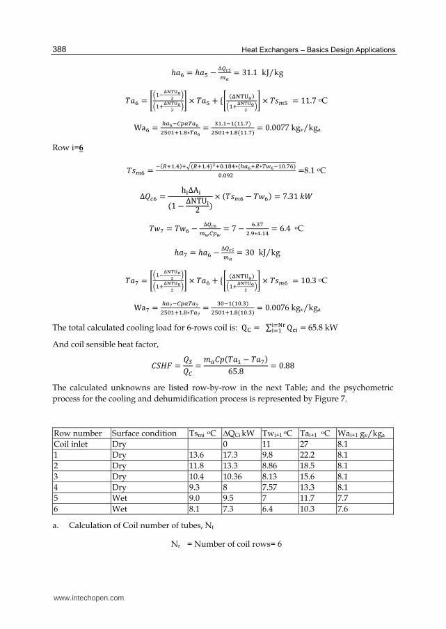
Table-2 illustrates a comparison of the dimensions and exit air conditions for 60 kW cooling coil analyzed as only single-section and cooling coil divided to Nr-sections (Nr=6).
The results presented in Table-2 indicate that cooling coil analyzed as only one-section gives results with good agreement with those obtained with the coil analyzed as 6-sections. The maximum error is 12%.
8. Worked problem on the thermal design of Dx-coils
Cross-counter flow Dx- evaporator coil using corrugated plate-fins, has the flowing construction and operating design parameters:
Coil construction parameters:
Outside tube diameter, do =13.41 mm Inside tube diameter, di =12.09 mm Longitudinal tube spacing, SL =26.16 mm Transverse tube spacing, ST =31.75 mm
www.intechopen.com
Heat Exchangers – Basics Design Applications 392
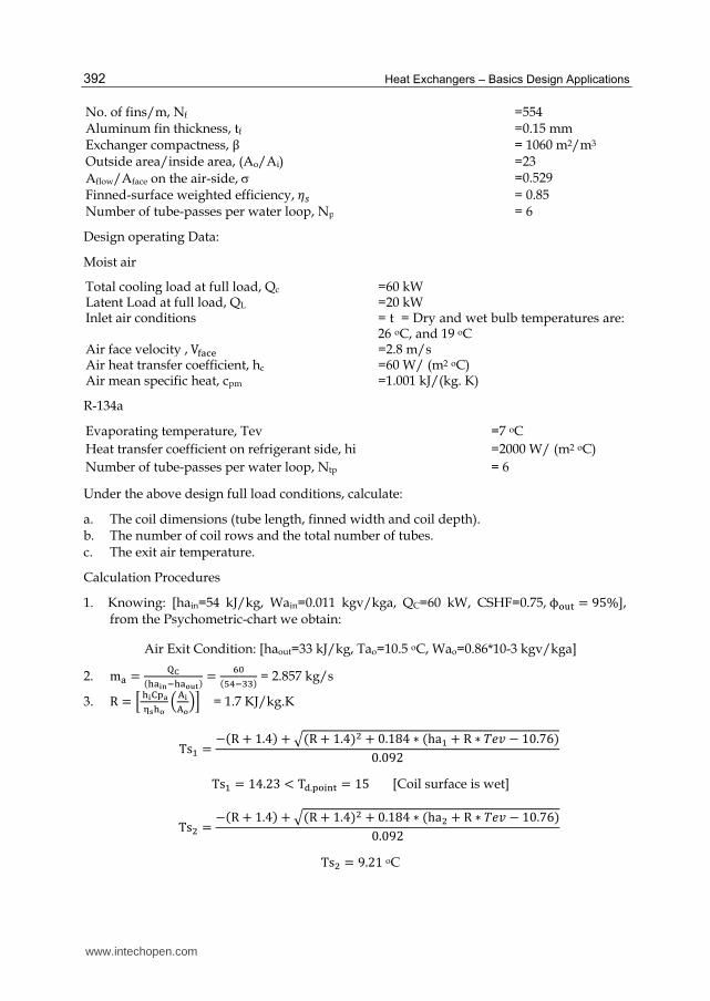
No. of fins/m, Nf =554 Aluminum fin thickness, tf =0.15 mm Exchanger compactness, β = 1060 m2/m3 Outside area/inside area, (Ao/Ai) =23
Aflow/Aface on the air-side, =0.529
Finned-surface weighted efficiency, 考鎚 = 0.85 Number of tube-passes per water loop, Np = 6
Design operating Data:
Moist air
Total cooling load at full load, Qc =60 kWLatent Load at full load, QL =20 kWInlet air conditions = t = Dry and wet bulb temperatures are:
26 oC, and 19 oC Air face velocity , V脱叩達奪 =2.8 m/sAir heat transfer coefficient, hc =60 W/ (m2 oC) Air mean specific heat, cpm =1.001 kJ/(kg. K)
R-134a
Evaporating temperature, Tev =7 oC
Heat transfer coefficient on refrigerant side, hi =2000 W/ (m2 oC)
Number of tube-passes per water loop, Ntp = 6
Under the above design full load conditions, calculate:
a. The coil dimensions (tube length, finned width and coil depth). b. The number of coil rows and the total number of tubes. c. The exit air temperature.
Calculation Procedures
1. Knowing: [hain=54 kJ/kg, Wain=0.011 kgv/kga, QC=60 kW, CSHF=0.75,ϕ誰探担 = ひの%], from the Psychometric-chart we obtain:
Air Exit Condition: [haout=33 kJ/kg, Tao=10.5 oC, Wao=0.86*10-3 kgv/kga]
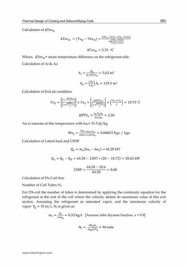
For DX-coil the number of tubes is determined by applying the continuity equation for the
refrigerant at the exit of the coil where the velocity attains its maximum value at this exit
section. Assuming the refrigerant as saturated vapor, and the maximum velocity of
vaporV巽 ≈ 10 m/s, Nt is given as: m嘆 = 濯電淡∗竪唐塔 = ど.ぬぬkg/s [Assume inlet dryness fraction, x = 0.9]
N担 = 替択東鱈梼窒茶塔辰套鉄諾塔 ≈ ひはtube
www.intechopen.com
Heat Exchangers – Basics Design Applications 394
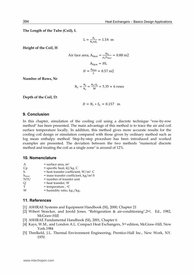
The Length of the Tube (Coil), L L = 代套択盗窒辰套 = な.のね m
Height of the Coil, H
Air face area, A脱叩達奪 = 鱈倒茶倒諾唐倒冬刀 = ど.ぱぱm2 A脱叩達奪 = 茎L 茎 =
代唐倒冬刀宅 = ど.のばm2
Number of Rows, Nr N嘆 = 択盗択冬 = 択盗∗託盗茸 = 5.35 ≈ はrows Depth of the Coil, D:
経 = 軽追 ∗ 鯨挑 = ど.なのば m
9. Conclusion
In this chapter, simulation of the cooling coil using a discrete technique "row-by-row method" has been presented. The main advantage of this method is to trace the air and coil surface temperature locally. In addition, this method gives more accurate results for the cooling coil design or simulation compared with those given by ordinary method such as log mean enthalpy method. Step-by-step procedure has been introduced and worked examples are presented. The deviation between the two methods "numerical discrete method and treating the coil as a single zone" is around of 12%.
10. Nomenclature
A = surface area, m2
Cp = specific heat, kJ/kg. Ch = heat transfer coefficient, W/m2. Chmass = mass transfer coefficient, kg/m2.S NTU = number of transfer unitQ = heat transfer, W T = temperature , oCW = humidity ratio, kgv/kga
11. References
[1] ASHRAE Systems and Equipment Handbook (SI), 2000, Chapter 21 [2] Wibert Stoecker, and Jerold Jones. "Refrigeration & air-conditioning",2nd, Ed., 1982,
McGraw-Hill [3] ASHRAE Fundamental Handbook (SI), 2001, Chapter 6 [4] Kays, W.M., and London A.L. Compact Heat Exchangers, 3rd edition, McGraw-Hill, New
InTech ChinaUnit 405, Office Block, Hotel Equatorial Shanghai No.65, Yan An Road (West), Shanghai, 200040, China
Phone: +86-21-62489820 Fax: +86-21-62489821
Selecting and bringing together matter provided by specialists, this project offers comprehensive informationon particular cases of heat exchangers. The selection was guided by actual and future demands of appliedresearch and industry, mainly focusing on the efficient use and conversion energy in changing environment.Beside the questions of thermodynamic basics, the book addresses several important issues, such asconceptions, design, operations, fouling and cleaning of heat exchangers. It includes also storage of thermalenergy and geothermal energy use, directly or by application of heat pumps. The contributions arethematically grouped in sections and the content of each section is introduced by summarising the mainobjectives of the encompassed chapters. The book is not necessarily intended to be an elementary source ofthe knowledge in the area it covers, but rather a mentor while pursuing detailed solutions of specific technicalproblems which face engineers and technicians engaged in research and development in the fields of heattransfer and heat exchangers.
How to referenceIn order to correctly reference this scholarly work, feel free to copy and paste the following:
M. Khamis Mansour and M. Hassab (2012). Thermal Design of Cooling and Dehumidifying Coils, HeatExchangers - Basics Design Applications, Dr. Jovan Mitrovic (Ed.), ISBN: 978-953-51-0278-6, InTech,Available from: http://www.intechopen.com/books/heat-exchangers-basics-design-applications/thermal-design-of-cooling-and-dehumidifying-coils


![Thermal Design of Cooling and Dehumidifying Coils...evaporator coil are usually based on log mean enthalpy or log equivalent dry-bulb temperature difference [1]. In both methods, the](https://static.documents.pub/doc/80x56/5e63872e70249b383776281d/thermal-design-of-cooling-and-dehumidifying-coils-evaporator-coil-are-usually.jpg)


