HAL Id: hal-00565567 https://hal.archives-ouvertes.fr/hal-00565567 Submitted on 14 Feb 2011 HAL is a multi-disciplinary open access archive for the deposit and dissemination of sci- entific research documents, whether they are pub- lished or not. The documents may come from teaching and research institutions in France or abroad, or from public or private research centers. L’archive ouverte pluridisciplinaire HAL, est destinée au dépôt et à la diffusion de documents scientifiques de niveau recherche, publiés ou non, émanant des établissements d’enseignement et de recherche français ou étrangers, des laboratoires publics ou privés. Thermal elongations in steam turbines with welded rotors made of advanced materials at supercritical steam parameters Kosman Wojciech, Roskosz Maciej, Nawrat Krzysztof To cite this version: Kosman Wojciech, Roskosz Maciej, Nawrat Krzysztof. Thermal elongations in steam turbines with welded rotors made of advanced materials at supercritical steam parameters. Applied Thermal Engi- neering, Elsevier, 2009, 29 (16), pp.3386. 10.1016/j.applthermaleng.2009.05.016. hal-00565567
Transcript
HAL Id: hal-00565567https://hal.archives-ouvertes.fr/hal-00565567
Submitted on 14 Feb 2011
HAL is a multi-disciplinary open accessarchive for the deposit and dissemination of sci-entific research documents, whether they are pub-lished or not. The documents may come fromteaching and research institutions in France orabroad, or from public or private research centers.
L’archive ouverte pluridisciplinaire HAL, estdestinée au dépôt et à la diffusion de documentsscientifiques de niveau recherche, publiés ou non,émanant des établissements d’enseignement et derecherche français ou étrangers, des laboratoirespublics ou privés.
Thermal elongations in steam turbines with weldedrotors made of advanced materials at supercritical steam
parametersKosman Wojciech, Roskosz Maciej, Nawrat Krzysztof
To cite this version:Kosman Wojciech, Roskosz Maciej, Nawrat Krzysztof. Thermal elongations in steam turbines withwelded rotors made of advanced materials at supercritical steam parameters. Applied Thermal Engi-neering, Elsevier, 2009, 29 (16), pp.3386. �10.1016/j.applthermaleng.2009.05.016�. �hal-00565567�
Institute of Power Engineering and Turbomachinery, Silesian University of TechnologyKonarskiego 18, 44-100 Gliwice, Polande-mail: [email protected]. + 48 32 237 23 59fax. + 48 32 237 26 80
Abstract
This paper presents research results obtained for supercritical steam turbines. The analysis aims to develop data, knowledge bases and procedures to support the operational control of these turbines. The control involves thermal and strength states of the main components. The thermal states and axial elongation in turbine rotors and casings are modeled, and the results are analyzed. The components under investigation are made of more than one material.
Keywords: supercritical steam turbine, operation control
1. Introduction
Significant improvements in the efficiency of a power generating unit may be achieved by increasing the live steam parameters. Power generation efficiency increases (by 1.5 - 1.7 percentage points) by moving from the traditional values (a pressure of 16 MPa and a temperature of 5350C) to supercritical ones (a pressure of 25.8 and atemperature of 540oC) [1]. Increasing of the live steam parameters to a pressure of 28.5 MPa and a temperature of 600oC (620oC for the reheat steam) results in another increase of efficiency of 1.8 - 2.2 percentage points [2]. A pressure of 30-35 MPa and a temperature of 700°C (720°C reheat) are the parameters currently tested and lead to an efficiency increase above the 50% level [3].
Advancement into ultra-supercritical parameters raises many new issues that must be resolved with regard to design [4], materials and operation [5]. The increases in the live steam parameters would not have been possible without the application of the new materials [6]. Analysis of the available design data (see, for example, Jensen [7]) indicates that this is a crucial condition for the development of supercritical steam turbines. Significant achievements have already been made in the engineering of the new materials. A new series of advanced materials have been developed that may successfully operate at high temperature values [8]. New material development has concentrated on martensitic steels [9]; however nickel alloys have also been tested [10].
Besides applying new materials, the second characteristic feature of supercritical steam turbines is the presence of cooling systems that protect turbine components in the areas with the highest temperatures. Specific cooling system designs may vary. Cooling
ACCEPTED MANUSCRIPT
in the reaction turbines [11] differs from cooling in impulse turbines [12]. The cooling steam may be supplied from the appropriate superheater stages (external steam) [13] or taken from the same turbine part (internal steam) [14].
The temperature of the steam decreases rapidly along the turbine due to the expansion process. For example in a high-pressure turbine part [13] the steam temperature at the inlet is 600oC, while the outlet temperature is 350oC. For the ultra-supercritical live steam temperature of 700oC, the temperature of the outlet steam is 400oC.
Thus turbine components are often manufactured from various welded materials [15], which allows turbine production costs to be reduced. Such a solution is preferred mainly for the rotors of high- and intermediate-pressure parts. In addition, some designs offer welded casings. Due to improved strength properties of the new materials, a noticeable change may also be observed in the smaller thicknesses of components made from the new materials [16].
When a turbine operates, a temperature difference occurs between the rotor and the casing that leads to different thermal elongations in these two components. This results in altered axial clearances that are set during the assembly process.
In each section of the steam path and glands, reliable operation must ensure that any unsafe decreases in axial clearances are avoided. Therefore, it becomes essential to determine and examine the elongation of the stationary and rotating components under various heating conditions.
The research described in this paper concerns the axial elongations of the components of the model turbine shown in Fig. 1. The research involves mostly welded rotors that consist of disks made of several materials (in practice, two materials). The analysis concerns thermal loads occurring in the components exposed to steam at ultra-high temperatures.
This research was motivated by the following issues: the properties of the new materials differ from traditional ones, i.e., there are
different heat expansion and conduction coefficients, the thicknesses of the components, made from the new materials, are smaller due to
higher limiting stresses, and the operation of the supercritical steam turbines does not include long enough
periods of time and the experience gained so far is insufficient to formulate adequate recommendations for the maintenance of the turbines.
This analysis compliments and extends the knowledge base regarding research in the area of supercritical steam turbine operation. The analysis involves four research tasks, presented below:
1. Development of a model for the thermal elongations analysis. The model is required to integrate: the possibility to build the component of an arbitrary material with a known
thermal and mechanical properties, various design forms of the rotor (welded or forged rotor), external cooling of the components (mainly the rotors) [17].
ACCEPTED MANUSCRIPT
2. The determination of the axial elongations in steady and transient states for the welded rotors made of traditional and advanced materials within the area covered by the inner casing.
3. Assessment of the advanced materials behavior under various operating conditions of the supercritical steam turbines.
4. Analysis of new design solutions - welded rotors consisting of discs made from various materials - under transient operation conditions (start-up, heating, cooling, and alteration of the power output).
The results obtained from the numerical simulations (task number 2) are used in research tasks that concern the applications of advanced materials (tasks 3 and 4). In the latter stages of the research, the results are to be prepared in the form that may easily be written to data and knowledge bases and then applied to turbine assembly and operation control processes.
2. Model of the thermal states and axial elongations of the turbine components
2.1. Assumptions
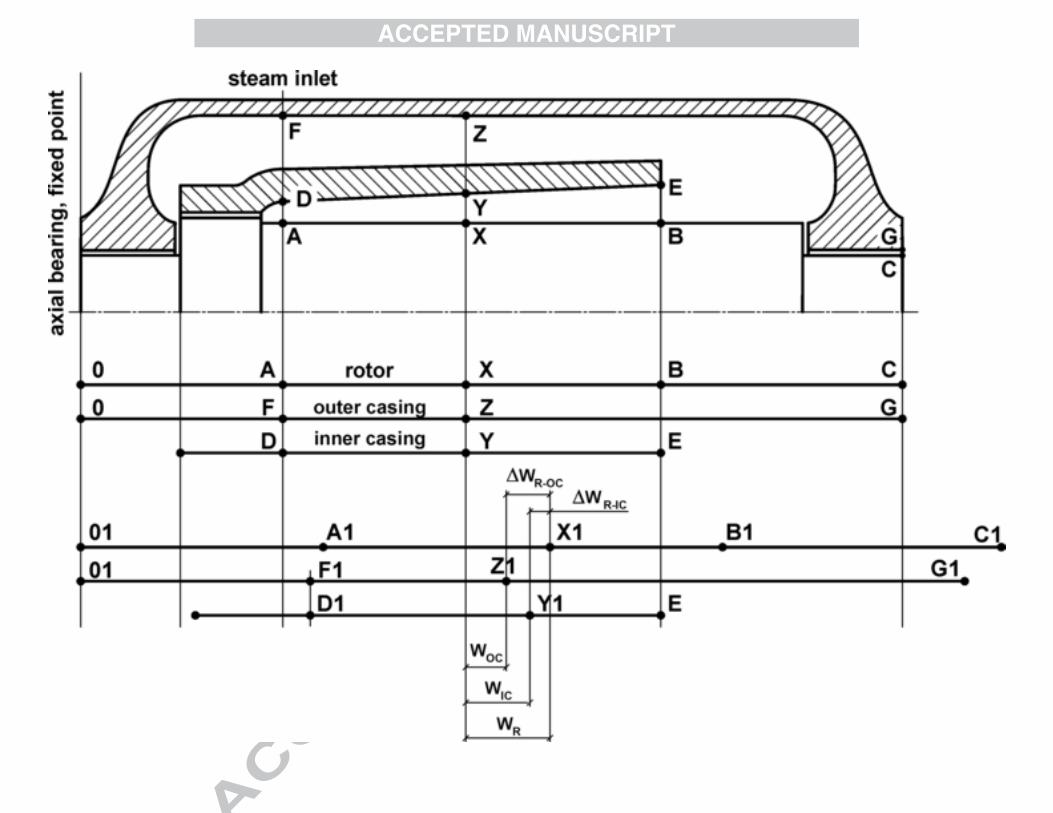
a). The analyzed object are the high pressure rotor (R), internal casing (IC) and external casing (OC) of a supercritical steam turbine. The fixed point of the rotor is located at the axial bearing. In Fig. 1 it is assumed to be at point 0. The fixed point of the internal casing assembly is located on the axis of the steam inlet (cross-section A-D-F in Fig. 1).
b). The distributions of temperature T and pressure p along the steam path are obtained from a detailed analysis of the expansion process in consecutive stages, i.e., from the first stage to the last (Fig. 2):
n2,...,4,3,2ip,T i,si,s (1)
where: n is the number of stages.The developed model involves the algorithms and numerical codes described in
[18], which calculate the steam parameters at the outlets in consecutive stages. The input data for the calculations consists of the steam flow, the pressure and the temperature (ms,0 ,Ts,0 , ps,0) at the turbine inlet.
c). The steam temperature distributions in the internal and external casings glands are determined by the well-known relationships that describe the steam flow through seals [19].
d).The heat transfer between the steam and the components of the turbine involves a convection process with a known convective heat-transfer coefficient. The substitute coefficients [20] are applied to the locations where the rotor or casings interact with other components. In this way the surface of the rotor is divided into the areas exposed to the steam and the areas that interact with a row of blades.
ACCEPTED MANUSCRIPT
In transient problems, it is assumed that the convective heat-transfer coefficients on the surfaces of the analyzed components change along the axis of the turbine - z -and are dependent also on time in - t - by:
m,...,,jt,zf jj 21 , (2)
where: m - the number of distinguished characteristic surfaces.During a start-up the heat transfer coefficients may be related to the steam flow
by [19]:
m,...,2,1jm,zf 0,sjj (3)
e). The rotor and casing model is assumed to be a structure of revolution under axisymmetrical load. The displacements of each point of the deformed component (rotor or casing), which are in a cylindrical coordinate system (r, z, ) and are related to the initial configuration (assembly, cold state) are described by the displacement vector, u, [18]:
t,z,ruu,uu zr , (4)
which is related to the strain tensor εij = εij (r, z, t), (i, j = r, z) through the geometrical relationship:
z,rj,ii
u
j
u jiij
2
1(5)
If it is assumed that the component is fixed in the cross-section 0-0 (Fig. 1), then the thermal elongations are equal to the axial component of the displacement vector:
t,z,rut,z,rw z , (6)
From the equations (5) and (6) the thermal elongation of a component at coordinate z is equal to:
z
0
z dt,,rt,z,rw (7)
f). Finite element method is applied to the temperature, strains and stresses calculations. The ANSYS package is used in the calculations.
2.2 Design forms of the analyzed rotors
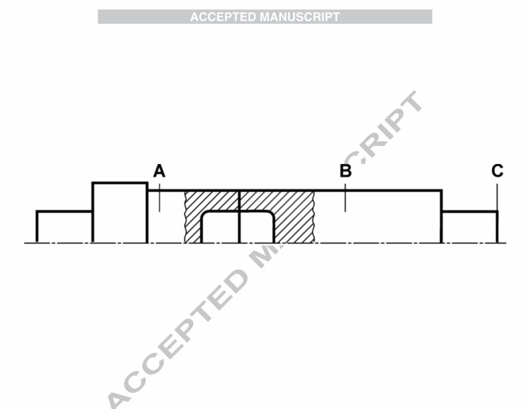
First, the numerical analysis involves welded rotor that is made of two discs (see Fig. 3). Three characteristic cross-sections are marked in figure 3: A is the steam inlet, B is the inner casing outlet, and C is the outer casing outlet. In these cross-sections the elongations time trends are analyzed.
ACCEPTED MANUSCRIPT
Three types of material are considered and applied to the rotors, casings and valves of the turbine. In later sections of this paper, the materials are referred to as: ferrite steel - symbol: F, martensitic steel - symbol: M, nickel alloys - symbol: Ni.
The discs of the welded rotors may be made of one of the above-mentioned materials. For the increased live steam parameters, the first disc (at the steam inlet area) may be made of nickel alloys, while the outlet section may be made of either martensitic or ferrite steel.
3. Thermal and strength properties of ferrite and martensitic steel and nickel alloys
The increased parameters of the live steam drive the application of the advanced materials. Thus, an examination was conducted of the available materials currentlyapplied in the area of power engineering that satisfy the requirements of supercritical steam turbines. In each of the groups F, M and Ni, a model steel was chosen.
According to Kosman and Roskosz [20], the new martensitic-ferrite steel with 9-12.5% chromium, is highly resistant to creep and may be applied up to a temperature of 620oC. According to [21] the martensitic steel VM12 may even be applied up to a temperature of 630oC.
The group of analyzed also includes ferrite steels, which may be applied up to a temperature of 540oC. However in the parametrical calculations it is assumed that the temperature of the live steam equals Tp,0 = 600oC. Thus, under such a condition, the results for the components made of ferrite steel may only be treated as a reference values for other materials.
The coefficient of thermal expansion, , is lower for the martensitic steels than for the ferrite steels and nickel alloys (Fig. 4), which affects the elongations of the components. The convective heat transfer coefficients are shown in Fig. 4. In this case, the thermal convection in the nickel alloys is definitely smaller, which affects the temperature differences at the components walls and the stresses within the material.
4. The influence of the type of material on the thermal elongations of the turbine components in the steady state
The components under analysis are the rotor and inner casing of the model turbine shown in Fig. 1. This figure presents the constraints and the fixed points of the casings and rotor. On this basis, thermal elongations may be tracked for each component.
The internal casing elongates from the fixed point “0” along the turbine axis. The absolute elongation of the casing in the X-Y-Z cross-section of the turbine equals wOC = Z - Z1. Similarly the absolute elongation of the rotor is defined as wR = X - X1. The elongations of both the external casing and the rotor increase along the axis to reach a maximum values at the outlet, while:
ACCEPTED MANUSCRIPT
1GGw max,OC and 1CCw max,R (8)
The fixed point of the internal casing is located in the cross-section A-D-F presented in Fig. 1. In the cross-section X-Y-Z of the turbine, the elongation of the internal casing is wIC = Y - Y1.
The selection process for axial clearances must determine the relative elongations: rotor to internal casing wR-IC and rotor to external casing wR-OC. The relative elongations of the rotor and the casing in the X-Y-Z cross-section equal respectively (Fig. 1)
1Z1Xw OCR and 1Y1Xw ICR (9)
Likewise, for an arbitrary cross-section that is located at the coordinate “z”
zwzww OCROCR and zwzww ICRICR (10)
Modeling of the temperature distribution in the rotor and the casing assumes that the outer surface of the rotor and the inner surface of the casing are exposed to the same steam flow, which changes temperature Ts,i along the turbine axis (see Fig. 2 and equation (1) ). The heat exchange rate differs for both components and is characterized by the convective heat coefficients R,j and IC,j. These coefficients vary along the turbine axis and depend on the live steam flow (3).
In the steady state, the temperature distributions in the rotor and the casing are first calculated, then the absolute elongations are calculated, followed by the relative elongations between the rotor and the inner casing.
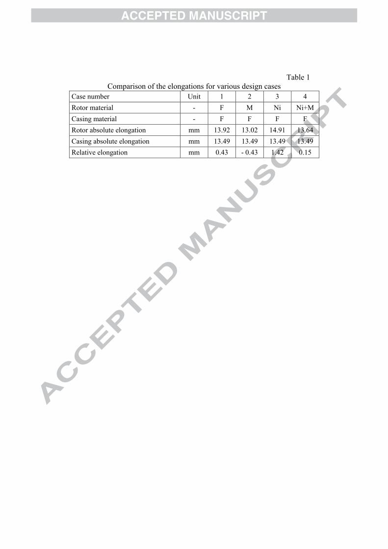
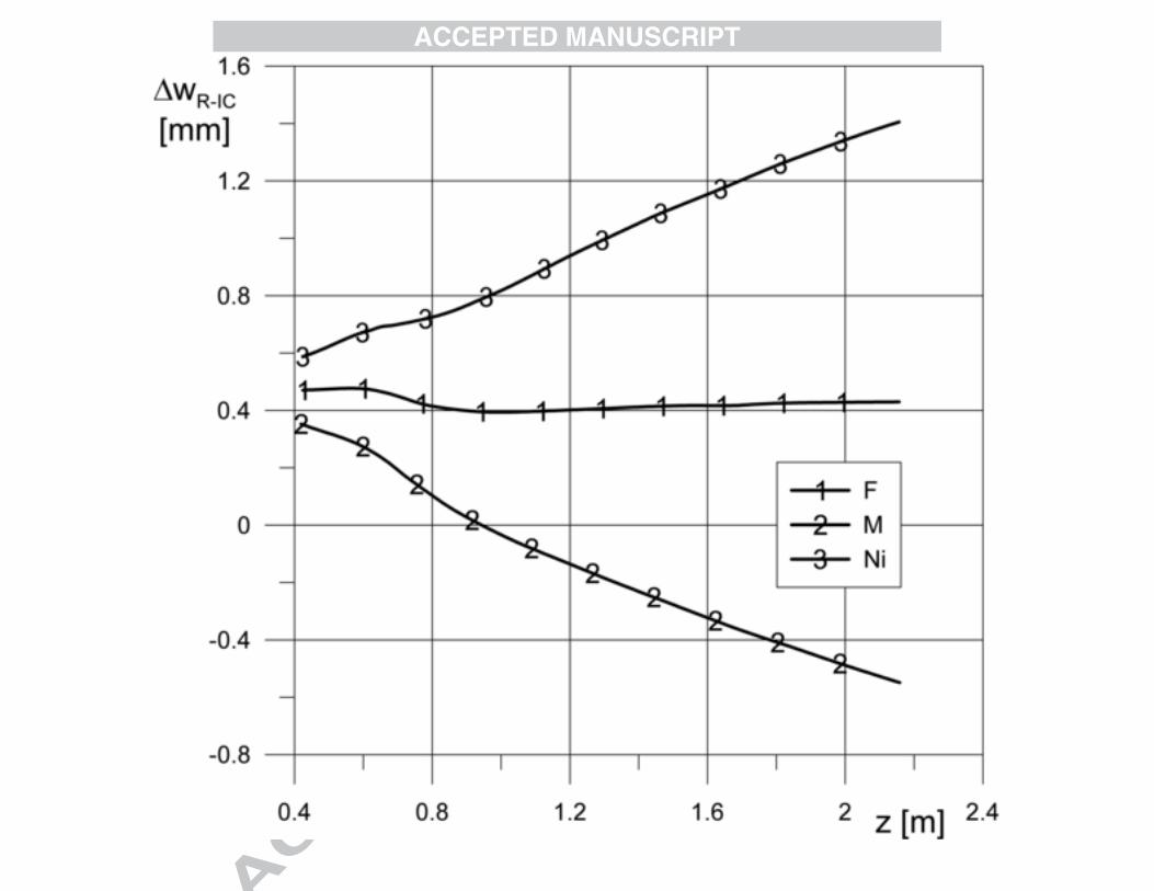
The results of the calculations are shown in figs. 5 and 6. The steam temperature at the turbine inlet (cross-section A in Fig. 5) equals 600 oC and decreases to 380 oC (cross-section B) along the steam path due to the expansion process. The maximal rotor temperature is just slightly lower than the maximal steam temperature and equals 595 oC. The absolute elongation of the rotor increases with the distance of the cross-section from the fixed point and reach the maximal value at the opposite end (Fig. 5). Similar calculations were conducted for the inner casing, which then allows the relative elongation from the rotor to the inner casing to be determined. The distribution of the relative elongations along the turbine axis is shown in Fig. 6. The graph compares the elongations calculated for cases in which the rotor is made of the F steel, M steel or the Ni alloys. In each case, the inner casing is made of the ferrite steel F. The values of the relative elongations in the outlet cross-section of the inner casing (cross-section B) for various materials are shown in Table 1.
Based on Fig. 6 and Table 1, it is possible to determine the influence of the type of material on thermal elongations. The M and Ni materials behave differently than the ferrite steel F. The relative elongations are negative for the rotor made of the martensitic steel, which means that the absolute elongation of the rotor is smaller than the casing elongation. For the two remaining materials the situation is quite the opposite. However, this does not cause any problems for the turbine as long as the elongations are taken into consideration at the design stage, when the axial clearances are chosen.
ACCEPTED MANUSCRIPT
5. Time trends of the thermal elongations during a start-up
The start-up process is conducted according to the start-up characteristic, which defines the changes in the live steam temperature, the flow rate and the rotational speed:
tfn,tfm,tfT 0,s0,s (13)
A start-up characteristic from a cold state is developed for the model turbine that has been analyzed (Fig. 7). The live steam flow change is described by the values related to the design flow rate - ms,0,nom - at full turbine load.
The characteristic serves as a base for modeling the expansion process in the steam path during the start-up. The calculations assumed a constant time step t.
For an arbitrary start-up time the live steam parameters (Ts,0 and ps,0 ) and the flow rate - ms,0 - are determined from Fig. 7. For these values, further calculations are conducted as described in the section 3.1.c. The results of the calculation provide the parameters of the steam at the outlets of the consecutive rows of blades for time steps tj
= j t.
jipj,i,sjiTj,i,s t,zfp,t,zfT (14)
where: n is the number of stages, k is the number of time steps, i = 2, 3, 4, ...., 2n and j = 1, 2, ..., k.
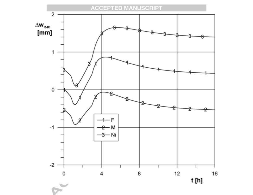
An example of the time trends for the relative elongation - ww-kw - from the rotor to the inner casing during a start-up is shown in figs. 8 and 9. During the first stage of the start-up the relative elongation quickly reaches a maximum value. Later on, as the temperature of turbine components increases, the relative elongations decrease. After a longer period of heating the thermal elongations become stable and reach steady state. Such a tendency occurs in each of the analyzed cross-section (Fig. 8 and 9).
The relative elongations clearly depend on the distance from the fixed point of the turbine (point 0 in Fig. 1). In the outlet cross-section of the inner casing (cross-section B in figs. 1 and 3) the elongations wR-IC are larger than in the cross-section A (compare trends shown in Fig. 8 and 9). Depending on the material type, the relative elongation of the cross-section B not only changes in value but also in sign.
The influence of the type of material on the thermal elongations is most visible the in the outlet cross-section of the inner casing (Fig. 9). The materials M and Ni behave differently when compared to the ferrite steel F. The smallest relative elongations occur in the rotor made of martensitic steel, while the largest occur in the rotor made of nickel alloys. The maximal difference between the elongations for rotor made of martensitic steel and nickel alloys reaches 2 mm. These conclusions should be taken into consideration when the axial clearances are set in the turbine.
As mentioned in section 3.2, the welded rotor may consist of two different materials that are chosen with respect to the temperature and the stress levels of the rotor. In the presented research it is assumed that the first disc (in the steam inlet area) is made of nickel alloys and that the outlet section is made of martensitic steel.
Figure 10 compares the time trends of the relative elongations for the two rotors. The first rotor is only made of nickel alloys (Ni), while the second one consists of nickel alloys and martensitic steel (Ni+M). The elongations time trends for the rotor made of
ACCEPTED MANUSCRIPT
nickel alloys are the same as in Fig. 8. A characteristic feature of the Ni+M rotor is that the relative elongations are close to zero in the steady state. The elongations values in the steady state are also given in the Table 1.
6. The relationship between the relative elongations and the heating process
The values of the relative elongations presented so far correspond to a start-up conducted according to the characteristics shown in Fig. 7. Different results are obtained for a shortened start-up, when the rates of change of the steam parameters and the flow are assumed to be twice as fast.
The results of the calculations are shown in Fig. 11. For such shortened start-up conditions the heating process is much more intensive, the temperature of the components increases faster and as a result the relative elongations are more dynamic.
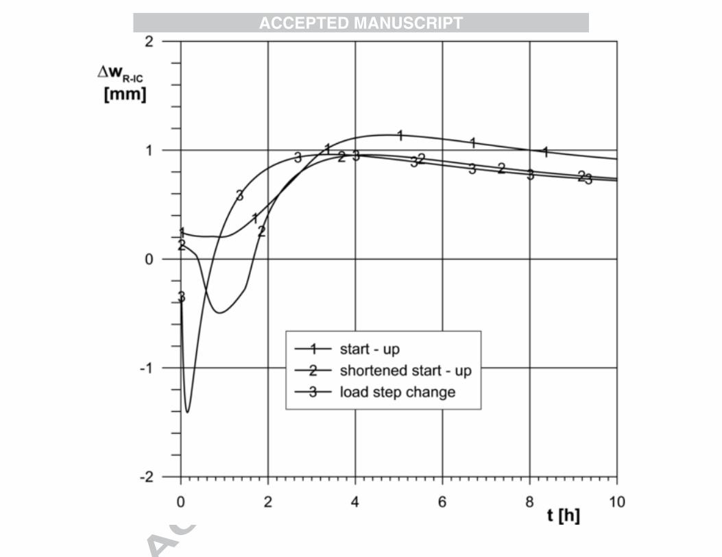
Additional analysis concerns the thermal elongations of the turbine components in the transient state of operation, i.e., when the load changes immediately from zero to its nominal level (a "step change"). The heating is the most intensive in this case and the relative elongations have the most dynamic time trends. The results obtained from this additional analysis describe the most inconvenient state of the elongations.
Figure 11 compares the time trends of the relative elongations at the outlet cross-section of the inner casing (cross-section B in Fig. 3) for various start-up cases. The rotor under investigation is welded. It is made of nickel alloys at the steam inlet area (the first disc in Fig. 3) and martensitic steel in the remaining sections (the second disc). For the start-up conducted according to the characteristic in Fig. 7 the relative elongations are only positive, which means that the absolute elongations of the rotor are always larger than the elongations of the casing. For the shortened start-up and for the load step change the relative elongations are negative during the first stage of the start-up.
The step change in the load causes a near step change in the casing elongations and an almost identical change in the relative elongations. The maximal absolute value of the negative elongations is higher than the positive values, which occur later during the start-up.
7. The influence of the rotor design form on the relative elongations
In order to assess the influence of the rotor design on the relative elongations it is relevant to repeat the calculations for the rotor forged as a single piece. These results may be compared to the previous ones that correspond to the welded rotor. It is assumed here that both rotors are made of the ferrite steel F (as is the casing). The analysis of the thermal elongations involves the start-up, which is conducted according to the characteristics shown in Fig. 7.
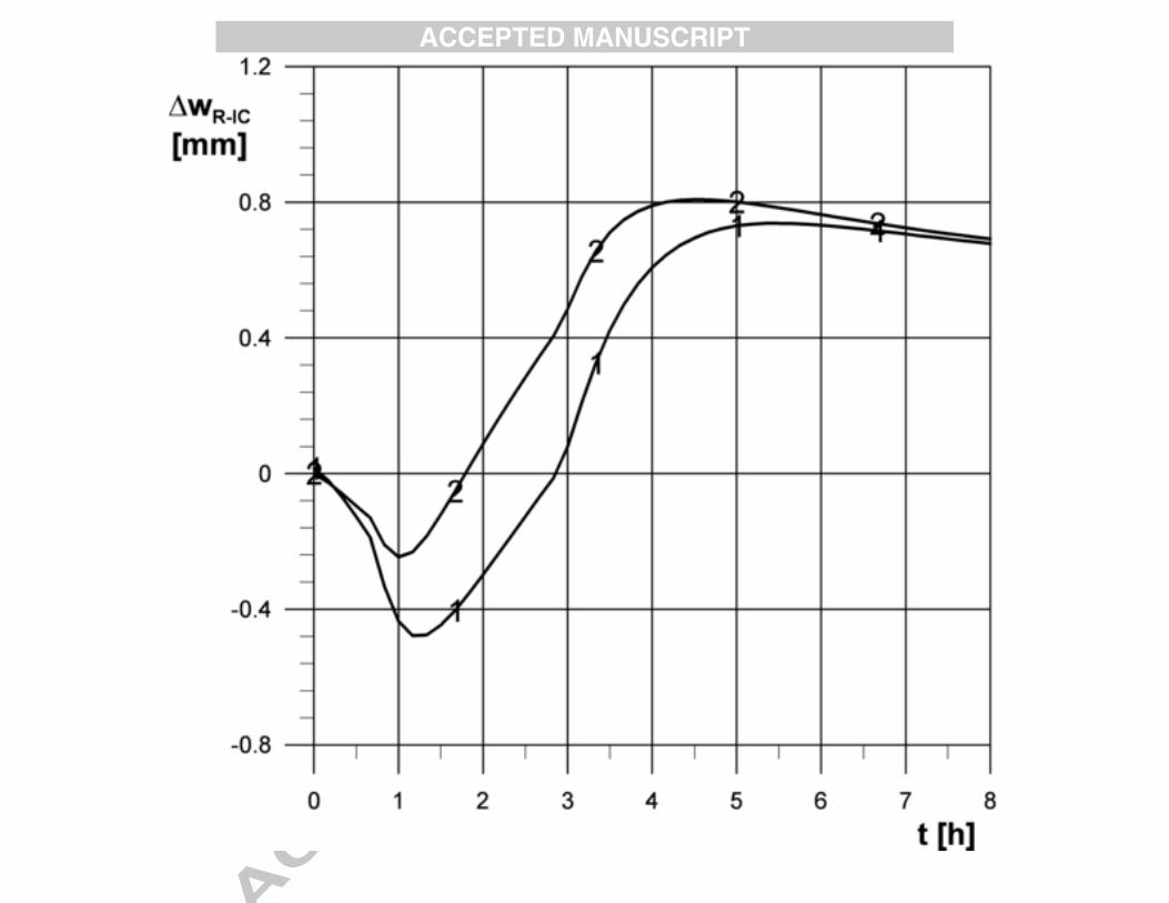
The results of the calculations are presented in Fig. 12. The results refer to the outlet cross-section of the inner casing because in this location the influence of the design form is the most evident. Generally it must be noted that this influence is significantly smaller in comparison to the influence of the type of the material, which was described earlier.
ACCEPTED MANUSCRIPT
Differences between the elongations in the rotors appear during the first stage of the turbine start-up. In later stages of the heating process the time trends tend towards the steady state, which is almost identical for both forms of the rotor.
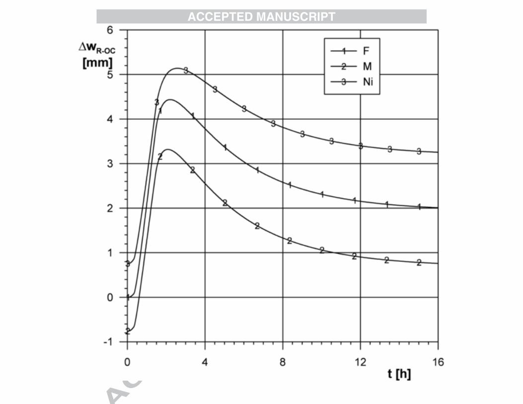
8. Relative elongation rotor - outer casing
The final stage of this research is related to the thermal elongations of the rotor and the outer casing. The analysis again concerns the heating process conditions described by the start-up characteristics in Fig. 7.
Figure 13 presents the relative elongations between the end of the outer casing on the steam outlet side (cross-section C in Fig. 1) and various models of the rotor. This figure corresponds to Fig. 9 for the inner casing. In this case the most intensive change in thermal elongations occurs during the first stage of the start-up. Materials M and Ni perform differently than the ferrite steel F. The smallest relative elongations occur in the rotor made of martensitic steel, while the biggest for nickel alloys. The relative elongations between the rotor and the outer casing (Fig. 13) are much larger than the elongations between the rotor and the inner casing (Fig. 9). This fact must be taken into consideration when the axial clearances are set for a turbine.
9. Comparison between the calculation results and measurement data
In order to verify the developed model a comparison is performed between the calculated and measured relative elongations of the rotor and the outer casing. The elongations is measured at the end of the casing on the steam outlet side. The analyzed machine is not a supercritical steam turbine but a conventional one, since this turbine is available for testing. The turbine type, however, has no effect on the verification of the model.
The modeling of the thermal elongations for the rotor and the casing is based on the measurements of the rotational speed (n), the live steam temperature (T), the pressure (p) and the flow (m). The measurement results gathered in Fig. 14 correspond to the start-up from a cold state.
The results of the calculations of relative elongations are shown in Fig. 15, where they are plotted against the measurement data. The comparison proves that the numerical simulation reflects the measured trend in a satisfactory manner. The maximal difference between the measured and calculated trend does not exceed two percent. Therefore the verification proves that the model developed for the calculations of the elongations is correct.
10. Conclusions
The axial elongations measurement is relatively easy in the outlet cross-section of the outer casing (cross-section C in Fig. 1). This represents the relative elongations between the outer casing and the rotor. During standard operation, the elongations are not supervised “inside the turbine” (neither in the steam path nor in the external glands), which is the reason why the research presented here primarily analyzed the relative
ACCEPTED MANUSCRIPT
elongations between the rotor and the inner casing. Since the experience gathered from the operation of supercritical steam turbines with components made of new materials is so far insufficient, numerical simulations may significantly complement the knowledge bases. This analysis focused on determining the effects of the material type, design form and start-up heating process on the thermal elongations of the turbine components.
The obtained results presented in this paper prove that the advanced materials and their range of applications significantly affect the values of the relative elongations between the rotor and the inner casing as well as the axial clearances set during the assembly process. It is shown here that the materials M and Ni perform much differently than the ferrite steel F. This difference is best represented for the steady state by the results shown in Fig. 6 and Table 1. Even larger differences occur for transient conditions (figs. 8 - 10). A very small relative elongations may be obtained for a welded rotor made of two different materials (nickel alloys and martensite steel), shown in Fig. 10. All of the presented results indicate that the advanced materials change the operational conditions of supercritical steam turbines when compared to traditional materials.
The influence of the rotor design form is small when compared to the influence of the material type.
This research proves that the immediate load change from zero to its nominal level (a "step change") results in the most intensive heating process in the turbine components. The time trends of the relative elongations are the most dynamic. The obtained results are relevant to the most inconvenient elongation state, which is important to consider when axial clearances are selected.
The conclusions in this paper provide essential information as well as procedures to support the assembly and operation control processes of the supercritical steam turbines.
AcknowledgementsThis research was financed by the Polish Ministry of Science and Higher
Education, grant No G 005/T02/2007 (PBZ-MEiN-4/2/2006), 2007-2010.
References
[1] A. Wichtmann, M. Deckers, W. Ulm, Ultra-supercritical Steam Turbine Turbosets Best Efficiency Solution for Conventional Steam Power Plants, VGB Power Tech 11/2005, pp. 44-49.
[2] N. Kolev, K. Schaberb, D. Kolev, A new type of a gas-steam turbine cycle with increased efficiency, Applied Thermal Engineering 21 (2001), pp. 391-405.
[3] S. Kjaer, F. Klauke, R. Vanstone, A. Zeijseink, G. Weissinger, P. Kristensen, J. Meier, R. Blum, K. Wieghardt, The Advanced Supercritical 700oC Pulverised Coal-Fired Power Plant, VGB PowerTech 7/2002, pp. 46-49.
ACCEPTED MANUSCRIPT
[4] W. Ulm, The situation in steam turbine construction and current development trends, Operation Maintenance and Materials Issues vol. 2, issue 3, 2003, paper number 77
[5] V. Prisyazhniuk, Alternative trends in development of thermal power plants, Applied Thermal Engineering 28 (2008), pp. 190-194.
[6] W. Engelke, J.C. Franc, R.B. Scarlin, L. Busse, Turbine designs with new steels for high steam parameters. II: manufacturer-specific design characteristics, VGB Kraftwerkstechnik 74 (1994), Heft 4, pp. 346-360.
[7] V. Jensen, Experience gained from commissioning a new 411 MW coal-fired plant with advanced steam data, VGB KraftwerksTechnik 5/2000, vol. 80, pp. 70-76.
[8] K.H. Mayer, W. Bendick, R.U. Husemann, T. Kern, R.B. Scarlin, New Materials for Fossil-Fired Thermal Power Stations, VGB PowerTech 1/98, pp. 22 - 27.
[9] S. Birks, Very heavy section 9Cr martensitic steel castings of USC applications: Developments for 700 C applications, Operation Maintenance and Materials Issues vol. 5, issue 3, 2008.
[10] R. Knoedler, S. Straub, B. Scarlin, KOMET 650 - Investigation of Materials for Use in Steam Turbines at Temperatures up to 650 oC, VGB PowerTech 3/2008, pp. 59 - 62.
[11] Tachibana-wan unit 2 takes a supercritical step forward for Japan, Modern Power Systems, 2001, Vol. 21, issue 11, pp. 41-44.
[12] K. M. Retzlaff and G. Schlottner, Steam Turbines for Ultrasupercritical Power Plants, POWER-GEN 1998 Europe, Milan.
[13] K. Wieghardt, Siemens Steam Turbine Design for AD700 Power Plants. AD700 Conference Milan 2005.
[14] H. Oeynhausen, A. Drosdziok, M. Deckers, Steam Turbines for the New Generation of Power Plants, VGB Kraftwerkstechnik 12/1996, vol. 76, pp. 974-979.
[15] Pirschter A., Alstom Steam Turbine Designs for AD700 Power Plant. AD700 Conference Milan 2005.
[16] Ch. Folke, H. Tschaffon, F. Bierewirtz, Von COMTES 700 zu 50plus -Entwicklungsschritte auf dem Weg zum Kohlekraftwerk mit 50% Wirkungsgrad, 39. Kraftwerkstechnisches Kolloquium 2007, pp. 94 - 107.
ACCEPTED MANUSCRIPT
[17] W. Kosman, Thermal analysis of cooled supercritical steam turbine components” 21st International Conference ECOS 2008, conference paper number: EGY-D-08-00371.
[18] T. Chmielniak, W. Kosman, Expansion Line Modeling and Strength Diagnostics of Internally Cooled Gas Turbine, ASME TURBO EXPO 2004, Vienna, Austria, conference paper number: GT2004-53550.
[19] T. Chmielniak, G. Kosman, Thermal Loads of Stream Turbines (in Polish), WNT Warsaw 1990.
[20] G. Kosman, M. Roskosz, Solution of inverse heat conduction problem for thermal stresses analysis in turbomachinery rotors, Congress of Thermal Stresses, Vienna, 2005.
[21] Cases of ASME Boiler and Pressure Vessel Code, Cases 2179, 2180, 2199.
[22] B. Hahn, W. Bendick, Stand der Werkstoffentwicklungen für neue Kraftwerke, VGB PowerTech 6/2006, vol. 86, pp. 45-55.
ACCEPTED MANUSCRIPT
Figure captions
Fig. 1. The model turbine
Fig. 2. Steam path in a turbine
Fig. 3. Welded rotor
Fig. 4. Coefficients of thermal expansion and convective heat transfer
Fig. 5 Distribution of the temperature and absolute elongations in the rotor for a steady state
Fig. 6 Distribution of the relative elongations for a steady state
Fig. 7 Start-up characteristic for the model turbine
Fig. 8 The relative elongations in cross-section A (Fig. 3) during a start-up
Fig. 9 The relative elongations in cross-section B during a start-up.
Fig. 10 Comparison of the relative elongations in cross-section B for the rotor made of one and two materials.
Fig. 11 The relative elongations in the cross-section B during a start-up for various start-up cases.
Fig. 12 The relative elongations in the cross-section B during a start-up for (1) a forged rotor and (2) a welded rotor
Fig. 13 Time trends of the relative elongations at the outlet cross-section of the outer casing for various design cases of the rotor
Fig. 14 Time trends of the parameters in the chosen locations of the turbine during a start-up
Fig. 15 Comparison between calculated and measured relative elongations
ACCEPTED MANUSCRIPT
Table 1Comparison of the elongations for various design cases
Case number Unit 1 2 3 4
Rotor material - F M Ni Ni+M
Casing material - F F F F
Rotor absolute elongation mm 13.92 13.02 14.91 13.64
Casing absolute elongation mm 13.49 13.49 13.49 13.49