Thermal expansion analysis of and experiment on a high speed vertical motion ball-screw
C.-C. Wei, J.-H. Horng, L.-C. Hsieh, X.-H. Hsu & C.-Y. Lin Department of Power Mechanical Engineering, National Formosa University, Taiwan, ROC
Abstract
A high-speed transmission table is widely used in industry with an increased demand. The preloaded ball-screw device is a major component in a transmission system. To bear the applied load, the preload and inertial forces, a four-cycle ball-screw is necessary. The kinematic behaviour and friction of the ball and raceway are more complex than the double-cycle ball-screw. A new calculation concept is used to simplify the complex calculation. Contact and friction were found at each cycle, and they varied with operating conditions such as the applied axial load and the rotational speed. The study is helpful in realizing the contact and friction behaviour in a preloaded, four-cycle ball-screw. The calculated results are well confirmed with the surface strain, and the temperature of the experiments was obtained from the vertical motion of a high-speed ball-screw system. The thermal expansion behaviour of a nut is found to be similar to its linear thermal expansion function. Keywords: ball screw, high speed, thermal expansion, four cycles.
1 Introduction
Due to the need for precision technology, tool machine and precision machine centres are required for high speed, high accuracy, long life and automation. High-speed ball-screws are a key transmission component in a fast fabrication instrument. A high speed ball-screw is defined with linear speed over 90 m/min, acceleration at 9.8 m/s2, and high positioning accuracy, high stiffness, and low transmission vibration. High speed transmissions bring high friction heat that occurs at the contact area of the ball and the raceway; the friction leads to thermal expansion [1]. Variation of the contact geometry of the ball, screw and
Surface and Contact Mechanics including Tribology XII 233
nut will affect positioning accuracy. However, the variation of the contact geometry of each component in a ball-screw cannot be discovered by experiment. Positioning error of a high-speed ball-screw can be observed by the optical ruler and is related to the thermal expansion coming from the nut and screw. Skidding, which occurred at the contact areas of the ball-screw and the ball-nut, is the main cause of positioning errors [2]. Skidding is generated from the effects of friction and the elastic deformation formed by the sliding and contact forces, respectively. The ball-screw mechanism is a closed system. It is difficult to directly investigate what occurs on the inside of a ball screw when it is moving. It is feasible to use numerical analysis to solve several kinetic parameters in terms of the kinematics and dynamics of this system. Then, expressions are built for such performance parameters as the friction coefficient, the slide–roll ratio and the mechanical efficiency. The kinematic behaviour of the ball screw is similar to that of a ball bearing; the analytical method applied in the analysis of a ball bearing can thus be exploited to modify the ball-screw motion. Harris [3, 4] analysed how the skidding behaviour arising between the balls and the inner raceway, where rolling surface distress is induced, can eventually lead to bearing destruction. The model developed in Harris’s study is cited in the present study to find the contact angles of the ball screws, as well as several angular velocities through geometric transformation. Contact geometry and friction of the contact areas varied greatly when the screw rotation is operating at low and high speeds. These two speed sub regions are usually bordered at 1000 rpm. The distinctions due to the high rotational speeds are caused by a significant increase in the centrifugal force of the balls [5] and the slip motion formed at the ball and the raceway. The centrifugal force of a ball operating at a high rotational screw speed was presented as a function of the screw rotational speed and the axial load applied in the nut [5]. The increase in the centrifugal force of a ball leads to an increase in the frictional force and thermal heat, which causes thermal expansion and greater positioning error. In the present study, a vertical motion ball-screw testing instrument was used to investigate the relationship between the theoretical analysis and the experimental measurements of the thermal expansion of the nut when the ball-screw is driven at high speed with an axial load. A four-cycle offset preloaded type ball-screw model is presented.
2 Analysis method
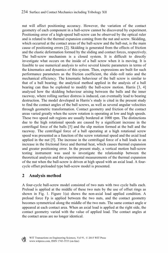
A four-cycle ball-screw model consisted of two nuts with two cycle balls each. Preload is applied at the middle of these two nuts by the use of offset rings as shown in Fig. 1. Figure 1(a) shows the non-axial load applied condition. A preload force Fp is applied between the two nuts, and the contact geometry becomes symmetrical along the middle of the two nuts. The same contact angle α。 appeared at each contact area. When an axial load is applied at the right side, the contact geometry varied with the value of applied load. The contact angles at the contact areas are no longer identical.
234 Surface and Contact Mechanics including Tribology XII
(a)
(b)
Figure 1: Contact geometry of the four cycle, double nut ball-screw, (a) non-axial load, (b) with axial load.
A kinematic analysis method is established for calculating the contact forces, the oil film thickness and the frictional forces to obtain the heat flux value, as shown in Fig. 2. The contact pair is defined as the left and right contact side. For the first step, the two recycling loops of each nut are assumed to have axial symmetry and bear the same load. The two-cycle ball-screw calculating method is thus used to obtain the applied load at each nut. The calculating method can be followed with a study from 2009 [6]. Then, the load at each of the two nuts can be calculated by non-preload conditions and converged by the force equilibrium of each nut. In the calculating flow chart, the right contact side is calculated first until the axial load applied at nut is in equilibrium with the contact, friction and centrifugal forces. The left contact side load is then calculated by the same method. The kinematic simulation is thus calculated by these two ball cycles and then converged by the force equivalent equation on the nut side. The lubrication calculation uses the EHL theory, and the different temperature and shear rates help to experimentally measure the viscosity of the grease, as shown in Fig. 4. The sliding speed Vs, the friction f and the contact area AH of the contact region between the ball and the raceway are obtained by calculating the heat flux q, as shown in Eq. (1).
Surface and Contact Mechanics including Tribology XII 235
Figure 2: Calculation flow chart.
The heat partition ratio between the ball and nut is shown in Eq. 3[7], which is established in a ball on plate model.
npiseb
npisein
ckvrk
ckvrR
)()(807.0
)()(807.0
,
,,
(2)
where, w
ck )( and nck )( are the heat conductivity coefficient of the
raceway of the ball and nut, respectively. Considering the acceleration to be steady and deceleration to be in stages, the rotational speeds are varied from 0 rpm to 3000 rpm. Heat flux is generated by different rotational speeds, and they are averaged by their processing time and summarized in one stroke.
236 Surface and Contact Mechanics including Tribology XII
3000
100,
,,, )()()(64
1
iinRi
cR
isRiRioRpR Rt
A
VQ
Sq
(3b)
The heat flux of the contact area is a boundary condition of the finite element model. The model is solved by Ansys software (Ansys Inc., USA); the calculating coefficients are shown in Table 1. On the flange of the nut, the impinging flow boundary was given as shown in Fig. 3; around the body of the nut is a heat conduction condition. From the study of Kobus and Shumway (see
[4]), the average heat convection factor h is obtained by the Nusselt number and the conductive factor of air at ambient temperature ( -31026.3 W/m k)
D
966.0 3146.0
1 airreairu kPR
D
kNh D
(4)
where, the Reynolds Number /eR VD , D is diameter of the flange of the nut
( 31095 m), is the viscosity of the ambient air ( 61089.15 m2/s), V is the flow speed of the air, which is dependent on the rotational speed of the air, and Pr is the Prandtl Number, 0.707.
Table 1: Ansys workbench coefficients.
Figure 3: Impinging flow boundary given at the edge of the nut flange.
Ansys workbench coefficients Analysing type Steady heat
Steady structure Grid Type Four face body
Nude number 120605 Element number 75616
Material parameters Type Bearing steel SUJ2 Young’s modulus 21011 GPa Poisson ratio 0.3 Tensile strength 2.5108 GPa
Surface and Contact Mechanics including Tribology XII 237
3 Experiment
Tests to determine the thermal expansion were conducted on a vertical motion ball-screw test machine, as shown in Fig. 4(a). The test machine consisted of several components: a servo-motor, a torque meter, a ball-screw, a load cell and a holder fixed on the housing of a nut. The servo-motor was the primary power supply source. The maximum torque supplied was 15.8 Nm, the acceleration was 9.8 m/s2, and the maximum rotational speed was 3000 rpm. An axial load of 200 kgf was applied on the holder, which was connected with the nut of the testing ball-screw. The stroke was 410 mm and lubricant used was grease with a base oil viscosity of 40 cst at 40ºC. Detail parameters of the testing ball-screw are shown in Table 2. The temperature of the screw was obtained by a thermal imaging device located behind the machine frame; the device captured the screw surface temperature every minute. The temperature of the nut was obtained by four T-type thermocouples that were buried in holes nearby the raceways, as shown in Fig. 4(b). Thermal elongations were calculated by the linear expansion equation
nLTL 6106.11 (5)
where L is the thermal elongation length, ΔT is the thermal rising of nut, and Ln is the total length of nut. One dozen strain gages were also installed on the side of the raceway on the surface of the nuts, as shown in Fig. 4(b). The surface strain of the nut is useful in determining the variance of the contact deformation with an applied load and can be used in confirming the results with the theoretical analyses.
Figure 4: (a) Experimental instrument; (b) temperature rising measurement.
238 Surface and Contact Mechanics including Tribology XII
Table 2: Parameters of the testing ball-screw (from the catalogue of Hiwin Corp.).
Type R32-16k2-FDC-598-776-0.018
Parameter Value Unit Helix angle 8.67 Degree
Cycles of each nut 2 Lead 16 mm
Curvature of raceway 3.429 mm Ball diameter 6.35 mm
Effect ball number 66 Preload 120 kgf
4 Results and discussion
The calculated results of the four cycle double nut ball-screw contact and the dynamic analyses are the boundary conditions for the Ansys simulation. The contact forces and the frictional forces occurred at the contact areas between the ball and the raceways; these forces are used in calculating the heat flux, as shown in Fig. 5. The contact forces are increased only with an applied axial load. An increase in the screw rotational speed increases the frictional forces. The contact and frictional forces affect heat flux by the use of Eq. (1), and they increase with the increase of the rotational speeds and axial loads.
0
2
4
6
8
10
16000
18000
20000
22000
24000
26000
28000
30000
0
5
10
15
20
25
30
35
40
Contact Force
Hea
t F
lux(
w/m
2 )
Fri
ctio
n F
orc
e(N
)
3000rpm200kgf3000rpm40kgf750rpm200kgf
Co
nta
ct
Fo
rce(
N)
750rpm40kgf
Friction Force Heat Flux
Figure 5: Contact, frictional forces and heat flux varying with operating conditions.
Surface and Contact Mechanics including Tribology XII 239
The deformation of the nut is originates from two sources: one source is the contact force in contact area and the other source is the thermal expansion produced by the frictional forces. Deformation of the nut is shown in Fig. 6(a). Because the flange of nut is fixed with the holder, the flange deformation is smaller than the other side. Thermal expansion is thus extended through the length of nut to the opposite, unfixed side. The contact forces of the right contact side are also much higher than on the left side, as shown in Fig. 6(b). Therefore, the deformation of the right side nut is also higher than the left side, owing to the effect of the higher contact forces.
(a)
0 120 240 360 4800
20
40
60
80
100
Rotational Speed 3000 rpmPreload 120 kgf
L1 L2 R1 R2
Co
nta
ct F
orc
e (N
)
Axial Load (kgf)
L1
L2
R2
R1
(b)
Figure 6: (a) Deformation of the nut; (b) contact forces vs. axial load.
The temperature distribution of the nut also shows the same trend as the deformation (as shown in Fig. 7). At the flange side, the temperature is lower than at the other position. Because the flange is fixed with the holder, the heat
240 Surface and Contact Mechanics including Tribology XII
conduction rate is higher than in the other area. The figure is also indicated that high rotational speeds bring higher frictional heat and cause higher temperature rises on the nut.
(a)
(b)
Figure 7: Temperature distributions on the nut surface with an applied axial load of 40 kgf and rotational speed of screw as (a) 750 rpm and (b) 3000 rpm.
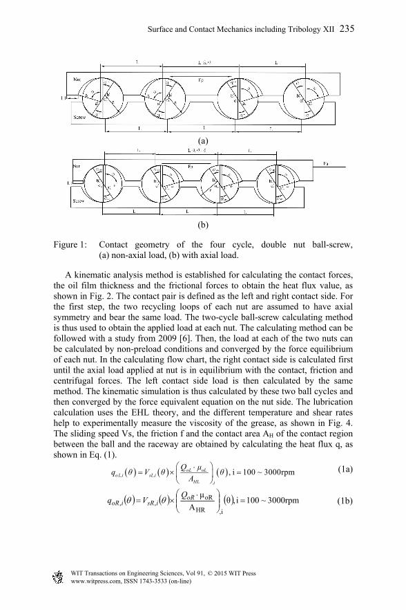
Confirmation is very important for the application of an analytical model. The surface strain of the nut is shown in Fig. 8. Experimental results and analytical data are well confirmed and the calculation error is less than 10%. The great data spread, marked with Fp, is the position of the offset ring between the two nuts. The surface strain of the left nut is lower than the right one due to low contact forces and thermal expansion. The strain is also increased with the increase of the axial load, owing to the rise in the contact forces (as shown in Fig. 6(b)). The surface temperature of the nut also appears with the same trend of surface strain (as shown in Fig. 9). A fine calculating error and tendency are revealed.
242 Surface and Contact Mechanics including Tribology XII
(a)
(b)
Figure 9: Surface temperature of the nut with different axial loads (a) 40 kgf and (b) 200 kgf.
After complex calculation and experimental processes, the question remains regarding other simple ways to achieve nut deformation. Eq. (5) is used to calculate the temperature and thermal expansion of the nut, which is the linear expansion function. The Ansys model also provided simulation results of the nut
32
33
34
35
36
37
Experiment Simulation
0.73% 1.25%1.11%0.56%1.54% 1.04%
Fp
Tem
per
atu
re(o C
)
Err
or(%
)
The Distance between Thermocouple and Flange End Face (mm)25.62 38.33 41.62 90.12 102.73 106.02
Specification:R32-16k2-FDC-598-776-0.018m
Acceleration:9.8 m/s2
Experimental Condition:3000 rpm 40 kgf
Ambient temperature:25.05 oC
35
36
37
38
39
40 Specification:R32-16k2-FDC-598-776-0.018m
Acceleration:9.8 m/s2
Experimental Condition:3000 rpm 200 kgf
Ambient temperature:26.05 oC
Experiment Simulation
0.85% 0.46%0.10%0.18% 0.43% 0.66%
Fp
Tem
per
atu
re(o C
)
Err
or(%
)
The Distance between Thermocouple and Flange End Face (mm)25.62 38.33 41.62 90.12 102.73 106.02
Surface and Contact Mechanics including Tribology XII 243
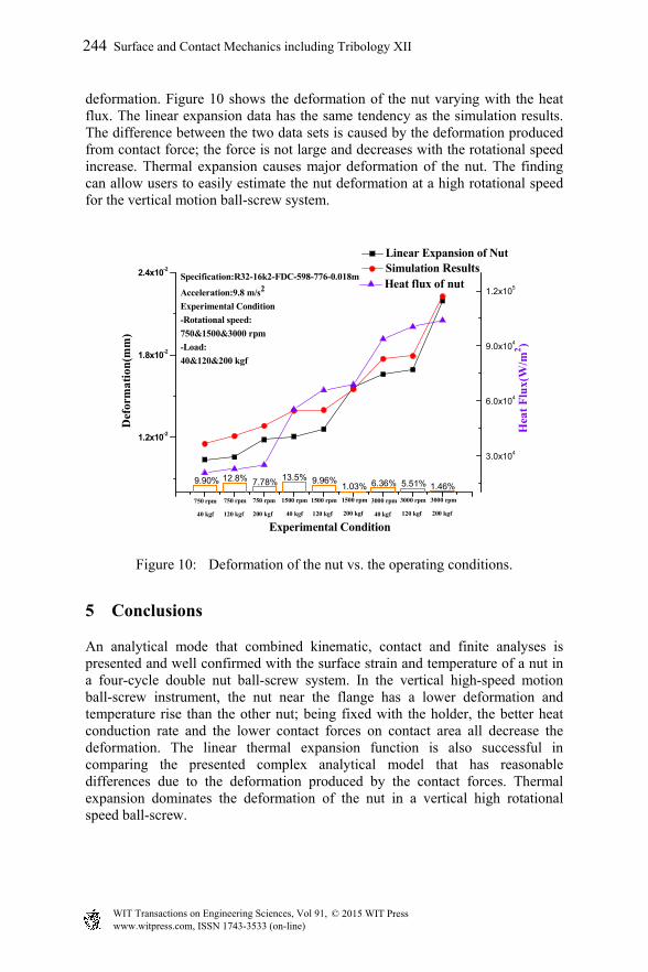
deformation. Figure 10 shows the deformation of the nut varying with the heat flux. The linear expansion data has the same tendency as the simulation results. The difference between the two data sets is caused by the deformation produced from contact force; the force is not large and decreases with the rotational speed increase. Thermal expansion causes major deformation of the nut. The finding can allow users to easily estimate the nut deformation at a high rotational speed for the vertical motion ball-screw system.
1.2x10⁻²
1.8x10⁻²
2.4x10⁻²
Hea
t F
lux(
W/m
2 )
Specification:R32-16k2-FDC-598-776-0.018m
Acceleration:9.8 m/s2
Experimental Condition
-Rotational speed:
750&1500&3000 rpm
-Load:
40&120&200 kgf
Linear Expansion of Nut Simulation Results
Def
orm
atio
n(m
m)
Experimental Condition
3000 rpm
200 kgf
3000 rpm
120 kgf
3000 rpm
40 kgf
1500 rpm
200 kgf
1500 rpm
120 kgf
1500 rpm
40 kgf
750 rpm
200 kgf
750 rpm
120 kgf
7.78%9.90%
750 rpm
40 kgf
1.46%5.51%6.36%1.03%9.96%13.5%12.8%
3.0x10⁴
6.0x10⁴
9.0x10⁴
1.2x10⁵ Heat flux of nut
Figure 10: Deformation of the nut vs. the operating conditions.
5 Conclusions
An analytical mode that combined kinematic, contact and finite analyses is presented and well confirmed with the surface strain and temperature of a nut in a four-cycle double nut ball-screw system. In the vertical high-speed motion ball-screw instrument, the nut near the flange has a lower deformation and temperature rise than the other nut; being fixed with the holder, the better heat conduction rate and the lower contact forces on contact area all decrease the deformation. The linear thermal expansion function is also successful in comparing the presented complex analytical model that has reasonable differences due to the deformation produced by the contact forces. Thermal expansion dominates the deformation of the nut in a vertical high rotational speed ball-screw.
244 Surface and Contact Mechanics including Tribology XII
Acknowledgements
The authors greatly thank the Hiwin Technology Company and the Ministry of Science and Technology of Taiwan for providing funds and for allowing us to finish this study. The project number is NSC-102-2622-E-150-002-CC2 and MOST-103-2221-E-150-013.
References
[1] Yun, W. S., Kim, S. K., and Cho, D. W., 1999, “Thermal Error Analysis for a CNC Lathe Feed Drive System”, International Journal of Machine Tools and Manufacture, 1999, 39: 1087-1101.
[2] Ro, P. I. and Hubbel, P. I. Model Reference Adaptive Control of Dual-mode Micro/macro Dynamics of Ball Screws for Nano-meter Motion, ASME Journal of Dynamic Systems, Measurement and Control, 1993, 115: 103-108.
[3] Harris, T. A., 1971, “An Analytical Method to Predict Skidding in Thrust-Loaded, Angular-Contact Ball Bearings,” ASME Journal of Lubrication Technology, Vol. 93, 17-24.
[4] Harris T. A., 1984, Rolling Bearing Analysis, John Wiley & Sons, New York.
[5] Wei, C.C., and Lin, J.F., 2003, “Kinematic Analysis of the Ball Screw Mechanism Considering Variable Contact Angles and Elastic Deformations”, ASME, J. Mech. Design, 125, 717-733.
[6] Wei, C.C., Lin J.F., and Horng, J.H., 2009, “Analysis of a Ball Screw with a Preload and Lubrication”, Tribology International, Vol. 42, 1816-1831.
[7] Kuo W.L., and Lin J.F., 2006, “General Temperature Rise Solution for a Moving Plane Heat Source Problem in Surface Grinding”, The International Journal of Advanced Manufacturing Technology, Vol. 31, No. 3-4, 268-277.