16
Thermal Fluid Heaters Vertical, Horizontal and Electric 75,000 - 14,000,000 BTU/HR

Thermal Fluid Heaters
Vertical, Horizontal and Electric
75,000 - 14,000,000 BTU/HR
Thermal-bro-053107:Layout 1 6/1/2007 2:54 PM Page 2

Thermal Fluid vs. Steam
A thermal fluid (hot oil) system operates in aclosed loop circulation system with minimalpressure. Fulton thermal fluid systems can reach750°F (345°C) making them an ideal choice formany process heat applications.
The choice between a steam system or a thermalfluid system is governed by the processrequirements. The range or process temperature isa deciding factor. If the system’s requiredtemperature is above the freezing point of water(32°F) and below approximately 350°F, the choiceis usually steam. However, if the requiredtemperature is below 32°F or above 350°F, thermalfluid may be a better solution.
Features
a few of the
• No corrosion or freezing
• High operating temperatures (up to 750°F) withlow system pressure
• Minimum maintenance – burner, pump andcontrols
• Simple circuit, no blow-downs, steam traps orcondensate return systems
• Fulton’s combination expansion/deaerator/thermal buffer tank provides pipeworksimplification, protection of thermal fluid fromoxidation and continuous deaeration of fluidavoiding pump cavitation
• Heaters are built and tested to ASME CodeSection I or ASME Code Section VIII Div. I
• Fulton heaters are manufactured individually formaximum flexibility and to customer specifications
• Fulton heaters and accessory components (pumps,expansion tanks, control valves, etc.) can be skidmounted to save time and on site fabrication
*Saturated steam or pressurized water
0°C 50°C 100°C 150°C 200°C 250°C 300°C 343°C32°F 122°F 212°F 302°F 392°F 482°F 572°F 650°F
0100200300400500
1000
1500
SYST
EM
PR
ESS
UR
E P
.S.I
.G.
SATURATED STEAM/WATERTHERMAL FLUID
SYSTEM FLUID TEMERATURE
• Fulton SteamPac• Fulton WaterPac
StorageTank
Fulton Deaeratoror Expansion Tank
Fulton ThermalFluid Heater
Press, Mold, orPlatten
Thermal-bro-053107:Layout 1 6/1/2007 2:54 PM Page 3

Applications
a wide range of
Bath orKettle
Fryer Reactor OvenRolls
Fulton heaters are used in a variety ofapplications throughout many industries.Food, plastic and chemical processingas well as pharmaceutical and bio-fuelproduction are only a few of the manyexisting applications using Fulton.
• Adhesives• Asphalt• Autoclaves• Bio-fuel• Chemical reactors• Deoderization• Distillation• Food processing (frying, baking, etc.)• Inks & Dyes• Laminating• Laundry• Marine heating and shipboard services• Metal finishing• Mining• Ovens• Paint and varnish manufacture• Paper converting machinery• Plastics• Printing and packaging machinery• Surface pretreatment and finishing• Tank farms/pipe and pump tracing• Textile machinery• Unfired steam or hot water generation• Uranium processing• Waste treatment/dryers
Thermal-bro-053107:Layout 1 6/1/2007 2:54 PM Page 4

The FT-0600-C shown below supplies 600°F thermalfluid for a food processing application. The skidincludes modulating valves to control fluid flow anda bypass valve to maintain flow throughout theheater at all times.
• Vertical 4-pass design
• Preheated combustion air is an integral part ofthe design
• Built and tested in accordance with ASME CodeSection I or ASME Code Section VIII Div. I
• 800,000 BTU/hr to 14,000,000 BTU/hr output
• Operating temperatures to 750°F
• Gas, oil or dual fuel burners; on/off ormodulating
• Low emissions natural gas burners are available
• Minimal refractory results in low thermal inertiaand prevents overheating of the fluid in theevent of a pump or power failure
• High efficiencies
• Even heating
• Customized controls available
Vertical Coil Design
features of the C-Model
Thermal-bro-053107:Layout 1 6/1/2007 2:54 PM Page 5
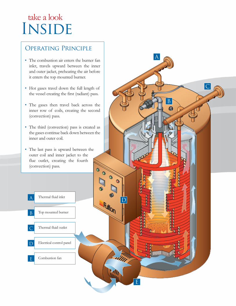
Thermal fluid inletA
Top mounted burnerB
Thermal fluid outletC
Electrical control panelD
Combustion fanE
Inside
take a look
Operating Principle
• The combustion air enters the burner faninlet, travels upward between the innerand outer jacket, preheating the air beforeit enters the top mounted burner.
• Hot gases travel down the full length ofthe vessel creating the first (radiant) pass.
• The gases then travel back across theinner row of coils, creating the second(convection) pass.
• The third (convection) pass is created asthe gases continue back down between theinner and outer coil.
• The last pass is upward between theouter coil and inner jacket to theflue outlet, creating the fourth(convection) pass.
B
A
C
D
E
Thermal-bro-053107:Layout 1 6/1/2007 2:54 PM Page 6

Specifications
Models FT-C 0080 0120 0160 0240 0320 0400 0600 0800 1000 1200 1400
Heat Output 1000 BTU/HR 800 1,200 1,600 2,400 3,200 4,000 6,000 8,000 10,000 12,000 14,0001000 KCAL/HR 200 300 400 600 800 1000 1500 2000 2500 3000 3500
Thermal Fluid Content GAL 10 21 19 31 68 76 132 171 290 383 460LITERS 38 80 72 116 258 288 500 648 1097 1450 1741
Recommended Flow Rate GPM 50 75 100 150 250 250 375 500 615 730 800M3/HR 11.4 17 22.7 34 56.8 56.8 85.2 113 139 167 182
Approximate Fuel Usage
Light Oil * GPH 7.1 10.7 14.3 21.4 28 35.3 53 69.7 87.1 104.5 122LPH 27 40.6 54.1 81 108.8 136 201 263.7 329.6 395.5 461.5
Natural Gas * FT3/HR 998 1,498 1,998 2,999 4,000 4,997 7,498 9,997 12,496 14,998 17,500M3/HR 28.3 42.4 56.5 84.9 113.2 141.5 212.3 283 353.8 424.6 495.5
Power
Typical Circulating HP 7.5 10 10 15 20 20 30 40 50 50 60Pump Motor KW 5.6 7.5 7.5 11.2 14.9 14.9 22.4 29.8 37.3 37.3 45Typical Burner Motor HP 1.5 3 3 3 7.5 7.5 7.5 15 20 20 25
KW 1.1 2.2 2.2 2.2 5.6 5.6 5.6 11.2 14.9 14.9 33.3
Voltage 3 Phase for Burner and Pump - Each unit has an incorporated stepdown transformer. Fuel up to No. 6 Oil Available for Large Units. (FT-0600-C and larger)Efficiency up to 80% Minimum Based on High Heating Value of the Fuel (No. 2 Oil @ 140,000 BTU/GHHV; Natural Gas @ 1000 BTU/ft3HHV.Modulation 3 to 1 Turn Down Ratio. Optional on FT-0080, 0120, and 0160 - Standard on all others.Circulating pump motor sizes based on standard pressure (55 PSIG) and viscosity 1 cs, specific gravity 0.7, with 25-37 PSID available head for installation.
Dimensions
Models FT-C 0080 0120 0160 0240 0320 0400 0600 0800 1000 1200 1400
Heater Inlet/Outlet Connections IN 1.25 1.25 2 2.5 3 3 4 4 6 6 6MM 32 32 50 65 80 80 100 100 150 150 150
(A) Overall Height IN 60 76 76 86 101 108 139 139 143.5 144 163MM 1,524 1,930 1,930 2,184 2,559 2,793 3,531 3,531 3,645 3,658 4,144
(B) Heater Diameter IN 25 34 34 40 49 49 57 71 90 108 108MM 6,35 8,65 8,65 1,015 1,252 1,245 1,450 1,805 2,285 2,745 2,746
(C) Overall Depth IN 41 56 56 62 80 70 79 103 130 148.5 153MM 965 1,422 1,422 1,525 2,030 1,780 2,007 2,615 3,302 3,772 3,894
(D) Flue Outlet Diameter IN 10 10 10 12 14 14 18 20 20 22 22MM 254 254 254 304 356 356 457 508 508 558 558
Recommended Vertical IN 10 12 12 14 18 18 22 24 24 26 26Stack Diameter MM 254 304 304 356 457 457 558 609 609 661 661Approx. Dry Weight LB 1,500 2,100 2,550 3,400 5,300 5,300 8,250 11,450 19,250 21,700 23,000
KG 680 953 1,150 1,550 2,400 2,400 3,750 5,200 8,750 9,850 10,455* Please consult factory for additional fuel options.Specifications and Dimensions are approximate. Consult factory for model specific electrical requirements.We reserve the right to change specifications and/or dimensions without notice.Operating specifications may change based on field conditions.
D
A
C
B
Diagram for guidance purposes only. Comprehensive details of dimensions, connections, etc. for each model are given on product dimension data sheets available from Fulton.
Top View Models FT-0080-Cthrough FT-0400-C
Top View ModelsFT-0600-C through FT-1400-CFront & Side Views Not Shown
Details (C-Model)
technical
Thermal-bro-053107:Layout 1 6/1/2007 2:55 PM Page 7

• Designed to work as an open system whereapplicable, eliminating the expense of an inertgas blanket
• Continuous deaeration of steam and othernon-condensibles
• Protects fluid from oxidation
• Ease of installation
• Simplification of pipework
Hot Fluid
Medium Fluid
Cool Fluid
Gases (Steam)
Fluid In
Liquid
Level
Switch
Fluid Out Drain
Vent for Piping
to Safe Catchment
Expansion
Tank
Deaerator
Section
Thermal
Buffer Section
Expansion
Volume
Tank Sizing and Capacities
Models FT-L 200 500 1000 1500 2000 3000 5000
Capacity Gallons 52 132 264 397 528 793 1,310Initial Fill Gallons 25 40 80 90 145 215 300Available for Expansion Gallons 46 121 232 380 444 717 1,168Max System Volume Gallons 184 525 1,000 1,400 1,700 2,600 4,600Dry Weight LBS 636 970 1,350 1,710 2,550 3,200 5,300
KG 289 440 612 776 1,134 1,451 1,637
Combination Expansion/Deaerator /
Thermal Buffer Tank
features of the
Thermal-bro-053107:Layout 1 6/1/2007 2:55 PM Page 8
Specifications
Models FT-A 0200 0380 0520 0690 1050 1740
Heat Output 1000 BTU/HR 207 348 519 693 1,052 1,7361000 KCAL/HR 52 88 131 175 265 437
Thermal Fluid Content GAL 23 38 45 65 98 117LITERS 87 144 170 246 371 443
Recommended Flow Rate GPM 90 90 125 125 150 200M3/HR 21 21 28 28 34 46
Approximate Fuel Usage
Light Oil GPH 2.2 3.2 4.7 6.7 9.4 15.8LPH 8.3 11.9 17.8 25.4 35.6 60
Natural Gas FT3/HR 259 435 649 866 1,315 2,170M3/HR 7.2 12.2 18.4 24.2 36.8 60.8
Power
Typical Circulating Pump Motor HP 10 10 15 15 15 20KW 7.5 7.5 11.2 11.2 11.2 14.9
Typical Burner Motor HP .33 .33 .33 .75 .75 1.5KW .248 .248 .248 .56 .56 1.1
Consult factory for model specific electrical requirements.
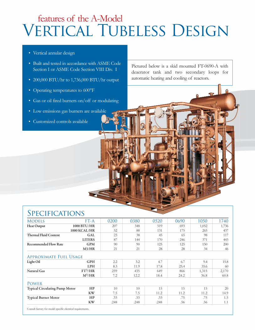
Pictured below is a skid mounted FT-0690-A withdeaerator tank and two secondary loops forautomatic heating and cooling of reactors.
• Vertical annular design
• Built and tested in accordance with ASME CodeSection I or ASME Code Section VIII Div. I
• 200,000 BTU/hr to 1,736,000 BTU/hr output
• Operating temperatures to 600°F
• Gas or oil fired burners on/off or modulating
• Low emissions gas burners are available
• Customized controls available
Vertical Tubeless Design
features of the A-Model
Thermal-bro-053107:Layout 1 6/1/2007 2:55 PM Page 9
Dimensions
Models FT-A 0200 0380 0520 0690 1050 1740
Heater Inlet/Outlet Connections IN 1.5 1.5 2 2 2 2.5MM 38 38 51 51 51 64
(A) Overall Height IN 69 75 85 86 86 110MM 1,752 1,905 2,159 2,185 2,185 2,794
(B) Heater Diameter IN 26 28 30 36 44 44MM 660 710 760 915 1,120 1,120
(C) Overall Depth IN 43 45.5 46 56 64 64MM 1,092 1,156 1,168 1,422 1,626 1,626
(D) Flue Outlet Diameter IN 6 6 8 10 12 12MM 152 152 203 254 305 305
Approx. Dry Weight LB 1,850 2,100 2,300 3,400 4,400 7,200KG 840 955 1,045 1,540 1,995 3,275
Specifications and Dimensions are approximate.We reserve the right to change specifications and/or dimensions without notice.
Operating specifications may change based on field conditions.
D
AB
C
Details
technical
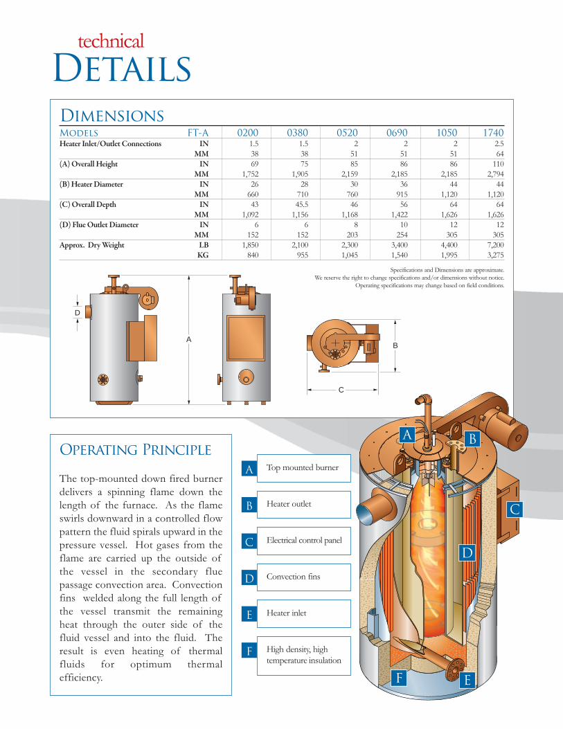
Operating Principle
The top-mounted down fired burnerdelivers a spinning flame down thelength of the furnace. As the flameswirls downward in a controlled flowpattern the fluid spirals upward in thepressure vessel. Hot gases from theflame are carried up the outside ofthe vessel in the secondary fluepassage convection area. Convectionfins welded along the full length ofthe vessel transmit the remainingheat through the outer side of thefluid vessel and into the fluid. Theresult is even heating of thermalfluids for optimum thermalefficiency.
Top mounted burnerA
Heater outletB
Electrical control panelC
Convection finsD
Heater inletE
High density, hightemperature insulation
F
A
E
B
C
F
D
Thermal-bro-053107:Layout 1 6/1/2007 2:55 PM Page 10
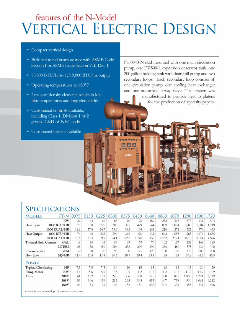
FT-0640-N skid mounted with one main circulationpump, one FT-500-L expansion deaerator tank, one200 gallon holding tank with drain/fill pump and twosecondary loops. Each secondary loop consists ofone circulation pump, one cooling heat exchangerand one automatic 3-way valve. This system was
manufactured to provide heat to platensfor the production of specialty papers.
• Compact vertical design
• Built and tested in accordance with ASME CodeSection I or ASME Code Section VIII Div. I
• 75,000 BTU/hr to 1,719,000 BTU/hr output
• Operating temperatures to 650°F
• Low watt density elements results in lowfilm temperatures and long element life
• Customized controls available,including Class 1, Division 1 or 2groups C&D of NEC code
• Customized heaters available
Specifications
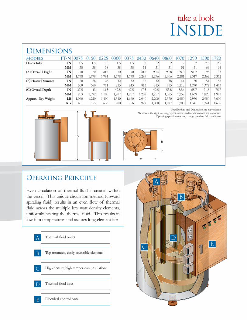
Models FT-N 0075 0150 0225 0300 0375 0430 0640 0860 1070 1290 1500 1720
KW 22 44 66 88 110 126 189 252 315 378 441 504Heat Input 1000 BTU/HR 75 150 225 300 375 429 644 859 1,074 1,289 1,504 1,719
1000 KCAL/HR 18.9 37.8 56.7 75.6 94.5 108 162 216 271 325 379 433Heat Output 1000 BTU/HR 74 148 222 294 368 420 631 842 1,053 1,263 1,474 1,685
1000 KCAL/HR 18.6 37.3 59.9 74.1 92.7 105.8 159 212.2 265.4 318.3 371.4 424.6Thermal Fluid Content GAL 18 36 42 54 63 79 79 102 127 152 168 185
LITERS 68 136 159 204 238 299 299 386 480 575 636 700Recommended GPM 50 50 50 90 90 125 125 150 150 175 200 200Flow Rate M3/HR 11.4 11.4 11.4 20.5 20.5 28.4 28.4 34 34 39.8 45.5 45.5
Power
Typical Circulating HP 7.5 7.5 7.5 10 10 15 15 15 15 15 20 20Pump Motor KW 5.6 5.6 5.6 7.5 7.5 11.2 11.2 11.2 11.2 11.2 14.9 14.9Amps 208V 61 122 183 245 306 350 525 700 875 1,050 1,224 1,399
208V 53 106 159 212 265 303 455 607 758 910 1,061 1,212480V 26 53 79 106 132 151 228 303 379 455 531 606
Consult factory for model specific electrical requirements.
Vertical Electric Design
features of the N-Model
Thermal-bro-053107:Layout 1 6/1/2007 2:55 PM Page 11
Dimensions
Models FT-N 0075 0150 0225 0300 0375 0430 0640 0860 1070 1290 1500 1720
Heater Inlet IN 1.5 1.5 1.5 1.5 1.5 2 2 2 2 2 2.5 2.5MM 38 38 38 38 38 51 51 51 51 51 64 64
(A) Overall Height IN 70 70 70.5 70 70 90.5 90.4 90.8 89.8 91.2 93 93MM 1,778 1,778 1,791 1,778 1,778 2,299 2,296 2,306 2,281 2,317 2,362 2,362
(B) Heater Diameter IN 20 26 28 32 32 32 32 38 44 50 54 58MM 508 660 711 813 813 813 813 965 1,118 1,270 1,372 1,473
(C) Overall Depth IN 37.5 43 43.5 47.5 47.5 47.5 49.5 53.8 58.4 65.7 71.8 75.7MM 953 1,092 1,105 1,207 1,207 1,207 1,257 1,365 1,257 1,669 1,823 1,993
Approx. Dry Weight LB 1,060 1,220 1,400 1,540 1,660 2,040 2,200 2,370 2,650 2,950 2,950 3,600KG 481 555 636 700 756 927 1,000 1,077 1,205 1,341 1,341 1,636
Specifications and Dimensions are approximate.We reserve the right to change specifications and/or dimensions without notice.
Operating specifications may change based on field conditions.
Inside
take a look
B
C
Thermal fluid outletA
Operating Principle
Even circulation of thermal fluid is created withinthe vessel. This unique circulation method (upwardspiraling fluid) results in an even flow of thermalfluid across the multiple low watt density elements,uniformly heating the thermal fluid. This results inlow film temperatures and assures long element life.
Top mounted, easily accessible elementsB
High density, high temperature insulationC
Thermal fluid inletD
Electrical control panelE
E
A
D
C
B
A
Thermal-bro-053107:Layout 1 6/1/2007 2:55 PM Page 12

Shown here is a FT-0600-HC horizontal heater skidmounted with circulation pump and combinationexpansion/deaerator/thermal buffer tank, designedfor barge cargo heating.
• Compact horizontal 3 pass design
• 2,400,000 BTU/hr to 12,000,000 BTU/hr output
• Built and tested in accordance with ASME CodeSection I or ASME Code Section VIII Div. I
• Operating temperatures to 650°F
• Modulating gas, oil or dual fuel burners
• Open protocol burner
• Low profile design
• Customized controls available
Specifications
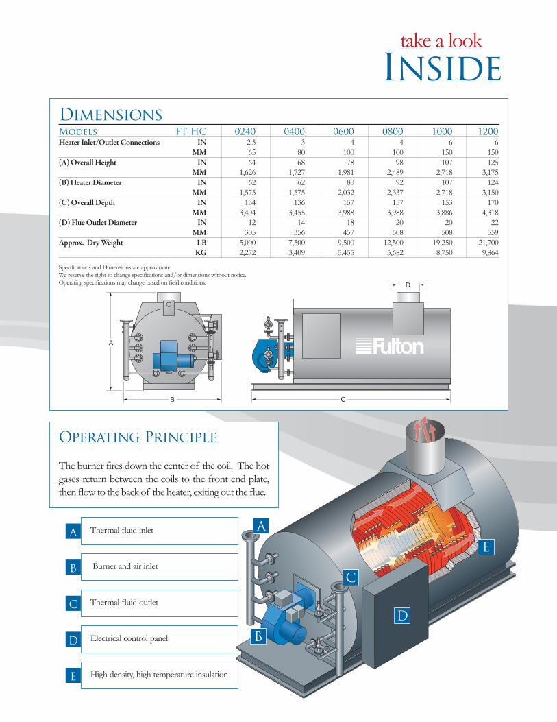
Models FT-HC 0240 0400 0600 0800 1000 1200
Heat Output 1000 BTU/HR 2,400 4,000 6,000 8,000 10,000 12,0001000 KCAL/HR 600 1,000 1,500 2,000 2,500 3,000
Thermal Fluid Content GAL 75 115 190 264 325 508LITERS 284 435 719 998 1,230 1,921
Recommended Flow Rate GPM 150 300 400 600 850 1,000M3/HR 35 69 91 137 193 227
Approximate Fuel Usage
Light Oil GPH 23 39 58 77 96 115LPH 88 148 220 292 364 436
Natural Gas FT3/HR 3,200 5,340 8,000 10,700 13,340 16,000M3/HR 91 152 227 304 378 454
Power
Typical Circulating Pump Motor HP 15 25 30 50 60 75KW 11.2 18.7 22.5 37.3 45 56.3
Typical Burner Motor HP 2 5 7.5 10 15 15KW 1.5 3.7 5.6 7.5 11.2 11.2
Consult factory for model specific electrical requirements.
Horizontal Coil Design
features of the HC-Model
Thermal-bro-053107:Layout 1 6/1/2007 2:56 PM Page 13
Inside
take a look
Dimensions
Models FT-HC 0240 0400 0600 0800 1000 1200
Heater Inlet/Outlet Connections IN 2.5 3 4 4 6 6MM 65 80 100 100 150 150
(A) Overall Height IN 64 68 78 98 107 125MM 1,626 1,727 1,981 2,489 2,718 3,175
(B) Heater Diameter IN 62 62 80 92 107 124MM 1,575 1,575 2,032 2,337 2,718 3,150
(C) Overall Depth IN 134 136 157 157 153 170MM 3,404 3,455 3,988 3,988 3,886 4,318
(D) Flue Outlet Diameter IN 12 14 18 20 20 22MM 305 356 457 508 508 559
Approx. Dry Weight LB 5,000 7,500 9,500 12,500 19,250 21,700KG 2,272 3,409 5,455 5,682 8,750 9,864
Specifications and Dimensions are approximate. We reserve the right to change specifications and/or dimensions without notice.Operating specifications may change based on field conditions.
A
C
D
B
Thermal fluid inletA
Operating Principle
The burner fires down the center of the coil. The hotgases return between the coils to the front end plate,then flow to the back of the heater, exiting out the flue.
Burner and air inletB
Thermal fluid outletC
Electrical control panel D
High density, high temperature insulation E
A
D
B
C
E
Thermal-bro-053107:Layout 1 6/1/2007 2:56 PM Page 14
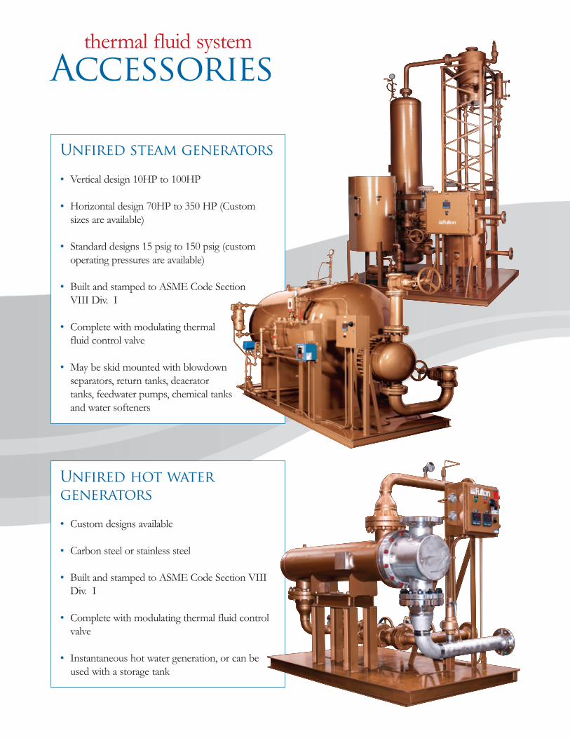
Unfired steam generators
• Vertical design 10HP to 100HP
• Horizontal design 70HP to 350 HP (Customsizes are available)
• Standard designs 15 psig to 150 psig (customoperating pressures are available)
• Built and stamped to ASME Code SectionVIII Div. I
• Complete with modulating thermalfluid control valve
• May be skid mounted with blowdownseparators, return tanks, deaeratortanks, feedwater pumps, chemical tanksand water softeners
Unfired hot water
generators
• Custom designs available
• Carbon steel or stainless steel
• Built and stamped to ASME Code Section VIIIDiv. I
• Complete with modulating thermal fluid controlvalve
• Instantaneous hot water generation, or can beused with a storage tank
Accessories
thermal fluid system
Thermal-bro-053107:Layout 1 6/1/2007 2:56 PM Page 15
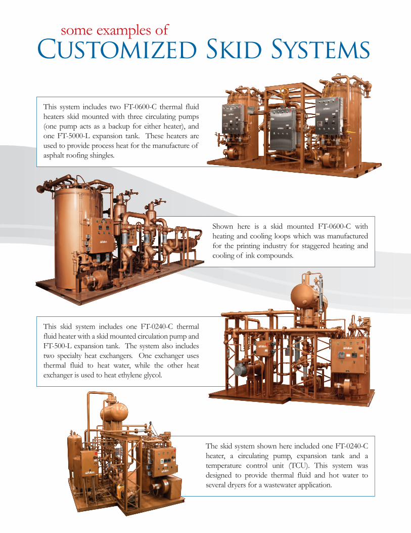
Shown here is a skid mounted FT-0600-C withheating and cooling loops which was manufacturedfor the printing industry for staggered heating andcooling of ink compounds.
This skid system includes one FT-0240-C thermalfluid heater with a skid mounted circulation pump andFT-500-L expansion tank. The system also includestwo specialty heat exchangers. One exchanger usesthermal fluid to heat water, while the other heatexchanger is used to heat ethylene glycol.
This system includes two FT-0600-C thermal fluidheaters skid mounted with three circulating pumps(one pump acts as a backup for either heater), andone FT-5000-L expansion tank. These heaters areused to provide process heat for the manufacture ofasphalt roofing shingles.
The skid system shown here included one FT-0240-Cheater, a circulating pump, expansion tank and atemperature control unit (TCU). This system wasdesigned to provide thermal fluid and hot water toseveral dryers for a wastewater application.
Customized Skid Systems
some examples of
Thermal-bro-053107:Layout 1 6/1/2007 2:56 PM Page 16

www.fulton.com Fulton is a global manufacturer of steam,hot water & thermal fluid heat transfer systems.
FTC BRO053107
Printed in USA
Fulton Thermal Corporation, Inc.
972 Centerville RoadPulaski, NY 13142Call: (315) 298-5121Fax: (315) 298-6390
Thermal-bro-053107:Layout 1 6/1/2007 2:54 PM Page 1


