9 Jin-Hee Song et al. / Procedia Engineering 146 ( 2016 ) 8 – 16
R Difference between long-wave radiation incident on surface from sky and surroundings and radiation emitted by blackbody at outdoor air temperature (W/m2)Solar radiation absorptance of surfaceHemispherical emittance of surface
1. Introduction
To support worldwide reduction in greenhouse gas emissions, the South Korean government reported a policy in 2009 for reducing the annual energy consumption of residential and non-residential buildings by 60% and 30%, respectively, by 2017. The policy also mandated the achievement of zero-energy consumption by 2025. In July 2011, the goal to reduce greenhouse emissions for residential and commercial sectors was set as 26.9% compared to business as usual (BAU). To achieve this goal, a thermal insulation enhancement goal of 20.3% was set for residential and non-residential buildings, and a three-phase thermal insulation enhancement plan for 2015, 2017, and 2019 was announced [1].
Thermal insulation performance of building envelopes has significant effects on the total building energy consumption. The development of a building envelope with high thermal insulation performance is required to meet the goals of the enhanced thermal insulation performance policies. Building envelopes vary according to materials and construction methods. There can be various thermal bridges depending on the envelope type. The actual thermalinsulation performance differs according to the envelope type, even when the same thermal insulation is installed [2].
In this study, thermal bridges of a metal-exterior curtain wall panel system using metal trusses were defined. Then, alternative approaches were proposed for minimizing the thermal bridges. Furthermore, the thermal insulation performances of a conventional panel and its alternatives were evaluated using a three-dimensional transient heat transfer simulation during winter to determine which alternative had the best thermal insulation performance.
2. Thermal bridges of metal-exterior curtain wall panel systems
The metal-exterior curtain wall panel system was constructed by installing vertical and horizontal construction members (such as steel trusses) on the exterior of the structure, attaching exterior materials (such as metal panels), and then filling the vertical and horizontal joints with backup materials and finishing it with a sealant (see Figure 1).The metal-exterior curtain wall panel systems were classified as metal-sheet and metal-panel type, depending on the composition of the exterior material, insulation, and interior material. This study focused on the metal-panel type, in which a metal panel with embedded insulation was installed on the exterior side of the steel truss with an aluminum bracket.
Fig. 1. Metal-exterior curtain wall panel system; (left) construction method, (right) fixing metal panels to metal trusses (1: metal panel, 2: metal
10 Jin-Hee Song et al. / Procedia Engineering 146 ( 2016 ) 8 – 16
Metal panels are manufactured in a factory by covering six sides of the insulation with metal sheets and brought into a construction site in various sizes. They are constructed using the aluminum bracket as shown in Figure 1 (right). In the metal-panel type, vertical and horizontal joints between the panels on the upper/lower/left/right sides are covered with metal and become major thermal bridges going through an insulation layer. Furthermore, various connecting components, such as brackets, bolts, and screws, are installed at repeated intervals. Because such connecting components are made of aluminum or steel, which have high thermal conductivities, the components are considered to be point thermal bridges connected to the major thermal bridges. Figure 2 shows the thermal infrared (IR) image of a building with a metal-exterior curtain wall during winter. As shown in the IR image, heat loss occurs repeatedly through joints between the panels of the building envelopes. Consequently, the actual thermal insulation performance of the building was likely to decrease. Therefore, it was important to minimize the heat loss caused by thermal bridges where joints between panels and connecting components are installed. To this end, three alternatives were selected for the conventional metal panel.
Fig. 2. Thermal IR image from the metal-exterior curtain wall system in winter.
3. Methods
3.1. Evaluation model setup
Figure 3 shows a cross-section of the joints between panels in a conventional metal panel and its three alternatives. The figure includes the cross-section of the aluminum bracket where the panel and the truss are connected. The bracket-fixed metal panel can safely contain high performance insulation such as a vacuum-insulated panel (VIP). It is because of the composition and construction of the bracket-fixed metal panel, in which a metal sheet covers the insulation and the connecting components does not penetrate it, that the performance of these insulation materials is maintained.
(a) Base (b) Alt1 (c) Alt2 (d) Alt3
Fig. 3. Sections of each model with vertical joints between panels.
11 Jin-Hee Song et al. / Procedia Engineering 146 ( 2016 ) 8 – 16
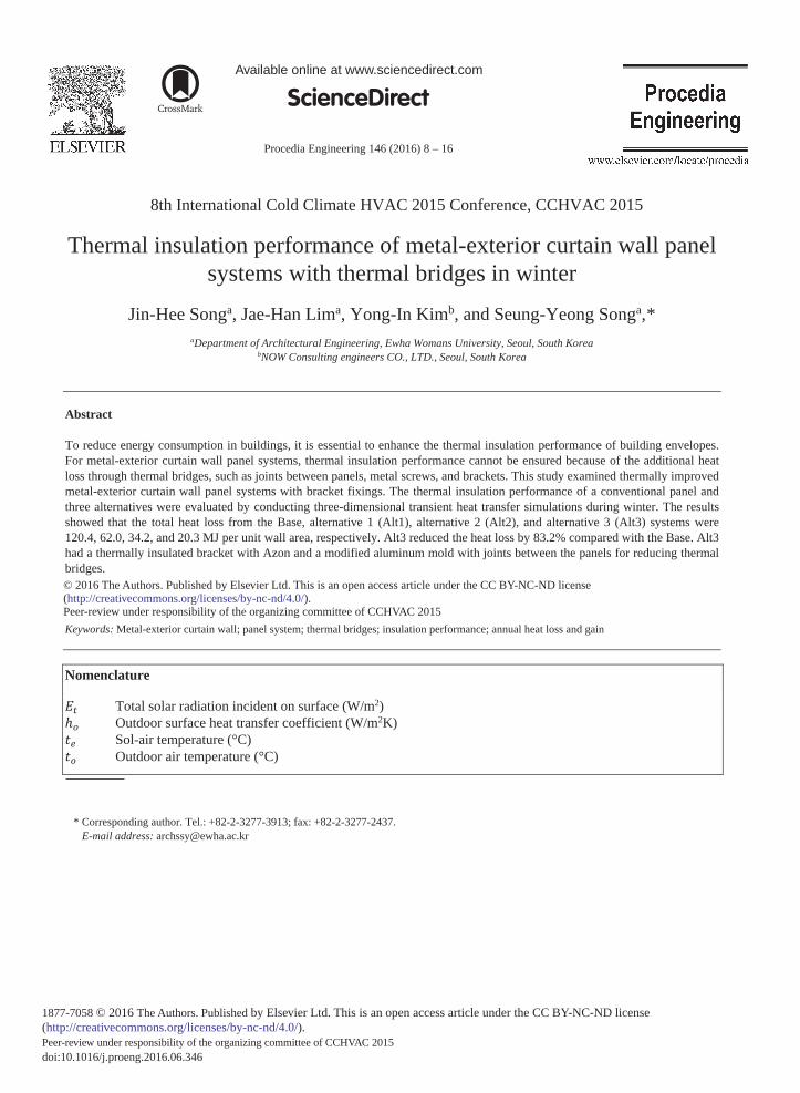
Fig. 4. Thermally insulated bracket with Azon inserted.
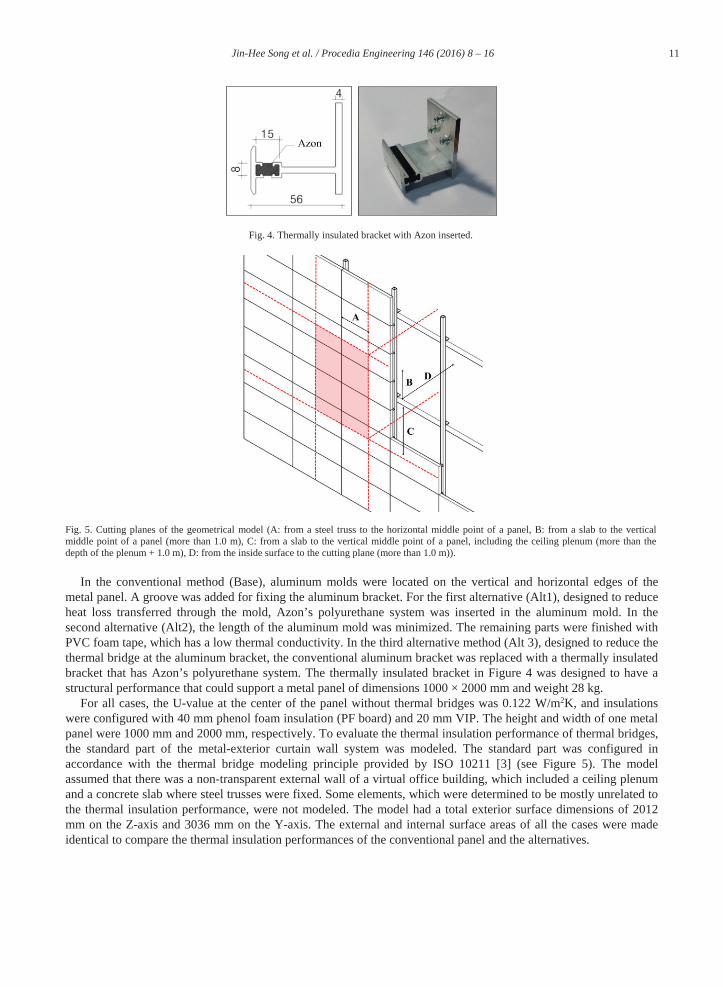
Fig. 5. Cutting planes of the geometrical model (A: from a steel truss to the horizontal middle point of a panel, B: from a slab to the vertical middle point of a panel (more than 1.0 m), C: from a slab to the vertical middle point of a panel, including the ceiling plenum (more than the depth of the plenum + 1.0 m), D: from the inside surface to the cutting plane (more than 1.0 m)).
In the conventional method (Base), aluminum molds were located on the vertical and horizontal edges of the metal panel. A groove was added for fixing the aluminum bracket. For the first alternative (Alt1), designed to reduce heat loss transferred through the mold, Azon’s polyurethane system was inserted in the aluminum mold. In the second alternative (Alt2), the length of the aluminum mold was minimized. The remaining parts were finished with PVC foam tape, which has a low thermal conductivity. In the third alternative method (Alt 3), designed to reduce the thermal bridge at the aluminum bracket, the conventional aluminum bracket was replaced with a thermally insulated bracket that has Azon’s polyurethane system. The thermally insulated bracket in Figure 4 was designed to have a structural performance that could support a metal panel of dimensions 1000 × 2000 mm and weight 28 kg.
For all cases, the U-value at the center of the panel without thermal bridges was 0.122 W/m2K, and insulationswere configured with 40 mm phenol foam insulation (PF board) and 20 mm VIP. The height and width of one metal panel were 1000 mm and 2000 mm, respectively. To evaluate the thermal insulation performance of thermal bridges, the standard part of the metal-exterior curtain wall system was modeled. The standard part was configured inaccordance with the thermal bridge modeling principle provided by ISO 10211 [3] (see Figure 5). The model assumed that there was a non-transparent external wall of a virtual office building, which included a ceiling plenum and a concrete slab where steel trusses were fixed. Some elements, which were determined to be mostly unrelated to the thermal insulation performance, were not modeled. The model had a total exterior surface dimensions of 2012 mm on the Z-axis and 3036 mm on the Y-axis. The external and internal surface areas of all the cases were made identical to compare the thermal insulation performances of the conventional panel and the alternatives.
12 Jin-Hee Song et al. / Procedia Engineering 146 ( 2016 ) 8 – 16
3.2. Overview of the heat transfer simulation
The thermal insulation performance of each alternative was simulated from December to February with a three-dimensional transient heat transfer simulation conducted with Physibel VOLTRA 7.0w [4]. VOLTRA is a commercial and universal heat transfer simulation program developed by Physibel. It is also a highly reliable program capable of precise heat transfer analysis of complex building parts through a heat balance equation with discretization determined using a finite difference method.
The simulation model is shown in Figure 6, and the boundary conditions and material properties of the simulation are described in Figure 7 and Table 1, respectively. The inside air temperature was assumed to be 20 °C, and the surface heat transfer coefficient was 9.09 W/m2K. For the outside condition, the sol-air temperature and a surface heat transfer coefficient dependent on wind speed were used in the calculations. The sol-air temperature was calculated using Equation (1); it is a value determined by combining the outside air temperature with the thermal effects of incident solar radiation, radiant energy exchange with the sky and other outdoor surroundings, and the convective heat exchange with outside air.= + , (1)
where to is the outside air temperature (°C); is the solar absorptance of the surface, defined in [5] as 0.8 for galvanized (weathered) sheet metal; Et is the total solar radiation incident on surface (W/m2); is the hemispherical emittance of the exterior- -wave radiation incident on the surface from the sky and surroundings as well as the radiation emitted by a blackbody at the same outside air temperature (W/m2). Using the outside air temperature and solar radiation data from the Seoul region, South Korea [6], the sol-air temperature was calculated with assumptions about the south-facing vertical wall that are displayed in Figure 7 (left). The outside surface heat transfer coefficient was calculated through a simple algorithm that depended on surface material roughness and surface wind speed [7], the results of which are shown in Figure 7 (right).
Fig. 6. Simulation model in VOLTRA 8.0w.
Table 1 lists the material properties. For the properties of VIP, considering that the size was 1000 × 1000 mm and two sheets of VIP were used per metal panel, the effective thermal conductivity was calculated and applied by considering the linear heat transmission coefficient of the VIP edge [8]. This simulation was performed for 90 days during the winter from December 1 to February 28.
13 Jin-Hee Song et al. / Procedia Engineering 146 ( 2016 ) 8 – 16
Table 2 summarizes the monthly statistics for the outside air temperature, incident solar radiation on the wall surface, and the sol-air temperature during winter. Table 3 gives the heat loss and gain per unit area for each tested alternative. Overall, the heat loss was the maximum in January when the average sol-air temperature was the minimum. At some point during the daytime period, heat gain occurred partially because the outside sol-air temperature became higher than the inside air temperature. Yet, this change accounted for only 3% of heat loss anddeemed insignificant. Given that the sol-air temperature in this paper was calculated by considering a south-facing vertical wall, it can be assumed that for a north-facing vertical wall, for which the effect of solar radiation is relatively small, the heat loss during the day would be higher.
The largest heat loss, 120.4 MJ/m2, was found in the Base. Alt1 showed a heat loss of 62.0 MJ/m2 (a reduction of 48.5%), Alt2 generated a heat loss of 34.2 MJ/m2 (a reduction of 71.6%), and Alt3 displayed a heat loss of 20.3 MJ/m2 (a reduction of 83.2%). For Alt1, the heat loss was reduced because of Azon inserted in the middle of the aluminum mold. However, the linear thermal bridges at the joints between panels were considerable, so the heat loss of Alt1 was still greater than that of Alt2. For Alt2 and Alt3, because the length of the aluminum mold was minimized, the heat loss through the joints between panels was less than that for Alt1. In the case of Alt3, in which a
ThermalConductivity
(W/mK)
Density(kg/m3)
SpecificHeat
(J/kgK)
ThermalConductivity
(W/mK)
Density(kg/m3)
SpecificHeat
(J/kgK)
Concrete a 1.600 2,240 879 Glass woola 0.034 52 657
a: ASHRAE Fundamental, Ch.26 [5]b: ISO 12524[9]c: ISO 10456[10]d: IEA/ECBCS Annex 39[8]
f: Effective thermal transmittance calculated according to IEA/ECBCS Annex 39[8]g: Test results h: Technical report of NORSEAL® [11]i: Heat and Mass Transfer, 2011[12]
14 Jin-Hee Song et al. / Procedia Engineering 146 ( 2016 ) 8 – 16
thermally insulated bracket was used, the heat loss was reduced by 40.8% compared to that of Alt2. Thus, Alt3 was determined to be the alternative that has the highest thermal insulation performance. However, for Alt2 and Alt3, to protect the inside insulation materials from exposure to the outdoors, some further steps must be taken, such as attaching a PVC foam tape during the manufacturing process.
Figure 8 shows the heat loss over a week during each month in winter. In Figure 8, during the night when no solar radiation was present, the heat loss and the differences between Base and three alternatives were very high. In contrast, during the day, when solar radiation is present, heat loss and the differences between the various conditions were considerably lower. Most heat loss in winter occurs in the nighttime because the temperature difference between the outside and inside is large. However, for an accurate heating load evaluation, it would be necessary to consider solar radiation during the daytime. In the case of Alt3, in which thermal bridges were minimized, the difference in heat loss over the week was small and relatively constant.
Table 2. Outside weather conditions during winter.Month Total
Figure 9 shows the outside surface temperature distribution when the lowest outside temperatures occurred during winter. For the Base and Alt1, the heat lost because of the joints between panels was large. Compared to Alt2 and Alt3, it was confirmed that although the heat loss caused by the joints between panels was reduced compared to Alt1, the thermal bridge at the aluminum bracket was highly noticeable. Compared to the heat loss through the linear thermal bridge, where the heat loss ratio was relatively large, the point heat loss was more apparent in the alternativeconditions in which the linear thermal bridge was minimized. In the metal-exterior curtain wall system, a thermally insulated bracket should be considered to minimize this effect.
5. Conclusions
In this paper, a metal-exterior curtain wall panel system was proposed in which the thermal bridge is minimized for enhancing the thermal insulation performance of building envelopes. A three-dimensional transient heat transfer simulation was carried out from December to February using Physibel VOLTRA to evaluate thermal insulation performance.
Three alternatives were proposed to minimize the heat loss through the joints between panels and the aluminum bracket for a conventional metal panel system. In the case of Alt1, Azon’s polyurethane system was inserted in an aluminum mold and the heat loss was reduced by 48.5% compared to the heat loss of the Base. For Alt2, in which
15 Jin-Hee Song et al. / Procedia Engineering 146 ( 2016 ) 8 – 16
the length of the aluminum mold was minimized, a heat loss reduction of 71.6% was obtained. In the case of Alt3, which used a thermally insulated bracket in addition to the conditions of Alt2, the heat loss was reduced by 83.2%. Thus, Alt3 had the best thermal insulation performance. Through comparisons between Alt2 and Alt3, in systems where heat loss from joints between panels was minimized, the heat loss from point thermal bridges at a local fixed point became relatively large. This loss should be prevented.
In the future, the economic efficiency, including energy and initial investment costs, should be determined by conducting simulations to calculate annual heat loss and gain for each alternative method.
Fig. 8. Heat losses during winter.
Fig. 9. Thermal images of the exterior surface (Feb. 23, 4:00 a.m.).
16 Jin-Hee Song et al. / Procedia Engineering 146 ( 2016 ) 8 – 16
Acknowledgements
This research was supported by a KETEP grant (No.20132010101910) funded by the Korea Government and a Residential Environment Research Program grant (16RERP-B082204-03), which was funded by the Ministry of Land, Infrastructure, and Transport of the Korean Government.
References
[1] Ministry of Land, Infrastructure and Transport, Energy Saving Design Reference Notification No. 2014-520, 2014.[2] M.J. Park, J.H. Song, J.H. Lim, S.Y. Song, Needs for Building Envelope Insulation Regulations Reflecting the Thermal Bridging Effects, J.
Archit. Instit. Korea 31(2) 2015 pp.303–pp.312.[3] ISO 10211, Thermal bridges in building construction - Heat flows and surface temperatures - Detailed calculations, 2007.[4] Physibel, Physibel VOLTRA version 7.0w Manual, 2011.[5] ASHRAE, ASHRAE Handbook – Fundamentals, 2009.[6] Korean Solar Energy Society, Weather Data of Seoul Region, 2011.[7] EnergyPlus, EnergyPlus Version 8.1 Documentation, Engineering Reference, 2013.[8] IEA/ECBCS Annex 39, High Performance Thermal Insulation, Vacuum Insulation Panels – Subtask A and B, 2005.[9] BS EN ISO 12524, Building materials and products – Hygrothermal properties - Tabulated design values, 2000.[10] ISO 10456, Building materials and products – Hygrothermal properties – tabulated design values and procedures for determining declared
and design thermal values, 2007.[11] SANIT GOBAIN, NORSEAL® product report.[12] Yunus A. Çengel, Afshin J. Ghajar, HEAT and MASS TRANSFER, 2011.