Northern Innovation Limited have been retained by Invest NI to provide consultancy support to undertake a study on the commercial application of Thermal Oil Technologies in industry that will be published to provide evidence on the deployment of this technology to local businesses.
2.0 Introduction Within Northern Ireland businesses, and SMEs in particular, there is a shortage of specific technical expertise and knowledge in relation to the implementation of energy efficient technologies.
Invest NI’s Sustainable Development initiatives encourage Invest NI Client Companies to reduce costs, innovate and become more competitive by integrating into their core business activities, best practice techniques and/or new technologies relating to energy efficiency, waste management and environmental performance. Occasionally Invest NI undertakes technology studies to encourage best practice and adoption of new technologies to reduce energy costs and minimise waste. The objectives of the Sustainable Development Technology Support in this project is to provide companies with informed technical information on Thermal Oil technologies that use a range of primary fuels along with information on associated costs, so as to identify the optimum circumstances under which to make investment in the technology within their businesses and achieve energy cost savings.
3.0 Terms of Reference
Northern Innovation Limited will be responsible for providing detailed knowledge of this technology in a Report covering the following areas:-
• The report will provide specific advice to enable businesses to make an informed decision for the installation of this technology and to provide background information regarding the use of thermal oils including legislative, insurance and health and safety requirements.
• Identify the types of businesses, processes and premises that may benefit from the deployment of the technology on a cost/energy saving basis for (a) Steam Generation for industrial processes (b) Steam Generation for electricity production (c) Heat Recovery and Heat Transfer (d) other uses for industry identified during the study.
• To investigate the range of fuels to be used to provide the heat input to the thermal oil processes including waste wood, wood chip, wood pellet, oil, natural gas, LPG and excess waste heat including waste to energy plants.
• Provide examples of best technical practice and commercial viability including the optimum operating conditions and the economics of using different fuel types and the effect upon installation costs.
• Provide a detailed case study/scenario for the evaluation of the technical and commercial viability for the installation of a 500kW thermal oil power generation plant demonstrating the savings or otherwise against a conventional power generation plant.
• Identify best practice installations globally for a viable technology model with view to visitation and deployment in Northern Ireland.
4.0 Introduction to Thermal Oils Thermal oils or heat transfer fluids are widely used to carry thermal energy in process heating, metal working and machine cooling applications. They are mainly used in high temperature process applications where the optimum bulk fluid operating temperatures of between 150
ºC and 400
ºC are safer and more efficient than steam, electrical, or direct
fire heating methods. The use of thermal oil systems first started at the end of the 1930s. They were used due to their high energy efficiency and heat transfer rates. However, the oils used were unstable if the temperature increased above the rated stable temperature set-point at regular operating intervals, leading the oil to break down and become partially oxidized and thermally unstable. As a result a number of thermal oil system incidents occurred causing companies to resort back to, what they thought was the safer option, the steam systems. In reality however, thermal oil systems are less complex, easier to design and safer than steam systems provided that are well designed, maintained and the correct fluid for the application has been selected. Since the launch of thermal oil systems, significant advancement in the technology has been made and today thermal oils are much more thermally stable, non-toxic and able to create higher temperatures at atmospheric pressure, than their former counterparts. As a result many companies are investigating the use of the technology in their heat transfer processes. The decision to use thermal oil as a heat transfer medium can be based on many reasons but one of the major incentives is the use on a non-pressurised system. Steam systems operate under pressure and are subject to statutory and regulatory requirements due to the inherent risk from pressure and the increased cost of installation and routine insurance inspection requirements. This report will investigate the opportunities to use Thermal Oil Systems over conventional heat transfer systems and will investigate the design constraints, operational issues and costs of installing a system.
5.0 Thermal Oil Applications The transfer of heat using any fluid can be deemed to be a thermal fluid. Water is the most cost effective and widely used thermal fluid available with high heat transfer efficiencies and easy to control. However, its main limitation is that at a temperature above 100ºC it starts to boil, become steam and hence can only be used as a pressurised system – imposing restrictions upon its handling and use to ensure safe operation. Thermal oils allow the use of low pressure heat transfer systems to achieve high temperatures which would otherwise have necessitated high pressure steam systems. Steam systems are subject to statutory and regulatory requirements due to the inherent risk from pressure and the increased cost of installation and routine insurance inspection requirements.
5.1 Overview Thermal oils as a thermal fluid are used in a variety of applications and industries where high temperatures are required. Some products are used in aerospace, automotive, marine or military applications. Others are used with combustion engines, processing equipment, compressors, piston pumps, gears and final drives. Thermal oils can also be used in food, beverage and pharmaceutical applications. Thermal oil heat transfer systems are used in the following industries:
• Chemical Plants
• Textile Manufacturing Facilities
• Food Processing
• Laundries
• Marine Applications
• Oil and Gas production
• Wood Processing
• Plastic & rubber processing
• Metal, paper and cardboard processing
• Building Materials
5.2 Types of Thermal Oils
There are several types of heat transfer oils available on the market. Circulating coolants, chiller fluids, anti-freezes and refrigerants are used to provide cooling within machinery, process equipment or combustion engines. Hot oils, heater oils and other thermal oils are used to provide or transfer heat to a region near machinery or process equipment. The remainder of the technical investigation in this Report will concentrate on the use of high temperature thermal oils. In summary, high temperature heat transfer oils can be categorized by chemical structure into three primary groups:
• Synthetics
• Hot Oils
• Others including silicones
Figure 1 shows the main heat transfer fluids available and their temperature operating ranges:
Figure 1 – Heat Transfer Fluid Operating Temperature Ranges
Note: Molten salts and liquid sodium are not categorized as thermal oils and therefore shall not be considered for the remainder of the report. They are both heat transfer mediums that can be used in extremely high temperature applications, but they are expensive and are generally only used in specialist applications.
5.2.1 Synthetics The synthetics, also referred to as ‘aromatics’, are man-made fluids, specifically tailored for heat transfer applications. They consist of benzene-based structures and include the diphenyl oxide/biphenyl fluids, the diphenylenthanes, dibenzyltoluenes, and terphenyls. They are formulated from alkaline organic and inorganic compounds and used in diluted form with concentrations ranging from 3% to 10%. There are many advantages of the synthetics over hot oils or non-synthetics including higher temperature and heat transfer, with the synthetic able to obtain safe operating temperatures in the region of 400
ºC, whereas non-synthetics are only thermally stable
up to a maximum temperature of 300ºC. However they are more expensive to buy. As
a general rule, the higher the bulk fluid temperature a fluid is rated the higher the cost of the fluid. The synthetics rated for use above 340
ºC are two to three times more
expensive than the average hot oil rated to 300ºC.
5.2.2 Hot Oils
When crude oil is extracted from the earth it contains a vast mixture of organic compounds, which range from very light hydrocarbons to extremely high molecular weight species. In the refinery the crude oil is distilled and various distillation ‘cuts’ range from light fractions (gas and light solvents), fuel (gas oil), a lube cut, and the heavy tractions (heavy fuel oil and asphalts). Hot oils come from the lube cut and after further refining the hot oils are selected for viscosity (which partly defines the heat transfer properties) and stability, and are branded and marketed as heat transfer fluids.
The overall bulk fluid temperature operating range of petroleum-based fluids is from -20
ºC to just over 300
ºC. Hot oils offer substantial advantages over synthetics in cost,
ease of handling and disposal. In addition, the petroleum-based fluids do not form hazardous degradation by-products and do not have an offensive odour, therefore most spent hot oils can be easily disposed. However, hot oils are less thermally stable at elevated temperatures as they contain a certain degree of un-saturation (double bonds) and being more reactive, chemically than more highly refined petroleum products, are more susceptible to oxidative degradation. 5.2.3 Others including Silicones Silicone-based fluids, and to a larger extent hybrid glycol fluids, are primarily used in specialized applications requiring process/product compatibility. This group’s performance and cost factor disadvantages in the comparative temperature ranges of the synthetics and hot oils make silicone-based and other specialty fluids unlikely choices for most process applications.
5.3 Selecting a Thermal Oil - Design Considerations
Heat transfer fluids and thermal oils vary in terms of kinematic viscosity, operating temperature, pour point, boiling point and flash point and therefore there are many factors to take into consideration when selecting a thermal oil for a heat transfer system. The main ones are listed below. 5.3.1 Safety and Fire Prevention As well as the design features of the system, the thermal oil can greatly influence the fire probability and safety hazard of a heat transfer system. Because thermal oil heating systems include fuel, air and an ignition source, the risk of fire is always present. However, plants can reduce the risk of fire by choosing the correct thermal oil.
When selecting a thermal oil, fire safety is dependent on three measurements, namely flash point, fire point and auto-ignition temperature.
Flash Point – The flash point of a fluid is the temperature at which sufficient vapour is generated for the fluid to flash when exposed to an ignition source. Fire Point – The fire point is the point at which a fluid generates sufficient vapour to support continued combustion. The fire point is typically 5
ºC to 35
ºC hotter than the
fire point. Auto-ignition Temperature – The temperature at which a fluid will ignite without any external source of ignition is the auto-ignition temperature (AIT).
The flash point, fire point and auto-ignition temperature must be interpreted in the context of the actual operating conditions for the thermal oil system. For the vapour to be ignited, the fluid must be at the flash or fire temperature with a source of ignition close enough to the surface to ensure a minimum vapour concentration. In actual conditions, however, leaking oil will cool quickly when exposed to air, dropping below the flash point. The flash and fire point purely provide an indication of the fluid’s volatility or its ability to generate vapour under a given set of conditions. If a significant leak occurs, a fluid with a lower flash point will generate more vapours, creating a greater potential for fire and this ought to be considered when selecting a thermal oil. Although a thermal oil system can operate at a higher flash or fire point of the oil, although not recommended, a system should never run at a temperature in excess of the auto-ignition temperature. The auto-ignition temperature and thermal stability of oil
is the most important factor when selecting the oil and it is essential that the operation temperature of the system is well below the AIT. Relatively few fires have originated in thermal oil systems as a result of the operating conditions exceeding the AIT but this is mainly due to good fluid selection. Most fires that do occur are insulation fires, or are caused by loss of flow, cracked heater tubes or leakage.
5.3.2 Thermal Stability The thermal stability of an oil or fluid is simply defined as the inherent ability of heat transfer oil to withstand molecular cracking from heat stress. Relative thermal stability testing of heat transfer oils measures a particular fluid’s molecular bond strength at a specific temperature versus another particular heat transfer fluid at the same temperature and under identical testing conditions. A fluid’s thermal stability is the primary factor in determining its maximum bulk fluid operating temperature. This is the maximum temperature the oil manufacturer recommends the oil can be used and still maintains an acceptable level of thermal stability. Since fluid degradation rates are closely tied to temperature, continuous use above the manufacturer’s recommended maximum bulk oil operating temperature will increase degradation exponentially. Potential system problems caused by excessive degradation and the subsequent formation of degradation by-products include increased coking and fouling, mechanical difficulties, and decreased heat transfer efficiency. The molecular structures of synthetic heat transfer oils are significantly more thermally stable than the hot oils at temperatures above 300
ºC and therefore are recommended
for elevated temperature processes. Process applications requiring bulk oil temperatures below 300
ºC can specify either synthetic fluids or hot oils. At this
temperature range relative thermal stability data supplied from fluid manufacturers is available to compare individual fluids at specific temperatures. 5.3.3 Heat Transfer Efficiency Heat transfer efficiency comparisons between heat transfer oils are made using heat transfer coefficients. The higher the heat transfer coefficient, the greater the oil’s ability to conduct and transfer heat. At a specific temperature, a fluid’s overall heat transfer coefficient can be calculated using its density, viscosity, thermal conductivity and specific heat at a determined flow velocity and pipe diameter. The resultant heat transfer coefficients may then be evaluated and compared. At a given temperature, the heat transfer coefficients of the fluid types may differ as much as 30%. Depending on the thermal resistance factors of the other components in the system, oil with a substantial heat transfer coefficient advantage may allow a reduction in sizing of system equipment. Replacing existing heat transfer fluid with a more efficient heat fluid may significantly increase production output and/or reduce energy costs. Most of the synthetic oils have a significant advantage in heat transfer efficiency over hot oils from 150
ºC to 260
ºC. Above this temperature range (up to 310ºC) petroleum fluids
narrow the difference somewhat with a select number of highly refined paraffinic/napthenic white oils having a slight efficiency advantage over the mid-range aromatics.
Note: Fluids that have been in service for an extended period of time and has undergone thermal degradation may have a significantly lower coefficient due to fluid viscosity changes and the presence of less efficient fluid degradation by-products.
5.3.4 Kinetic Viscosity Kinematic viscosity is the time required for a fixed amount of fluid or oil to flow through a capillary tube under the force of gravity. It is effectively a measure of fluid’s ability to flow. It is essential that the oil is thin enough to flow through the system whilst still having effective heat transfer. 5.3.5 Pumpability Point
The pumpability point is defined as the temperature at which the viscosity of the fluid reaches a point where centrifugal pumps can no longer circulate the fluid. Although most high temperature process applications run at bulk temperatures well above hot oil and synthetic fluid pumpability points, system designs that might encounter cold weather during emergency shutdowns, maintenance shutdowns, or operate a batch process in a cold climate, should take into consideration pumpability points. In general most of the hot oils offer adequate protection down to -17
ºC whilst the mid-
temperature synthetics (approx 340ºC maximum bulk temperature) offer protection down
to -50ºC. By contrast the high end synthetics, with operating temperature able to reach
400ºC, have a pumpability limit at a temperature of approximately 4
ºC.
5.3.6 Fluid Serviceability
Fluid replacement, reprocessing or filtration may be required from time to time due to unexpected temperature excursions, system upsets, or contamination. Because of the relatively low cost of hot oils (or petroleum-based fluids), very few suppliers offer reprocessing services. Most synthetics are composed of a limited number of aromatic components and have a narrow boiling range, allowing easy identification of degradation by-products and/or contaminants. Reprocessing synthetics using fractional distillation is an economical alternative to disposal and replacement; hence, most synthetic fluid suppliers offer this service at a nominal cost. 5.3.7 Cost As mentioned earlier, the higher the bulk fluid temperature a fluid is rated at, the higher the cost of the fluid. The synthetics rated for use above 340
ºC are two to three times
more expensive than the average hot oil rated to 300ºC, while aromatics rated from
300ºC to 340
ºC are one and a half to two times the cost of the average hot oil.
5.3.8 Disposal and Transport
Petroleum-based fluids offer substantial advantages in ease of handling, reprocessing, shipping and disposal as compared to the synthetics. Also, the petroleum-based fluids do not form hazardous degradation by-products, therefore most spent hot oils can be sent to a local oil/lube recycler for disposal. Finally, the hot oils tend to warrant no special handling precautions and require no special storage requirements. They are extremely user friendly, have a non-discernible odour and are non-toxic both in contact with skin and ingestion. Because of the aromatic-based chemistry of most of the synthetics, some oils can form hazardous degradation by-products that require special permits, handling and shipping precautions. Some synthetics and their vapours may cause skin and eye irritation after prolonged exposure, and emit pungent odours. Since there is a wide range of chemistries available within the aromatic group, not all fluids have similar properties and environmental/personnel concerns and therefore it is important that the best fluid be chosen for the application.
There are thousands of different types and blends of thermal oils on the market. Typically a company markets thermal oil under its own name and does not specify the full blend composition of the products.
The Dow Chemical Company is the largest suppliers of Thermal Fluids in the UK. Table 1 in Appendix 1 provides a list of the company’s DOWTHERM® products, which are a blend of synthetic and organic oils, along with their operating temperatures and technical specifications.
Figure 2 below shows the operating temperature ranges of the DOWTHERM products. The technical specification for each of the oils is shown in Appendix 1.
Figure 2 - Operating temperatures of DOWTHERM Synthetic Organic
Thermal Fluids 5.5 A Comparison: Thermal Fluid versus Steam
As indicated earlier, thermal oil systems have been in use since the 1930s. However, in recent years the use of them has been avoided due to the lack of knowledge and ignorance in the engineering world as to how to design and maintain the systems properly. As a result many heat transfer systems employ the use of steam for heating but in reality there are many reasons why thermal oil systems are superior to steam systems if designed and maintained correctly.
5.5.1 Safety, Environment and Legislative Requirements To deliver the kind of heat required in most process operations, steam systems would have to operate at exceptionally high pressures. At 300
ºC for example, a saturated
steam system needs to be at a pressure of about 110bar. Even at 200ºC the pressure
In contrast, most thermal fluid systems are vented to atmosphere. Pump discharge pressure is just high enough to overcome frictional drag from piping and components while maintaining turbulent flow. There are many advantages to running a system at atmospheric pressure. Systems that run at high pressures require high levels of legislative standards that need to be met. This can be costly and requires specialist engineers that are specially trained to deal with high pressure systems. By contrast, thermal fluid systems have much higher boiling temperatures and therefore operate in their liquid state and hence can be transferred through a facility at atmospheric pressure, making them much less onerous to deal with than steam systems. Therefore, if thermal fluid systems are designed correctly they are safer to run and generally less problematic. 5.5.2 Efficiency Steam systems experience a vast deal of heat losses due to condensation. It is estimated that energy loss due to flash loss (including trap losses) of a typical steam system is in the region of 6% to 14%, 3% loss due to blowdown and another 2% due to de-aerator loss. Thermal oil systems suffer none of these losses and in addition they require less water treatment and are subject to decreased fouling due to considerably lower heat flux. As a result thermal oil systems can be up to 30% more efficient than steam systems, excluding additional heater and steam generator efficiencies. Other energy and maintenance savings are made due to the fact that unlike steam systems, most thermal oil systems operate at atmospheric pressure and are vented to atmosphere at the expansion vessel. As a result pressure in the thermal fluid system is limited to the pump discharge necessary to keep fluid in turbulent flow whilst overcoming piping frictional drag. In steam systems a pressure must be maintained that requires increased pumping energy and hence energy costs. 5.5.3 Corrosion Steam systems are well known for corrosion problems. Air in combination with hot water, salts and other reactive contaminants presents a strong potential for metal corrosion. Steam is abrasive and has virtually no natural lubricity. Add scale and minerals found in most water supplies and the potential for system corrosion increases dramatically. Most synthetics and hot oils used in thermal fluid systems are non-corrosive and provide the same high degree of metal surface protection as light lubricating oils.
5.5.4 Temperature Control Steam systems rely on the control of pressure to control temperature. With this dependence on delicate pressure balance, accuracy is generally limited to swings of ± 6
ºC or so at best. This value may also increase as the system ages and corrosion takes
its toll. Uniformity of heating can also be a problem due to varying rates of condensation and condensate removal in the heat user. In comparison, thermal fluid systems can have an average temperature control of ± 0.8
ºC or less. This precision is accomplished
by the efficient metering and mixing of cooler return fluid with warmer fluid from the supply line. 5.5.5 Environmental Safety The water in a steam system must be chemically treated to reduce corrosion. As a result, steam blowdown and condensate cannot be discharged into sewers, as they present a considerable environmental hazard. Thermal fluid systems require no blowdown and are an entirely closed loop system and therefore do not require any fluid disposal.
5.5.6 Safety To deliver the kind of heat required in most process operations, steam systems would have to operate at exceptionally high pressures. At 300
ºC for example, a saturated
steam system needs to be at a pressure of about 110bar. Even at 200ºC the pressure
still needs to be at 16bar pressure. In contrast, most thermal oil systems are vented to atmosphere. Pump discharge pressure is just high enough to overcome frictional drag from piping and component while maintaining turbulent flow. Therefore, if thermal fluid systems are designed correctly they are safer to run and generally less problematic. 5.5.7 Maintenance Steam systems require constant, unending maintenance that is focused on steam traps, valves, condensate return pumps, expansion joints and water analysis and treatment. Also, when the power fails in cold weather, steam systems are subject to freezing, burst pipes and damaged components. Thermal oil systems require no traps, condensate return, blowdown or water additives and if the proper oil is specified, can be shut down in sub-zero conditions with no worry of freezing. Hot oil systems have proven to operate quietly, safely and efficiently for years with minimal maintenance. 5.5.8 System Cost Purchase cost of steam systems can be less than thermal fluid systems. However, there are paybacks with thermal fluid systems including decreased operating costs, maintenance costs and environmental concerns and increased production and product quality resulting from better control of heating and cooling. Combine these advantages with improved safety and reduced manpower cost and the overall economy of the thermal fluid system will far surpass steam.
6.0 Thermal Oil System Design The use of thermal oil systems is widely used around the world but with reported problems historically due to fires resulting from thermal oil leakages, etc. there has been a fear among many companies of using thermal oil heat transfer systems. However in recent years the introduction of new oils and the associated reduction in the possible risk from combustion has renewed interest in the use of thermal oils.
6.1 Design Considerations
Thermal oil heating systems provide an efficient source of heat for processes that require temperatures as high as 400
ºC. They are often less expensive to operate than
steam systems and usually require less maintenance. In addition, they are more thermally efficient and do not loose heat to the atmosphere through traps and leaks as steam systems do. However, although thermal oil systems are a better all round option for high temperature applications than steam, there are very few systems in operation throughout Northern Ireland. In the past poor design and poor fluid selection has lead to a number of safety incidents leaving a negative opinion on the use of thermal fluids. For this reason management and engineers have avoided the installation of thermal fluid systems in process operations. In reality however, thermal fluid systems are safer than steam systems provided they are designed and maintained correctly. Key to the low cost operation of a thermal oil heater is the simplicity of its design and the safety inherent in its low pressure operation. Figure 3 below is a piping schematic of a typical heat transfer system
Diagram 3 - Typical Thermal Oil Heat Transfer Circuit
The items numbered on Diagram 3 are identified below: (1) Thermal Fluid Heater, (2) Thermal Fluid Circulating Pump, (3) Safety Relief Valve, (4) Thermometer, (5) Pressure Gauge, (6) Thermal Fluid Heated Equipment, (7) Bypass Valve to maintain full flow to heater, (8) Expansion Joints (9) Anchor and Pipe Guides, (10) Expansion Tank, (11) Vent Piping, (12) De-aerator Tank, (13) De-aerator Tank inlet, (14) Thermal Buffer Tank, (15) Catch Tank for drain of pressure relief valve, cold seal, expansion tank, and vent, (16) Gate Valve, (17) Strainer, (18) System Fill Connection, (19) Flexible Connection, (20) Isolating Valve, (21) Manual Low Level Test Line, (22) Manual High Level Test Line. In general a thermal oil system consists of a thermal heater, heat exchanger, vented expansion tank and circulating or system pump. The expansion tank can be purged with an inert gas such as nitrogen to prevent fluid oxidation but in most cases it is vented to atmosphere. From Figure 3 it can be seen that a typical thermal oil system is a closed loop system where heat is transferred from the thermal oil to the process through a heat exchanger. The heat exchanger for a particular process can be in several different forms ranging from a typical plate heat exchanger for fluid to fluid heat transfer or a hot plate for fluid to solid heat transfer etc. The type of heat exchanger chosen for an application is dependent on the process and what the heat is being used for. The heat exchanger design should maximise heat transfer and system efficiency. Key Design Factors There are nine key factors to consider when designing a thermal oil system. Provided these areas are addressed properly, a thermal oil system should operate for many years safely and efficiently.
6.1.1 Heater Sizing and Selection A thermal oil heater should be sized based on the thermal load requirement of the process, the operating temperatures and the flow rate requirements. When calculating the thermal load, heat losses, typically ranging from 10% to 20%, should be allowed. Once the thermal load has been determined, a heater can be selected. Fuel-fired and electric hot oils heaters are available in both vertical and horizontal designs. Coil type thermal fluid heaters offer two-pass, three-pass or four pass models, indicating the number of times combustion gases pass over the coil(s). The designer should consult with the heater manufacturer for the best choice of heater operation based on operating parameters, fuel, footprint and efficiency considerations.
Figure 4 - Thermal Oil Heaters can be Vertical or Horizontal Design
6.1.2 Pump Selection The thermal oil pump is a key part of any thermal oil system. When selecting a pump, the operating temperature, cold start temperature and properties of the thermal oil should all be considered. Pump motors should be selected based on the cold start conditions and the duty required. It is advised to select a seal-less pump with air or water cooling for high temperature thermal fluid systems. 6.1.3 Expansion Tank Size and Selection and Heater Tube Design
Thermal oil expands in volume when heated and this ought to be considered when designing the system. A properly designed hot oil system must include an expansion tank that is sized to accommodate the expanded volume of the system. When selecting a tank, the system volume (including the initial fill of the expansion tank), the operating temperature and the fluid’s coefficient of thermal expansion should all be considered. Because thermal oils expand at different rates, the expansion tank capacity always should be verified against the oil properties prior to filling the system. 6.1.4 Insulation
The relatively few fires that occur in thermal oil systems usually occur in insulation. Insulation fires occur when heat-transfer oil leakage from valves, gaskets, welds or instrument ports infiltrates porous insulation such as calcium silicate or fiberglass wool. The porous insulation’s open structure allows the fluid to flow away from the leak and spread throughout the insulation. Spontaneous ignition may occur if the fluid is suddenly exposed to air if, for example, the protective covering is punctured. The most effective precaution against insulation fires is the identification of all potential leak points and the specification of high-temperature closed-cell insulation or no insulation at these points. Closed-cell insulation prevents the fluid from spreading throughout the insulation. If necessary, flanges should be covered only with metal caps with weep holes - users should avoid insulating these areas if possible. 6.1.5 Piping System When designing the pipework for a thermal oil system, the designer must be certain that the components in the system meet the system’s temperature and pressure requirements. Carbon steel, cast steel, stainless steel and ductile iron are materials suitable for use in hot oil systems. However, brass, bronze, aluminum and cast iron are not acceptable.
Large volume leaks are common in thermal oil systems with badly designed piping systems. Large-volume leaks may be a direct cause of fire if the hot oil contacts an ignition source. Most major leaks result from component failure. Expansion joints, flexible hose and rotary unions are among the components that may fail. There are many ways to prevent leaks, the main ones are:
• Minimize the use of threaded fittings that are unable to cope with the high degree of thermal expansion and contraction in high temperature systems.
• Design the system to allow for adequate thermal expansion and contraction of the piping.
• Design the system to allow expansion joints and flexible hoses to move along their axes, never sideways.
• Install adequate lubrication systems for rotary unions and supply these systems with the correct lubricating oils regularly.
• Install isolation and bleed valves in the piping for each piece of equipment so maintenance can be performed without draining the whole system.
• For valve stems (or ‘packed’ pumps), it is recommended to use packing sets consisting of end rings of braided carbon or graphite fiber, and middle rings of pre-formed (pressed) graphite.
• Use spiral-wound carbon flanges or graphite-filled gaskets
• When installing gasketing, be sure to closely follow the manufacturer’s recommended torquing and tightening sequence. In valves, seat each packing ring fully, and tighten gland nuts slowly while moving the handle back and forth.
• Consider specifying bellows-type valve and seal-less magnetic drive pumps. These will give good performance.
• Install valves with their stems sideways so any leaks run down the steam and away from the piping.
• Ensure that connections larger than 25mm be flanged or welded As part of the commissioning procedure of a thermal oil system, it is strongly recommended that the piping be pneumatically tested for leaks prior to filling the system. This will establish any weak points in the system that requires addressing.
6.1.6 Flow Control Loss of flow occurs when a series of equipment failures interrupts the flow of thermal oil to the heater. A pump motor loss, coupling failure, a system pressure control valve failure or a blinded full-flow filter might cause the initial failure. The second failure then occurs when fouling, burnout or poor location causes the high-temperature cut-off device to miss the sudden temperature increase. As the burner or electrical element continues to put energy into the non-moving fluid, the temperature rises rapidly beyond the auto-ignition temperature. If a crack develops in the heater coil or the piping connected to the heater, hot oil is discharged into the hot atmosphere, where the fluid spontaneously ignites. If the piping remains intact, the vaporized fluid either discharges through a relief valve into the catch tank or pushes fluid up into the expansion tank, which then discharges the fluid into the catch tank. Violent discharges have caused fires when the hot thermal oil vaporized the volatile material in the tank, and the vapour is ignited by the heater. To avoid incidents resulting from the loss of flow, low flow shutdown should be included in the burner safety interlock. Flow detectors that are immersed in the fluid are not recommended because they might fail in the open position. Pressure sensors have proved to be the most reliable for long-term service. To provide effective indication of a no-flow situation, plants can install pressure sensors across a fixed restriction such as an orifice plate or the heater itself to measure pressure drop, or as high and low discharge pump pressure monitors.
6.1.7 Temperature Control
Temperature control requirements dictate system design. Within the modulation range of the burner provided, most heaters can control temperature to ± 3
ºC. If the heater
cycles off, the system could lose up to 28ºC, depending on the system size, quality of
insulation etc. If tighter temperature control is required, a primary/secondary loop system may be employed. With the primary loop operating 13ºC to 28
ºC above the
secondary loop temperatures, even if the heater cycles off, temperature control of ±1.1ºC
may be achieved. The use of primary/secondary loop systems also allows multiple users to operate simultaneously at different supply temperatures. Modulating thermal flow control valves also may be used to control the thermal fluid flow to individual users. However, the supply temperature to each user will be identical unless a primary/secondary loop system is used.
As discussed earlier in the report, the thermal oil selected for an application is extremely important. The thermal oil can influence the safety of the system, the heat transfer, the operating temperature and a whole host of other elements that can determine the design of the system. Therefore the oil manufacturer should have accurate information before selecting an oil and understand the operating conditions. 6.1.9 Electrical Controls The controls chosen for the thermal oil system must comply with HSE standards and therefore depending on the position of control and the contacting material may have to be rated as intrinsically safe. If a place is classified as a place where an explosive atmosphere may occur then it may be seen as a hazardous area and all electrical equipment in it must be rated accordingly.
As well as designing the system to ensure that all electrical equipment complies with HSE standards, it is essential that the control system for the thermal oil system be designed correctly. It is important that all safety interlocks, such as temperature and flow interlocks to shutdown the heater are hardwired into the system and that the appropriate emergency stops are in place. There should be a range of safety interlocks for the system to ensure that the oil temperature does not overheat and become either oxidized or beyond the auto-ignition temperature. Adequate control will also maximize the efficiency of the system and ensure that temperature is maintained. The design of today’s thermal oil systems usually incorporates a PLC for the transfer of data and information. Incorporating a PLC allows the user to sequence controls, view feedback information from the system and to interface with process systems. PLC use for thermal oil systems has allowed tighter control and better information availability on the process operating conditions. In Conclusion: Designing a thermal oil system requires attention to detail as each component of the system is selected. By carefully considering the items outlined above, it is possible to design a system that best meets the heating demands in an efficient, safe, cost effective manner while ensuring the system’s reliability and long-term longevity.
6.2 Operation within a Hazardous Area
If a Thermal Oil System is to be used in a hazardous area, it must be specially designed in order to meet legislative standards. If a place is classified as a place where an explosive atmosphere may occur then it may be seen as a hazardous area and all electrical equipment in it must be rated to Health and Safety Executive (HSE) standards and intrinsically safe. The HSE defines a place where an explosive atmosphere may occur as being: “A place in which an explosive atmosphere may occur in such quantities as to require special precautions to protect the health and safety of the workers concerned is deemed to be hazardous within the meaning of these Regulations” Hazardous places are classified in terms of zones on the basis of the frequency and the duration of the occurrence of an explosive atmosphere. There are three zone categories for flammable vapours and mists, Zone 0, Zone 1 and Zone 2:
Zone 0 - A place in which an explosive atmosphere consisting of a mixture with air of dangerous substances in the form of gas, vapour or mist is present continuously or for long periods or frequently. Zone 1 - A place in which an explosive atmosphere consisting of a mixture with air with dangerous substances in the form of gas, vapour or mist is likely to occur in normal operation occasionally. Zone 2 - A place in which an explosive atmosphere consisting of a mixture with air of dangerous substances in the form of gas, vapour or mist is not likely to occur in normal operation but, if it does occur, will persist for a short period only.
The following categories of equipment must be used in the zones indicated, provided they are suitable for gases, vapours or mists, as appropriate:
4.1 In Zone 0, Category 1 equipment 4.2 In Zone 1, Category 1 or 2 equipment 4.3 In Zone 2, Category 1, 2 or 3 equipment
Where ‘equipment’ means machines, apparatus, fixed or mobile devices, control components and instrumentation which, are intended for the generation, transfer, storage, measurement, control and conversion of energy and the processing of material and which are capable of causing an explosion through their own potential source of ignition. Many Thermal Oil System suppliers can offer flame proof thermal oil heaters that can be used in hazardous industries and in classified zones such as those in the chemical and petrochemical industries.
6.3 System Installation
Proper installation of a thermal fluid system is essential to ensure safe operation. During construction and installation four areas should be addressed: system cleanliness, component orientation, system tightness and allowance for thermal expansion and contraction. 6.3.1 System Cleanliness Care must be taken to assure that the system is clean and dry. Both the ‘hard’ and ‘soft’ contamination is best removed as the system is being assembled. Hard contamination such as mill scale, weld splatter/slag and dirt can cause restrictions that significantly alter fluid flow. Resulting low fluid flow through the heater may cause overheat conditions. Overheating of the fluid can lead to ‘coking’ (carbon deposits in heater tubes), thermal stress on the heater tubing, and possible tubing rupture. Soft contamination such as quench oil, welding flux and protective lacquer coatings can dissolve in the fluid. Carried through the heater, these materials degrade at much lower temperatures than the thermal oil and can form a carbon crust on heated surfaces, particularly on the heater tubing. The coke build-up prevents the fluid from removing heat from the tubing, and results in thermal stress of that tubing.
6.3.2 Component Orientation
Expansion tanks should be located above heaters so that they run at no more than 65ºC
in atmospheric vented systems. Warm-up valves should normally be closed. If run hot,
and in contact with air, the oil can severely oxidize. Valves should be mounted sideward so that leakage from the stem or from bonnet gasketing is less likely to enter insulation. Gaskets should be of the type that can flex with the system’s thermal expansion. Porous insulation should be kept away from potential leak points. 6.3.3 System Tightness
It is strongly recommended that the system be charged with inert gas once construction is completed. This will prevent corrosion and pressure test the system to determine any potential leak points. Furthermore, purging the system prior to thermal oil fill, the dissolved gas will be inert, virtually eliminating start-up oxidation of the heat transfer fluid. 6.3.4 Expansion and Contraction
The average hot oil system experiences wide temperature swings. Metals expand and contract significantly, with different metals expanding and contracting at different rates. If allowances are not made, piping and welds may rupture leading to a shower of hot fluid. The design and installation of the thermal oil system is extremely important to allow for adequate expansion and contraction. Pipe work and equipment should be properly supported, with strong anchors, whilst allowing adequate movement. Bellows can help with expansion and contraction provided that the movement is limited one directional otherwise bellow collapsing can occur. To encourage longitudinal or axial expansion along the pipe work either roller or shoe supports should be used with appropriate support.
6.4 System Maintenance
The proper operation and maintenance of a thermal oil system is the best defense against potential problems. 6.4.1 Fluid Analysis Serious fires caused by cracked heater tubes are relatively rare, but can occur. Cracks are formed by excessive thermal cycling or near hot spots that develop from internal fouling or flame impingement. Leaking fluid will burn off immediately while the heater is operating. However, when the system is not in operation, fluid will continue to leak into the combustion chamber as the result of head pressure from the expansion tank and overhead piping. In the most serious cases, fluid forms in a large pool inside the heater during a prolonged shutdown. When the heater is restarted, the entire pool ignites and destroys the heater. To prevent excessive thermal cycling of heater tube bundle, oversized heaters should be de-rated by the manufacturer. Flame impingement will cause severe thermal cracking of the fluid that can be detected by routine fluid analysis. Heat tube fouling often is caused by deposits that result from fluid oxidation. Oxidation occurs if the expansion tank remains during normal operation and is open to air. The reaction of the hot fluid and air forms tars and sludge that coat surfaces and reduce heat transfer. These deposits could create heater hot spots that ultimately cause cracks. Oxidation can be detected by routine fluid analysis. 6.4.2 System Checks A program of system checks should be completed weekly to check for signs of fluid leakage. Valves, flanges, welds, instrument ports and threaded fittings should be closely observed. A ‘smoking’ system is a strong indication that fluid is leaking.
The system vent should be checked regularly. Mist or steam coming from the vent can signal water in the system or decomposition of the fluid itself. The catch container at the end of the line running from the expansion tank’s relief valve or vent line should also be checked regularly. The catch container should be empty. If it contains liquid, further investigation into why should be investigated. Whilst the potential for fire exists in most plants, strong preventive maintenance programs and common sense can reduce the chance of fire.
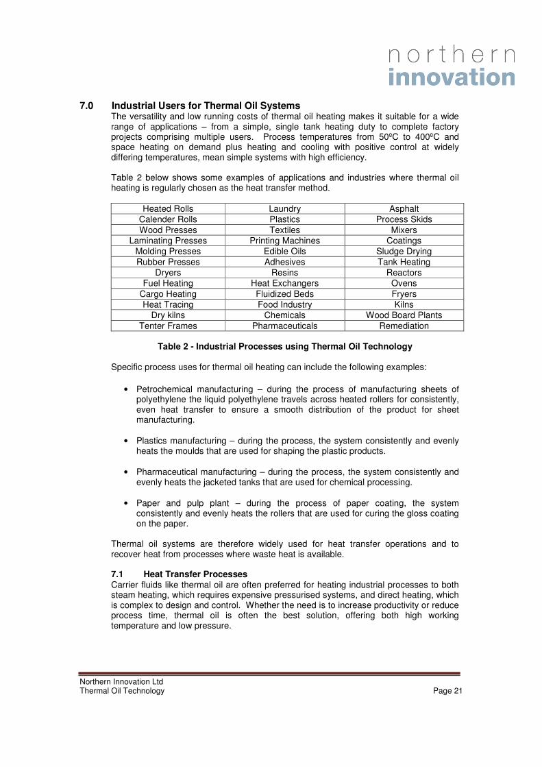
7.0 Industrial Users for Thermal Oil Systems The versatility and low running costs of thermal oil heating makes it suitable for a wide range of applications – from a simple, single tank heating duty to complete factory projects comprising multiple users. Process temperatures from 50ºC to 400ºC and space heating on demand plus heating and cooling with positive control at widely differing temperatures, mean simple systems with high efficiency. Table 2 below shows some examples of applications and industries where thermal oil heating is regularly chosen as the heat transfer method.
Heated Rolls Laundry Asphalt
Calender Rolls Plastics Process Skids
Wood Presses Textiles Mixers
Laminating Presses Printing Machines Coatings
Molding Presses Edible Oils Sludge Drying
Rubber Presses Adhesives Tank Heating
Dryers Resins Reactors
Fuel Heating Heat Exchangers Ovens
Cargo Heating Fluidized Beds Fryers
Heat Tracing Food Industry Kilns
Dry kilns Chemicals Wood Board Plants
Tenter Frames Pharmaceuticals Remediation
Table 2 - Industrial Processes using Thermal Oil Technology
Specific process uses for thermal oil heating can include the following examples:
• Petrochemical manufacturing – during the process of manufacturing sheets of
polyethylene the liquid polyethylene travels across heated rollers for consistently, even heat transfer to ensure a smooth distribution of the product for sheet manufacturing.
• Plastics manufacturing – during the process, the system consistently and evenly heats the moulds that are used for shaping the plastic products.
• Pharmaceutical manufacturing – during the process, the system consistently and evenly heats the jacketed tanks that are used for chemical processing.
• Paper and pulp plant – during the process of paper coating, the system consistently and evenly heats the rollers that are used for curing the gloss coating on the paper.
Thermal oil systems are therefore widely used for heat transfer operations and to recover heat from processes where waste heat is available. 7.1 Heat Transfer Processes
Carrier fluids like thermal oil are often preferred for heating industrial processes to both steam heating, which requires expensive pressurised systems, and direct heating, which is complex to design and control. Whether the need is to increase productivity or reduce process time, thermal oil is often the best solution, offering both high working temperature and low pressure.
With low vapour pressure, moderate viscosity and high thermal stability, thermal oil provides for quick and easy temperature control in operation – a pre-requisite of many processes to ensure uniform heating conditions and product quality.
Owing to its high degree of flexibility, many production technologies developed in the past few decades (e.g. polyester resins, synthetic resins, thermoplastic materials) have been using thermal oil at temperatures even higher than 400°C, in either liquid or vapour phase plants.
Thermal oil heaters are an innovative solution for heat production in those industrial processes where high process temperatures are required. There are many circumstances in which the use of a thermal oil heater rather than a steam boiler is more suitable for heat production, usually due to lower costs.
Figure 5 - Direct Fired Thermal Oil Heater
The thermal oil circulates in a coil heated by the burner flame and its resulting combustion gases. It is then distributed through a low pressure network to the various heat users. On the return circuit a de-aerator/expansion vessel, atmospheric or blanketed with inert gas, ensures the elimination of entrained air, vapour and light fractions before the thermal oil re-enters the heater. Effective fluid expansion and de-aeration systems with thermal buffer are critical for the good, long term operation of a thermal oil system. The primary circulating pump group provides the flow in the system to take the heat from the heater and transfer it to the users. Heat losses are at very low levels of radiated heat from the well insulated distribution pipe work. The heat exchanger can be vertical or horizontal, single pass or multi-pass and any fuel can be used to provide the heat input from gas and oil to biomass products. A major benefit of a thermal oil system is that the circulating hot thermal oil from the heater can be distributed around the main circulation loop and using sub-loops can provide heat to a number of end-users requiring different heat inputs. As shown in Figure 6 below, the ‘cooled’ thermal oil is returned to the heater unit for re-heating. The fuel input to the heater is dependent on the heating load on all of the sub-loop circuits and the end users can be heated rollers, drying plants, small steam
generators, etc. Temperature control is based on blending hot oil with the cooled oil where appropriate.
Figure 6 - Thermal oil from heater can be distributed to a number of end-users
Most thermal oil heaters are supplied as packaged units and the advantages of thermal oil heating systems over conventional steam or direct fired systems are numerous as detailed below.
Figure 7 – Typical Packaged Thermal Oil Heater Units
The main advantages of thermal oil heaters over steam or direct fired are as follows:
• Rapid start-up and shutdown with lowest standing heat losses;
• No boiler blowdown losses, no condensate losses;
• Simple plant design;
• Easy and accurate temperature control;
• Heating and cooling can be undertaken in the same system;
• CO2 and NOX emissions proportionately reduced;
• Mixed temperatures can be easily achieved for different users in a single system
Figure 8 - Thermal oil heater installation
7.2 Thermal Oil Heat Transfer System Installations in the UK Thermal Fluid Systems Ltd are a UK based Company that has over twenty five years experience of designing, supplying and installing Thermal Oil Heating, Cooling and Chilling Systems. During this time, they have supplied equipment for operation at temperatures from -80C to 400ºC and systems with capacities from 30kW to15 MW including installations within the industrial sector in Northern Ireland.
As Agents and Distributors in the UK and Ireland, Thermal Fluid Systems have a long and well established relationship with leading European suppliers of Fired Thermal Oil Heaters. Below are details of typical thermal oil heat transfer installations carried out by Thermal Fluid Systems Ltd for a number of different industries. 7.2.1 Thermal Fluid used in a Foam Production Facility for Autoclave Heating A leading supplier of high quality foam products needed a new thermal fluid installation to provide heating and cooling of various autoclaves operating at medium and very high pressures. The autoclaves requiring heating only had internal coils and relied on natural convection to heat the batches of product arranged on trays in each autoclave. The autoclaves operated at high pressures and heating and cooling of product was achieved by forced convection using nitrogen at high pressures re-circulating via an external heat exchanger. The heating of the re-circulating nitrogen and hence, the processes had
been limited by the maximum temperature which could be achieved using steam heating. At the same time the final cooling of the autoclaves was extended by the compromised design of an external heat exchanger. To achieve the required performance, the thermal oil had to operate at a temperature greater than 300
ºC and cooled to 10
ºC whilst still being capable of effective heat
transfer. Thermal Fluid Systems considered all of the available heat transfer fluids and concluded that the most suitable for this particular application would be DOWTHERM Q. This fluid has been used primarily on pharmaceutical type installations in the range of -20
ºC to
200ºC. The fluid has an atmospheric boiling temperature of 267
ºC and to be able to
operate at the required 300ºC meant the system had to be pressurised. Pressurised
thermal oil systems require careful attention to the design and operation of the pressurising equipment and to the provision of environmentally approved pressure relieving safety devices. The system as installed had two Thermal Fluid Heaters each with dual fuel firing (oil/gas) and rated at 1,700kW intended for normal operation on DOWTHERM Q at 300
ºC but designed for temperatures up to 320
ºC. Each heater has a burner with gas
train, controlled by a sophisticated burner and system management package utilising a PLC Controller and control panel. Fluid circulation in all parts of the plant was achieved by selecting a range of pumps specifically designed for the pumping of heat transfer oils. The pumps were required to handle low viscosity synthetic fluids at high temperatures. Standard type heating/cooling sub-loop packages were provided for those autoclaves which required heating and cooling and these maintain constant flows through the fluid/nitrogen heat exchangers; the re-circulating fluid temperature is varied to suit the process requirements on each autoclave. On each package the fluid was cooled in shell and tube heat exchangers and designed to achieve effective heat transfer at the lowest required processing temperatures.
7.2.2 Thermal Oil use with Heating, Cooling and Chilling in a Hazardous Area
A customer required a flexible heating/cooling/chilling system for a multi-purpose stainless steel reactor, capable of operating with fluid temperatures from -10°C to 240°C. The system supplied was a skid mounted package installed outside the processing area. The system was installed in a Zone 1 hazardous area and the thermal fluid chosen for operation was DOWTHERM Q. The package had a facility for heating the fluid with steam for temperatures up to 150°C plus an electrically heated Thermal Oil Heater for temperatures beyond 150°C up to the maximum of 240°C. Reactor cooling was achieved by constant circulation of the same DOWTHERM Q fluid, which during cooling passed through a first stage cooler using water and, when necessary, there was further cooling of the fluid in a second heat exchanger using a 50% glycol/ water solution at -18°C. The plant has been in operation for nearly five years without any problems, producing a range of products. 7.2.3 Indirect Heating of Process Reactor Vessel in a Hazardous Area For the indirect heating of a process reactor vessel, the customer required heat transfer oil to be available at temperatures up to a maximum of 350°C. Since the installation
required a liquid phase system, rather than design for operation under pressure, it was decided to use a system using Therminol 66 fluid. The 60kW flameproof electrically heated Thermal Oil Heater was specified to operate at up to 350°C and in order to maximise fluid life, the system was provided with a fully modulating control system operated with a high fluid flow rate and was designed for the lowest practical film temperature below the manufacturer's recommended maximum of 375°C. Also, the system was designed with a hot seal pot to allow operation without a nitrogen blanket on the expansion tank. The plant has now been in operation on a continuous basis for over five years without problems and is still using the original charge of Therminol 66 fluid. 7.2.4 Thermal Fluid Systems used for Frying in Food Companies A company produces a range of pre-packaged foods and wished to install a heating system as part of a fast track project to install a new frying line which was to be heated with thermal oil at frying temperatures up to 300°C. The plant was designed to heat up a set of eight cooking pans using a synthetic heat transfer fluid operating at temperatures up to 330°C. The thermal fluid heater includes an automatic start-up facility so that the fluid system reaches the required operating temperature prior to production.
7.2.5 Thermal Fluid System used in a Molding Production Facility
One of the leading suppliers of interior fittings for the motor industry had, for many years, a central heater house with two Thermal Oil Heaters distributing oil around a ring main system to large number of molding presses. While this system was effective it was not very amenable to changes in operating conditions. It was decided that as part of an updating and extension of their facilities to install a number of individual heaters dedicated to particular groups of presses. The company now has three gas fired Thermal Oil Heaters, each rated at 350kW and each feeding fluid to two or three presses. Each heater had Hi/Lo/Off burner control but accurate, consistent molding temperatures were achieved by controlling the flow into the forming tools. The system was designed to provide a high flow of heat transfer oil to each production unit when high heat transfer rates were required. This form of temperature control achieved better response to changes to tool temperatures during the forming operations. The upgrade of the system overall resulted in a more efficient operation and has increased the production output per press. 7.3 Thermal Oil Waste Heat Recovery Processes
Modern boilers, heaters and process heating systems are developed with only modest heat losses. A modern heating plant can have an efficiency of 80% to 90%. This means
the losses - mainly due to chimney loss - of 10% to 20%. By contrast, an older boiler might have heat losses of 30% to 40%. Heat losses can be large even in modern heating plants, when both the amount of loss itself and the amount of loss as it relates to the potential total energy (efficiency) are considered. There are many reasons for this, but common to most existing industrial heating systems is the fact that they originally were designed to the demands present at the time they were erected, and those demands have changed over time. A Waste Heat Recovery Unit (WHRU) is a heat exchanger that recovers heat from a hot gas stream. The hot gas stream can be the exhaust gas from a gas turbine or a diesel engine or a waste gas from an industrial process. The WHRU working medium is frequently thermal oil and the aim of the WHRU is to recover the heat in the waste gas and transfer it to the thermal oil which again is heat exchanged with the final goal fluid.
7.3.1 Typical Sources of Waste Heat The sources of waste heat can be from any industrial process involving heat and Table 3 below identified some where waste heat can be recovered if there is a suitable use on site for its recovery.
High Temperature Heat Recovery
Aluminium Furnace 650 - 750ºC
Steel Handling Furnace 925 - 1050ºC
Cement Kiln 620 - 730ºC
Medium Temperature Heat Recovery
Steam Boiler Exchanger 230 - 480ºC
Gas Turbine 370 - 540ºC
Drying Ovens 230 - 600ºC
Low Temperature Heat Recovery
Recovered Steam Condensate 55 - 88ºC
Injection Moulding Machine 32 - 88ºC
Air Compressor 27 - 50ºC
Table 3 - Possible sources of waste heat for recovery to thermal oil
7.3.2 Design of Waste Heat Recovery Systems Most waste heat recovery systems are designed to fit a specific process requirement. Heat exchangers can be custom engineered to fit the stack, duct, or process line with multiple configurations available to allow for efficient utilisation of the waste energy stream. The finned tube design has a high surface area available which allows for the most economical heat; whereas, the bare tube designs are utilised in gas streams with particulate matter which could foul finned tube exchanger units. Some examples of processes where waste heat can be recovered using thermal oil as the heat transfer medium are listed below:
• Flue gases from fired furnaces and boilers
• Distillation column condensers
• Power generation turbine condensers
• Steam condensate systems
• Incinerators and thermal oxidisers
• Dryers and ovens
• Industrial processes utilising high temperature operations
7.4 Waste Heat Recovery System Installations The recovery of waste heat to thermal oil in industrial processes can be demonstrated by the following examples across a number of sectors as detailed above. 7.4.1 Heat Recovery from incinerators and thermal oxidisers Worldwide, the name Bertrams Heatec is associated with the safe transfer of process heat, particularly in the chemical and petrochemical industries. Most of these production operations require indirect heat transfer, the process heat being conveyed from the fired heater to the process medium (final product) by means of thermal fluid, such as thermal oils. This technique ensures that a flammable end product cannot come into direct contact with the fired heater. In addition, the final product is brought uniformly to the desired process temperature of up to 600ºC without any local overheating. Bertrams manufacture waste heat recovery units in various designs and sizes make it possible to optimize the use of heat in a system. They can be integrated into a complete thermal oil system either as tube coil units or as straight shell-and-tube heat exchangers. These units are installed in tandem with heaters burning fossil or biomass fuels and are used to heat organic thermal fluids or other liquid or gaseous media. Systems in operation include:
• A 4MW waste heat recovery unit with pre-combustion chamber and dual fuel diffusion burner for heating thermal oil
• A 12MW waste heat recovery unit with upstream pre-combustion chamber for heating thermal oil
Bertrams Heatec also incinerates problematic liquids and gases generated in the production of synthetic resins, plastics, artificial fibres, etc. to generate usable process heat. This solution offers two major benefits: emission levels are below the statutory limits, and in many cases substantial savings can be made on primary fuel costs. For many present-day industrial companies the energy factor has an ever increasing impact on profitability and environmental management. Incineration of waste liquids and gases from the production process greatly improves the overall energy balance while minimizing the emissions of pollutants.
7.4.2 Heat Recovery from Fired Furnace Flue Gases and Boilers For most fuel-fired heating equipment, a large amount of the heat supplied is wasted as exhaust or flue gases. In furnaces, air and fuel are mixed and burned to generate heat, some of which is transferred to the heating device and its load. When the heat transfer reaches its practical limit, the spent combustion gases are removed from the furnace via a stack. At this point, these gases still hold considerable thermal energy. In many systems, this is the greatest single heat loss and the energy efficiency can often be increased by using waste heat gas recovery systems to capture and use some of the energy in the flue gas. The use of a heat exchanger in the flue to remove heat from the combustion gases and transfer it to the thermal oil allows this recovered heat to be used elsewhere to pre-heat the fuel, combustion air or other processes to reduce energy usage. The temperature of exhaust gases can be as high as 400 - 600 °C, even after heat has been recovered from it for preheating the charge or combustion air. One possibility is to install a waste heat boiler to produce steam or hot water from the recovered heat in the thermal oil, especially when large quantities steam or hot water are needed in a plant. Sometimes the recovered exhaust gas heat can be used for heating purposes in other equipment, but only if the heat quantity, temperature range, operation time etc are suitable for this. Benefits of waste heat recovery include:
• Improved heating system efficiency. Energy consumption can typically be reduced by 5% to 30%
• Lower flue gas temperature in chimney so less heat is wasted.
• Higher flame temperatures. Combustion air preheating heats furnaces better and faster.
• Faster furnace start-up. Combustion air preheating heats furnaces faster.
• Increased productivity. Waste heat used for load preheating can increase throughput.
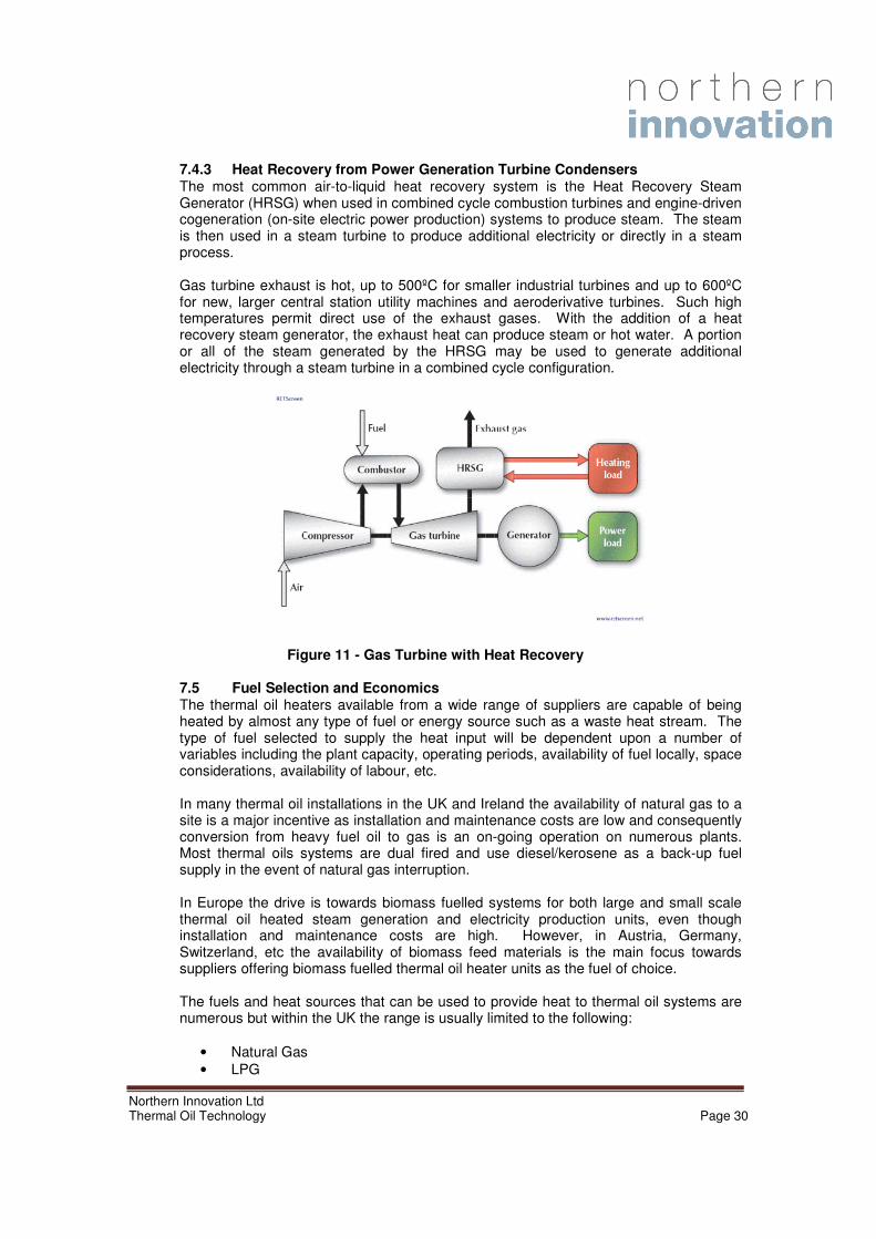
7.4.3 Heat Recovery from Power Generation Turbine Condensers The most common air-to-liquid heat recovery system is the Heat Recovery Steam Generator (HRSG) when used in combined cycle combustion turbines and engine-driven cogeneration (on-site electric power production) systems to produce steam. The steam is then used in a steam turbine to produce additional electricity or directly in a steam process. Gas turbine exhaust is hot, up to 500ºC for smaller industrial turbines and up to 600ºC for new, larger central station utility machines and aeroderivative turbines. Such high temperatures permit direct use of the exhaust gases. With the addition of a heat recovery steam generator, the exhaust heat can produce steam or hot water. A portion or all of the steam generated by the HRSG may be used to generate additional electricity through a steam turbine in a combined cycle configuration.
Figure 11 - Gas Turbine with Heat Recovery
7.5 Fuel Selection and Economics The thermal oil heaters available from a wide range of suppliers are capable of being heated by almost any type of fuel or energy source such as a waste heat stream. The type of fuel selected to supply the heat input will be dependent upon a number of variables including the plant capacity, operating periods, availability of fuel locally, space considerations, availability of labour, etc. In many thermal oil installations in the UK and Ireland the availability of natural gas to a site is a major incentive as installation and maintenance costs are low and consequently conversion from heavy fuel oil to gas is an on-going operation on numerous plants. Most thermal oils systems are dual fired and use diesel/kerosene as a back-up fuel supply in the event of natural gas interruption. In Europe the drive is towards biomass fuelled systems for both large and small scale thermal oil heated steam generation and electricity production units, even though installation and maintenance costs are high. However, in Austria, Germany, Switzerland, etc the availability of biomass feed materials is the main focus towards suppliers offering biomass fuelled thermal oil heater units as the fuel of choice.
The fuels and heat sources that can be used to provide heat to thermal oil systems are numerous but within the UK the range is usually limited to the following:
• Waste heat recovery (waste to energy) To evaluate the benefits of each fuel type for use on a thermal oil system it is necessary to determine the energy content and cost of each fuel to allow the economics of each to be assessed against the projected installation costs. 7.5.1 Fuel Energy Content and Costs Different energy sources are measured in different units and make it difficult to compare the actual costs for powering a heating system between different energy sources. For this reason standardised units and costs are used. In making these calculations particular sources of data and assumptions have been used. Prices change constantly and the analysis has therefore been undertaken based on March 2010 costs. Tables 4 & 5 below details typical fuel costs (March 2010) and energy content of each of the selected fuel types:
Table 4 – Thermal and Energy Properties of a Range of Fuels
Fuel Price per unit kWh per unit pence per kWh
Wood chips (30% MC) £80 per tonne 3.5 kWh/kg 2.3p/kWh
Waste Wood (dry) £35 per tonne 3.5 kWh/kg 1.0p/kWh
Wood pellets £185 per tonne 4.8 kWh/kg 3.9p/kWh
Natural gas 4.1p/kWh 1 4.1p/kWh
Heating oil 44p per litre 10 kWh/litre 4.4p/kWh
LPG (bulk) 40p per litre 6.6 kWh/litre 6.1p/kWh
Waste Heat 0.0p/kWh Variable 0.0p/kWh
Table 5 – Typical Fuel Costs and Energy Contents
Note: Data based on March 2010 and sourced from Nottingham Energy Partnership
All prices are prone to significant variation with geographical region, order quantities, overall contract size and duration, time of year, delivery distance and time, etc. Wood fuels in particular are available at prices both significantly above and below those quoted, and bulk prices will be subject to a minimum delivery size of perhaps 3 - 5 tonnes. Wood pellets bought in bags may be significantly more expensive than those bought in bulk.
Waste heat is an option where there is an available supply and in the case of electricity production using steam turbines, waste heat is always a subsidiary product of the process that can be utilised effectively in heating applications. As a waste product it has been assumed that the procurement cost of the heat would be zero.
Using the information in Table 5 above the cost of operating a thermal oil heater unit can be assessed for each of the fuel types based on projected boiler combustion efficiencies. In Table 6 below the cost per MWh of heat input for each fuel has been calculated.
Fuel Boiler Efficiency
(%)
Energy Cost
pence per kWh
Fuel Cost
per MWh
Wood chips (30% MC) 80 2.3p/kWh £28.75
Waste Wood (dry) 80 1.0p/kWh £12.50
Wood pellets 90 3.9p/kWh £43.33
Natural gas 90 4.1p/kWh £45.55
Heating oil 90 4.4p/kWh £48.88
LPG (bulk) 90 6.1p/kWh £67.77
Waste Heat n/a 0.0p/kWh £0.0
Table 6 - Energy Cost per MWh for a Thermal Oil Heater Unit
The table above shows that biomass materials such as wood chips and waste wood are the most cost effective fuel to be used per MWh of heat output from a thermal oil heater unit. Wood pellets are fifty percent more expensive than wood chips but at this time there is a trend towards natural gas and pellets becoming similar in cost. The simplicity and reduced capital cost of installing a natural gas supply to fuel a thermal oil plant as compared to a biomass wood pellet supply plant would be difficult to justify at this time. However, fuel cost trends should be considered when deciding upon the fuel to be selected.
In Figure 12 below the variations in fuel costs over the period 1999 to 2008 has been identified and shows that oil and propane have increased dramatically during that period with some reduction in the past few years from peaks in 2007. However, natural gas and wood pellets have both risen by 91% and 69% respectively in this period.
Figure 12 – Fuel Cost Trends over the period 1999 to 2008
Based upon the current continuing high cost of fuel in 2010 there is no reason to expect that fuel costs will not continue to dramatically increase in the future.
The assessment of the fuel costs at 2010 prices would indicate that if wood chips were available in sufficient quantity to meet the thermal oil heater demands and space existed to store the product on-site, etc. the cost per MWh of heat input would be very attractive. However, the additional cost of the biomass storage, materials handling and ash removal equipment, etc. coupled with on-going maintenance costs, would require a thorough investigation to assess the true operating cost of each project based on the overall capital expenditure. Natural gas is the preferred fuel option for use on a thermal oil heater unit in terms of simplicity of operation, minimal maintenance costs, temperature control accuracy and low installation cost, etc. In the UK and Ireland natural gas is the fuel of choice in the vast majority of existing and new thermal oil installations. This is closely followed by heavy fuel oil/diesel installations which are being converted to natural gas as the gas supply becomes available in the location. Little use has been made of biomass as the fuel of choice due to its limited availability and projected capital expenditure cost of the biomass storage and combustion system.
8.0 Steam Generation for Industrial Processes The vast majority of high pressure steam generation plants are fuelled by gas or oil. This is based on the simplicity of operation and the minimisation of expensive ancillary services. However, in some circumstances it is possible to generate high pressure steam using thermal oil as the heat transfer medium to boil the water. The systems are generally referred to an indirect or unfired steam generators or a thermal oil boiler. 8.1 Indirect Steam Generators using Thermal Oil
Thermal oil as the main medium for steam or superheated water generation has achieved success in some industrial applications with limited steam capacities. This solution was successful because in some cases it is the most cost-effective.
Some circumstances make this kind of steam generation an ideal solution:
• In some countries the law requires the continuous supervision of qualified staff for conventional steam boilers. In the case of indirect steam production this supervision is not needed.
• In the processes or plants where hot thermal oil and steam are both needed. In these cases the indirect steam generation provides heat and steam with a single solution.
Numerous suppliers offer an ‘unfired steam generator’ plant and the principle of operation is relatively straightforward as shown in the diagram below. The thermal oil boiler heats the thermal oil which circulates through the steam kettle/drum and transfers heat to water to produce steam at the desired rate. Process control systems are installed to regulate the steam pressure based on usage rates and the temperature and flowrate of thermal oil is automatically adjusted to maintain the steam requirements. Using a kettle type heat exchange (oil/steam) it is possible to produce steam up to 25barg.
Figure 13 - Typical Un-fired Steam Generation Process
INTEC Engineering GmbH is an international company recognised for the design, manufacturing and delivery of energy systems. INTEC-plants universally use thermal oil as the heat transfer medium. The figure below shows a typical thermal oil steam generator for use on a MDP Plant where steam at 16barg was required at 15t/hr.
As indicated earlier, a major advantage of a single fired thermal oil heater is the potential to utilise high temperature (thermal oil) and medium to low temperature (using steam) in the same industrial process using a range of applications. One industry where this is widely used is in large laundries for cleaning and preparing textiles.
For decades high pressure steam was used for the heating of the various machines operating in the laundries. Until recently, for large laundries, the high-pressure steam plant was unchallenged and popular everywhere. But there were disadvantages that had to be taken into account and were unavoidable when using high pressure steam:
• Potential danger of high pressure steam processes to operatives
• Expensive water treatment facilities
• Statutory inspection obligations with associated costs
• Chemical consumption and handling
• Daily maintenance works
• Condensate and energy losses
• Corrosion problems
A number of companies specialise in the supply of thermal oil steam generation plants for the laundry industry including Regiomat AG. Their systems are designed to allow the thermal oil heater system to be used to supply heat to the processes using thermal oil as the heat transfer medium and to also provide steam for those plants that need steam only. The advantages of using a thermal oil heating plant to a laundry owner are as follows:
• Efficient heating of dryers and ironers
• Washing machines can be connected directly to the thermal oil installation
• Washing machines can be connected with a steam generator of only 4bar without any condensate recycling
• Easy starting after long breaks as the thermal oil system is always filled with thermal oil which protects the installation against corrosion problems
• Less apparatus required in comparison with a steam heating system and investment costs approximately 30 - 40 % lower
A typical thermal oil heating and steam generation plant for a laundry process is shown below in Figures 15 and 16. In Figure 15 the thermal oil heater unit provides a thermal oil circuit with oil at a temperature of 300ºC. The oil is used in the circuit to provide heat to the washer extractor, dryer and ironer with flow control vales installed on each machine to regulate the oil flowrate and maintain the desired temperature at each end-user. In Figure 16 the circuit extends to provide heat to two steam generators used to provide low pressure steam to a second washer extractor and tunnel washer on one circuit with a second steam generator supplying steam to a dedicated ironer unit.
9.0 Steam Generation for Electricity Production using Thermal Oil Power generation by combustion can be divided into closed thermal cycles and open processes. Open cycles are used for gaseous and liquid fuels to drive internal combustion engines and gas turbines. The fuel is burnt either directly inside an internal combustion engine or in a combustion chamber and then led through an open gas turbine for expansion. In closed thermal cycles, the combustion of the fuel and the power generation cycle are separated by a heat transfer from the hot combustion gas to a process medium used in a secondary cycle. By this separation between fuel and engine, the engine is in contact with a clean process medium. Hence undesired elements in the fuel and flue gas do not cause damage to the engine. Steam generation from thermal oil to produce electricity is not widely used in the UK but is becoming much more popular in Europe for small scale electricity users, especially when using biomass as the fuel source. The conventional method of producing electricity from steam is via a steam turbine using the Steam Rankine Cycle (SRC) and a range of fuel types. However, using thermal oil to provide the heat to the system involves the use of an Organic Rankine Cycle (ORC) which uses a high molecular weight organic fluid rather than steam to generate the electricity in the turbine. 9.1 Electricity Production Plants using Steam Rankine Cycle
Electrical energy generation using conventional steam turbines involves three energy conversions, extracting thermal energy from the fuel and using it to raise steam, converting the thermal energy of the steam into kinetic energy in the turbine and using a rotary generator to convert the turbine's mechanical energy into electrical energy.
Figure 18 - Conventional Steam Turbine Process
Steam is mostly raised from fossil fuel sources, three of which are shown in the above diagram but any convenient source of heat can be used. In fossil fuelled plants, steam is raised by burning fuel, mostly coal but also oil and gas, in a combustion chamber. Recently these fuels have been supplemented by limited amounts of renewable biofuels, biomass and agricultural waste.
The chemical process of burning the fuel releases heat. There will be losses due to impurities in the fuel, incomplete combustion and heat and pressure losses in the combustion chamber and boiler. Typically these losses would amount to about 10% of the available energy in the fuel.
High pressure steam is fed to the turbine and passes along the machine axis through multiple rows of alternately fixed and moving blades. From the steam inlet port of the
turbine towards the exhaust point, the blades and the turbine cavity are progressively larger to allow for the expansion of the steam.
The stationary blades act as nozzles in which the steam expands and emerges at an increased speed but lower pressure. As the steam impacts on the moving blades it imparts some of its kinetic energy to the moving blades.
The exhaust steam from the low pressure turbine is condensed to water in the cooling system. The volume of the steam goes to zero in the condenser, reducing the pressure to near vacuum conditions thus increasing the pressure drop across the turbine which enables the maximum amount of energy to be extracted from the steam. The condensate is then pumped back into the boiler as feed-water to be used again.
Steam turbines typically have a thermal efficiency of about 35%, meaning that 35% of the heat of combustion is transformed into electricity. The remaining 65% of the heat either goes up the stack (typically 10%) or is discharged with the condenser cooling water (typically 55%).
Steam turbine systems are essentially heat engines for converting heat energy into mechanical energy by alternately vaporising and condensing a working fluid in a process in a closed system known as the Steam Rankine Cycle (SRC). This is a reversible thermodynamic cycle in which heat is applied to a working fluid in an evaporator, first to vaporise it, then to increase its temperature and pressure. The high temperature vapour is then fed through a heat engine, in this case a turbine, where it imparts its energy to the rotor blades causing the rotor to turn due to the expansion of the vapour as its pressure and temperature drops. The vapour leaving the turbine is then condensed and pumped back in liquid form as feed to the evaporator.
In this case the working fluid is water and the vapour is steam but the principle applies to other working fluids which may be used in low temperature applications. The working fluid in a Rankine cycle thus follows a closed loop and is re-used constantly. 9.2 Electricity Production Plants using Organic Rankine Cycle The Organic Rankine Cycle (ORC) is very similar to the Steam Rankine Cycle except steam is substituted with a high molecular weight organic fluid. The selection of a suitable organic fluid is not easy as each organic fluid has its own specific properties and not every fluid can be used in a certain application. Depending on the type of heat source and the temperature level, a suitable organic fluid with appropriate evaporation and condensing temperatures has to be selected. Working fluids suitable for the proposed cycle can be found in the class of organics, in particular among the newly developed, zero ozone depletion potential, chlorine-free compounds. The numerous technical and environmental requirements which a fluid must meet for practical use combined with the peculiar thermodynamic restraints limit the number of suitable fluids. Examples include toluene, isopentane, isooctane, polysiloxane oil, etc. The main difference between organic fluids and water is the lower evaporation energy of the former, so less heat is needed to evaporate the organic fluid. The evaporation of organic fluids usually takes place at lower temperature and pressure and the thermodynamic and chemical characteristics of these fluids no longer require superheating.
The fuel used to heat the thermal oil can be any of the standard fossil fuels together with the combustion of biomass products and agri-waste materials, etc. The ORC process is especially suited for electrical power production based on industrial waste heat even at temperatures as low as 100ºC. In order to produce electricity, waste heat is transferred to the thermal oil cycle and further on to the ORC unit by heat exchangers. The ORC unit produces electrical energy which could be used to cover the auxiliary power demand of the manufacturing plant or for the feed-in into the public grid. Additionally, the ORC unit produces low temperature heat. Depending on the site constraints of the manufacturing plant the low temperature heat can be used as low temperature process heat (e.g. drying), for the internal space heat supply or external
heat consumers (e.g. via a district heating system). The working principle and the different components of the ORC process are shown in Figure 19 below. The ORC process is connected with the thermal oil boiler via a thermal oil cycle. The ORC unit itself operates as a completely closed process utilising a specific organic fluid as the organic working medium. This pressurised organic working medium is vaporised and slightly superheated by the thermal oil in the evaporator and then expanded in an axial turbine which is directly connected to an asynchronous generator. Subsequently, the expanded organic fluid passes through a regenerator (where in-cycle heat recuperation takes place) before it enters the condenser.
Figure 19 - Principle of co-generation with an ORC process Items identified in Figure 19 above are as detailed below:
Item 1 Regenerator Item 2 Condenser Item 3 Turbine Item 4 Electric generator Item 5 Circulation pump Item 6 Pre-heater Item 7 Evaporator Items 8 & 9 Hot water inlet and outlet Items 10 & 11 Thermal oil inlet and outlet
9.3 Typical Examples of ORC Electricity Production Plants
There are a number of companies that specialise in ORC plants and two are identified below.
9.3.1 Turboden S.r.l Based in Northern Italy, Turboden S.r.l specialises in the applications of Organic Rankine Cycle technology. Since 1980 Turboden has focused its activity on the design and the production of ORC systems for distributed generation in renewable energy applications and industrial heat recovery. To date the company has 140 plants in operation across twelve countries in Europe with the vast majority operating on biomass as the fuel supply. The Company’s main application fields include:
• Biomass cogeneration for district-heating or for sawmills and pellet manufacturing companies;
• Waste heat recovery: Electrical energy production from exhaust streams in industrial processes;
• Small combined cycles: Electrical energy production from residual heat of internal combustion engines, or gas turbines;
• Solar thermodynamic conversion: electrical energy production from medium high temperature solar collectors.
Turboden ORC units are typically up to 2MW electrical per unit. Larger installations can be obtained by coupling a number of units – 10MW is practical using 5No units.
The key component in a biomass co-generation system is the ORC turbo generator that yields electricity generation with good efficiency and reliability from thermal oil at the relatively low temperature of 300ºC. The unit is based on a closed Rankine cycle adopting a suitable organic fluid as the working fluid.
Figures 20 and 21 below show typical schematics of a closed loop system.
Figure 21 - Simplified Schematic diagram of an ORC Unit
The turbo generator uses the hot temperature thermal oil to pre-heat and vaporise a suitable working fluid in the evaporator (8 - 3 - 4). The organic fluid vapour powers the turbine (4 – 5) which is directly coupled to the electric generator through the coupling. The exhaust vapour flows through the regenerator (5 – 9), where it heats the organic liquid (2 – 8). The vapour is then condensed in the condenser (cooled by the water flow) (9 – 6 – 1). The organic fluid is finally pumped (1 – 2) to the regenerator and then to the evaporator, thus completing the sequence of operations in the closed-loop circuit. Compared to competing technologies, the main advantages of the ORC process are as follows:
• High cycle efficiency
• Extreme high efficiency of the turbine (up to 85%)
• Low mechanical stress for the turbine due to low speed design
• The low speed allows the direct coupling of the generator without a gearbox
• Automatic start-up and shut-down operation
• Fully automatic operation with low maintenance and operational costs
• No corrosion problem due to the non-corrosive organic fluid
• No erosion problems of the turbine blades due to "dry" vapour phase
• Low noise emissions.
Figure 22 - Layout of a Turboden 10 ORC Unit (1MWel)
Turboden supply a range of ORC plants ranging in electrical output from 400kWel to 2.2MWel. Each unit is designed to be skid mounted and is connected directly to the thermal oil boiler or heat recovery source. 9.3.2 Mawera GmbH Thermal oil is heated in a Mawera thermal oil boiler to 300ºC and fed into an ORC turbine. The organic fluid is vaporised and drives a slow running axial turbine, generating mechanical work as it expands into the vacuum, which in turn generates electrical energy in the generator coupled directly to the turbine. The expanded vapour is directed towards a regenerator for heat recovery purposes, which increases the electrical efficiency rate. The fluid vapour enters the condenser and the condensate is pumped back to the required operating pressure and directed into the vaporiser. The ORC is a closed loop cycle. Mawera plant capacities range from 0.3MW to 1.5MW electrical output.
10.0 Case Study – 500kW Thermal Oil Power Generation Plant To assist in evaluating the use of thermal oil technology in an electrical power generation plant, a case study of the technical and commercial viability for the installation of a small-scale 500kW thermal oil power generation plant will be undertaken. This will demonstrate the savings against a conventional power generation plant supplied by different primary fuels and the commercial viability at present energy costs. 10.1 Introduction
The whole world is aware of the fact that fossil fuel supply is limited and further exploration will involve more expensive fuels. In addition, emissions from fossil fuels generate billions of tons of CO2 each year, which is the main cause of global warming and environmental changes. The long term impact of these negative developments can still not be predicted in detail and many international operating associations have highlighted these problems over decades and there are bonus systems in place to counteract and to persuade industry to invest in “renewable energy”. The cycle of usage and production of biomass as a renewable energy is balanced. Biomass can be produced almost everywhere and has several environmental advantages over fossil fuels. The main advantage is that biomass is a renewable resource, offering a sustainable, dependable supply. Other advantages include the fact that the amount of carbon dioxide (CO2) emitted during the combustion process is typically 90% less than when burning fossil fuel. Biomass fuel contains minimal amounts of sulphur and heavy metals. It is not a threat to acid rain pollution, and particulate emissions are controllable. The production of electrical energy from biomass has a higher importance than producing heat from biomass. Electricity can be supplied over distances with very little loss and can be sold on the spot, where it is required. The normal process of power generation with biomass, up to 1.5MW, is the combustion of it in a furnace attached to a boiler. The combustion takes place on a static or moving grate under high temperature and staged combustion air supply. Modern biomass combustion systems are PLC controlled, highly efficient and do not pollute the environment. These modern combustion systems are often used with steam boilers for generating process steam or for CHP systems to operate a steam turbine with generator. The disadvantage of steam power plants below 1.5MW is the fact that these systems are expensive in design and operation due to the complicated control systems, water treatment issue and high steam pressures required. The normal operation, start-up and shut down of such systems need highly qualified operators. In addition, steam systems require a super-heater which is one of the most critical parts in such combustion systems. For these reasons Organic Rankine Cycle (ORC) turbo generators have been developed and have become very popular in a short time. The ability to generate electrical power in small power plants (< 1.5MW) with biomass and other fuel types and thermal oil systems makes these systems very attractive. It is often preferable to produce electricity from biomass by means of relatively small generation units, in order to get biomass from a single source or from a number of sources located in a limited area, without a complex biomass gathering organisation and without the additional commercial, transport and storage costs. Typically the most attractive size is up to 1.5MWel, as within this range it is easy to find suitable users for the thermal power downstream from the electrical generation.
10.2 Organic Rankine Cycle (ORC) As discussed earlier the Organic Rankine Cycle's principle is based on a turbo generator working as a normal steam turbine to transform thermal energy into mechanical energy and finally into electrical energy through a generator. Instead of water/steam, the ORC system vaporizes an organic fluid/thermal oil, which leads to a slower rotation of the turbine and lower pressure and erosion of the metallic parts and blades.
With reference to a standard biomass combined heat and power plant the process is based on the following thermodynamic cycle:
• A heat source heats thermal oil to a high temperature, typically about 300°C, in a closed circuit;
• The hot thermal oil is drawn to and from the ORC module in a closed circuit. In the ORC it evaporates the organic working fluid of the ORC in a suitable heat exchanger system (pre-heater and evaporator);
• Organic vapour expands in the turbine, producing mechanical energy, further transformed into electrical energy through a generator;
• The vapour is then cooled by a fluid in a closed circuit and condensed. The water warms up at about 80 - 90°C and it is used for different applications requiring heat;
• The condensed organic fluid is pumped back into the regenerator to close the circuit and restart the cycle.
The ORC cycle has a high overall energy efficiency: 98% of incoming thermal power in the thermal oil is transformed into electric energy (around 20%) and heat (78%), with extremely limited thermal leaks, only 2 % due to thermal isolation, radiance and losses in the generator; the electric efficiency obtained in non cogenerative cases is higher (around 24% and more).
10.3 500kW Electrical Power Generation Plant
To undertake a Case Study to evaluate the technical and commercial viability for the installation of a 500kW thermal oil power generation plant it was concluded that Turboden S.r.l ORC plants offered the best systems to allow an evaluation to be completed. Turboden S.r.l specialises in the applications of Organic Rankine Cycle technology. Since 1980 Turboden has focused its activity on the design and the production of ORC systems for distributed generation in renewable energy applications and industrial heat recovery.
The Company’s main application fields include:
• Biomass cogeneration for district-heating or for sawmills and pellet manufacturing companies;
• Waste heat recovery: Electrical energy production from exhaust streams in industrial processes;
• Small combined cycles: Electrical energy production from residual heat of internal combustion engines, or gas turbines;
• Solar thermodynamic conversion: electrical energy production from medium high temperature solar collectors.
Turboden has developed a standard range of turbo generators using a working fluid such as silicone oil as detailed in Table 7 below. The information supplied is based on the operational data collected from the Turboden plants currently being used in over 140 plants within Europe, the majority operating on biomass as the fuel supply to the thermal oil heater unit.
Nominal Temp. Out ºC 240 240 240 240 Thermal Power Input kW 2300 3240 3815 5140
OUTPUT – Hot Water Hot Water Temp (In/Out) ºC 60/80 60/80 60/80 60/80
Thermal power to cooling water
kW 1854 2565 3038 4081
PERFORMANCES
Gross active electrical power kW 427 641 737 1016 Gross electrical efficiency % 18.6 19.8 19.3 19.8 Captive power consumption kW 21 30 35 48
Net active electrical power kW 406 611 702 968
Net electrical efficiency % 17.7 18.9 18.4 18.8
Electrical Generator asynchronous triphase, L.V.
400V
asynchronous triphase, L.V.
400V
asynchronous triphase, L.V.
400V
asynchronous triphase, L.V.
400V
Plant Size Single skid Single skid Single skid Multiple skid FUEL CONSUMPTION Biomass* Consumption Kg/h 1106 1558 1834 2471
*Assuming a low heat value of biomass = 2.6kWh/kg and boiler efficiency = 80%
Table 7 - Standard ORC Turbo Generators for biomass powered CHP Turboden, Italy
The Turboden ORC turbo generators identified in the table above have demonstrated a net electrical energy efficiency of 18% when operated with nominal cooling water temperatures. About 80% is discharged as co-generated heat to the cooling water while the thermal and electric losses account for only 2 – 3%. This means that the overall thermal efficiency of the ORC unit is between 97% and 98%.
Figure 24 - Typical Turboden ORC Unit
ORC modules up to an electrical output of 500kWel are delivered pre-assembled on a skid. All main equipment parts of the turbo generator e.g. heat exchanger, feed pump, turbine, generator piping, instruments/wiring and other auxiliary equipment are pre-installed and allow cost effective transport and installation at site.
The main users of small scale ORC units of 500kWel are hospitals, swimming pools, industrial greenhouses, small factories, etc.
10.4 Fuel Consumption and Costs In Section 7.5 the cost and energy content of a range of fuels was determined and are detailed below. To assess the fuel usage costs for a range of Turboden ORC plant capacities using different fuels the data from the tables below was used.
Fuel Price per unit kWh per unit pence per kWh
Wood chips (30% MC) £80 per tonne 3.5 kWh/kg 2.3p/kWh
Waste Wood (dry) £35 per tonne 3.5 kWh/kg 1.0p/kWh
Wood pellets £185 per tonne 4.8 kWh/kg 3.9p/kWh
Natural gas 4.1p/kWh 1kWh/kWh 4.1p/kWh
Heating oil 44p per litre 10 kWh/ltr 4.4p/kWh
LPG (bulk) 40p per litre 6.6 kWh/ltr 6.1p/kWh
Waste Heat 0.0p/kWh Variable 0.0p/kWh
Table 5 – Typical Fuel Costs and Energy Contents
Fuel Boiler Efficiency
(%)
Energy Cost
pence per kWh
Fuel Cost
per MWh
Wood chips (30% MC) 80 2.3p/kWh £28.75
Waste Wood (dry) 80 1.0p/kWh £12.50
Wood pellets 90 3.9p/kWh £43.33
Natural gas 90 4.1p/kWh £45.55
Heating oil 90 4.4p/kWh £48.88
LPG (bulk) 90 6.1p/kWh £67.77
Waste Heat n/a 0.0p/kWh £0.0
Table 6 - Energy Cost per MWh for a Thermal Oil Heater Unit
In Table 8 below the fuel consumption and hourly fuel cost for each of the 6No fuel types has been calculated for the Turboden ORC plants ranging from 427kWe to 1,106kWe.
Turboden
Model Unit Turboden
4 Turboden
6 Turboden
7 Turboden
10 Thermal Power Input kW 2300 3240 3815 5140
Thermal power to cooling water kW 1854 2565 3038 4081
Gross active electrical power kW 427 641 737 1016 FUEL COST Natural Gas kWh 2555 3600 4239 5710
10.5 Installation Costs for a 500kW Thermal Oil Power Generation Plant In Appendix 2 a full specification is provided for the supply of a Turboden ORC Turbo Generator fed by thermal oil for the combined production of electrical energy and heat. The supplier has indicated that at March 2010 the budget cost for the supply of the ORC plant only would be as detailed below:
• £2250/kWh for electrical power output of 400kWe (Turboden 2)
• £900/kWh for electrical power output of 1,100kWe (Turboden 10)
• £765/kWh for electrical power output up to 2,200kWe
A standard ORC biomass plant includes a thermal oil biomass boiler, ORC unit, overall piping (i.e. hot water, thermal oil loop), grid connection facilities (i.e. transformer room, grid protections), civil works (i.e. covered room for ORC, basement for equipment, boiler room, biomass covered storage) etc. Turboden do not act as general contractor, which means they do not deliver turnkey solutions but deliver just the ORC turbo generators.
The costs above are for the supply of the ORC plant only and the front-end thermal oil boiler (and associated fuel supply) would be supplied by a specialist supplier. In Appendix 3 a list of 13No thermal oil boiler suppliers is provided with contact details. For an estimation of the global cost of an ORC turbo generator fed by thermal oil, for the production of electrical energy the following indications of cost can be used:
• Biomass boiler (including burning chamber, thermal oil heat exchanger, exhausts treatment). The costs of this part of the plant are variable and depend upon the type of biomass that will be burned and by the technical solution adopted by the boiler producer. Usually the price is between 1 and 2 times the ORC cost.
• Building and other auxiliary devices like: electrical transformer, grid protections, piping, etc. These costs are also variable based on the choices of the designer.
• Usually a good assessment of the overall project cost, for the whole plant, would be between 3 and 4 times the ORC price.
For a typical installation the average costs for full maintenance of a standard ORC module would be about £13,500 per year. The standard maintenance is planned once per year and it stops the plant only for circa 4 - 5 hours.
From the information supplied by Turboden the budget cost of a 500kW power generation plant can be estimated as follows;
Turboden Model
Unit Turboden 4
Turboden 6
PERFORMANCES Gross active electrical power kW 427 641
Net active electrical power kW 406 611 CAPITAL COSTS
ORC Plant (£) £913,500 £1,374,750
Thermal Oil Boiler (Biomass Feed) based on 1.5 times ORC Plant Cost
(£) £1,370,250 £2,062,125
Overall Plant Cost based on 3.5 times ORC Plant Cost
(£) £3,197,250 £4,811,625
Table 9 – Capital Cost of Biomass Fuelled Power Generation Plant
From Table 9 above the projected capital cost of a 500kW power generation plant using biomass as the fuel would therefore be approximately £4.0million.
Based on the information available in Table 8 and 9 the cost of electricity production from wood chips would be as follows;
Turboden Model
Unit Turboden 4
Turboden 6
Gross active electrical power kW 427 641 Net active electrical power kW 406 611
ELECTRICAL POWER GENERATION
Net Active Output @ 90% utilisation 7,884hr/yr 3,200MW 4,817MW
Electrical Energy Output (March 2010) £0.13/kWh £416,000 £626,210 OVERALL COSTS
Total Capital Cost £ £3,197,250 £4,811,625 Maintenance Costs £/yr £13,500 £13,500
Fuel Costs for Wood Chips £/yr £520,000 £725,300
Total Cost £ £3,730,750 £5,550,425
COST OF GENERATING ELECTRICITY Unit output cost (per annum) p/kWh 1.16 1.15
Table 10 – Cost of Generating Electricity from Turboden Plants using Wood Chips
Turboden Model
Unit Turboden 4
Turboden 6
COST OF GENERATING ELECTRICITY Wood pellets p/kWh 1.25 1.23
Wood Chips p/kWh 1.16 1.15
Waste Wood (dry) p/kWh 1.06 1.07
Table 11 – Cost of Generating Electricity from Different Biomass Wood Fuels
Tables 10 and 11 above shows the projected annual cost of generating electricity from the two power plants sizes based on the estimated capital costs, maintenance costs and the fuel costs using wood chips only. No cost has been included for the sale of hot water from the plants which would be a significant financial benefit. This shows a cost of generation of just over 1p/kWh.
Based on an average electricity procurement cost of £0.13/kWh in March 2010, the payback period for the project on electrical energy generation only would be approximately 9 years. However, even at a low cost of £0.03/kWh (thermal) for the sale of the thermal heat from the cooling water the project would show a payback of approximately 4 years.
In Europe the installation of most small scale thermal oil biomass fuelled power plants is dependent upon the sale of both the electrical energy and the thermal energy. Most plants are linked to district heating systems where the thermal energy (hot water) attracts a favorable procurement rate and the payback period for many plants is under 4 years.
Turboden has installed over 140 plants in Europe and none have been designed based on the use of fossil fuel as the energy source, due to the high costs of fossil fuel and the unattractive payback periods. The most cost effective are those linked directly to a high temperature waste heat source where the capital expenditure costs are only associated
with the supply of a front end heat exchanger and the ORC Unit. The capital cost of the installations is site specific and payback periods of less than 3 years are practicable.
The cost of generating electricity, as defined within the scope of this Study, is expressed in terms of a unit cost (pence per kWh) delivered at the boundary of the power station site. This cost value, therefore, includes the capital cost of the generating plant and equipment; the cost of fuel burned and the cost of operating and maintaining the plant in keeping with UK best practices. In Figure 25 below the costs are shown for the cost of generating electricity from power stations using a range of generating plant and fuels. This shows that a small scale biomass fuelled 500kW power plant can compete favourably with the large electricity power plants where generating costs are over 2p/kWh on average.
Figure 25 - Cost of generating electricity with no cost of CO2 emissions included (Royal Academy of Engineering
11.0 Deployment of Thermal Oil Technology in Northern Ireland Thermal oil technology is already being used by a number of high profile businesses within the Northern Ireland manufacturing and food sectors and continues to provide a valuable method of heat transfer to a wide range of processes. Typical examples are identified below:
Adhesive Tape Manufacturer – a thermal oil system is used throughout the facility to transfer heat to a number of drying ovens to remove solvent from the manufactured tape using heat exchangers and high speed heated rollers. The various ovens and rollers demand a very consistent temperature to minimize product over-drying and the thermal oil control system allows for each oven to operate at different temperatures by accurate blending of hot and cooled oils in the distribution systems. At the same time the extracted solvents are burnt in a thermal oxidizer and the flue gases are cooled by removing heat to the thermal oil being circulated back to the thermal oil heater using a waste heat/thermal oil in-line shell and tube heat exchanger. Chip Board Manufacturer – the thermal oil system is used to apply heat to the platens used in the large presses to compress the chipboard to the finished product thickness and at the same time control the temperature to ensure the bonding resins have time to cure. The thermal oil system is heated using ‘waste wood’ products from the production lines in a moving grate combustion unit with the thermal oil circulating in tubes in the combustion zone. Transfer pumps are used to circulate the hot thermal oil to the various presses and temperature control is by oil blending to maintain operating temperatures. Pharmaceutical Manufacturer – thermal oil is used in the laboratories to provide heat to reactor vessels to allow for the provision of high temperatures without the need to use steam. Food Products – the company uses thermal oil to transfer heat to cooking oils used to fry potato chips in temperature controlled fryers. The temperature of the cooking fat is critical to the process and thermal oil offers the most economical option to meet the variable temperature fluctuations due to potato feed rate and moisture changes through the fryers.
Those companies that have been using thermal oil for some time have a confidence that the process is extremely beneficial to their business. The majority of the businesses however do contract out the maintenance of the systems to external contractors due to the limited internal engineering resources and the lack of experienced maintenance personnel.
Where practical the old heavy oil or diesel fuelled plants are being converted to natural gas as this significantly reduces maintenance costs, improves operational control due to improved heat transfer and reduces fuel costs.
Consultation with a number of the main thermal oil process plant suppliers would indicate that there are few new installations being installed across the UK in recent years and most site works has been involved in the conversion to natural gas firing and the upgrade of the plants to be more energy efficient. 11.1 Best Practice Installations A number of the major thermal oil boiler manufacturers and ORC equipment suppliers were consulted during this Study assignment. It was obvious that there is significant interest in Thermal Oil technology in Europe where the use of biomass as a feedstock to
generate electrical energy is now of interest. However, in the UK there is an interest in biomass technology but this has not as yet moved forward to the same extent as other countries in Europe where biomass fuelled process, production and electrical energy plants are now common place. This could also be due to the fact that the growing, transportation and availability of biomass in the UK is not as well developed as in countries such as Austria, Germany, etc. Turboden S.r.l were extremely helpful in supplying information about their processes and systems and are keen to enter the UK market with their tried and tested ORC plants. With over 140 processes in operation they have an excellent track record of using thermal oil as a heat transfer medium to exploit the benefits of on-site power generation. A working partnership with Turboden S.r.l would be an advantageous route to exploit the opportunities to utilise thermal oil technology into local industrial users within the Province. At this time Turboden do not have any thermal oil processes in operation within the UK or Ireland. 11.2 Opportunities with Northern Ireland to use Thermal Oil The industrial sector in the Province is undergoing continual change and where possible the opportunity to reduce energy costs is always at the forefront of the business requirements. In those industries where thermal oil is used as a heat transfer fluid, the expertise already exists with the site’s engineering personnel as to the operational and maintenance procedures to be adopted to maintain the plant in a safe and efficient operation. However, as with steam, compressed air and refrigeration systems the expertise currently available within Engineering Departments is normally limited to a small number of experienced personnel. The introduction of a new heat transfer medium such as thermal oil normally results in a concern as to its safety, mainly due to the publication of problems being experienced with thermal oil systems in operation across the UK and beyond. Questions have recently been raised in technical publications over the safety of thermal fluid heat transfer systems used in the process industries. The thermal fluid used in these units can be a serious fire and explosion risk, especially if the oil falls short of the required specification and/or is not regularly monitored to ensure it is in good condition. There have been a number of incidents recently involving heat transfer fluids in the UK, reports Heat Transfer Systems (HTS), a company involved in the development of systems to condition thermal fluids as well as in audits, risk assessments and training to support thermal fluid users in meeting safety requirements. According to the Derbyshire-based company, the UK Health and Safety Executive (HSE) has recently issued a prohibition notice to a UK company following a major thermal fluid incident and significantly, following that incident, has identified thermal fluid systems as a fire and explosion risk. There have been other serious thermal fluid-related incidents recently outside the UK including an accident at the Egger Timber Products’ plant in Brilon, Germany, where three workers were killed in a boiler explosion at a biomass CHP station at the chipboard factory. The vast majority of correctly installed and well maintained thermal fluid heat transfer systems are very safe. Generally, they do not fall under the Pressure Systems Safety
Regulations and do not present the risks associated with pressurised heat transfer media. It is, therefore, very important that the results from a small number of rare incidents, which may have occurred in badly managed plant or as a result of hazards other than the heat transfer medium being present, do not cause an over-reaction to a well proven and generally safe and simple-to-operate technology. The one limitation that currently exists within the Northern Ireland industrial sector is the lack of knowledge of thermal oil systems. There is therefore a need to introduce thermal oil technology to those companies that could potentially be able to use the process to reduce their electrical or heating energy costs. 11.3 Recommendations It is strongly recommended that the use of thermal oil as a heat transfer medium be introduced to the Northern Ireland manufacturing and industrial sector as an efficient and cost effective alternative to other heat transfer mediums. This should include technical visits to sites in Europe where the technology is being used and associated site visits to manufacturers of heat transfer and ORC plants.
DOWTHERM A The heat transfer fluid is a eutectic mixture of two very stable compounds, biphenyl (C12H10) and diphenyl oxide (C12H10O). The fluid is dyed clear to light yellow to aid in leak detection. DOWTHERM A fluid may be used in systems employing either liquid phase or vapor phase heating. Suitable applications include indirect heat transfer.
Europe North America Latin America Asia-Pacific India, Middle East & Africa
Oil & Gas, Plastic Processing, Chemical Processing, Solar Energy
Liquid phase: 15°C to 400°C Vapor phase: 257°C to 400°C
DOWTHERM G DOWTHERM G heat transfer fluid contains a mixture of di- and tri-aryl ethers that provide unequaled performance in liquid phase heat transfer systems. It is the most thermally stable low pressure liquid phase heat transfer fluid on the market today and has excellent flow characteristics at low temperatures.
Europe North America Latin America Asia-Pacific India, Middle East & Africa
Oil & Gas, Plastic Processing, Chemical Processing, Heat Recovery
29°C to 371°C
DOWTHERM J DOWTHERM J heat transfer fluid is a mixture of isomers of an alkylated aromatic specially engineered for demanding low-temperature applications in liquid phase pressurized systems. DOWTHERM J fluid offers outstanding low-temperature pumpability and excellent thermal stability for protection against accidental overheating. Suitable applications include single fluid heating and cooling.
Europe North America Latin America Asia-Pacific India, Middle East & Africa
Pharmaceutical, Chemical Processing
Liquid Phase: -80°C to 315°C Vapor Phase: 181°C to 315°C
DOWTHERM MX DOWTHERM MX heat transfer fluid is a mixture of alkylated aromatics designed for use as an alternative to hot oils in liquid phase heat transfer systems. DOWTHERM MX fluid is suitable for use in non-pressurized systems, its good low temperature properties allow for low temperature start-up and pumpability. Expansion Tank Design: even though DOWTHERM MX fluid can be operated in a non-pressurized system, it is recommended that the tank
Europe, North America, Latin America & Asia-Pacific India, Middle East & Africa
have an inert atmosphere. Nitrogen padding should be used on the expansion tank to exclude oxygen from the heat transfer system. The presence of oxygen will cause accelerated fluid degradation, which will considerably shorten the life of the fluid.
DOWTHERM Q DOWTHERM Q heat transfer fluid contains a mixture of diphenylethane and alkylated aromatics. Compared to hot oils, it exhibits better thermal stability, particularly at the upper end of hot oils' use range, and significantly better low-temperature pumpability. Suitable applications include use as an alternative to hot oils in liquid phase heat transfer applications.
Europe North America Latin America Asia-Pacific India, Middle East & Africa
Oil & Gas, Chemical Processing, Heat Recovery
-35°C to 330°C
DOWTHERM RP DOWTHERM RP heat transfer fluid is a diaryl alkyl intended for use in applications that require liquid phase heat transfer. Unlike other low pressure fluids - including partially hydrogenated terphenyls and dibenzyl toluene fluids - DOWTHERM RP fluid degrades primarily to low molecular weight products. This reduces the need to remove high molecular weight material from the system, resulting in longer fluid life, reduced fluid makeup requirements, less system downtime, and lower fluid and maintenance expense over the life of the heat transfer system. Suitable applications include non-pressurized or low pressure liquid phase systems including polyester, nylon, and other synthetic fiber processing facilities.
Europe North America Latin America Asia-Pacific India, Middle East & Africa
Oil & Gas, Heat Recovery, Plastics and Chemical Processing
Maximum bulk temperature of 350°C and a maximum film temperature of 375°C.
DOWTHERM T DOWTHERM T heat transfer fluid is a mixture of C14 - C30 alkyl benzenes intended for use in applications that require liquid phase heat transfer. Suitable applications: Non-pressurized liquid phase systems with a maximum temperature of 550°F (288°C)
Europe, North America, Latin America, Asia-Pacific, India, Middle East & Africa
Chemical Processing, Oil & Gas
288°C Bulk temperature of 315°C
Appendix 2
ORC TURBOGENERATOR TYPE CHP
Organic Rankine Cycle Turbogenerator fed by thermal oil, for the combined production of electric energy and heat