Thermal processes in the metallurgical industry not mentioned in Annex C, Part II GUIDELINES ON BEST AVAILABLE TECHNIQUES AND PROVISIONAL GUIDANCE ON BEST ENVIRONMENTAL PRACTICES relevant to Article 5 and Annex C of the Stockholm Convention on Persistent Organic Pollutants
Transcript
Thermal processes in the metallurgical industry not mentioned in Annex C, Part II
guidelines on best available techniques and provisional guidance
on best environmental practices
relevant to article 5 and annex c of the stockholm convention on
persistent organic pollutants
This publication may be reproduced in whole or in part in any form for educational or non-profit purposes without special permission, provided acknowledgement of the source is made. The Secretariat of the Stockholm Convention and UNEP would appreciate receiving a copy of any publication that uses this publication as a source. No use of this publication may be made for resale or for any other commercial purpose whatsoever without prior permission in writing from the United Nations Environment Programme.
Published by the Secretariat of the Stockholm Convention on Persistent Organic Pollutants in October 2008. For more information please contact:
Secretariat of the Stockholm Convention on Persistent Organic Pollutants United Nations Environment ProgrammeInternational Environment House11-13 chemin des AnémonesCH-1219, Châtelaine, Geneva, Switzerland [email protected] - www.pops.int
Designed and printed by: SRO-Kundig - Geneva
MAY 2007, GENEVA, SWITZERLAND
GUIDELINES ON BEST AVAILABLETECHNIQUES AND PROVISIONAL GUIDANCE
ON BEST ENVIRONMENTAL PRACTICES
relevant to Article 5 and Annex Cof the Stockholm Convention on
Persistent Organic Pollutants
SECTION I: INTRODUCTION
I.A PURPOSE
I.B STRUCTURE OF DOCUMENT AND USING GUIDELINES AND GUIDANCE
I.C CHEMICALS LISTED IN ANNEX C: DEFINITIONS, RISKS, TOXICITY
I.D ARTICLE 5 AND ANNEX C OF THE STOCKHOLM CONVENTION
I.E RELATIONSHIP TO THE BASEL CONVENTION
I.F RELATIONSHIP TO OTHER ENVIRONMENTAL CONCERNS
SECTION II: CONSIDERATION OF ALTERNATIVES IN THE APPLICATION OF BEST
AVAILABLE TECHNIQUES
II.A CONSIDERATION OF ALTERNATIVES IN THE STOCKHOLM CONVENTION
II.B THE STOCKHOLM CONVENTION AND NEW SOURCES
II.C AN APPROACH TO CONSIDERATION OF ALTERNATIVES
II.D OTHER CONSIDERATIONS OF THE STOCKHOLM CONVENTION
SECTION III: BEST AVAILABLE TECHNIQUES AND BEST ENVIRONMENTAL
PRACTICES: GUIDANCE, PRINCIPLES AND CROSS-CUTTINGCONSIDERATIONS
III.A GUIDANCE
III.B GENERAL PRINCIPLES AND APPROACHES
III.C CROSS-CUTTING CONSIDERATIONS:
(I) CHEMICALS LISTED IN ANNEX C: FORMATION MECHANISMS
(II) WASTE MANAGEMENT CONSIDERATIONS
(III) CO-BENEFITS OF BEST AVAILABLE TECHNIQUES FOR CHEMICALS LISTED IN ANNEX C
(IV) MANAGEMENT OF FLUE GAS AND OTHER RESIDUES
(V) TRAINING OF DECISION MAKERS AND TECHNICAL PERSONNEL
(VI) TESTING, MONITORING AND REPORTING
C o n t e n t s
SECTION IV: COMPILATION OF SUMMARIES FROM THE SOURCE CATEGORIES
INCLUDED IN SECTIONS V AND VI
SUMMARIES OF SECTION V: SOURCE CATEGORIES INCLUDED IN PART II OF ANNEX C
SUMMARIES OF SECTION VI: SOURCE CATEGORIES INCLUDED IN PART III OF ANNEX C
SECTION V: GUIDANCE/GUIDELINES BY SOURCE CATEGORIES: SOURCECATEGORIES IN PART II OF ANNEX C
V.A WASTE INCINERATORS
(I) MUNICIPAL SOLID WASTE, HAZARDOUS WASTE AND SEWAGE SLUDGE
(II) MEDICAL WASTE
V.B CEMENT KILNS FIRING HAZARDOUS WASTE
V.C PRODUCTION OF PULP USING ELEMENTAL CHLORINE OR CHEMICALS GENERATING
ELEMENTAL CHLORINE
V.D THERMAL PROCESSES IN THE METALLURGICAL INDUSTRY
(I) SECONDARY COPPER PRODUCTION
(II) SINTER PLANTS IN THE IRON AND STEEL INDUSTRY
(III) SECONDARY ALUMINIUM PRODUCTION
(IV) SECONDARY ZINC PRODUCTION
SECTION VI: GUIDANCE/GUIDELINES BY SOURCE CATEGORIES: SOURCECATEGORIES IN PART III OF ANNEX C
VI.A OPEN BURNING OF WASTE, INCLUDING BURNING OF LANDFILL SITES
VI.B THERMAL PROCESSES IN THE METALLURGICAL INDUSTRY NOT MENTIONED IN ANNEX CPART II
(I) SECONDARY LEAD PRODUCTION
(II) PRIMARY ALUMINIUM PRODUCTION
(III) MAGNESIUM PRODUCTION
(IV) SECONDARY STEEL PRODUCTION
(V) PRIMARY BASE METALS SMELTING
VI.C RESIDENTIAL COMBUSTION SOURCES
VI.D FOSSIL FUEL-FIRED UTILITY AND INDUSTRIAL BOILERS
VI.E FIRING INSTALLATIONS FOR WOOD AND OTHER BIOMASS FUELS
VI.F SPECIFIC CHEMICAL PRODUCTION PROCESSES RELEASING CHEMICALS LISTED IN ANNEX C
VI.G CREMATORIA
VI.H MOTOR VEHICLES, PARTICULARLY THOSE BURNING LEADED GASOLINE
VI.I DESTRUCTION OF ANIMAL CARCASSES
VI.J TEXTILE AND LEATHER DYEING (WITH CHLORANIL) AND FINISHING
(WITH ALKALINE EXTRACTION)
VI.K SHREDDER PLANTS FOR THE TREATMENT OF END-OF-LIFE VEHICLES
VI.L SMOULDERING OF COPPER CABLES
VI.M WASTE OIL REFINERIES
Secti
on
VI.B
Guidance/guidelines by source category:
Source categories in Part III of Annex C
Part III Source category (b):
Thermal processes in the metallurgical industry
not mentioned in Annex C, Part II
VI.B Thermal processes in the metallurgical industry not mentioned inAnnex C, Part II ............................................................................................11
(i) Secondary lead production.........................................................................11
1. Process description .........................................................................................11
2. Sources of chemicals listed in Annex C of the Stockholm Convention ............13
2.1 General information on emissions from secondary lead smelters.........13
2.2 Emissions of PCDD/PCDF to air ...........................................................14
2.3 Releases to other media ......................................................................14
(ii) Primary aluminium production ..................................................................22
1. Process description .........................................................................................22
1.1 The Bayer process: Refining bauxite to alumina...................................22
1.2 The Hall-Héroult process: Reduction by electrolysis of alumina toaluminium...........................................................................................22
1.3 Production of aluminium.....................................................................23
2. Sources of chemicals listed in Annex C of the Stockholm Convention ............24
2.1 Emissions of PCDD/PCDF.....................................................................25
2.2 Releases to land ..................................................................................25
2.3 Research findings of interest ...............................................................25
2.4 General information on releases from primary aluminium plants.........26
3. Alternative processes to primary aluminium smelting (emerging technologies) .................................................................................27
4. Primary and secondary measures ....................................................................28
6. Summary of measures ....................................................................................45
7. Performance levels associated with best available techniques for HCB forMagnesium production process......................................................................46
2.2 PCDD/PCDF releases in solid waste and wastewater sources ...............56
3. Electric arc furnace process improvements and alternative processes for electric steel making .................................................................................56
3.1 Process improvements.........................................................................56
3.2 Alternative processes...........................................................................57
4. Primary and secondary measures ....................................................................57
4.1 Primary measures for emissions...........................................................58
4.2 Secondary measures for emissions ......................................................59
4.3 Primary and secondary measures for solid wastes and wastewater......60
5. Summary of measures ....................................................................................61
6. Performance level associated with best available techniques...........................67
Other sources ............................................................................................................82
List of tables
Table 1. Measures for new secondary lead smelters .................................................18
Table 2. Summary of primary and secondary measures for secondary lead smelters...............................................................................................19
Table 3. Emissions, effluents, by-products and solid wastes from primaryaluminium production.................................................................................27
Table 4. Measures for new primary aluminium production plants.............................31
Table 5. Summary of primary and secondary measures for primary aluminiumproduction plants........................................................................................32
Table 6. PCDD/PCDF emissions to air from different magnesium production processes ..................................................................................39
Table 7. Emissions of PCDD/PCDF by source: Hydro Magnesium Canada .................40
Section VI.B - Part III Source category (b): Thermal processes in the metallurgical industrynot mentioned in Annex C, Part II 9
Table 8. Releases of PCDD/PCDF to water from different magnesium productionprocesses ....................................................................................................40
Table 9. Emission Factors in the magnesium industry: PCDD/PCDF ...........................41
Table 10.Emission factors in the magnesium industry: Hexachlorobenzene (HCB)......41
Table 11.Summary of primary measures for magnesium plants .................................45
Table 12.Summary of secondary measures for magnesium plants .............................45
Table 13.Measures for new electric arc furnaces .......................................................61
Table 14.Measures for new and existing electric arc furnaces....................................62
Table 15.Measures for new primary base metals smelting operations........................76
Table 16.Summary of primary and secondary measures for primary base metalssmelting operations.....................................................................................77
List of illustrations
Figure 1. Secondary lead smelting .............................................................................13
Figure 2. Simplified flow sheet for alumina production..............................................23
Figure 3. General schematic of the electrolytic process for aluminium production .....24
Figure 4. Flow diagram of magnesium production process from magnesiumoxide resources ...........................................................................................36
Figure 5. Process flow chart: Timminco magnesium plant..........................................37
Figure 7. Generic electric arc furnace emission control system...................................50
Figure 8. Generic flow sheet for primary base metals smelting ..................................69
10 Guidelines on best available techniques and provisional guidance on best environmental practices
VI.B thermal processes in the metallurgical industrynot mentioned in Annex C, Part II
(i) Secondary lead production
� Summary
Secondary lead smelting involves the production of lead and lead alloys, primarily fromscrap automobile batteries, and also from other used lead sources (pipe, solder, drosses,lead sheathing). Production processes include scrap pretreatment, smelting and refining.Incomplete combustion; high levels of oils, plastics and other organic materials in feed;and temperatures between 250°C and 500°C may all give rise to chemicals listed inAnnex C of the Stockholm Convention.
Best available techniques include the use of plastic-free and oil-free feed material, highfurnace temperatures above 850°C, effective gas collection, afterburners and rapidquench, activated carbon adsorption, and dedusting fabric filters.
PCDD/PCDF performance levels associated with best available techniques for secondarylead smelters are <0.1 ng I-TEQ/Nm3 (at operating oxygen concentrations).
1. Process description
The following summary of the process is drawn from EPA 1986. Figure 1 summarizesthe process in diagrammatic form.
“Secondary lead smelters produce lead and lead alloys from lead-bearingscrap material. More than 60 percent of all secondary lead is derived fromscrap automobile batteries. Other raw materials used in secondary leadsmelting include wheel balance weights, pipe, solder, drosses, and leadsheathing.
Secondary lead smelting includes 3 major operations: scrap pretreatment,smelting, and refining. Scrap pretreatment is the partial removal of metaland nonmetal contaminants from leadbearing scrap and residue.Processes used for scrap pretreatment include battery breaking, crushing,and sweating. Battery breaking is the draining and crushing of batteries,followed by manual separation of the lead from nonmetallic materials.This separated lead scrap is then sweated in a gas- or oil-firedreverberatory or rotary furnace to separate lead from metals with highermelting points. Rotary furnaces are usually used to process low-lead-content scrap and residue, while reverberatory furnaces are used toprocess high-lead-content scrap. The partially purified lead is periodicallytapped from these furnaces for further processing in smelting furnacesor pot furnaces.
Section VI.B - Part III Source category (b): Thermal processes in the metallurgical industrynot mentioned in Annex C, Part II 11
Smelting produces lead by melting and separating the lead from metaland non-metallic contaminants and by reducing oxides to elemental lead.Smelting is carried out in blast, reverberatory, and rotary kiln furnaces. Inblast furnaces pretreated scrap metal, rerun slag, scrap iron, coke,recycled dross, flue dust, and limestone are used as charge materials tothe furnace. The process heat needed to melt the lead is produced by thereaction of the charged coke with blast air that is blown into the furnace.Some of the coke combusts to melt the charge, while the remainderreduces lead oxides to elemental lead. As the lead charge melts,limestone and iron float to the top of the molten bath and form a fluxthat retards oxidation of the product lead. The molten lead flows fromthe furnace into a holding pot at a nearly continuous rate.
Refining and casting the crude lead from the smelting furnaces canconsist of softening, alloying, and oxidation depending on the degree ofpurity or alloy type desired. These operations can be performed inreverberatory furnaces; however, kettle-type furnaces are mostcommonly used. Alloying furnaces simply melt and mix ingots of lead andalloy materials. Antimony, tin, arsenic, copper, and nickel are the mostcommon alloying materials. Oxidizing furnaces, either kettle orreverberatory units, are used to oxidize lead and to entrain the productlead oxides in the combustion air stream for subsequent recovery in high-efficiency baghouses.”
12 Guidelines on best available techniques and provisional guidance on best environmental practices
� Figure 1. Secondary lead smelting
Source: EPA 1986.
2. Sources of chemicals listed in Annex C of the StockholmConvention
The formation of chemicals listed in Annex C of the Stockholm Convention can resultfrom the presence of unburnt fuels and organic compounds reacting with chlorine-containing compounds in zones where temperatures are in the range 250 – 450°C.
2.1 General information on emissions from secondary lead smelters
Air emissions from secondary lead smelting can escape as stack or fugitive emissions,depending on the facility age or technology. Main contaminants are sulphur dioxide(SO2), other sulphur compounds and acid mists, nitrogen oxides (NOx), metals (especiallylead) and their compounds, dusts and traces of polychlorinated dibenzo-p-dioxins(PCDD) and polychlorinated dibenzofurans (PCDF). SO2 is collected and processed intosulphuric acid in acid plants. Fugitive SO2 emissions can be controlled by good extractionand sealing of furnaces. NOx can be reduced using low-NOx or oxy-fuel burners.Particulate matter is collected using high-efficiency dust removal methods such as fabricfilters and returned to the process (European Commission 2001, p. 359–368).
Section VI.B - Part III Source category (b): Thermal processes in the metallurgical industrynot mentioned in Annex C, Part II 13
2.2 Emissions of PCDD/PCDF to air
PCDD/PCDF are formed during base metals smelting through reaction of products ofincomplete combustion, unburnt organic contaminants and chlorine compounds,usually by de novo synthesis in the cooling zone at temperatures between 250°C and450°C.
The process is described in European Commission 2001, p. 133:
“PCDD/PCDF or their precursors may be present in some raw materialsand there is a possibility of de novo synthesis in furnaces or abatementsystems. PCDD/PCDF are easily adsorbed onto solid matter and may becollected by all environmental media as dust, scrubber solids and filterdust.
The presence of oils and other organic materials on scrap or other sourcesof carbon (partially burnt fuels and reductants, such as coke), canproduce fine carbon particles which react with inorganic chlorides ororganically bound chlorine in the temperature range of 250°C to 500°Cto produce PCDD/PCDF. This process is known as de novo synthesis andis catalysed by the presence of metals such as copper or iron.
Although PCDD/PCDF are destroyed at high temperature (above 850°C)in the presence of oxygen, the process of de novo synthesis is still possibleas the gases are cooled through the ‘reformation window’. This windowcan be present in abatement systems and in cooler parts of the furnacee.g. the feed area. Care taken in the design of cooling systems tominimise the residence time in the window is practised to prevent denovo synthesis.”
2.3 Releases to other media
The use of wet scrubbing can result in a liquid effluent and solid residue that is likely tocontain chemicals listed in Annex C. Dry particulate capture will contain chemicals listedin Annex C. All should be treated or disposed of appropriately.
3. Recommended processes
Variation in feed material and desired product quality influences process design andconfiguration. These processes should be applied in combination with good processcontrol, gas collection and abatement systems. Processes considered as best availabletechniques include the blast furnace (with good process control), the ISA Smelt/Ausmeltfurnace, the top-blown rotary furnace, the electric furnace and the rotary furnace(European Commission 2001, p. 379).
The submerged electric arc furnace is a sealed unit for mixed copper and lead materials.It is cleaner than other processes if the gas extraction system is well designed and sized(European Commission 2001, p. 395).
14 Guidelines on best available techniques and provisional guidance on best environmental practices
“The injection of fine material via the tuyeres of a blast furnace has beensuccessfully used and reduces the handling of dusty material and theenergy involved in returning the fines to a sinter plant” (EuropeanCommission 2001, p. 404). This technique minimizes dust emissionsduring charging and thus reduces the release of PCDD/PCDF throughadsorption on particulate matter.
No information is available on alternative processes to smelting for secondary leadprocessing.
4. Primary and secondary measures
Primary and secondary measures of PCDD/PCDF reduction and elimination are discussedbelow.
4.1 Primary measures
Primary measures are regarded as pollution prevention techniques to reduce or eliminatethe generation and release of persistent organic pollutants. Possible measures include:
4.1.1 Presorting of feed material
Scrap should be sorted and pretreated to remove organic compounds and plastics toreduce PCDD/PCDF generation from incomplete combustion or by de novo synthesis.Whole battery feed or incomplete separation should be avoided. Feed storage, handlingand pretreatment techniques will be determined by material size, distribution,contaminants and metal content.
Milling and grinding, in conjunction with pneumatic or density separation techniques,can be used to remove plastics. Oil removal can be achieved through thermal decoatingand de-oiling processes. Thermal decoating and de-oiling processes for oil removalshould be followed by afterburning to destroy any organic material in the off-gas(European Commission 2001, p. 232).
4.1.2 Effective process control
Process control systems should be utilized to maintain process stability and operate atparameter levels that will contribute to the minimization of PCDD/PCDF generation,such as maintaining furnace temperature above 850°C to destroy PCDD/PCDF. Ideally,PCDD/PCDF emissions would be monitored continuously to ensure reduced releases.Continuous emissions sampling of PCDD/PCDF has been demonstrated for some sectors(for example, waste incineration), but research is still developing in this field. In theabsence of continuous PCDD/PCDF monitoring, other variables such as temperature,residence time, gas components and fume collection damper controls should becontinuously monitored and maintained to establish optimum operating conditions forthe reduction of PCDD/PCDF. As installations may differ considerably, variables to bemonitored would need to be established on a site-specific basis.
Section VI.B - Part III Source category (b): Thermal processes in the metallurgical industrynot mentioned in Annex C, Part II 15
“Particular attention is needed for the temperature measurement and control forfurnaces and kettles used for melting the metals in this group so that fume formationis prevented or minimised” (European Commission 2001, p. 390).
4.2 Secondary measures
Secondary measures are pollution control techniques to contain and prevent emissions.These methods do not prevent the formation of contaminants.
4.2.1 Fume and gas collection
Fume and off-gas collection should be implemented in all stages of the smelting processto control PCDD/PCDF emissions.
“The fume collection systems used can exploit furnace-sealing systems and be designedto maintain a suitable furnace depression that avoids leaks and fugitive emissions.Systems that maintain furnace sealing or hood deployment can be used. Examples arethrough hood additions of material, additions via tuyeres or lances and the use of robustrotary valves on feed systems. An [efficient] fume collection system capable of targetingthe fume extraction to the source and duration of any fume will consume less energy.Best available techniques for gas and fume treatment systems are those that use coolingand heat recovery if practical before a fabric filter except when carried out as part of theproduction of sulphuric acid” (European Commission 2001, p. 397).
4.2.2 High-efficiency dust removal
Dusts and metal compounds generated from the smelting process should be removed.This particulate matter possesses high surface area on which PCDD/PCDF easily adsorb.Removal of these dusts would contribute to the reduction of PCDD/PCDF emissions.Techniques to be considered are the use of fabric filters, wet and dry scrubbers andceramic filters. Collected particulate should be recycled in the furnace.
Fabric filters using high-performance materials are the most effective option.Innovations regarding this method include bag burst detection systems, online cleaningmethods and catalytic coatings to destroy PCDD/PCDF (European Commission 2001, p.139–140).
4.2.3 Afterburners and quenching
Afterburners (post-combustion) should be used at a minimum temperature of 950°C toensure full combustion of organic compounds (Hübner et al. 2000). This stage is to befollowed by rapid quenching of hot gases to temperatures below 250°C. Oxygeninjection in the upper portion of the furnace will promote complete combustion(European Commission 2001, p. 189).
It has been observed that PCDD/PCDF are formed in the temperature range of 250°Cto 500°C. These are destroyed above 850°C in the presence of oxygen. Yet, de novosynthesis is still possible as the gases are cooled through the reformation windowpresent in abatement systems and cooler areas of the furnace. Proper operation of
16 Guidelines on best available techniques and provisional guidance on best environmental practices
cooling systems to minimize reformation time should be implemented (EuropeanCommission 2001, p. 133).
4.2.4 Adsorption on activated carbon
Activated carbon treatment should be considered for PCDD/PCDF removal from smelteroff-gases. Activated carbon possesses large surface area on which PCDD/PCDF can beadsorbed. Off-gases can be treated with activated carbon using fixed or moving bedreactors, or injection of carbon particulate into the gas stream followed by removal asa filter dust using high-efficiency dust removal systems such as fabric filters.
5. Emerging research
Catalytic oxidation is an emerging technology used in waste incinerators to eliminatePCDD/PCDF emissions. This process should be considered by secondary base metalssmelters as it has proven effective for PCDD/PCDF destruction in waste incinerators.Catalytic oxidation can, subject to catalyst selection, be subject to poisoning from tracemetals and other exhaust gas contaminants. Validation work would be necessary beforeuse of this process.
Catalytic oxidation processes organic compounds into water, carbon dioxide (CO2) andhydrochloric acid using a precious metal catalyst to increase the rate of reaction at370°C to 450°C. In comparison, incineration occurs typically at 980°C. Catalyticoxidation has been shown to destroy PCDD/PCDF with shorter residence times, lowerenergy consumption and 99% efficiency, and should be considered. Off-gases shouldbe treated for particulate removal prior to catalytic oxidation for optimum efficiency.This method is effective for the vapour phase of contaminants. The resultinghydrochloric acid is treated in a scrubber while the water and CO2 are released to theair after cooling (Parvesse 2001).
Section VI.B - Part III Source category (b): Thermal processes in the metallurgical industrynot mentioned in Annex C, Part II 17
6. Summary of measures
Tables 1 and 2 present a summary of the measures discussed in previous sections.
� Table 1. Measures for new secondary lead smelters
Measure Description Considerations Other comments
Recommendedprocesses
Various recommendedsmelting processes shouldbe considered for newfacilities
Processes to considerinclude:• Blast furnace (with
good process control),ISA Smelt/Ausmeltfurnace, top-blownrotary furnace, electricfurnace and rotaryfurnace
• Submerged electric arcfurnace (it is a sealedunit for mixed copperand lead materials,cleaner than otherprocesses if the gasextraction system iswell designed andsized)
• Injection of finematerial via the tuyeresof a blast furnacereduces handling ofdusty material
These processes should beapplied in combinationwith good process control,gas collection andabatement systems
18 Guidelines on best available techniques and provisional guidance on best environmental practices
� Table 2. Summary of primary and secondary measures for secondarylead smelters
Measure Description Considerations Other commentsPrimary measuresPresorting offeed material
Scrap should be sortedand pretreated to removeorganic compounds andplastics to reducePCDD/PCDF generationfrom incompletecombustion or by de novosynthesis.Batteries should bebroken prior to charginginto the furnace andplastics and other non-lead materials removedrather than being addedto the furnace
Processes to considerinclude:• Avoidance of whole
battery feed orincomplete separation
• Milling and grinding,followed by pneumaticor density separationtechniques, to removeplastics
• Oil removal conductedthrough thermaldecoating and de-oilingprocesses
Thermal decoating andde-oiling processes for oilremoval should befollowed by afterburningto destroy any organicmaterial in the off-gas
Effective processcontrol
Process control systemsshould be utilized tomaintain process stabilityand operate at parameterlevels that will contributeto the minimization ofPCDD/PCDF generation
PCDD/PCDF emissionsmay be minimized bycontrolling other variablessuch as temperature,residence time, gascomponents and fumecollection dampercontrols after havingestablished optimumoperating conditions forthe reduction ofPCDD/PCDF
Continuous emissionssampling of PCDD/PCDFhas been demonstratedfor some sectors (e.g.waste incineration), butresearch is still developingin this field.Particular attention isneeded for thetemperature measurementand control for furnacesand kettles used formelting the metals in thisgroup so that fumeformation is prevented orminimized
Section VI.B - Part III Source category (b): Thermal processes in the metallurgical industrynot mentioned in Annex C, Part II 19
Measure Description Considerations Other commentsSecondary measuresFume and gascollection
Fume and off-gascollection should beimplemented in all stagesof the smelting process tocapture PCDD/PCDFemissions
Processes to considerinclude:• Furnace-sealing
systems to maintain asuitable furnacevacuum that avoidsleaks and fugitiveemissions
• Use of hooding• Hood additions of
material, additions viatuyeres or lances andthe use of robust rotaryvalves on feed systems
Best available techniquesfor gas and fumetreatment systems arethose that use cooling andheat recovery if practicalbefore a fabric filter
High-efficiencydust removal
Dusts and metalcompounds should beremoved as this materialpossesses high surfacearea on whichPCDD/PCDF easily adsorb.Removal of these dustswould contribute to thereduction of PCDD/PCDFemissions
Processes to considerinclude:• Use of fabric filters,
wet/dry scrubbers andceramic filters
Fabric filters using high-performance materials arethe most effective option.Collected particulatematter should be recycledin the furnace
Afterburners andquenching
Afterburners should beused at temperatures>950°C to ensure fullcombustion of organiccompounds, followed byrapid quenching of hotgases to temperaturesbelow 250°C
Considerations include:• PCDD/PCDF formation
between 250°C and500°C, and destruction>850°C with O2
• Requirement forsufficient O2 in theupper region of thefurnace for completecombustion
• Need for proper designof cooling systems tominimize reformationtime
De novo synthesis is stillpossible as the gases arecooled through thereformation window
20 Guidelines on best available techniques and provisional guidance on best environmental practices
7. Performance level associated with best availabletechniques
PCDD/PCDF performance levels associated with best available techniques for secondarylead smelters are <0.1 ng I-TEQ/Nm3 (at operating oxygen concentrations).
References
EPA (United States Environmental Protection Agency). 1986. Secondary Lead Processing.Background Report AP-42, Section 12.11. www.epa.gov/ttn/chief/ap42/ch12/final/c12s11.pdf.
European Commission. 2001. Reference Document on Best Available Techniques in the Non-Ferrous Metals Industries. BAT Reference Document (BREF). European IPPC Bureau, Seville, Spain.eippcb.jrc.es.
Hübner C., Boos R., Bohlmann J., Burtscher K. and Wiesenberger H. 2000. State-of-the-ArtMeasures for Dioxin Reduction in Austria. Vienna.www.ubavie.gv.at/publikationen/Mono/M116s.htm.
Parvesse T. 2001. “Controlling Emissions from Halogenated Solvents.” Chemical Processing64(4):48–51.
Measure Description Considerations Other commentsAdsorption onactivated carbon
Activated carbontreatment should beconsidered as thismaterial is an idealmedium for adsorption ofPCDD/PCDF due to itslarge surface area
Processes to considerinclude:• Treatment with
activated carbon usingfixed or moving bedreactors
• Injection of carbonparticulate into the gasstream followed byremoval as a filter dust
Lime/carbon mixtures canalso be used
Emerging researchCatalyticoxidation
Catalytic oxidation is anemerging technology thatshould be considered dueto its high efficiency andlower energyconsumption. Catalyticoxidation transformsorganic compounds intowater, CO2 andhydrochloric acid using aprecious metal catalyst
Considerations include:• Process efficiency for
the vapour phase ofcontaminants
• Hydrochloric acidtreatment usingscrubbers while waterand CO2 are releasedto the air after cooling
Catalytic oxidation hasbeen shown to destroyPCDD/PCDF with shorterresidence times, lowerenergy consumption and99% efficiency.Off-gases should betreated for particulateremoval prior to catalyticoxidation for optimumefficiency
Section VI.B - Part III Source category (b): Thermal processes in the metallurgical industrynot mentioned in Annex C, Part II 21
(ii) Primary aluminium production
� Summary
Primary aluminium is produced directly from the mined ore, bauxite. The bauxite isrefined into alumina through the Bayer process. The alumina is reduced into metallicaluminium by electrolysis through the Hall-Héroult process (either using self-bakinganodes – Söderberg anodes – or using prebaked anodes).
Primary aluminium production is generally thought not to be a significant source ofchemicals listed in Annex C of the Stockholm Convention. However, contamination withPCDD and PCDF is possible through the graphite-based electrodes used in theelectrolytic smelting process.
Possible techniques to reduce the production and release of chemicals listed in Annex Cfrom the primary aluminium sector include improved anode production and control, andusing advanced smelting processes. The performance levels associated with bestavailable techniques for air emissions of PCDD/PCDF in the primary aluminium sector are<0.1 ng I-TEQ/Nm3 (at operating oxygen concentrations).
1. Process description
Primary aluminium production refers to aluminium produced directly from the minedore, bauxite. The bauxite is refined into alumina by the Bayer process, and then thealumina is reduced by electrolysis (the Hall-Héroult process) into metallic aluminium. Thissection does not cover the secondary aluminium process, which is covered in section V.D(iii) of the present guidelines.
1.1 The Bayer process: Refining bauxite to alumina
Bauxite is converted to alumina using the Bayer process (Figure 2). The bauxite ore isdried, crushed and ground into a powder and mixed with a solution of caustic soda toextract the alumina at elevated temperatures and pressures in digesters. A slurry isproduced which contains dissolved sodium aluminate and a mixture of metal oxides,called red mud, which is removed in thickeners. The red mud is washed to recover thechemicals and is disposed of. The aluminate solution is cooled and seeded with aluminato crystallize the hydrated alumina in precipitator tanks. The crystals are washed andthen calcined in rotary kilns or fluid bed/fluid flash calciners to produce the aluminiumoxide or alumina, which is a white powder resembling table salt.
1.2 The Hall-Héroult process: Reduction by electrolysis of alumina toaluminium
Aluminium is produced from alumina by electrolysis in a process known as the Hall-Héroult process. The alumina is dissolved in an electrolytic bath of molten cryolite(sodium aluminium fluoride). An electric current is passed through the electrolyte andflows between the anode and cathode. Molten aluminium is produced, deposited at thebottom of the electrolytic cell or pot, and periodically siphoned off and transferred to a
22 Guidelines on best available techniques and provisional guidance on best environmental practices
reverberatory holding furnace. There it is alloyed, fluxed and degassed to remove traceimpurities. Finally, the aluminium is cast or transported to the fabricating plants.
� Figure 2 . Simplified flow sheet for alumina production
Source: Aluminium Association of Canada.
1.3 Production of aluminium
There are two types of technologies used for the production of aluminium (Figure 3):those using self-baking anodes (Söderberg anodes) and those using prebaked anodes.
The older Söderberg anodes are made in situ from a paste of calcined petroleum cokeand coal tar pitch, and are baked by the heat from the molten electrolytic bath. As theanode is consumed, more paste descends through the anode shell in a process that doesnot require anode changes. Alumina is added periodically to Söderberg cells throughholes made by breaking the crust alumina and frozen electrolyte that covers the moltenbath. Depending on the placement of the anode studs, these are known as vertical studSöderberg or horizontal stud Söderberg cells or pots. Automatic point feeding systemsare used in upgraded plants, eliminating the need for regular breaking of the crust.
Prebaked anodes are manufactured in a carbon plant from a mixture of calcinedpetroleum coke and coal tar pitch, which is formed into a block and baked in an anodefurnace. The prebaked anode production plants are often an integrated part of theprimary aluminium plant. The prebaked anodes are gradually lowered into the pots asthey are consumed, and need to be replaced before the entire block has beenconsumed. The anode remnants, known as anode butts, are cleaned and returned tothe carbon plant for recycling. Depending on the method of feeding the alumina intothe electrolytic cells, the cells are called side-worked prebake or centre-worked prebake.For side-worked prebake cells, the alumina is fed to the cells after the crust is brokenaround the perimeter. For centre-worked prebake cells, the alumina is fed to the cellsafter the crust is broken along the centre line or at selected points on the centre line ofthe cell.
The cathode typically has to be replaced every five to eight years because ofdeterioration, which can allow the molten electrolyte and aluminium to penetrate thecathode conductor bar and steel shell. The spent cathode, known as spent potlining,contains hazardous and toxic substances such as cyanides and fluorides, which must bedisposed of properly.
Section VI.B - Part III Source category (b): Thermal processes in the metallurgical industrynot mentioned in Annex C, Part II 23
Molten alumina is periodically withdrawn from the cells by vacuum siphon and istransferred to crucibles. The crucibles containing liquid metal are transported to thecasting plant, where the aluminium is transferred to the holding furnaces. Alloyingelements are added in these furnaces. Dross (“skimmings”) formed by the oxidation ofmolten aluminium is skimmed off, and sealed containers are used to minimize furtheroxidation of the dross. Nitrogen and argon blanketing is used. This is followed byremoval of sodium, magnesium, calcium and hydrogen. The treatment gas used variesdepending on the impurities. Argon or nitrogen is used to remove hydrogen; mixturesof chlorine with nitrogen or argon are used to remove metallic impurities.
� Figure 3. General schematic of the electrolytic process for aluminiumproduction
Source: Aluminium Association of Canada
2. Sources of chemicals listed in Annex C of the StockholmConvention
Primary aluminium production is unlikely to be a significant source of releases ofpolychlorinated dibenzo-p-dioxins (PCDD) and polychlorinated dibenzofurans (PCDF),although contamination is possible through the graphite-based electrodes (AEATechnology Environment 1999, p. 63). PCDD/PCDF release levels are generally thoughtto be low and the main interest is in the thermal processing of scrap materials (UNEP2003, p. 73). This is discussed further in subsection 2.3 below.
24 Guidelines on best available techniques and provisional guidance on best environmental practices
2.1 Emissions of PCDD/PCDF
There is limited information available on chemicals listed in Annex C of the StockholmConvention, including PCDD/PCDF formation from primary aluminium processes. Someliterature suggests that initial emissions testing indicates that PCDD/PCDF are notconsidered significant from this sector.
It is reported that it is unlikely that the Söderberg and prebaked processes releasesignificantly different emissions per ton of aluminium produced (AEA TechnologyEnvironment 1999, p. 63). Test results on emission sources and abatement unitsassociated with prebaked anode manufacturing indicate that PCDD are not significantfrom these sources. However, if chlorine compounds or additives are used, emissionswill need to be examined (European Commission 2001, p. 669).
Some studies have tested for PCDD in fume from the casting process because the useof chlorine for degassing and the presence of carbon from the combustion gases maylead to the formation of PCDD. Results from primary smelter cast houses have shownthat releases are significantly below 1 gram per year (European Commission 2001, p.289). The potential for PCDD/PCDF formation during the refining processes for bothprimary and secondary aluminium production has not been fully investigated. It hasbeen recommended that this source be quantified (European Commission 2001, p.318).
2.2 Releases to land
The production of primary aluminium from ores is not thought to produce significantquantities of PCDD/PCDF (New Zealand Ministry for the Environment 2000). The Reviewof Dioxin Releases to Land and Water in the UK states that there may be the possibilityof graphite-based electrodes having some PCDD/PCDF contamination (UK EnvironmentAgency 1997). Swedish data suggest that the spent sludge from the cells may contain7.8 ng Nordic-TEQ kg-1. However, if the cathode is high-purity carbon material and thereduction process does not involve chlorine or chloride materials, it is unlikely thatPCDD/PCDF will be present.
Metal reclaim fines may contain PCDD/PCDF because chlorine or chlorine-basedproducts are used to degas the fraction of the aluminium that is poured into theextrusion billets.
2.3 Research findings of interest
Limited information exists on the unintentional formation of PCDD/PCDF from thissector. It has been suggested that primary aluminium production is not considered tobe a significant source of releases. One paper reported non-detect levels for dioxin andfuran emissions (ESP Environmental Ltd., 2000). However, a 2001 Russian study of thePCDD/PCDF emissions in the city of Krasnoyarsk concluded that the aluminium factorywas responsible for 70% of industrial PCDD/PCDF emissions to air and 22% of industrialreleases to land (Kucherenko et al. 2001). More studies in this area would be needed inorder to show whether or not primary aluminium production is a significant source ofdioxins and furans.
Section VI.B - Part III Source category (b): Thermal processes in the metallurgical industrynot mentioned in Annex C, Part II 25
2.4 General information on releases from primary aluminium plants
Greenhouse gases are a major pollutant from aluminium production and result fromfossil fuel combustion, carbon anode consumption, and perfluorocarbons from anodeeffects. In addition to greenhouse gases, aluminium smelters also discharge otheratmospheric emissions, as well as some solid wastes (spent potliners) and liquid effluents(SNC-Lavalin Environment 2002, p. 3:14).
“The use of carbon anodes leads to emissions of sulphur dioxide (SO2),carbonyl sulphide (COS), polycyclic aromatic hydrocarbons (PAHs) andnitrogen oxides (NOx). Most of the sulphur in the carbon anode isreleased as COS, which is not entirely oxidized to SO2 before beingemitted at the potroom gas scrubber stacks. Sulphur emissions arepredominately in the form of SO2 with a minor component of COS. Theemission of sulphur gases from aluminium reduction is expected to risewith the increasing sulphur content of petroleum cokes used for anodemanufacture. PAHs are the result of incomplete combustion ofhydrocarbons found in certain pitch used to form the anodes. The use ofprebake anodes has virtually eliminated the emissions of PAHs, mainlyassociated with Söderberg anodes. The NOx emissions mainly come fromthe combustion of fuel in the anode baking furnace” (SNC-LavalinEnvironment 2002, p. 3:14).
“The electrolysis of alumina also leads to the emission of fluorides(particulate fluorides and gaseous HF) and other particulates. The removalof fluorides from the cell gases in modern alumina injection dry scrubbersystems is now greater than 99% efficient and the final fluorideemissions from modern prebake smelters are significantly lower. Anodechanging and cooling of spent anode butts are the most importantsources of fugitive fluoride emissions from an aluminium smelter andthese are estimated to be 4 to 5 times greater than stack emissions (afterthe scrubber)” (SNC-Lavalin Environment 2002, p. 3:16).
The “anode effect” results in generation of perfluorocarbons in smelting pots when theconcentration of alumina falls below a certain level due to the lack of fresh feed. Thecarbon anode preferentially reacts with the fluorine in the cryolite solution because thereis insufficient oxygen available from the alumina. When this event occurs, carbontetrafluoride (CF4) and hexafluoroethane (C2F6) are produced, along with a surge involtage. The amount of perfluorocarbons generated depends on the efficiency of feedcontrol in the pot. For pots not equipped with proper controls, perfluorocarbonemissions from anode effects can be the largest source, accounting for over 50% of thetotal smelter emissions (on a CO2-equivalent basis). Practically any point-fed, computer-controlled pot can operate at low anode effect frequency. Older technologies, such ashorizontal stud and vertical stud Söderberg cells, have higher perfluorocarbongeneration rates. These technologies typically do not have individual pot sensing systemsand the feed is usually a non-automated bulk system. The process control techniques inmodern prebaked smelters are such that perfluorocarbon emissions can be reduced toless than 5% of the total greenhouse gas emissions from the smelter. CO2 emissionsfrom anode consumption are the next largest source for pots without modern controls(SNC-Lavalin Environment 2002, p. 3:10–11).
26 Guidelines on best available techniques and provisional guidance on best environmental practices
� Table 3. Emissions, effluents, by-products and solid wastes from primaryaluminium production
a. Excluding combustion-related emissions.
b. Based on the Krasnoyarsk study (Kucherenko et al. 2001).
Source: Energetics Inc. 1997.
3. Alternative processes to primary aluminium smelting(emerging technologies)
The Stockholm Convention states that when consideration is being given to proposalsfor construction of a new primary aluminium plant, priority consideration should begiven to alternative processes, techniques or practices that have similar usefulness butavoid the formation and release of the identified substances.
There are a number of research initiatives currently under way to produce primaryaluminium while concurrently reducing energy consumption and emissions (EuropeanCommission 2001, p. 335; SNC-Lavalin Environment 2002; Welch 1999; USGS 2001;BCS Inc. 2003, p. 41–58). These initiatives include:
- Inert anodes: Carbon-free anodes that are inert, dimensionally stable, slowlyconsumed, and produce oxygen instead of CO2. The use of inert anodes eliminatesthe need for an anode carbon plant (and emissions of polycyclic aromatichydrocarbons from the process);
- Wettable cathodes: New cathode materials or coatings for existing cathode materialsthat allow for better energy efficiency;
- Vertical electrodes – low-temperature electrolysis (VELTE): The process uses a non-consumable metal alloy anode, a wetted cathode and an electrolytic bath, which iskept saturated with alumina at the relatively low temperature of 750°C by means of
Process Air emissionsa EffluentsBy-productsand solid wastes
Alumina refining Particulate Wastewater containingstarch, sand and caustic
Red mud, sodiumoxalate
Anode production Particulates, fluorides,polycyclic aromatichydrocarbons, SO2,PCDD/PCDFb
Wastewater containingsuspended solids,fluorides, and organics
Section VI.B - Part III Source category (b): Thermal processes in the metallurgical industrynot mentioned in Annex C, Part II 27
free alumina particles suspended in the bath. This technology could produce primaryaluminium metal with lower energy consumption, lower cost and lowerenvironmental degradation than the conventional Hall-Héroult process;
- Drained cell technology: Features the coating of aluminium cell cathodes withtitanium dibromide and eliminating the metal pad, which reduces the distancebetween anode and cathode, thereby lowering the required cell voltage and reducingheat loss;
- Carbothermic technology: Carbothermic reduction produces aluminium using achemical reaction that takes place within a reactor and requires much less physicalspace than the Hall-Héroult reaction. This process would result in significantly reducedelectrical consumption, and the elimination of perfluorocarbon emissions resultingfrom carbon anode effects, hazardous spent potliners, and hydrocarbon emissionsassociated with the baking of consumable carbon anodes;
- Kaolinite reduction technology: The production of aluminium by reduction ofaluminium chloride using clays holds appeal because the raw materials are readilyavailable and inexpensive. The thermodynamics also provide high-speed conversionreactions with lower electrical demand and no bauxite residue is produced.
4. Primary and secondary measures
Primary and secondary measures for reducing emissions of PCDD/PCDF from primaryaluminium production processes are outlined below.
The extent of emission reduction possible with the implementation of primary measuresonly is not readily known. It is therefore recommended that consideration be given toimplementation of both primary and secondary measures at existing plants.
Note that no secondary measures have been developed specifically for primaryaluminium smelters to control the unintentional formation of PCDD/PCDF. The followingare general measures that may result in lower pollutant emissions at primary aluminiumsmelters, including releases of PCDD/PCDF.
4.1 Primary measures
Primary measures are understood to be pollution prevention measures that prevent orminimize the formation and release of the identified substances (particulates, fluorides,polycyclic aromatic hydrocarbons, sulphur dioxide, carbon dioxide, carbon monoxideand perfluorocarbons). These are sometimes referred to as process optimization orintegration measures. Pollution prevention is defined as “the use of processes, practices,materials, products or energy that avoid or minimize the creation of pollutants andwaste, and reduce overall risk to human health or the environment” (see section III.B ofthe present guidelines). Note that there are no primary measures identified forPCDD/PCDF.
For new smelters, using the prebake technology rather than the Söderberg technologyfor aluminium smelting is a significant pollution prevention measure (World Bank 1998).
28 Guidelines on best available techniques and provisional guidance on best environmental practices
The use of centre-worked prebaked cells with automatic multiple feeding points isconsidered to be a best available technique for the production of primary aluminium(European Commission 2001, p. 325).
“Point feeders enable more precise, incremental feeding for better celloperation. They are generally located at the centre of the cell and therebycut down on the diffusion required to move dissolved alumina to theanodic reaction sites. The controlled addition of discrete amounts ofalumina enhances the dissolution process, which aids in improving cellstability and control, minimizing anode effects, and decreasing theformation of undissolved sludge on the cathode. In the jargon of moderncommerce, point feeders enable ‘just-in-time alumina supply’ to permitoptimum cell operation. Point feeder improvements continue to be madeas more accurate cell controllers become available” (BCS Inc. 2003,p. 47).
Advanced process controllers are also being adopted by industry to reduce thefrequency of anode effects and control operational variables, particularly bath chemistryand alumina saturation, so that cells remain at their optimal conditions (BCS Inc. 2003).
Primary measures that may assist in reducing the formation and release of the identifiedsubstances include (European Commission 2001, p. 326, 675–676):
1. An established system for environmental management, operationalcontrol and maintenance;
2. Computer control of the electrolysis process based on active celldatabases and monitoring of cell operating parameters to minimize theenergy consumption and reduce the number and duration of anodeeffects;
3. If local, regional or long-range environmental impacts require SO2reductions, the use of low-sulphur carbon for the anodes or anode pasteif practicable, or an SO2 scrubbing system.
4.2 Secondary measures
Secondary measures are understood to be pollution control technologies or techniques,sometimes described as end-of-pipe treatments. Note that the following are notconsidered secondary measures specific to minimization of PCDD/PCDF releases, but forpollutant releases generally.
The following measures have been shown to effectively reduce releases from primaryaluminium production and should be considered best available techniques (EuropeanCommission 2001, p. 326, 675–676):
1. Feed preparation: Enclosed and extracted grinding and blending of rawmaterials, fabric filters for abatement;
2. Complete hood coverage of the cells, which is connected to a gasexhaust and filter; use of robust cell covers and adequate extraction rates;sealed anode butt cooling system;
Section VI.B - Part III Source category (b): Thermal processes in the metallurgical industrynot mentioned in Annex C, Part II 29
3. Better than 99% fume collection from cells on a long-term basis;minimization of the time taken for opening covers and changing anodes;
4. Gases from the primary smelting process should be treated to removedust, fluorides and hydrogen fluoride using an alumina scrubber andfabric filter. The scrubbing efficiency for total fluoride should be >99.8%,and the collected alumina used in the electrolytic cells;
5. Use of low-NOx burners or oxy-fuel firing; control of firing of furnaces tooptimize the energy use and reduce polycyclic aromatic hydrocarbonsand NOx emissions;
6. If there is an integrated anode plant the process gases should be treatedin an alumina scrubber and fabric filter system and the collected aluminaused in the electrolytic cells. Tars from mixing and forming processes canbe treated in a coke filter;
7. Destruction of cyanides, tars and hydrocarbons in an afterburner if theyhave not been removed by other abatement techniques;
8. Use of wet or semi-dry scrubbing to remove SO2 if necessary;
9. Use of biofilters to remove odorous components if necessary;
10. Use of sealed or indirect cooling systems.
30 Guidelines on best available techniques and provisional guidance on best environmental practices
5. Summary of measures
Tables 4 and 5 present a summary of the measures discussed in previous sections.
� Table 4. Measures for new primary aluminium production plants
Measure Description Considerations Other commentsAlternative processes Priority should be given
to alternative processeswith less environmentalimpacts than traditionprimary aluminiumproduction plants
Prebake technology The use of centre-worked prebaked cellswith automatic multiplefeeding points isconsidered a bestavailable technique
Performance levels New primary aluminiumproduction plantsshould be required toachieve stringentperformance andreporting requirementsassociated with bestavailable technologiesand techniques
Consideration shouldbe given to the primaryand secondarymeasures listed inTable 5
No performancerequirements have beendetermined for releasesof PCDD/PCDF fromprimary aluminiumplants
Section VI.B - Part III Source category (b): Thermal processes in the metallurgical industrynot mentioned in Annex C, Part II 31
� Table 5. Summary of primary and secondary measures for primaryaluminium production plants
Measure Description Considerations Other commentsPrimary measuresEnvironmentalmanagement system,operational control andmaintenanceComputer-controlledprocess and monitoring
To minimize energyconsumption andreduce number andduration of anodeeffects
Feed selection: Use oflow sulphur carbon foranodes or anode paste
To control sulphurdioxide emissions, ifnecessary
SO2 scrubbing systemmay be used
Secondary measuresFeed preparation:Enclosed grinding andblending of rawmaterials. Use of fabricfilters
To prevent the releasesof particulates
Complete hoodcoverage of cells
The use of hoods thatcompletely cover cellsto collect gases to theexhaust and filter
Fume collection andtreatment
Fume collectionefficiency should begreater than 99%.Gases should betreated to remove dust,fluorides and HF usingan alumina scrubberand fabric filter
The time taken foropening the covers andchanging the anodesshould be minimized
Low NOx burners oroxy-fuel firing
The firing of thefurnace should beoptimized to reduceemissions of polycyclicaromatic hydrocarbonsand NOx
32 Guidelines on best available techniques and provisional guidance on best environmental practices
6. Performance level associated with best availabletechniques
The performance levels associated with best available techniques for air emissions ofPCDD/PCDF in the primary aluminium sector are <0.1 ng I-TEQ/Nm3 (at operatingoxygen concentrations).
References
AEA Technology Environment. 1999. Releases of Dioxins and Furans to Land and Water inEurope. Prepared for Landesumweltamt Nordrhein-Westfalen, Germany, on behalf of EuropeanCommission DG Environment.
Aluminium Association of Canada. aac.aluminium.qc.ca/anglais/production/index.html.
BCS Inc. 2003. U.S. Energy Requirements for Aluminum Production: Historical Perspectives,Theoretical Limits and New Opportunities. Prepared under contract for the United StatesDepartment of Energy, Energy Efficiency and Renewable Energy.
Energetics Inc. 1997. Energy and Environmental Profile of the U.S. Aluminum Industry. Preparedfor the United States Dept of Energy, Office of Industrial Technologies, Maryland.www.oit.doe.gov/aluminum/pdfs/alprofile.pdf.
European Commission. 2001. Reference Document on Best Available Techniques in the Non-Ferrous Metals Industries. BAT Reference Document (BREF). European IPPC Bureau, Seville, Spain.eippcb.jrc.es.
Measure Description Considerations Other commentsAlumina scrubber Process gases from
anode plant should betreated in an aluminascrubber and fabricfilter system
The alumina should beused in the electrolyticcells. Tars can betreated in a coke filter
Afterburner To destroy cyanides,tars and polycyclicaromatic hydrocarbonsif not removed by otherabatement
Wet or semi-dryscrubbing
To remove SO2 ifnecessary
Biofilters To remove odorouscomponents ifnecessary
Section VI.B - Part III Source category (b): Thermal processes in the metallurgical industrynot mentioned in Annex C, Part II 33
Kucherenko A., Kluyev N., Yufit S., Cheleptchikov A. and Brodskj E. 2001. “Study of DioxinSources in Krasnoyarsk, Russia.” Organohalogen Compounds 53:275–278.
New Zealand Ministry for the Environment. 2000. New Zealand Inventory of Dioxin Emissions toAir, Land and Water, and Reservoir Sources. www.mfe.govt.nz/publications/hazardous/dioxin-emissions-inventory-mar00.pdf.
SNC-Lavalin Environment. 2002. Evaluation of Feasibility and Roadmap for ImplementingAluminium Production Technologies That Reduce/Eliminate Greenhouse Gases and OtherEmissions. Prepared for Environment Canada.
UK Environment Agency. 1997. A Review of Dioxin Releases to Land and Water in the UK.Research and Development Publication 3. Environment Agency, Bristol, United Kingdom.
UNEP (United Nations Environment Programme). 2005. Standardized Toolkit for Identificationand Quantification of Dioxin and Furan Releases. UNEP, Geneva.www.pops.int/documents/guidance/Toolkit_2005.pdf.
USGS (United States Geological Survey). 2001. Technological Advancement: A Factor inIncreasing Resource Use. Open-File Report 01-197. pubs.usgs.gov/of/of01-197/html/app2.htm.
Welch B.J. 1999. “Aluminum Production Paths in the New Millennium.” Journal of Metals 51:5.www.tms.org/pubs/journals/JOM/9905/Welch-9905.html.
World Bank. 1998. “Industry Sector Guidelines – Aluminum Manufacturing.” In: PollutionPrevention and Abatement Handbook. World Bank, Washington, D.C.
34 Guidelines on best available techniques and provisional guidance on best environmental practices
(iii) Magnesium production
� Summary
Magnesium is produced either from raw magnesium chloride with molten saltelectrolysis, or magnesium oxide reduction with ferrosilicon or aluminium at hightemperatures, as well as through secondary magnesium recovery (for example, fromasbestos tailings).
The addition of chlorine or chlorides, the presence of carbon anodes and high processtemperatures in magnesium production can lead to the formation of chemicals listed inAnnex C of the Stockholm Convention and their emission to air and discharge to water.
Alternative techniques may include the elimination of the carbon source by using non-graphite anodes, and the application of activated carbon. However, performance levelsassociated with best available techniques depend on the type of process and controlsutilized for air and water releases.
1. Process description
There are two major process routes utilized for production of magnesium metal. Thefirst process recovers magnesium chloride from the raw materials and converts it tometal through molten salt electrolysis. The second type of process involves reducingmagnesium oxide with ferrosilicon or aluminium at high temperatures. Examples of thetwo types of processes are described below.
Magnesium can also be recovered and produced from a variety of magnesium-containing secondary raw materials and from scrap (VAMI 2004).
1.1 Magnesium production process from magnesium oxide resources
The process allows magnesium to be produced from oxide raw materials: magnesite,brusite, serpentine and others. It is also suitable for magnesium production from rawmaterials containing magnesium sulphate or its mixture with chlorides, includingseawater. In all cases chlorine produced by electrolysis is recycled and used forconversion of magnesium oxide or sulphate into magnesium chloride (VAMI 2004).
The process of magnesium production from magnesium oxides consists of the followingstages (see Figure 4):
1. Leaching of raw material by hydrochloric acid and purification of thesolution produced;
2. Separation of magnesium chloride product in the form of syntheticcarnallite or mixture of chlorides from said solution;
3. Dehydration of said product in a fluidized bed by the stream of hot gases,containing hydrogen chloride, with production of solid dehydrated
Section VI.B - Part III Source category (b): Thermal processes in the metallurgical industrynot mentioned in Annex C, Part II 35
product, containing not more than 0.3 wt.% of magnesium oxide andwater each;
4. Feeding of said product into electrolyzers or head unit of flow line andits electrolysis, with production of magnesium and chlorine.
Chlorine produced by electrolysis is fed into the burners of fluidized bed furnaces, whereit is converted into hydrogen chloride (HCl). Waste gases of the fluidized bed furnaces,containing HCl, are either treated by water to produce hydrochloric acid, which is usedfor raw material leaching, or neutralized by aqueous suspension of magnesium oxide toproduce magnesium chloride solution.
Spent electrolyte forming in the course of electrolysis is used for synthetic carnalliteproduction. All the waste products containing chlorine are utilized with the productionof neutral oxides. It is a significant advantage of the process from an environmentalpoint of view.
� Figure 4. Flow diagram of magnesium production process from magnesiumoxide resources
Source: VAMI 2004.
1.2 The Pidgeon process (thermal reduction process)
In the Pidgeon process, magnesium is produced from calcined dolomite under vacuumand at high temperatures using silicon as a reducing agent. In the process, the finelycrushed dolomite (magnesium/calcium) carbonate is fed to rotary kilns where it iscalcined, and where the carbon dioxide is driven off, leaving a product of calcineddolomite. The calcined dolomite is then pulverized in a roller mill prior to mixing withfinely ground ferrosilicon and fluorspar. The fine calcined dolomite, ferrosilicon, and
36 Guidelines on best available techniques and provisional guidance on best environmental practices
fluorspar are weighed in batch lots and mixed in a rotary blender. This mixture is thenbriquetted in briquetting presses (Noranda Magnesium website).
Briquettes are then conveyed to the reduction furnaces. The reduction operation is abatch process releasing magnesium in vapour form, which condenses in the water-cooled section of the retort outside the furnace wall. After removal from the furnace,the magnesium crown is pressed from the sleeve in a hydraulic press. The residue fromthe reduction charge is removed from the retort and sent to a waste dump.
Figure 5 illustrates the process in diagrammatic form.
� Figure 5. Process flow chart: Timminco magnesium plant
Source: Hatch and Associates 1995.
1.3 Various processes and considerations
Various thermal processes for magnesium production are used in a number of countries.These are based around the Pidgeon process developed in Canada in the 1940s.Calcined dolomite (CaO:MgO), is fused with ferrosilicon (FeSi) under vacuum. Themagnesium is released from the melt as a vapour and condensed away from the reactorto form a metal deposit that can be removed and recast into ingots for industrial use.The retort is in many cases heated with coal. This can lead to significant emissions ofpersistent organic pollutants. A waste slag containing iron and calcium silicates together
Section VI.B - Part III Source category (b): Thermal processes in the metallurgical industrynot mentioned in Annex C, Part II 37
with a proportion of unreacted magnesium oxide is produced and the ash from the coalcombustion must also be disposed of. While cooling water is used this need not becontaminated with process wastes.
The processes will depend on the nature of the raw materials that are available, the sizeof the proposed facility, the available infrastructure and local conditions. Improvedprocesses are now available that minimize environmental impacts by reducing energydemand. These processes however are only available under licence and so may not beaccessible to all. One process that operates almost near continuously has beendeveloped developed in South Africa, which operates at atmospheric pressure (Mintekprocess) and is available for licence. Effective control of releases depends on carefulspecification of the plant and effective operation of the plant to minimize energy usewhile maximizing conversion of raw materials into product. A range of approaches isavailable and the choice will be determined by the actual combination of economic andprocess demands. Suitable air pollution controls would need to be fitted and adequatefacilities provided to handle and dispose of solid wastes.
The selection of a process that minimizes energy consumption may minimize theproduction of persistent organic pollutants. Hence continuous processes tend to bemore energy efficient as less heat is required to return the reactor to operatingtemperature between cycles. One widely used process available for licence is theMagnatherm process, which replaces the coal heating of the retort with electricalinduction heating. As a result, no fuel-generated emissions of persistent organicpollutants occur. This also operates semi-continuously and at a lower vacuum than theoriginal Pidgeon process plant. Heating with oil or gas fuels instead of coal can greatlyreduce the amount of persistent organic pollutants formed and is recommended wherethe distribution network for these fuels is reliable.
2. Sources of chemicals listed in Annex C of the StockholmConvention
2.1 Emissions to air
2.1.1 General information on emission from magnesium production
Magnesium production facilities generate several types of pollutants, including dust,sulphur dioxide (SO2), nitrogen oxides (NOx), chlorine (Cl2), hydrochloric acid (HCl), andin several cases emission of sulphur hexafluoride (SF6) throughout the manufacturingprocess.
Dust and sulphur dioxide are mainly emitted from the calcinations of dolomite andmagnesium oxide (MgO), from pellet drying as well as from chlorination off-gastreatment.
The source of nitrogen oxides emissions are dolomite and MgO calcinations and pelletdrying. Chlorine and hydrochloric acid are released from electrolysis and chlorinationprocesses, and the chlorination off-gas treatment system.
38 Guidelines on best available techniques and provisional guidance on best environmental practices
While carbon dioxide is emitted from the whole manufacturing process, the source ofsulphur hexafluoride discharges is the cast-house.
2.1.2 Emissions of PCDD and PCDF
According to tests conducted on an electrolytic process in a magnesium productionplant in Norway, the main process causing the formation of polychlorinated dibenzo-p-dioxins (PCDD) and polychlorinated dibenzofurans (PCDF) was a furnace convertingpellets of MgO and coke to magnesium chloride (MgCl2) by heating in a Cl2 atmosphereat 700°C – 800°C (Oehme, Manø and Bjerke 1989; European Commission 2001).
The purification of MgO using HCl and graphite blades (“chlorination”) or electrolysisof MgCl2 using graphite electrodes are also possible other sources of PCDD/PCDFformation (UNEP 2003).
Timminco Ltd, in Ontario, Canada, which utilizes the thermal reduction Pidgeon processtechnology, reported PCDD/PCDF release to air of 0.416 g I-TEQ/year (CCME 2003).
Dioxin emission data of a former Norwegian magnesium production plant (Norsk Hydro)in the period 1992–2001 provided by Norway show that emission to air wasapproximately 0.03–0.25 mg I-TEQ/tonne Mg produced. The emission decreased fromapproximately 0.3 mg I-TEQ/tonne Mg to below 0.1 mg I-TEQ/tonne Mg afterinstallation of an extra gas cleaning system in the plant.1
Table 6 shows emissions to air from different magnesium production processes; notethat values provided as representative of Norsk Hydro performance vary from thosenoted above.
� Table 6. PCDD/PCDF emissions to air from different magnesium productionprocesses
Hydro Magnesium Canada reported a total of 0.456 g I-TEQ/year3 emissions ofPCDD/PCDF to air, broken down as shown in Table 7.
Process type SourceEmissions2
(ng TEQ/Nm3)Concentration(µg TEQ/t)
From chlorination ofoff-gas treatment 0.8 12
From chlorination ventgas 0.8 28
Fromelectrolysis/chlorination – 13
Thermal Reduction, refining andmelting 0.08 3
Norsk Hydro process– – <1.0
Section VI.B - Part III Source category (b): Thermal processes in the metallurgical industrynot mentioned in Annex C, Part II 39
� Table 7. Emissions of PCDD/PCDF by source: Hydro Magnesium Canada
2.2 Releases to other media
2.2.1 Water
The main water pollutants in the magnesium manufacturing process are metalcompounds as suspended solids. However, chlorinated hydrocarbons and PCDD/PCDFare also found in wastewater from the magnesium electrolysis process (Table 8).
� Table 8. Releases of PCDD/PCDF to water from different magnesiumproduction processes
Source: Hydro Magnesium Canada.
Emissions data of Norsk Hydro in the period 1992–2001 provided by Norway are asfollows (Personal Communication, Norway Member, June 2006) (note that valuesprovided above as representative of Norsk Hydro performance vary from these):
(1). Dioxin discharges to water: Approximately 0.03–0.09 mg I-TEQ/tonne Mg produced
(2). Hexachlorobenzene discharges to water: Approximately 0.02–0.2 g I-TEQ/tonne Mgproduced.
2.2.2 Land
The wet scrubbing process utilized in treatment of gas streams would be expected togenerate residues containing PCDD/PCDF. A water treatment system that includessettling of these residues in a lagoon would then constitute a release to land (UNEP2003).
Type ng/m3 ug TEQ/t of MgElectrolytic 100 13Thermal 0.08 3Norsk Hydro process – <0.1
40 Guidelines on best available techniques and provisional guidance on best environmental practices
� Table 9. Emission Factors in the magnesium industry: PCDD/PCDF
n.a. Not applicable.
n.d. Not determined.Source: UNEP 2005.
� Table 10. Emission factors in the magnesium industry: Hexachlorobenzene(HCB)
n.d. Not determined.a. Source: Bramley 1998.
b. Source: Kemp 2004. Note that facility was operating at only 50% of design capacity andemission factor is believed to be overstated as a result.
3. Alternative processes for magnesium production
Although process efficiency and productivity could be the main driving forces in theadvancement and development of alternative new technologies, it is expected thatenvironmental aspects will be given due consideration. This means elimination orminimization of the formation of pollutants at source, and the incorporation of effectivepollution abatement systems, should be part of the initial design of the project.
3.1 Norsk Hydro dehydration process
Norsk Hydro has developed and successfully implemented a new technology, an MgCl2dehydration process, in its plant in Canada (European Commission 2001). Releases ofpollutants, especially PCDD/PCDF, generated from this process are significantly lowerthan from existing processes (Tables 9 and 10).
Emission factors: µg TEQ/t of MgAir Water Land Product Residue
Production using MgO/C thermal treatment in Cl2no effluent, limited gas treatment 250 9,000 n.a. n.a. 0
Production using MgO/C thermal treatment50 30 n.a. n.a. 9000
Thermal reduction process3 n.d. n.a. n.a. n.a.
Emission factors: µg/kg
Air Water LandProcessgenerated
Volatilizedfrom land
Norsk Hydro, Posrgrunna 700–3,000 n.d. n.d. n.d. n.d.
Norsk Hydro, Bécancoura90–170 2.4 60–120 n.d. n.d.
Noranda, Asbestosb439 0 8 Not
estimated ~6
Section VI.B - Part III Source category (b): Thermal processes in the metallurgical industrynot mentioned in Annex C, Part II 41
The plant produces MgCl2 brine by dissolving magnesite rock in hydrochloric acid.Impurities such as aluminium, iron and manganese are removed from the leach liquorby purification. The brine is then subjected to evaporation and prilling and drying usingthe fluidized bed technique. This will result in an anhydrous MgCl2 product.
Hydro’s electrolysis cells are operated at around 400 kA. The MgCl2 prills are fedcontinuously from the dehydration plant into the electrolysis cells. This operationproduces magnesium metal and chlorine gas. The chlorine gas is reacted with hydrogento produce hydrochloric acid, which is recycled to the magnesite dissolving stage. Themolten magnesium is cast under controlled conditions. The final products are pure metaland alloys in the form of ingots and grinding slabs.
3.2 Noranda’s magnesium recovery from asbestos tailings
A new technology in use by Noranda4 involves recovery of magnesium from asbestostailings (Noranda Inc. website). The process description is as follows:
Transforming serpentine into high-grade magnesium: In Noranda’s proprietarymagnesium process, serpentine undergoes a series of chemical processes and filtrationsteps to produce a very pure anhydrous magnesium chloride. This is electrolyticallyreduced in state-of-the-art high-efficiency cells into magnesium and chlorine. Thechlorine is completely captured and recycled. The company’s projections for itsenvironmental performance include emission levels of no more than 0.09 g TEQ ofPCDD/PCDF to air, using an activated carbon adsorption system.
Feed preparation: Noranda’s magnesium process starts with crysotile serpentine(3MgO•2SiO2•2H2O), a mining residue containing 23% magnesium. The material isalready mined and above ground, adjacent to the plant. Serpentine is crushed, screenedand magnetically separated. The material is then leached with hydrochloric acid tocreate magnesium chloride brine, along with a silica and iron residue.
Brine purification: To purify the magnesium chloride solution, the brine goes throughfurther purification steps to remove major impurities such as boron. The impurities areextracted from the brine by precipitation.
Fluid bed drying: High-purity brine is dried to produce granular magnesium chloride. Thisyields partially dehydrated magnesium chloride (MgCl2). HCl is recycled for use in theleaching phase.
Melt chlorinator: The magnesium chloride granules are melted in an electrolyte andtreated by a chlorination process involving the injection of gaseous HCl. The acid andwater are recovered in the process for use in the leaching phase.
Electrolytic cell: Metallic magnesium is produced through electrolysis by sending a strongelectrical current through the electrolyte. The chlorine gas that is produced during theelectrolysis phase is washed and combined with hydrogen and thereby reconverted intoacid, which will be reconverted into gas and reused for the chlorination process.
Casting: The metallic magnesium is tapped and then cast in ingots.
Purification of emissions: The production facility is equipped with gas scrubbersthroughout the process to purify the process and ventilation emissions. The chlorine is
42 Guidelines on best available techniques and provisional guidance on best environmental practices
completely captured, recycled and returned to the process. Emissions are washed toextract particles and other contaminants before being released into the atmosphere. Theprocess releases no water effluent to the environment.
3.3 Thermal processing and recovery of magnesium from scrap
Where magnesium is recovered from scrap there will be the potential for formation andrelease of chemicals listed in Annex C of the Stockholm Convention. A variety of furnacetypes may be used.
As with other secondary metal processes formation will be enhanced by the presenceof incomplete combustion, contaminated feed materials, inadequate process control,inadequate temperature in the furnace and particularly by reactions in the cooling zones(200°C–450°C).
Effective process operation and various secondary measures including afterburning asappropriate, rapid gas cooling, effective dust abatement and possibly injection of carbonwill reduce releases. Dusts and effluents may contain elevated levels of chemicals listedin Annex C and will need to be properly treated.
4. Primary and secondary measures
4.1 Primary measures
The electrolysis process is of most interest from the point of view of PCDD/PCDFemissions because of the presence of carbon and of chlorine in the process and the hightemperature conditions.
Primary measures that may assist in reducing the formation and release of the identifiedsubstances include eliminating the carbon source by substituting the graphite by non-graphite anodes, possibly metal anodes. Replacement of graphite anodes by metalanodes took place in the chlorine industry at the start of the 1970s, and very minoramounts of PCDF were formed (Eurochlor 2001).
The new MgCl2 dehydrating process has been found to produce much lower levels ofPCDD/PCDF (Tables 9 and 10).
It is expected that in the proposed Cogburn magnesium project in British Columbia theSTI/VAMI technology will produce less chlorinated hydrocarbons than produced atMagnola due to the absence of chlorinators. See subsection 5 below for additionalinformation.
4.2 Secondary measures
Measures include:
1. Treatment of effluents using techniques such as nanofiltration and use ofspecially designed containment for solid residues and effluents;
Section VI.B - Part III Source category (b): Thermal processes in the metallurgical industrynot mentioned in Annex C, Part II 43
2. Treatment of off-gases by cleaning of the off-gas from the chlorinatorsin a series of wet scrubbers and wet electrostatic precipitators beforeincineration, and using bag filters to clean and remove entrained saltsfrom the magnesium electrolysis process;
3. Use of activated carbon: In the Cogburn magnesium project, there aretwo chlorinated hydrocarbon removal systems; both are based onactivated carbon removal of chlorinated hyrdocarbons in liquid effluents.
5. Emerging research
A Cogburn magnesium project in British Columbia is expected to utilize the STI/VAMIelectrolytic cell technology for the decomposition of MgCl2 to magnesium metal andchlorine gas (Figure 6). Presently in the magnesium industry, this is done largely inmonopolar diaphragmless electrolytic cells. The STI/VAMI technology is based on a flow-through design in which all the cells in the cell hall are linked together. Each cell is fedindividually. The magnesium and electrolyte flow from one cell to the next via a systemof enclosed launders. The magnesium is collected at the end of the flow line in aseparator cell, and is siphoned out for casting at the cast house. This system is currentlyutilized at the Dead Sea magnesium plant in Israel (Hatch and Associates 2003).
44 Guidelines on best available techniques and provisional guidance on best environmental practices
6. Summary of measures
Tables 11 and 12 present a summary of the measures discussed in previous sections.
� Table 11. Summary of primary measures for magnesium plants
� Table 12. Summary of secondary measures for magnesium plants
Measure Description ConsiderationsAlternative processes Priority consideration should be
given to alternative processeswith less environmental impactsthan traditional magnesiummanufacturing processes
Examples include:• Norsk Hydro’s MgCl2 brine
dehydration process• Elimination of carbon source:
replaces graphite with non-graphite anode
Feed quality Increasing availability ofmagnesium scrap and othermagnesium-containing rawmaterials would make itattractive for smelters to use itin their processSmelter should ensure that onlyhigh-grade scrap, free ofcontaminants, is used
Pretreatment techniques The calcinations of dolomitecreates significant amount ofdust
Use of gas suspension calcinercould reduce it significantly
Measure Description ConsiderationsTreatment of off-gases Off-gases from chlorination
furnaces in magnesium plantscontain pollutants such asPCDD, PCDF and chlorinatedhydrocarbons
Use of wet scrubbers and wetelectrostatic precipitatorsremove aerosols, followed byincineration to destroyPCDD/PCDF and other volatileorganic compounds.Activated carbon is also used toabsorb pollutants
Treatment of effluent Wastewater collected from thevarious parts of the magnesiumplant, such as the scrubbingeffluent from the chlorinationstage, contain PCDD/PCDF andchlorinated hydrocarbons
Removal of solids byflocculation, sedimentation andfiltration, followed by activatedcarbon injection to removecontaminants
Section VI.B - Part III Source category (b): Thermal processes in the metallurgical industrynot mentioned in Annex C, Part II 45
7. Performance levels associated with best availabletechniques for HCB for Magnesium production process
Performance levels as associated with best available techniques for HCB for differentMagnesium production processes are not available.
References
Bramley M.J. 1998. Dioxin and Hexachlorobenzene Releases from Magnesium Production inNorth America: Lessons from Noranda’s Magnola Project in Asbestos, Quebec. Greenpeace,Canada.
CCME (Canadian Council of Ministers of the Environment). 2003. Status of Activities Related toDioxins and Furans Canada-Wide Standards. CCME, Winnipeg.www.ccme.ca/assets/pdf/d_f_sector_status_rpt_e.pdf.
Eurochlor. 2001. Effect of Dioxins on Human Health.www.eurochlor.org/chlorine/issues/dioxins.htm.
European Commission. 2001. Reference Document on Best Available Techniques in the Non-Ferrous Metals Industries. BAT Reference Document (BREF). European IPPC Bureau, Seville, Spain.eippcb.jrc.es.
Hatch and Associates. 1995. Addendum to Primary Non-Ferrous Smelting and Refining Sector inCanada: Magnesium. Prepared for Environment Canada.
Hatch and Associates. 2003. Binder No. 1 Project Summary For Production Feasibility Study ForCogburn Magnesium Plant. Prepared for Leader Mining International.www.leadermining.com/Binder_No1_Project_Summary.pdf.
Noranda Inc. Noranda Magnesium – A Production Breakthrough. my.noranda.com/Noranda/magnesium/Introducing+Noranda+Magnesium/A+Production+Breakthrough/_A+Production+Breakthrough.htm.
Norsk Hydro. 2001. Environmental Report 2001, Light Metals: Specific Values.www.hydro.com/de/global_commitment/environment/reports/light_metals_main.html.
Oehme M., Larssen S. and Brevik E.M. 1991. “Emission Factors of PCDD/CDF for Road VehiclesObtained by a Tunnel Experiment.” Chemosphere 23:1699–1708.
UNEP (United Nations Environment Programme). 2005. Standardized Toolkit for Identificationand Quantification of Dioxin and Furan Releases. UNEP, Geneva.www.pops.int/documents/guidance/Toolkit_2005.pdf.
VAMI (Russian National Aluminium-Magnesium Institute). 2004. Magnesium Production Processfrom Magnesium Oxide Resources.www.vami.ru/processes/magnesium/sposob_proizvod_magnia_is_oksidnogo_siria.htm.
46 Guidelines on best available techniques and provisional guidance on best environmental practices
(iv) Secondary steel production
� Summary
Secondary steel is produced through direct smelting of ferrous scrap using electric arcfurnaces. The furnace melts and refines a metallic charge of scrap steel to producecarbon, alloy and stainless steels at non-integrated steel mills. Ferrous feed materialsmay include scrap, such as shredded vehicles and metal turnings, or direct reduced iron.In addition scrap may be added to other melting furnaces in the foundry and primaryiron and steel sectors.
Chemicals listed in Annex C of the Stockholm Convention, such as PCDD and PCDF,appear to be most probably formed in the electric arc furnace steel-making process viade novo synthesis by the combustion of non-chlorinated organic matter such as plastics,coal and particulate carbon in the presence of chlorine donors. Many of thesesubstances are contained in trace concentrations in the steel scrap or are process rawmaterials such as injected carbon.
Primary measures include adequate off-gas handling and appropriate off-gasconditioning to prevent conditions leading to de novo synthesis formation ofPCDD/PCDF. This may include post-combustion afterburners, followed by rapid quenchof off-gases. Secondary measures include adsorbent injection (for example, activatedcarbon) and high-level dedusting with fabric filters.
Performance levels for PCDD/PCDF air emissions associated with best availabletechniques for secondary steel production are <0.1 ng/Nm3 (at operating oxygenconcentrations).
1. Process description
1.1 General process description
The direct smelting of iron-containing materials, such as scrap, is usually performed inelectric arc furnaces, which play an important and increasing role in modern steelworks.The furnace melts and refines a metallic charge of scrap steel to produce carbon, alloyand stainless steels at non-integrated (secondary steel) mills.
An electric arc furnace is a cylindrical vessel with a dish-shaped refractory hearth andelectrodes that lower from the dome-shaped, removable roof. Refractory bricks form thelining of the furnace. The walls typically contain water-cooled panels, which are coveredto minimize heat loss. The electrodes may also be equipped with water-cooling systems.
Electric arc furnace steel making consists of scrap charging, melting, refining, deslaggingand tapping. In addition to scrap steel, the charge may include pig iron and alloyingelements. As the steel scrap is melted, additional scrap may be added to the furnace.The electric arc furnace generates heat by passing an electric current between electrodesthrough the charge in the furnace. This energy is supplemented by natural gas, oxygenand other fuels.
Section VI.B - Part III Source category (b): Thermal processes in the metallurgical industrynot mentioned in Annex C, Part II 47
Other technologies used to smelt iron-containing materials are cupola furnaces (hot andcold), induction furnaces and blast furnaces.
Cupola furnaces are used for the production of cast iron and cast steel. Cupola furnacesare coke-heated vertical furnaces that are charged batch-wise with raw materials, orsometimes charged continuously using vibrating chutes. The necessary heat for smeltingof the charged materials is produced by means of coke combustion and air (hot or cold)blown in through tuyeres at the sides of the furnace. The actual smelting zone is foundin the lower third of the vertical furnace. With regard to heat utilization the operationis similar to residential coal-fired stoves. The smelting capacity depends mainly on theair volume blown in for combustion, the amount of fuel and the diameter of the furnace(Quass, Fermann and Bröker 2000).
Induction furnaces are simple crucibles or channels that are heated by an externalelectrical coil. Channel induction furnaces are mainly used for melting items with largedimensions. Current is induced in the metal that has been charged into the furnace andheat is generated. The furnaces may be equipped with fume extraction hoods and dustabatement that can be used during drossing and pouring operations. Access to aninduction furnace for charging and tapping means that a movable hooding system isoften used. The hoods are robust so that they can withstand some mechanical impact.Alternatively, efficient fixed or lip extraction is used. The efficiency of this furnace canbe low for some materials but can be increased, particularly if the feed material is small.Large items can be cut to improve efficiency and also to allow the fume collection hoodsto be deployed properly. Some continuous processes also retain a heel of molten metalin the bottom of the furnace between charges if the operation allows it. They may alsobe operated under vacuum, for example when melting super alloys, high-alloyed steelor pure metals, and in some cases for metal distillation. The temperature of the furnacecan be automatically controlled to minimize the production of fume when meltingvolatile or oxidizable metals such as zinc or alloys containing zinc. These furnaces arealso used to hold molten metal for alloying and casting. The current induced in thesefurnaces causes the metal to be stirred electromagnetically, which promotes mixing ofthe charge and any alloying materials that are added (European Commission 2001).
A blast furnace is a vertical furnace using tuyeres to blast heated or cold air into thefurnace burden to smelt the contents. Sinter is charged into the top of the blast furnacein alternating layers with coke.
1.2 Furnace feedstock
The major feedstock for the furnace is ferrous scrap, which may include ferrous scrapfrom inside the steelworks (e.g. offcuts), cut-offs from steel product manufacturers (e.g.vehicle builders) and capital or post-consumer scrap (e.g. end-of-life vehicles andappliances) (European Commission 2000). Additional inputs are fluxes and additions likedeoxidants or alloying elements. Direct reduced iron is also increasingly being used as afeedstock, due to both its low gangue content and variable scrap prices (EuropeanCommission 2000).
Fluxing materials are added to combine with unwanted materials and form a slag. Slagremoves the steel impurities (e.g. silicon, sulphur and phosphorus) from the molten
48 Guidelines on best available techniques and provisional guidance on best environmental practices
steel. Oxygen may be added to the furnace to speed up the steel-making process. Atthe end of a heat, the furnace tips forward and the molten steel is poured off.
1.3 The electric arc furnace
Many steel plants increase productivity by using the electric arc furnace for the meltingphase and a ladle metallurgy facility for the final refining and alloying phase. In somecases the steel ladle is taken to a vacuum degassing station where the gas content ofthe molten steel is reduced for quality requirements.
The molten steel from the electric arc furnace or the ladle metallurgical facility is cast ina continuous casting machine to produce cast shapes including slabs, billets or beamblanks. In some processes, the cast shape is torch cut to length and transported hot tothe hot rolling mill for further processing. Other steel mills have reheat furnaces. Steelbillets are allowed to cool, and are then reheated in a furnace prior to rolling the billetsinto bars or other shapes.
Production of steel from scrap consumes considerably less energy than production ofsteel from iron ores (EPRI 1997). Electric arc furnace steel manufacturing is an importantrecycling activity that contributes to the recovery of steel resources and wasteminimization.
The use of electric arc furnaces in the production of steel provides three major benefits:lower capital cost for a steel-making shop; significantly less energy required to producesteel compared to the coke oven, blast furnace and basic oxygen furnace methods ofthe integrated steel makers; and avoidance of coke ovens.
Electric arc furnace steel making is a dynamic batch process with steel tap-to-tap timesof one hour or less for a heat, except for stainless and specialty steel producers. Theprocess is constantly changing, from the removal of the furnace roof for charging thesteel scrap and the meltdown of the steel scrap (with the resultant emissions from scrapcontaminants such as oils and plastics), to the refining period, and finally tapping of thesteel. The conditions within the electric arc furnace and the combustion processes varythroughout the heat production cycle.
In recent years, more new and existing electric arc furnaces have been equipped with asystem for preheating the scrap in the off-gas in order to recover energy. The so-calledshaft technology and the Consteel process are the two proven systems that have beenintroduced. The shaft system can be designed to reheat 100% of the scrap (EuropeanCommission 2000).
Some electric arc furnaces also use a water spray or evaporative cooling system to coolthe hot off-gases, and some use heat exchangers ahead of the emission control device.The furnaces may be equipped with dry, semi-wet or wet air pollution controls. Semi-wet and wet gas cleaning systems may be sources of wastewater.
Figure 7 shows the electric arc furnace and a generic fabric filter emission controlsystem.
Section VI.B - Part III Source category (b): Thermal processes in the metallurgical industrynot mentioned in Annex C, Part II 49
� Figure 7.Generic electric arc furnace emission control system
Source: William Lemmon and Associates Ltd 2004.
2. Sources of chemicals listed in Annex C of the StockholmConvention
2.1 Emissions
2.1.1 PCDD/PCDF formation
Electric arc furnace steel making is a batch process that can result in fluctuatingemissions during heating of the charge and from heat to heat. Gas handling systemsvary from facility to facility, both in configuration and design. These factors contributeto a varying concentration in process off-gases.
As a high-temperature metallurgical process, particulate matter that contains a finefume of metal and metal oxides is generated. High-efficiency pollution control systemsare required to remove the fine particulate matter in the off-gases.
Aromatic organohalogen compounds, including polychlorinated dibenzo-p-dioxins(PCDD), polychlorinated dibenzofurans (PCDF), chlorobenzenes and polychlorinatedbiphenyls (PCB), may be formed as a consequence of the thermal process and have beendetected in electric arc furnace off-gas. The most important members of this group ofcompounds are PCDD/PCDF. Scrap preheating may result in higher emissions ofaromatic organohalogen compounds.
A report entitled Research on Technical Pollution Prevention Options for SteelManufacturing Electric Arc Furnaces (William Lemmon and Associates Ltd 2004),prepared for the Canadian Council of Ministers of the Environment, takes into account
50 Guidelines on best available techniques and provisional guidance on best environmental practices
the United Nations Environment Programme (UNEP) document Formation ofPCDD/PCDF: An Overview (UNEP 2003a), and provides an understanding of the basicformation mechanism of PCDD/PCDF. Information from this report is summarizedbelow.
The processes by which PCDD/PCDF are formed are not completelyunderstood. Most information about these substances in combustionprocesses has been obtained from laboratory experiments, pilot-scalesystems and municipal waste incinerators.
PCDD/PCDF appears to be most probably formed in the electric arcfurnace steel-making process via de novo synthesis by the combustion ofnon-chlorinated organic matter such as plastics, coal and particulatecarbon in the presence of chlorine donors. Many of these substances arecontained in trace concentrations in the steel scrap or are process rawmaterials such as injected carbon. The Ohio Valley Aluminium Company(Ovaco) has commented that it is well known that the emission ofPCDD/PCDF is very low when using stainless steel scrap as raw material,a fraction only of that of other electric arc furnaces, and speculates thatthis is possibly due to catalytic effects of metals present in the dusts(Ovaco 2006 communication).
There is an inherent dualism of formation and dechlorination ofPCDD/PCDF which occurs in the same temperature range and especiallyunder the conditions present in the electric arc furnace. In general,dechlorination of PCDD/PCDF appears to take place at temperaturesabove 750°C in the presence of oxygen. As the temperature increasesabove 750°C, the rate of dechlorination increases and the requiredresidence time decreases.
Increasing the oxygen concentrations results in increasing formation ofPCDD/PCDF. It is not known whether this continues at elevated oxygenconcentrations (for example, above 10% O2). Under pyrolytic conditions(oxygen deficiency) dechlorination of PCDD/PCDF occurs at temperaturesabove 300°C.
Some metals act as catalysts in the formation of PCDD/PCDF. Copper isa strong catalyst and iron is a weaker one.
Condensation starts in the 125 – 60°C range with the higher-chlorinatedPCDD and increases very rapidly as the temperature drops. The lower-chlorinated PCDF are the last to condense, which explains why the tetraand penta PCDF constitute the majority of the PCDF in electric arc furnaceemission tests.
Emission test results had higher PCDD/PCDF emission concentrationswhen the gas temperature exiting the gas conditioning system/gascooling device was consistently above 225°C, indicating that de novosynthesis had taken place in the gas conditioning system.
Section VI.B - Part III Source category (b): Thermal processes in the metallurgical industrynot mentioned in Annex C, Part II 51
PCDF consistently accounted for 60–90% of the PCDD/PCDFconcentration in electric arc furnace emission tests.
Two furan congeners, 2,3,7,8-TCDF (tetrachlorodibenzofuran) and2,3,4,7,8-TCDF, consistently accounted for 60–75% of the PCDD/PCDFI-TEQ concentration in electric arc furnace emission tests. These resultsare comparable to the theoretical condensation calculations forPCDD/PCDF, as these two congeners would be the last to condense asthe gas temperature decreases.
These latter findings indicate that there is a predominant PCDD/PCDFformation mechanism, de novo synthesis, for the electric arc furnacesteel-making process. It appears likely that variations in the PCDD/PCDFfingerprint for the process are due to variations in the constituents of thescrap charge, varying conditions in the furnace resulting from changes inoperating practices from heat to heat and plant to plant, varyingconditions in the gas conditioning and cleaning system, and differencesin baghouse collection efficiencies.
Electric induction furnaces require cleaner scrap charges than electric arc furnaces cantolerate, and melt their charge using magnetic fields. While there are some similaritiesto electric arc furnaces, dioxin and furan generation in such units is expected to besignificantly lower than from electric arc furnaces.
With regard to emissions from cupola furnaces employed in cast iron and steelfoundries, a German submission to The European Dioxin Emission Inventory Stage II(Quass, Fermann and Bröker 2000) summarized the results of a study collecting data on25 cold blast cupolas located in Germany. Cold blast cupola furnaces (also termed coldair or cold wind cupolas) were identified in UNEP 2003b as having a higher potentialthan other designs for significant emissions:
“For foundries, there are hardly any data available: testing in Germany(SCEP 1994) showed that hot air cupolas and induction furnaces fittedwith fabric filters had low emissions to air, an emission factor of 0.03 �gTEQ/t of product should be used. Cold air cupolas showed higheremissions and a factor of 1 �g TEQ/t is used for plants with fabric filters.
Limited testing on rotary drum furnaces showed higher levels again anda factor of 4.3 �g TEQ/t is applied to plants with fabric filters for gascleaning. Where cold air cupolas or rotary drum furnaces are used whichdo not have fabric filters or equivalent for gas cleaning a higher emissionfactor of 10 �g TEQ/t should be used. If poor quality scrap (highcontamination) or poorly controlled furnaces with gas cleaning otherthan effective fabric filters is found this should be noted.”
The more recent work reported for Quass, Fermann and Bröker 2000 focused on well-controlled cold blast cupolas producing iron for castings, equipped with fabric filters forparticulate emission control. This study indicates that the range of the 18 individualemission samples obtained was 0.003 to 0.184 ng I-TEQ/Nm3, and that the three-runaverages for four of the six furnaces tested were below 0.1 ng I-TEQ/Nm3 (the emission
52 Guidelines on best available techniques and provisional guidance on best environmental practices
limit value for municipal waste incinerators). It also concluded that “For all furnacesstudied the average emission factor was found to amount to 0.35 �g I-TEQ/t of smeltediron in the furnaces with a maximum value reaching 1.45 �g I-TEQ/t.” The conclusionsof this chapter of Quass, Fermann and Bröker 2000 were:
“Looking at the concentrations found in the waste gases cold-blastcupola furnaces operated in iron and steel foundries cannot beconsidered as important sources of dioxins and furans due to theiremitted total amounts of PCDD and PCDF. Thus, the results of themeasurements agree with a few known data that existed before theinvestigations were started.
Note however, that the emissions for North Rhine-Westphalia wereextrapolated from only 6 furnaces. It cannot be said with certainty thatthese furnaces are representative for all cold-blast cupola furnacesoperated in Germany. Within this project one furnace was found havingPCDD and PCDF concentrations in the filter-collected dust of up toapproximately 12 �g I-TEQ/kg. This is considerably higher than from thoseplants where emissions were measured (highest concentration in thefilter-collected dust from these plants was 0.4 �g I-TEQ). In addition, ahigh temporal fluctuation of PCDD and PCDF concentrations in the filter-collected dusts became apparent. Therefore, despite an indication of apositive correlation between the concentrations in the filter-collecteddust and the concentrations in the waste gas – obtained frommeasurement results – it is not allowed to assume that this correlationmay be extrapolated on furnaces with higher concentrations in the filter-collected dusts. For clarification, a further study programme would benecessary which, for example, would allow measurements of PCDD andPCDF concentrations in the filter-collected dust of a furnace over a longerperiod of time.
From the observed interdependence of PCDD and PCDF emissions andthe amounts of cast scrap and recycled material applied it can beconcluded that the contaminants adhering to the cast scrap (remnants ofpaint, oils etc.) have an influence on the emissions. In order to reducedioxin concentrations a decrease of the amount of cast scrap would makesense; however, this would considerably reduce the cost efficiency offoundries. The question arises, whether certain contaminants on the castscrap play a major role in the development and emission of PCDD andPCDF. If this is so, it would require a selective elimination from thecharged input material.”
2.1.2 PCDD/PCDF research on electric arc furnaces
Most of the research on PCDD/PCDF formation and control has been carried out forelectric arc furnaces in Europe. The earliest reported work was by Badische StahlwerkeGmbH (BSW) in Kehl/Rheim, Germany, in the early 1990s (Weiss and Karcher 1996).Other European steel companies followed BSW’s lead under regulatory pressure fromnational environmental agencies.
Section VI.B - Part III Source category (b): Thermal processes in the metallurgical industrynot mentioned in Annex C, Part II 53
A summary of the electric arc furnace operational findings follows:
• The BSW research project confirmed that a high concentration of hydrocarbonmaterial in the steel scrap significantly increased the emissions of volatile organiccompounds and PCDD/PCDF.
• Emission test results from BSW, ProfilARBED, Differdange and Gerdau AmeristeelCambridge emission-testing programmes had higher PCDD/PCDF emissionconcentrations when the gas temperature exiting the gas conditioning system orgas cooling device was consistently above 225°C, indicating that de novosynthesis had taken place in the gas conditioning system.
• PCDF consistently accounted for 60–90% of the PCDD/PCDF I-TEQconcentration in the Canadian electric arc furnace emission tests. Similar resultshave been reported in European emission tests of electric arc furnaces.
• Two PCDF congeners, 2,3,7,8-TCDF and 2,3,4,7,8-TCDF, consistently accountedfor 60–75% of the PCDD/PCDF I-TEQ concentration in the Canadian electric arcfurnace emission tests. Similar results have been reported in European emissiontests of electric arc furnaces. These results are comparable to the theoreticalcondensation calculations for PCDD/PCDF, as these two congeners would be thelast to condense as the gas temperature decreases.
• The congener I-TEQ concentration distributions in the Canadian electric arcfurnace emission tests were similar regardless of the total PCDD/PCDF I-TEQconcentrations.
• The findings indicate that de novo synthesis is the predominant PCDD/PCDFformation mechanism for the electric arc furnace steel-making process.
• It appears likely that variations in the PCDD/PCDF emission fingerprint for theelectric arc furnace steel-making process are due to variations in the constituentsof the scrap charge, varying conditions in the furnace resulting from changes inoperating practices from heat to heat and plant to plant, varying conditions inthe gas conditioning and cleaning system, and differences in baghouse collectionefficiencies. There is insufficient publicly available information to determine therelative importance of these factors.
A report prepared by the Government of Japan studied the implementation of measuresspecified in the present guidelines to reduce emissions of PCDD/PCDF and coplanarpolychlorinated biphenyls from steel-manufacturing electric are furnaces, targeting 19factories out of 38 non-integrated steel producers in Japan. The emissions concentrationwas reduced by between 80% and 87.2% in the factories that implemented a singlemeasure, while reductions of 96% or more were achieved for those implementing twoor more measures. The emissions concentration was reduced by 84% on averagecompared to those not implementing any of the measures. The average concentrationwas 0.42 ng I-TEQ/Nm3. Two factories (10% of all targeted factories) attained theachievable performance level value, which is below 0.1 ng I-TEQ/Nm3 (Government ofJapan 2006).
54 Guidelines on best available techniques and provisional guidance on best environmental practices
2.1.3 Review of electric arc combustion chemistry and PCDD/PCDFformation
A review of the relationship of electric arc furnace combustion chemistry withPCDD/PCDF formation in the furnace may be summarized as follows:
• PCDD/PCDF can be formed from related chlorinated precursors such aspolychlorinated biphenyls, chlorinated phenols and chlorinated benzenes.
• The environment inside a steel-making electric arc furnace is very complex andis constantly varying. The combustion chemistry produces conditions that areamenable to PCDD/PCDF formation. The hydrocarbons entering the furnace inthe scrap may be vaporized, cracked, partially combusted or completelycombusted, depending on the conditions in the furnace or parts of the furnaceduring or after charging. Other sources of carbon include injected carbon andthe graphite electrodes. The dual processes of PCDD/PCDF formation anddechlorination may be proceeding at the same time if the oxygen concentrationand temperature are such that some PCDD or PCDF congeners are being formedwhile other congeners are being dechlorinated.
• The research on optimization of internal post-combustion indicates that undernormal steel-making operations, conditions favourable to PCDD/PCDF formation– oxygen-rich atmosphere, reactive carbon particles and temperatures under800°C – are present in parts of the furnace during the meltdown phase andpossibly for some time afterwards. Given that metals that act as catalysts arepresent and that trace amounts of chlorine may be present in some of the chargematerials and fluxes, the conditions appear to be present for de novo synthesisto occur. Since ideal mixing conditions are not present, it appears that a portionof the PCDD/PCDF that are formed will leave the electric arc furnace in the off-gas without encountering sufficiently high temperatures for dechlorination totake place.
• Most of the research on combustion chemistry and internal post-combustion inelectric arc furnace steel making has aimed to increase productivity by takingadvantage of fuels within the furnace – such as hydrocarbons, carbon monoxideand hydrogen – to replace electric energy with chemical energy, thus reducingthe total energy input, which results in lower production costs per ton ofproduct.
• Scrap preheating may result in elevated emissions of chlorinated aromaticcompounds such as PCDD/PCDF, chlorobenzenes, polychlorinated biphenyls, aswell as polycyclic aromatic hydrocarbons, and other products of incompletecombustion from scrap contaminated with paints, plastics, lubricants or otherorganic compounds. The formation of these pollutants may be minimized bypost-combustion within the furnace (as opposed to external post-combustion ofthe off-gas) by additional oxygen burners developed for burning the carbonmonoxide and hydrocarbons, which recovers chemical energy. It has beensuggested that scrap preheating increases the organic matter in the flue gas andmaybe also the formation of chlorinated compounds. What happens to theemissions depends on total heat energy balance of the flue gas system. In
Section VI.B - Part III Source category (b): Thermal processes in the metallurgical industrynot mentioned in Annex C, Part II 55
Ovaco’s case, scrap preheating decreases the emission of PCDD/PCDF (and mostprobably increases emission of light organic compounds), due to the fact thatscrap preheating acts as an efficient gas cooler; low gas temperature at the filtermeans that heavy organic compounds are separated with dust.
• Indications are that internal post-combustion may be a more attractive optionthan external post-combustion for PCDD/PCDF formation prevention.
2.2 PCDD/PCDF releases in solid waste and wastewater sources
Most mills worldwide operate electric arc furnaces with dry off-gas cleaning systems(i.e., fabric filter dust collectors), which produce no process wastewater that wouldrequire treatment.
Some existing electric arc furnaces may be equipped with semi-wet air pollution controlsystems (European Commission 2000). Semi-wet systems apply water to the furnace off-gases in order to partially cool and condition the off-gases prior to particulate removalin an electrostatic precipitator. Sites are able to achieve zero wastewater discharge fromsemi-wet systems by balancing the applied water with water that evaporates in theconditioning process. Non-contact cooling water is the predominant water source;however, some facilities may use treated process water and plant service water (EPA2002).
Standards of some jurisdictions identify zero discharge as the best available techniquefor semi-dry gas cleaning systems.
In some European Union countries wet scrubbers are used to clean the off-gases fromelectric arc furnaces at some mills. However, no information from these facilities isavailable on wastewater quantities and methods of treatment (European Commission2000). Consequently, no findings were concluded as to best available techniques fortreating and minimizing PCDD/PCDF releases from wastewater from wet air pollutioncontrol systems.
Residues in the form of dust collected by the dry air pollution control system for electricarc furnaces have been found to contain significant levels of PCDD/PCDF.
3. Electric arc furnace process improvements and alternativeprocesses for electric steel making
3.1 Process improvements
The electric arc furnace steel-making process has been undergoing change over the pastdecades. Research and development for electric arc furnace steel making, especially inEurope, is focused on furnace design improvements to increase productivity and energyefficiency, and to reduce steel-making costs.
There are two major driving forces – reduction of steel-making costs as exemplified byincreased productivity, and increased product quality as exemplified by quality demandsfrom the automotive industry. Added to these is a third driving force – environmental
56 Guidelines on best available techniques and provisional guidance on best environmental practices
pressures. Productivity improvements have resulted in shorter tap-to-tap times,increased energy efficiency and increased use of chemical energy.
Quality demands have been met through selection of scrap, furnace operating practicesand increased use of ancillary processes such as ladle metallurgy and vacuum degassing.Environmental pressures include the requirements for PCDD/PCDF emission reductionand smog precursor reduction of substances such as fine particulate. One option forthese producers is to use higher-quality scrap with lower contaminant levels (WilliamLemmon and Associates Ltd 2004).
A second option is to replace part of the scrap charge by direct reduced iron or similarproducts that are produced from iron ore and have contaminant concentrations lowerthan the lower-quality scrap steel grades. Merchant direct reduced iron production isincreasing and the international market is growing, so greater availability may mean thatsome electric arc furnace steel makers have the option of buying direct reduced ironrather than on-site production. There is very limited available information onPCDD/PCDF emissions from the direct reduced iron process but, given the characteristicsof the process, PCDD/PCDF emissions are likely to be very small. Information on theformation and emissions of PCDD/PCDF from the use of direct reduced iron in electricarc furnace steel making is not available.
A third option is the use of hot metal in electric arc furnace steel making. This is forecastto increase as steel makers strive for shorter heat cycles and higher productivity (Fruehan1998). Information on the impact of this option on PCDD/PCDF emissions is notavailable. With preheating of part of the scrap about 60 kWh/t can be saved; in the caseof preheating the total scrap amount up to 100 kWh/t liquid steel can be saved. Theapplicability of scrap preheating depends on the local circumstances and has to beproved on a plant-by-plant basis.
Advances in the electric arc furnace steel-making process often have collateral benefits,including the reduction of particulate matter and PCDD/PCDF emissions, except forscrap preheating as noted above. Usually the objective of advanced operating practicesis improved operational and energy efficiency to increase productivity and thus increaseproduction and reduce operating costs.
3.2 Alternative processes
No alternative steel-making technology would replace the electric arc furnace for thehigh production operations of steel plants. While other electrode materials have beenused for a few furnaces in the past, there are no alternatives to the graphite electrodeat the present time.
4. Primary and secondary measures
Primary and secondary measures for reducing emissions of PCDD/PCDF from electric arcfurnaces are outlined in the ensuing section. Much of this material has been drawn fromWilliam Lemmon and Associates Ltd 2004. Some of these measures also apply to cupolaand electric induction furnaces.
Section VI.B - Part III Source category (b): Thermal processes in the metallurgical industrynot mentioned in Annex C, Part II 57
The extent of emission reductions possible with implementation of primary measuresonly is not readily known. Implementation of both primary and secondary measures atexisting and new plants is probably necessary to achieve the desired emission levels. Acase study of a steelmaking electric arc furnace facility upgrade of pollution preventionand control systems is provided by Finlay and Peng, 2006.
It should be feasible for plants to implement some or all of the pollution preventionpractices identified below.
4.1 Primary measures for emissions
Primary measures, often called pollution prevention techniques, are able to avoid,suppress or minimize the formation of PCDD/PCDF or dechlorinate PCDD/PCDF in thesecondary steel-making process.
As a general measure, an integral part of a facility’s pollution prevention programmeshould include best environmental, operating and maintenance practices for alloperations and aspects of the electric arc furnace steel-making process.
The following list presents a range of options as primary measures; some may not beapplicable to all furnace designs or plants, and some may require further investigation.This list of techniques has been developed based on work done with electric arcfurnaces, and while many of the same principles are expected to hold for electricinduction and cupola furnaces, they have not been documented for those applications.However, the fact that most of the existing test results for the other furnace types arebelow 0.1 ng I-TEQ/Nm3 indicates that a combination of these measures and thesecondary measures listed below should be effective to limit emissions.
4.1.1 Raw material quality
The major raw material used in the secondary steel-making process is iron or steel scrap.Contaminants, including oil, plastics and other hydrocarbons, are often present in thescrap. Pollution prevention practices to prevent or minimize the entry of contaminantsinto furnaces for iron and steel making include changes in material specifications,improved quality control programmes, changes in the types of raw materials (such ascontrolling the use of oily scrap or cleaning oily scrap) and programmes to prevent theentry of contaminants.
4.1.2 Furnace operation
Recent changes in electric arc furnace operational practices that have been adopted toimprove operational and energy efficiency appear to have collateral benefits to reducePCDD/PCDF or, in certain conditions, to dechlorinate PCDD/PCDF. Pollution preventionpractices that appear to reduce PCDD/PCDF emissions include minimizing the durationof the roof being open for charging, reduction of air infiltration into the furnace andavoiding or minimizing operational delays. Condensation of PCDD/PCDF increasesrapidly at temperatures below 125°C, starting with the higher-chlorinated dioxins.
58 Guidelines on best available techniques and provisional guidance on best environmental practices
4.1.3 Off-gas conditioning system design
Off-gas conditioning includes the collection, cooling and ducting of furnace off-gasesprior to cleaning in a baghouse. Off-gas conditioning system conditions may beconducive to de novo synthesis formation of PCDD/PCDF unless care is taken to avoidconditions leading to de novo synthesis. Pollution prevention techniques include anadequately sized system, maximization of off-gas mixing, rapid cooling of off-gas tobelow 200°C and development and implementation of good operating andmaintenance practices.
4.1.4 Continuous parameter monitoring system
A continuous parameter monitoring system based on optimizing the appropriateparameters for the operation of the gas conditioning system and documented operatingand maintenance procedures should minimize the formation of PCDD/PCDF by de novosynthesis in the gas conditioning system.
4.2 Secondary measures for emissions
Secondary measures, often called pollution control techniques, may be summarized asfollows:
4.2.1 Off-gas dust collection
Capturing all of the off-gas, including fugitive emissions, from the electric arc furnacearea is an important part of the control system. Dust collection efficiency of primary andsecondary emissions from the furnace should be maximized by a combination off-gasand hood system, or doghouse and hood system, or building air evacuation.
Some of the PCDD/PCDF in the electric arc furnace off-gases adsorb onto fine particulatematter. As the gas temperature decreases through the PCDD/PCDF condensationtemperature of the various congeners, more of the PCDD/PCDF either adsorb onto thefine particulate matter or condense and form fine particulate matter. Well designed andoperated fabric filters achieve less than 5 mg dust/Nm3. Minimizing dust levels alsominimizes PCDD/PCDF emissions.
4.2.3 External post-combustion system coupled with a rapid waterquench
This technique was the early PCDD/PCDF emission control technique applied to electricarc furnace steel making. External post-combustion systems were originally developedto combust carbon monoxide (CO) and hydrogen (H2) in the furnace off-gas in arefractory lined combustion chamber, usually with supplementary fuel. Subsequently anumber of European electric arc furnace steel-making plants adopted the external post-combustion technology to dechlorinate PCDD/PCDF emissions by maintaining the post-combustion temperature above 800°C. This emission control technique is not able toconsistently meet the Canada-wide standard of 100 pg I-TEQ/Nm3 (0.1 ng I-TEQ/Nm3).It may not be feasible for some plants to install external post-combustion and
Section VI.B - Part III Source category (b): Thermal processes in the metallurgical industrynot mentioned in Annex C, Part II 59
improvements to gas conditioning systems due to site-specific space considerations. Forsome furnaces, internal post combustion within the furnace may be effective in helpingprevent PCDD/PCDF emissions.
4.2.4 Adsorbent injection
This control technique was originally developed to control PCDD/PCDF emissions fromwaste incinerators. Sized lignite coke (activated carbon is a similar adsorbent) injectiontechnology is used in a number of European electric arc furnace steel-making plants tosupplement the fabric filter baghouse technology to achieve low PCDD/PCDF emissionconcentrations consistently. This technique also reduces emissions of mercury. Reportedemission test results from electric arc furnace steel-making plants in Europe indicate thatthis technique, in combination with a high-efficiency fabric filter baghouse, consistentlyachieves PCDD/PCDF emission concentrations of less than 0.1 ng I-TEQ/Nm3 5. Howeverother techniques may also be effective in reducing emissions to these levels.
The sized lignite coke is injected into the off-gas upstream of the baghouse. The coke(or activated carbon) adsorbs the PCDD/PCDF in the off-gas. Good mixing of the cokewith the off-gas, and appropriate sizing of the coke (to a size similar to particles in thegas stream), are essential for optimum PCDD/PCDF removal.
Sized lignite coke production and activated carbon do not release captured PCDD/PCDFat normal product storage and landfill temperatures, and are resistant to leaching. Useof sized lignite coke as an adsorbent increases baghouse dust volume by 2%.
Activated carbon or sized coke injection systems should be considered for use at steelplants to reduce emissions of PCDD/PCDF. Site-specific considerations, such as lack ofavailable space, configuration of existing emission control systems and cost impacts mayinfluence the feasibility of using this technique.
4.3 Primary and secondary measures for solid wastes and wastewater
The measures in this section generally apply for electric arc, electric induction and cupolafurnaces. With respect to solid wastes, electric furnace slag and filter dusts from anyfurnace should be recycled to the maximum extent possible. Filter dust from high-alloysteel production, where possible, may be treated to recover valuable metals. Excess solidwaste should be disposed of in an environmentally sound manner.
Ovaco has commented that the landfilling of electric arc furnace dust is no longerallowed in most industrial countries. The standard method is recovery of valuable metalsin a separate treatment process or processes outside the steelworks. If stainless steelscrap is used as raw material, chromium, nickel, zinc and lead are recovered, otherwise(for the main part of dust) zinc and lead are separated only. The measured dioxincontent of Ovaco’s dust is around 1,300 pg I-TEQ/g and it represents 96% of the totalamount synthesized in their process. Consequently electric arc furnace dust may be asignificant reservoir of PCDD/PCDF and should be managed appropriately as a wastewith respect to containments and disposal.
60 Guidelines on best available techniques and provisional guidance on best environmental practices
With respect to wastewater, closed-loop water-cooling systems for electric furnacecomponents avoid wastewater being generated, or ensure it is recycled to the maximumextent possible to minimize waste volume for treatment.
Semi-dry emission control systems may be used at some plants. While replacement withdry dust collectors would be the desirable option, semi-dry systems can be designed toavoid the generation of wastewater.
Wastewater may originate at facilities that use wet scrubbing systems. The desiredapproach is the replacement of existing systems with dry dust collectors. If replacementof existing emission control systems is not feasible, the wastewater would needtreatment. However, standards for treated wastewater quality concerning PCDD/PCDFdischarge levels or other parameters were not found.
5. Summary of measures
Tables 13 and 14 present a summary of the measures discussed in previous sections.
� Table 13. Measures for new electric arc furnaces
Measure Description Considerations Other commentsProcess design Priority consideration
should be given to thelatest proven processdesigns based on processand emissionsperformance
An example is internalpost-combustion designfor a new electric arcfurnace
Performancerequirements
Arc furnaces should berequired by the applicablejurisdiction to achievestringent performanceand reporting levels
Consideration should begiven to the primary andsecondary measures listedin Table 14, in particularappropriate sizing ofventilation systems anduse and appropriatemaintenance of highefficiency fabric filters.
Achievable emission limitsexpected are:<0.1 ng I-TEQ/Nm3 forPCDD/PCDF
Section VI.B - Part III Source category (b): Thermal processes in the metallurgical industrynot mentioned in Annex C, Part II 61
� Table 14. Measures for new and existing electric arc furnaces
Measure Description Considerations Other commentsPrimary measuresGeneraloperatingpractices
An integral part of afacility’s pollutionprevention programmeshould include bestenvironmental, operatingand maintenancepractices for alloperations and aspects ofthe electric arc furnacesteel-making process
Generally applicable; partof an integrated conceptfor pollution prevention
Raw materialquality
A review of feed materialsand identification ofalternative inputs and/orprocedures to minimizeunwanted inputs shouldbe conducted.Documented proceduresshould be developed andimplemented to carry outthe appropriate changes
Generally applicable.Measures include changesin material specifications,improved quality controlprogrammes, changes inthe types of raw materials(such as controlling theuse of oily scrap) andprogrammes to preventthe entry of contaminants
Electric arcfurnaceoperation
Minimizing the durationof the roof being openfor charging, reduction ofair infiltration into thefurnace, and avoiding orminimizing operationaldelays
Collateral benefit isreduced PCDD/PCDF
Other pollutants arereduced, includingaromatic organohalogencompounds, carbonmonoxide, hydrocarbonsand greenhouse gases
62 Guidelines on best available techniques and provisional guidance on best environmental practices
Measure Description Considerations Other commentsOff-gasconditioning
Design and installation ofan adequately sized gasconditioning systembased on optimumsystem parameters shouldprevent or minimizeformation of PCDD/PCDFin the gas conditioningsystem.Development andimplementation ofdocumented operatingand maintenanceprocedures should bedeveloped to assist inoptimizing the operationof the gas conditioningsystem
A reduction in de novosynthesis in the gasconditioning system hasbeen linked to the rapidcooling of the furnaceoff-gases to below arange of 225°C to 200°C
Continuousparametermonitoring
A continuous parametermonitoring system suchas Conitnuous OpacityMonitors (COMs) or BagLeak Detection (BLD)systems should beemployed to ensureoptimum operation.Operators should preparea site-specific monitoringplan for the continuousparameter monitoringsystem and keep recordsthat documentconformance with theplan
Correlations betweenparameter values andstack emissions (stableoperation) should beestablished. Parametersare then continuouslymonitored in comparisonto optimum values
System can be alarmedand corrective actiontaken when significantdeviations occur
Section VI.B - Part III Source category (b): Thermal processes in the metallurgical industrynot mentioned in Annex C, Part II 63
Measure Description Considerations Other commentsOff-gascollection
Dust collection efficiencyof primary and secondaryemissions from theelectric arc furnace shouldbe maximized by acombination off-gas andhood system, ordoghouse and hoodsystem, or building airevacuation
Ventilation systems in theEAF melt shop should beappropriately sized toensure capture of processemissions within thebuilding and conveyanceto the air pollutioncontrol system.
98% efficiency or more ofdust collection isachievable
Fabric filters Well-designed fabricfilters achieve low dustemissions.Procedures should bedeveloped for theoperation andmaintenance of the fabricfilter dust collector tooptimize and improvecollection performance,including optimization offabric bag cleaning cycles,improved fabric bagmaterial and preventivemaintenance practices.A continuous temperaturemonitoring and alarmsystem should beprovided to monitor theoff-gas inlet temperatureto the emission controldevice.A bag leak detectionsystem should beprovided withdocumented operatingand maintenanceprocedures forresponding to monitoringsystem alarms
There is are correlationsbetween PCDD/PCDFemissions and dustemissions. At various fluegas temperatures,PCDD/PCDF will beabsorbed and adsorbedon the dust captured inthe fabric filter. Modernbaghouses that areappropriately sized,operated, maintained andmonitored are capable ofdust emissions<5 mg/Nm3.
Maintaining the off-gasesin the baghouse to below60°C will reducePCDD/PCDF evaporationand increase capture ofPCDD/PCDF associatedwith the dust. Thecollected dust should beappropriately managed,considering the pollutantscontained in the dust.Enclosing the filter dustcollection areas andtransfer points minimizesfugitive dustThe use of appropriatelysized and operatedventilation systems willreduce facility workers tooccupational exposure ofpollutants.
64 Guidelines on best available techniques and provisional guidance on best environmental practices
Secondary measuresThe following secondary measures can effectively reduce releases of PCDD/PCDF and serve asexamples of best available techniques
Mesure Description Considérations Autres commentairesPost-combustionof off-gas
PCDD/PCDF formationmay be minimized bypost-combustion withinthe off-gas duct system orin a separate post-combustion chamber.Indications are thatinternal post-combustionmay be a more attractiveoption than external post-combustion forPCDD/PCDF formationprevention
PCDD/PCDF that havebeen formed in theprocess undergodechlorination reactions asthe off-gas is burnt by theadditional oxygen burners.This technique with arapid water quench hasbeen an early PCDD/PCDFemission control techniqueapplied to electric arcfurnace steel making
Adsorbentinjection
Injection of activatedcarbon or similaradsorptive material intothe off-gas upstream ofhigh-efficiency fabricfilters in electric arcfurnaces at Europeansteel-making plants hasconsistently achieved lowlevels of PCDD/PCDFemissions, according todata from demonstrationprojects
Section VI.B - Part III Source category (b): Thermal processes in the metallurgical industrynot mentioned in Annex C, Part II 65
Mesure Description Considérations Autres commentairesMinimize solidwaste generation
Electric arc furnace slagand filter dust should berecycled to the extentpossible.Filter dust from high-alloysteel production, wherepossible, may be treatedto recover valuablemetals.Best managementpractices should bedeveloped andimplemented for haulingand handling dust-generating solid wastes.Excess solid waste shouldbe disposed of in anenvironmentally soundmanner
Minimizewastewater
Closed-loop water-cooling systems forelectric arc furnacecomponents avoidwastewater beinggenerated.Recycle wastewater to themaximum extent possible.Residual wastewatershould be treated.Semi-dry air pollutioncontrol systems can bedesigned to have zerodischarge of excesswastewater.Wastewater from wet gascleaning systems shouldbe treated beforedischarging to theenvironment
These measures would beprimarily associated withgeneral pollutionprevention and controlpractices rather thanbeing applied specifically,or only, for the purposeof PCDD/PCDF
No standards were foundon PCDD/PCDF limits fortreated wastewaterdischarged as finaleffluent from wet off-gascleaning systems
66 Guidelines on best available techniques and provisional guidance on best environmental practices
6. Performance level associated with best availabletechniques
A performance level associated with best available techniques for air emissions ofPCDD/PCDF from secondary steel-making plants and iron and steel foundries is <0.1 ngI-TEQ/Nm3. (at operating oxygen concentrations)
References
EPA (United States Environmental Protection Agency). 2002. Development Document for FinalEffluent Limitations Guidelines and Standards for the Iron and Steel Manufacturing Point SourceCategory. EPA, Washington, D.C. epa.gov/waterscience/ironsteel/pdf/tdd/complete.pdf.
EPRI (Electric Power Research Institute). 1997. Understanding Electric Arc Furnace Operations.EPRI, Centre for Materials Production, Palo Alto, California.
European Commission. 2000. Reference Document on Best Available Techniques for theProduction of Iron and Steel. BAT Reference Document (BREF). European IPPC Bureau, Seville,Spain. eippcb.jrc.es.
European Commission. 2001. Reference Document on Best Available Techniques in the Non-Ferrous Metals Industries. BAT Reference Document (BREF). European IPPC Bureau, Seville, Spain.eippcb.jrc.es.
Finlay, P.G., and Peng, H. 2006 , Environment Canada, “Steelmaking electric arc furnace facility-Upgrade of pollution prevention and control systems: Case Study” prepared for UNEP ExpertGroup on BAT/BEP for UPOPs, Draft unpublished presentation made in Geneva, Switzerland, 21November, 2006
Finlay, P. G., and Smith. K. 2006, Environment Canada, “Implementation of best availabletechniques and best environmental practices in Canada’s National Action Plan for unintentionalPersistent Organic Pollutants”, Draft unpublished presentation made in Kyoto, Japan, 29September 2006.
Fruehan R.J. (ed.) 1998. The Making, Shaping and Treating of Steel 11th Edition: Steelmakingand Refining Vol. AISE Steel Foundation, Pittsburgh, PA.
Government of Japan. 2006. Report on the PCDD/PCDF/CO-PCB Reduction Measures for theSteel Manufacturing Electric Arc Furnaces in Japan, and the Consequent Effects.
Quass U., Fermann M. and Bröker G. 2000. The European Dioxin Emission Inventory Stage II Vol.2: Desktop Studies and Case Studies. Report prepared by North Rhine Westphalia StateEnvironment Agency on behalf of European Commission, Directorate General for Environment.europa.eu.int/comm/environment/dioxin/pdf/stage2/volume_2.pdf.
UNEP (United Nations Environment Programme). 2003. Formation of PCCD/PCDF: An Overview.Draft. UNEP/POPS/EGB.1/INF/5. UNEP Chemicals, Geneva. www.pops.int/documents/meetings/.
UNEP (United Nations Environment Programme). 2005. Standardized Toolkit for Identificationand Quantification of Dioxin and Furan Releases. UNEP, Geneva.www.pops.int/documents/guidance/Toolkit_2005.pdf.
Weiss D. and Karcher A. 1996. Evaluation and Reduction of Dioxin and Furan Emissions fromThermal Processes: Investigation of the Effect of Electric Arc Furnace Charge Materials andEmission Control Technologies on the Formation of Dioxin and Furan Emissions. Prepared forBSW.
William Lemmon and Associates Ltd. 2004. Research on Technical Pollution Prevention Optionsfor Steel Manufacturing Electric Arc Furnaces. Final Report. Prepared for the Canadian Council ofMinisters of the Environment (CCME), Contract No. 283-2003.www.ccme.ca/assets/pdf/df_eaf_p2_ctxt_p2_strtgy_e.pdf.
Section VI.B - Part III Source category (b): Thermal processes in the metallurgical industrynot mentioned in Annex C, Part II 67
(v) Primary base metals smelting
� Summary
Primary base metals smelting involves the extraction and refining of nickel, lead, copper,zinc and cobalt. Generally, primary base metals smelting facilities process oreconcentrates. Most primary smelters have the technical capability to supplement primaryconcentrate feed with secondary materials (e.g. recyclables).
Production techniques may include pyrometallurgical or hydrometallurgical processes.Chemicals listed in Annex C of the Stockholm Convention are thought to originatethrough high-temperature thermal metallurgical processes; hydrometallurgicalprocesses are therefore not considered in this section on best available techniques forprimary base metals smelting.
Available information on emissions of PCDD and PCDF from a variety of source sectors(e.g. incinerators, steel electric arc furnaces, iron sintering plants) suggests that processtechnologies and techniques, and associated off-gas conditioning, can influence theformation and subsequent release of PCDD/PCDF. Consideration should be given tohydrometallurgical processes, where technically and economically feasible, asalternatives to pyrometallurgical processes when considering proposals for theconstruction and commissioning of new base metals smelting facilities or processes.
Primary measures include the use of hydrometallurgical processes, quality control offeed materials and scrap to minimize contaminants leading to PCDD/PCDF formation,effective process control to avoid conditions leading to PCDD/PCDF formation, and useof flash smelting technology. Identified secondary measures include high-efficiency gascleaning and conversion of sulphur dioxide to sulphuric acid, effective fume and gascollection and high-efficiency dust removal.
PCDD/PCDF performance levels in air emissions associated with best availabletechniques for base metals smelters are <0.1 ng I-TEQ/Nm3 (at operating oxygenconcentrations).
1. Process description
The technical processes involved in the extraction and refining of base metals (nickel,lead, copper, zinc and cobalt) generally proceed as shown in Figure 8. Key metalrecovery technologies that are used to produce refined metals can be categorized asfollows:
1. Pyrometallurgical technologies use heat to separate desired metals fromunwanted materials. These processes exploit the differences betweenconstituent oxidation potential, melting point, vapour pressure, densityand miscibility when melted;
2. Hydrometallurgical technologies use differences between constituent’ssolubility and electrochemical properties while in aqueous acid solutionsto separate desired metals from unwanted materials;
68 Guidelines on best available techniques and provisional guidance on best environmental practices
3. Vapometallurgical technologies apply to the Inco carbonyl processwhereby nickel alloys are treated with carbon monoxide gas to formnickel carbonyl.
Generally, primary base metals smelting facilities process ore concentrates. Most primarysmelters have the technical capability to supplement primary concentrate feed withsecondary materials (e.g. recyclables).
Figure 8 provides a generic flow sheet showing the main production processesassociated with primary smelting and refining.
Chemicals listed in Annex C of the Stockholm Convention are thought to originatethrough high-temperature thermal metallurgical processes; hydrometallurgicalprocesses are therefore not considered in this section on best available techniques forprimary base metals smelting.
� Figure 8. Generic flow sheet for primary base metals smelting
Artisanal and small enterprise metal recovery activities are sometimes used in developingcountries and countries with economies in transition. These artisanal processes may besignificant sources of pollution and of adverse human health impacts. Metals that areknown to be produced by artisanal and small enterprise metal recovery activities includealuminium, antimony, copper, gold, iron, lead, manganese, mercury, tin, tungsten, silverand zinc. These activities usually do not have any pollution controls and may be sourcesof chemicals listed in Annex C.
While artisanal metal recovery activities are not considered best available techniques orbest environmental practices, it is recommended that, as a minimum, appropriate
Section VI.B - Part III Source category (b): Thermal processes in the metallurgical industrynot mentioned in Annex C, Part II 69
ventilation and material handling should be carried out to minimize human exposure topollutants from these activities.
2. Sources of chemicals listed in Annex C of the StockholmConvention
Primary base metals smelters can be sources of chemicals listed in Annex C. Theformation and release of such chemicals from primary smelters are not well understood,and it has been shown that emissions of polychlorinated dibenzo-p-dioxins (PCDD) andpolychlorinated dibenzofurans (PCDF) can range significantly between operations usingsimilar processes.
2.1 Releases to air
2.1.1 General information on emissions from base metals smelting
“The main environmental issues for the production of most non-ferrousmetals from primary raw materials are the potential emission to air ofdust and metals/metal compounds and of sulphur dioxide if roasting andsmelting sulphide concentrates or using sulphur containing fuels or othermaterials. The capture of sulphur and its conversion or removal istherefore an important factor in the production of non-ferrous metals.The pyrometallurgical processes are potential sources of dust, fugitivefumes and metals from furnaces, reactors and from the launders andladles during the transfer of molten metal” (European Commission2001).
2.1.2 Emissions of PCDD and PCDF
“There is limited published information on dioxin/furan mechanisms offormation for the base metals smelting sector, most of which is based onEuropean experience for secondary base metal smelters. There are a fewgeneral statements that dioxins and furans might be present in some ofthe raw materials for secondary base metals smelting and that oils andorganic materials are present in many of these raw materials. Thepresence of oils and other organic materials in scrap or other sources ofcarbon (partially burnt fuels and reductants such as coke) can producefine carbon particles or gaseous precursors which react with inorganicchlorides or organically bound chlorine in the temperature range of250°C to 500°C to produce dioxins and furans. This process is known asde novo synthesis which is dependent on catalysts such as copper andiron. Although dioxins and furans are destroyed at high temperature(above 850°C) in the presence of oxygen, the process of de novosynthesis is still possible as the gases are cooled” (Charles E. Napier Co.Ltd 2002).
70 Guidelines on best available techniques and provisional guidance on best environmental practices
Available information on emissions of PCDD and PCDF from a variety of source sectors(e.g. incinerators, steel electric arc furnaces, iron sintering plants) suggests that processtechnologies and techniques, and associated off-gas conditioning, can influence theformation and subsequent release of PCDD/PCDF.
Canadian base metals smelting and refining facilities undertook emissions testing forPCDD and PCDF, and results from their work showed that concentration levels variedwith the type of off-gas conditioning system.
Smelting facilities in Canada generally process sulphide concentrates and, at somefacilities, also process some secondary materials. Off-gas conditioning varies fromextensive cleaning (e.g. high-efficiency dedusting) and conversion to sulphuric acid, todedusting by fabric filters, to dedusting by electrostatic precipitator. These facilitiesproduce nickel, copper, lead, zinc and co-product metals. There were 11 participatingfacilities in the Canadian test programme, conducting approximately 20 emission testson 16 different sources. No two facilities had the same combination and configurationof production processes and off-gas conditioning systems, further complicating anypossible analysis. As such, the observations noted below are general in nature.
Where off-gases were cleaned (i.e., dedusted, scrubbed) and processed through an acidplant for conversion of off-gases rich in sulphur dioxide (SO2) to sulphuric acid, emissiontest results showed concentrations below 5 pg (0.005 ng) I-TEQ/m3.6
Where off-gases were dedusted by baghouse, concentration levels typically ranged froma few pg I-TEQ/m3 to <30 pg I-TEQ/m3.
Where off-gases were dedusted by electrostatic precipitator, concentration levelsranged from approximately 30 pg I-TEQ/m3 to approximately 500 pg I-TEQ/m3.
2.2 Releases to other media
No information was found on releases of chemicals listed in Annex C from primary basemetals smelters to media other than air. However, they are likely to be present in someliquid effluents from wet scrubbers and in some dusts and scrubber residues collectedin air pollution abatement systems.
3. Alternative processes for base metals smelting
In accordance with the Stockholm Convention, when consideration is being given toproposals for construction of a new base metals smelting facility, priority considerationshould be given to alternative processes, techniques or practices that have similarusefulness but which avoid the formation and release of the identified substances.
As indicated in Figure 8, there is a wide range of processes used in the primaryproduction of base metals smelting. The processes used to produce crude or refinedbase metals from primary sources will depend to a large extent on the available ore orconcentrate (e.g. laterite ore or sulphide ore), and other considerations (e.g. propertiesof the desired metal(s), properties of the feed materials, available fuel and energysources, capacity and economic considerations).
Section VI.B - Part III Source category (b): Thermal processes in the metallurgical industrynot mentioned in Annex C, Part II 71
The formation and release of chemicals listed in Annex C is considered to be a result ofhigh-temperature thermal metallurgical operations. Consideration should be given tohydrometallurgical processes (e.g. leaching, electrowinning), where technically feasible,as alternatives to pyrometallurgical processes (e.g. roasting, smelting, converting, firerefining) when considering proposals for the construction and commissioning of newbase metals smelting facilities or processes.
4. Primary and secondary measures
There is a paucity of information on the release of chemicals listed in Annex C fromprimary base metals smelting operations. No techniques were identified specifically forthe primary base metals smelting sector to prevent or control the unintentionalformation and release of PCDD/PCDF and other chemicals listed in Annex C. Thefollowing measures constitute general measures that may result in lower pollutantemissions at primary base metals smelters, including releases of PCDD/PCDF.
The extent of emission reduction possible with implementation of primary measures onlyis not readily known. It is therefore recommended that consideration be given toimplementation of both primary and secondary measures.
4.1 Primary measures
Primary measures are regarded as pollution prevention measures that will prevent orminimize the formation and release of the identified substances, namely PCDD, PCDF,hexachlorobenzene (HCB) and polychlorinated biphenyls (PCB). These are sometimesreferred to as process optimization or integration measures. Pollution prevention isdefined as “the use of processes, practices, materials, products or energy that avoid orminimize the creation of pollutants and waste, and reduce overall risk to human healthor the environment” (See section III.B of the present guidelines).
Primary measures that may assist in reducing the formation and release of pollutantemissions include:
4.1.1 Use of hydrometallurgical processes
Use of hydrometallurgical processes rather than pyrometallurgical processes wherepossible is a significant means of preventing emissions. Closed-loop electrolysis plantswill contribute to prevention of pollution.
4.1.2 Quality control of (scrap) feed material
The presence of oils, plastics and chlorine compounds in scrap feed materials should beavoided to reduce the generation of PCDD/PCDF during incomplete combustion or byde novo synthesis. Feed material should be classified according to composition andpossible contaminants. Selection and sorting to prevent the addition of material that iscontaminated with organic matter or precursors can reduce the potential forPCDD/PCDF formation. Storage, handling and pretreatment techniques will bedetermined by feed size distribution and contamination.
72 Guidelines on best available techniques and provisional guidance on best environmental practices
Methods to be considered are (European Commission 2001, p. 232):
1. Sufficient blending of material to provide a homogeneous feed in orderto promote steady-state conditions
2. Oil removal from feed (e.g. thermal decoating and de-oiling processesfollowed by afterburning to destroy any organic material in the off-gas);
3. Use of milling and grinding techniques with good dust extraction andabatement. The resulting particles can be treated to recover valuablemetals using density or pneumatic separation;
4. Elimination of plastic by stripping cable insulation (e.g. possible cryogenictechniques to make plastics friable and easily separable).
4.1.3 Effective process control
Process control systems should be utilized to maintain process stability and ensureoperation at parameter levels that will contribute to the minimization of PCDD/PCDFgeneration, such as maintaining furnace temperature above 850°C to destroyPCDD/PCDF. Ideally, PCDD/PCDF emissions would be monitored continuously to ensurereduced releases. Continuous emissions sampling of PCDD/PCDF has beendemonstrated for some sectors (e.g. waste incineration), but research is still developingin this field. In the absence of continuous PCDD/PCDF monitoring, other variables suchas temperature, residence time, gas components and fume collection damper controlsshould be continuously monitored and maintained to establish optimum operatingconditions for the reduction of PCDD/PCDF.
4.1.4 Use of flash smelting technology
The most effective pollution prevention option is to choose a process that entails lowerenergy usage and lower emissions. Where pyrometallurgical techniques are used, use offlash smelting technology rather than older technologies (e.g. roasters, blast furnace) isa significant means of reducing energy use and reducing emissions. Flash smelting willalso result in high concentration of sulphur dioxide in the off-gas stream, which wouldpermit the efficient fixation or recovery of sulphur dioxide prior to off-gas venting.
4.1.5 Maximization of SO2 content for sulphur fixation
A general measure involves operation of processes in a manner that maximizes theconcentration of the SO2 in the off-gas (when processing sulphide ores or concentrates).It is important, therefore, that a process be selected that uses oxygen-enriched air (orpure oxygen) to raise the SO2 content of the process gas stream and reduce the totalvolume of the stream, thus permitting efficient fixation of SO2.
4.2 Secondary measures
Secondary measures are understood to be pollution control technologies or techniques,sometimes described as end-of-pipe treatments.
Section VI.B - Part III Source category (b): Thermal processes in the metallurgical industrynot mentioned in Annex C, Part II 73
Secondary measures that may assist in reducing the formation and release of pollutantemissions include:
4.2.1 High-efficiency gas cleaning and conversion of SO2 tosulphuric acid
For SO2-rich off-gases (typically 5% or greater) generated by pyrometallurgicalprocessing of sulphide ores or concentrates, high-efficiency precleaning of off-gasesfollowed by conversion of SO2 to sulphuric acid are together considered best availabletechniques for this type of source. Emission concentrations of PCDD/PCDF with use ofthis combination of techniques are <0.005 ng I-TEQ/m3.
For conversion to sulphuric acid, a double-contact, double-absorption process isconsidered a best available technique. A double-contact, double-absorption plantshould emit no more than 0.2 kg of SO2 per ton of sulphuric acid produced (based ona conversion efficiency of 99.7%) (World Bank 1998).
SO2-rich off-gases from smelting facilities pass through a gas-cleaning train, whichtypically includes high-efficiency dedusting, prior to the sulphuric acid plant.
This combination of techniques has the co-benefit of controlling dust and SO2 emissions,in addition to PCDD/PCDF.
Other techniques for sulphur fixation, which may require precleaning of off-gases priorto conversion or recovery, may potentially contribute to the minimization of PCDD/PCDFemissions (World Bank 1998). These techniques include:
1. Recovery as liquid sulphur dioxide (absorption of clean, dry off-gas inwater or chemical absorption by ammonium bisulphite or dimethylaniline);
2. Recovery as elemental sulphur, using reductants such as hydrocarbons,carbon or hydrogen sulphide. Normally the sulphur content in the gas isstill higher than acceptable when using this technique. The reductionconditions are also favourable for dioxins formation. Thus, after therecovery, the gas should be post-combusted and cleaned usingtechniques such as scrubbing.
4.2.2 Fume and gas collection
Air emissions should be controlled at all stages of the process, including materialhandling, smelting and material transfer points, to control the emission of PCDD/PCDF.Sealed furnaces are essential to contain fugitive emissions while permitting heatrecovery and collecting off-gases for process recycling. Proper design of hooding andductwork is essential to trap fumes. Furnace or reactor enclosures may be necessary. Ifprimary extraction and enclosure of fumes is not possible, the furnace should beenclosed so that ventilation air can be extracted, treated and discharged. Rooflinecollection of fume should be avoided due to high energy requirements. The use ofintelligent damper controls can improve fume capture and reduce fan sizes and hencecosts. Sealed charging cars or skips used with a reverberatory furnace can significantly
74 Guidelines on best available techniques and provisional guidance on best environmental practices
reduce fugitive emissions to air by containing emissions during charging (EuropeanCommission 2001, p. 187–188).
The use of reverberatory furnaces is steadily decreasing because of the difficulty ofcontrolling emissions and the high costs involved. It is difficult to imagine that furtherreverberatory furnaces will be built.
(Personal Communication, February 2006)
4.2.3 High-efficiency dust removal
The smelting process generates high volumes of particulate matter with large surfacearea on which PCDD/PCDF can adsorb. These dusts and metal compounds should beremoved to reduce PCDD/PCDF emissions. Very high-efficiency dust removal techniquesshould be employed, for example ceramic filters, high-efficiency fabric filters or the gascleaning train prior to a sulphuric acid plant.
Preference should be given to fabric filters over wet scrubbers, wet electrostaticprecipitators or hot electrostatic precipitators for dust control. Dust from dust controlequipment should be returned to the process. Returned or collected dust should betreated in high-temperature furnaces to destroy PCDD/PCDF and recover metals,preferably by recycling the dust back into the smelting process. Dust that is captured butnot recycled will need to be disposed of in a secure landfill or other acceptable manner.
Fabric filter operations should be constantly monitored by devices to detect bag failure.
5. Emerging research
Selective catalytic reduction has been used for controlling emissions of nitrogen oxides(NOx) from a number of industrial processes. Modified selective catalytic reductiontechnology (i.e., increased reactive area) and select catalytic processes have been shownto decompose PCDD and PCDF contained in off-gases, probably through catalyticoxidation reactions. This may be considered as an evolving technique with potential foreffectively reducing emissions of persistent organic pollutants from base metals smeltingoperations and other applications. However, catalytic oxidation can, subject to catalystselection, be subject to poisoning from trace metals and other exhaust gascontaminants. Validation work would be necessary before use of this process.
Section VI.B - Part III Source category (b): Thermal processes in the metallurgical industrynot mentioned in Annex C, Part II 75
6. Summary of measures
Tables 15 and 16 present a summary of the measures discussed in previous sections.
� Table 15. Measures for new primary base metals smelting operations
Measure Description Considerations Other commentsAlternativeprocesses
Priority considerationshould be given toalternative processes withpotentially lessenvironmental impactsthan pyrometallurgicalbase metals smelting
Hydrometallurgicalprocesses are a significantmeans of preventingemissions.It has been commentedthat direct atmosphericleaching of sulphideconcentrations (Fex to Znconcentrates) should beconsidered. (Finnishrepresentative, 2006)Closed-loop electrolysisplants will contribute toprevention of pollution
Performancerequirements
New primary base metalssmelting operationsshould be permitted toachieve stringentperformance andreporting levels associatedwith best availabletechniques
Consideration should begiven to the primary andsecondary measures listedin Table 16
76 Guidelines on best available techniques and provisional guidance on best environmental practices
� Table 16. Summary of primary and secondary measures for primary basemetals smelting operations
Measure Description Considerations Other commentsPrimary measuresUse ofhydrometallurgicalprocesses
Use of hydrometallurgicalprocesses rather thanpyrometallurgicalprocesses where possible,as a significant means ofpreventing emissions.Closed-loop electrolysisplants will contribute toprevention of pollution
Use of hydrometallurgicalprocesses will depend inlarge part on the ore andconcentrate to beprocessed (e.g. laterite orsulphide).The combination ofhydrometallurgy andpyrometallurgy, emergingfor metals such at nickeland copper, may offerpotential for zinc smelting(Finnish representative,2006)
Section VI.B - Part III Source category (b): Thermal processes in the metallurgical industrynot mentioned in Annex C, Part II 77
Measure Description Considerations Other commentsQuality control of(scrap) feedmaterial
Selection and sorting toprevent the addition ofmaterial that iscontaminated withorganic matter orprecursors can reduce thepotential for PCDD/PCDFformation
Methods to be consideredare:• Oil removal from feed
(e.g. thermal decoatingand de-oiling processesfollowed byafterburning to destroyany organic material inthe off-gas)
• Use of milling andgrinding techniqueswith good dustextraction andabatement. Theresulting particles canbe treated to recovervaluable metals usingdensity or pneumaticseparation
• Sufficient blending ofmaterial to provide ahomogeneous feed inorder to promotesteady-state conditionsis possibly the firstpriority
(Finnish representative,2006)
78 Guidelines on best available techniques and provisional guidance on best environmental practices
Measure Description Considerations Other commentsEffective processcontrol
Process control systemsshould be utilized tomaintain process stabilityand operate at parameterlevels that will contributeto the minimization ofPCDD/PCDF generation.In the absence ofcontinuous PCDD/PCDFmonitoring, othervariables such astemperature, residencetime, gas componentsand fume collectiondamper controls shouldbe continuouslymonitored andmaintained to establishoptimum operatingconditions for thereduction of PCDD/PCDF
For example, furnacetemperatures should bemaintained above 850°Cto destroy PCDD/PCDF
Use flashsmeltingtechnology
Where pyrometallurgicaltechniques are used, useof flash smeltingtechnology rather thanolder technologies (e.g.roasters, blast furnace) isa significant means ofreducing energy use andreducing emissions
Flash smelting will alsoresult in highconcentration of SO2 inthe off-gas stream, whichwould permit the efficientfixation or recovery ofSO2 prior to off-gasventing
Section VI.B - Part III Source category (b): Thermal processes in the metallurgical industrynot mentioned in Annex C, Part II 79
Measure Description Considerations Other commentsMaximize SO2content forsulphur fixation
This general measureinvolves operation ofprocesses in a mannerthat maximizes theconcentration of the SO2in the off-gas (whereprocessing sulphide oresor concentrates), toenable recovery orfixation of the sulphur.Preference should begiven to processes thatuse oxygen-enriched air(or pure oxygen) to raisethe SO2 content of theprocess gas stream andreduce the total volumeof the stream
Secondary measuresThe following secondary measures can effectively reduce emissions of PCDD/PCDF and should beconsidered as examples of best available techniques
High-efficiencygas cleaning andconversion ofSO2 to sulphuricacid
SO2-rich off-gases, high-efficiency precleaning ofoff-gases followed byconversion of SO2 tosulphuric acid should beemployed, and aretogether considered bestavailable techniques
This combination oftechniques has the co-benefit of controlling dustand SO2 emissions, inaddition to PCDD/PCDF
Emission concentrations ofPCDD/PCDF with use ofhigh-efficiency gascleaning and conversion ofSO2 to sulphuric acid are<0.005 ng I-TEQ/m3
Fume and gascollection
Air emissions should becontrolled at all stages ofthe process, includingmaterial handling,smelting and materialtransfer points, to controlthe emission ofPCDD/PCDF
80 Guidelines on best available techniques and provisional guidance on best environmental practices
Measure Description Considerations Other commentsHigh-efficiencydust removal
Dusts and metalcompounds should beremoved to reducePCDD/PCDF emissions.Very high-efficiency dustremoval techniquesshould be employed, e.g.ceramic filters, high-efficiency fabric filters orthe gas-cleaning trainprior to a sulphuric acidplant.Dust from dust controlequipment should bereturned to the process.Returned/collected dustshould be treated in high-temperature furnaces todestroy PCDD/PCDF andrecover metals.Fabric filter operationsshould be constantlymonitored by devices todetect bag failure
Preference should begiven to fabric filters overwet scrubbers, wetelectrostatic precipitators,or hot electrostaticprecipitators for dustcontrol.Dust that is captured butnot recycled will need tobe disposed of in a securelandfill or otheracceptable manner
Section VI.B - Part III Source category (b): Thermal processes in the metallurgical industrynot mentioned in Annex C, Part II 81
7. Performance level associated with best availabletechniques
PCDD/PCDF performance levels in air emissions associated with best availabletechniques for base metals smelters are <0.1 ng I-TEQ/Nm3 (at operating oxygenconcentrations).
References
Charles E. Napier Co. Ltd. 2002. Generic Dioxin/Furan Emission Testing Protocol for the BaseMetals Smelting Sector. Prepared for Environment Canada.
European Commission. 2001. Reference Document on Best Available Techniques in the Non-Ferrous Metals Industries. BAT Reference Document (BREF). European IPPC Bureau, Seville, Spain.eippcb.jrc.es.
World Bank. 1998. Pollution Prevention and Abatement Handbook 1998: Toward CleanerProduction. Chapters on copper, nickel, lead and zinc smelting.www-wds.worldbank.org/servlet/WDS_IBank_Servlet?pcont=details&eid=000094946_
Other sources
Gunson A.J. and Jian Y. 2001. Artisanal Mining in The People’s Republic of China. Mining,Minerals and Sustainable Development (MMSD), International Institute for Environment andDevelopment (IIED), September 2001.
UNEP (United Nations Environment Programme). UNEP News Centre.www.unep.org/Documents.Multilingual/Default.asp?DocumentID=284&ArticleID=3204&l=en, asread on 20 January 2006.
Xinbin F., Guangle Q., Guanghui L., Ping L. and Shaofeng W. 2005. “Mercury Emissions fromArtisanal Zinc and Mercury Smelting in Guizhou, PR China.” Goldschmidt Conference Abstracts2005: The Geochemistry of Mercury p. A705.
Xinbin F., Xianwu B., Guangle Q., Guanghui L. and Shunlin T. Mercury Pollution in Guizhou,China: A Status Report. pbc.eastwestcenter.org/abstracts2005/abstract2005fengxinbin.htm, asread on 29 December 2005.
82 Guidelines on best available techniques and provisional guidance on best environmental practices
notes
1 Personal Communication, Norway Member, June 2006.2 1 ng (nanogram) = 1 x 10-12 kilogram (1 x 10⁻⁹ gram); Nm3 = normal cubic metre, dry gas
volume measured at 0°C and 101.3 kPa. For information on toxicity measurement see sectionI.C, subsection 3 of the present guidelines.
3 Hydro Magnesium Canada presentation at Electrolytic Magnesium Industry Bi-nationalInformative Meeting, Montreal, 12 December 2000, by Jean Laperriere, Environment Chief.
4 In April 2003 this plant was shut down for an indefinite time due to market conditions.5 1 ng (nanogram) = 1 x 10-12 kilogram (1 x 10⁻⁹ gram); Nm3 = normal cubic metre, dry gas
volume measured at 0°C and 101.3 kPa. For information on toxicity measurement see sectionI.C, subsection 3 of the present guidelines. The operating oxygen concentration conditions ofexhaust gases are used for metallurgical sources.
6 1 pg (picogram) = 1 x 10-15 kilogram (1 x 10-12 gram); 1 ng (nanogram) = 1 x 10-12 kilogram(1 x 10⁻⁹ gram), for information on toxicity measurement see section I.C, subsection 3 of thepresent guidelines. The operating oxygen concentration conditions of exhaust gases are usedfor metallurgical sources.
Section VI.B - Part III Source category (b): Thermal processes in the metallurgical industrynot mentioned in Annex C, Part II 83


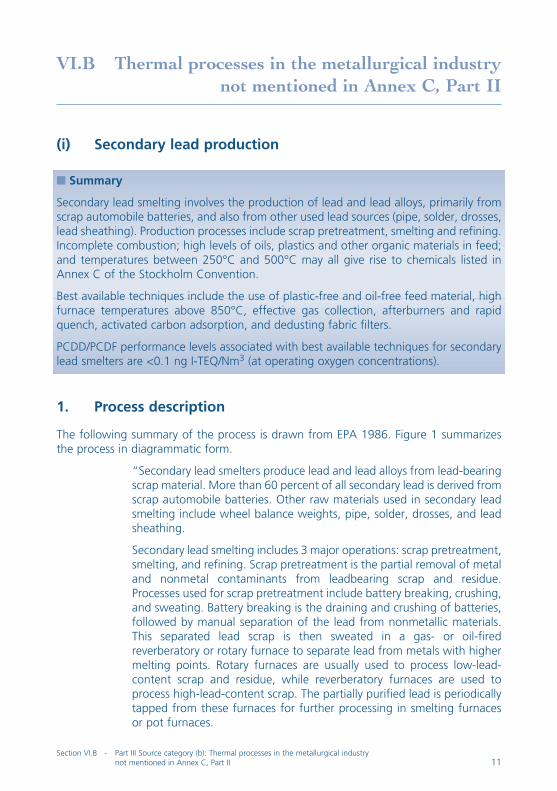


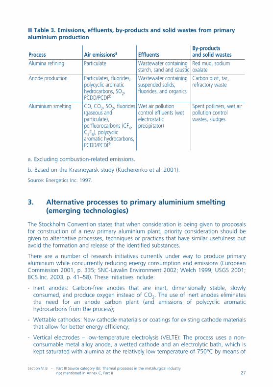


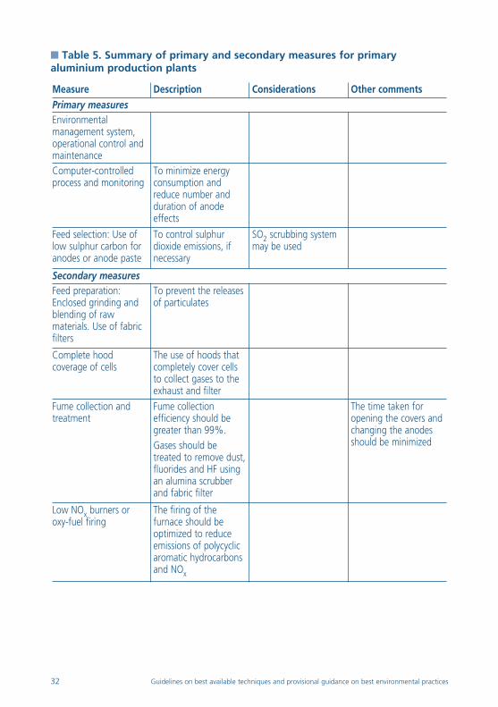


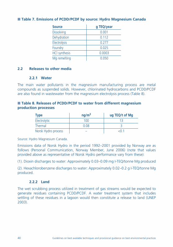


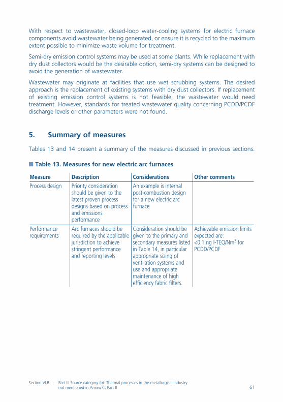

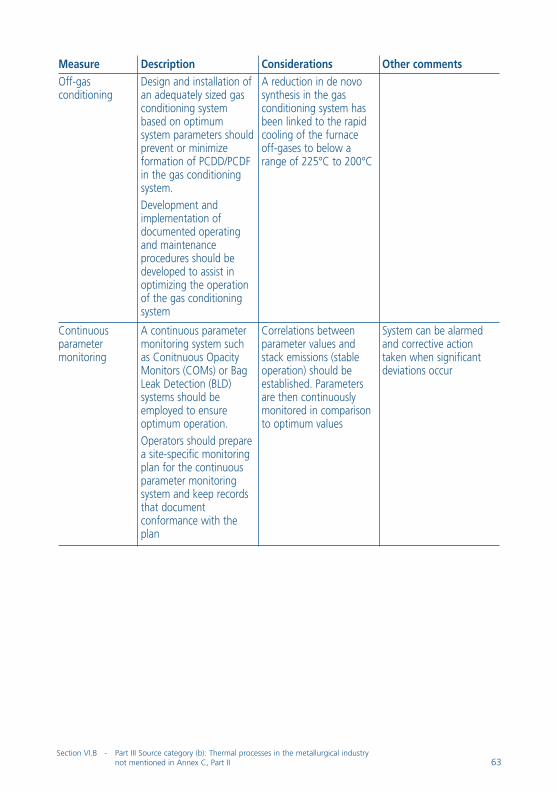

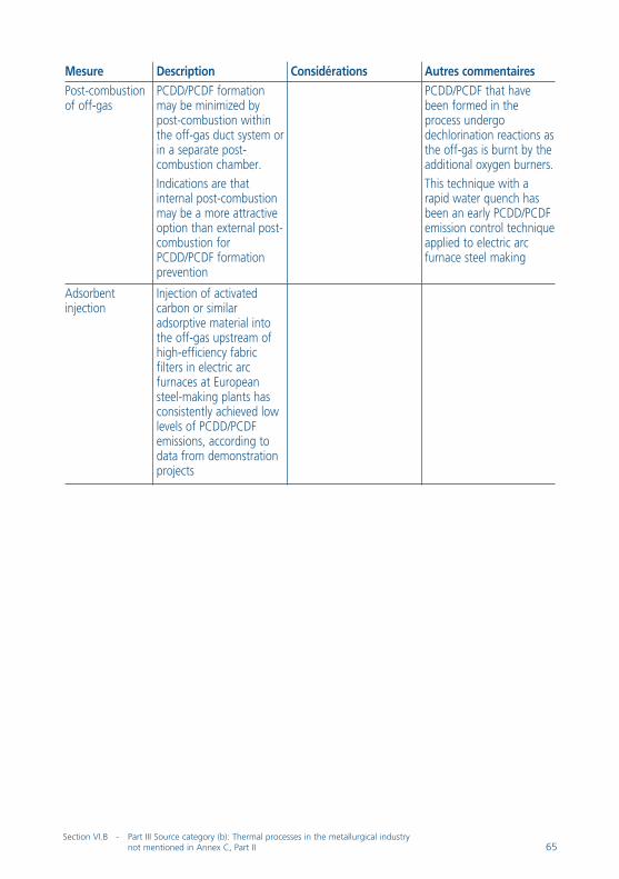
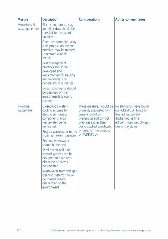


![Mechanical and Metallurgical Properties of Two-Layered ...Dr. Max Schoop ended up with an electrical arc spray [1]. Other major thermal spray processes include the detonation gun (D-Gun)](https://static.documents.pub/doc/80x56/60281d3141a1585f0c19d882/mechanical-and-metallurgical-properties-of-two-layered-dr-max-schoop-ended.jpg)


