NASA Technical Memorandum 104249 Thermal-Structural Test Facilities at NASA Dryden V. Michael DeAngelis and Karl F. Anderson NASA Dryden Flight Research Facility, Edwards, California 1992 NASA National Aeronautics and Space Administration Dryden Flight Research Facility Edwards, California 93523-0273 https://ntrs.nasa.gov/search.jsp?R=19920024958 2018-07-27T03:46:19+00:00Z
Transcript
NASA Technical Memorandum 104249
Thermal-Structural Test Facilities atNASA Dryden
V. Michael DeAngelis and Karl F. AndersonNASA Dryden Flight Research Facility, Edwards, California
1992
NASANational Aeronautics andSpace Administration
Dryden Flight Research FacilityEdwards, California 93523-0273
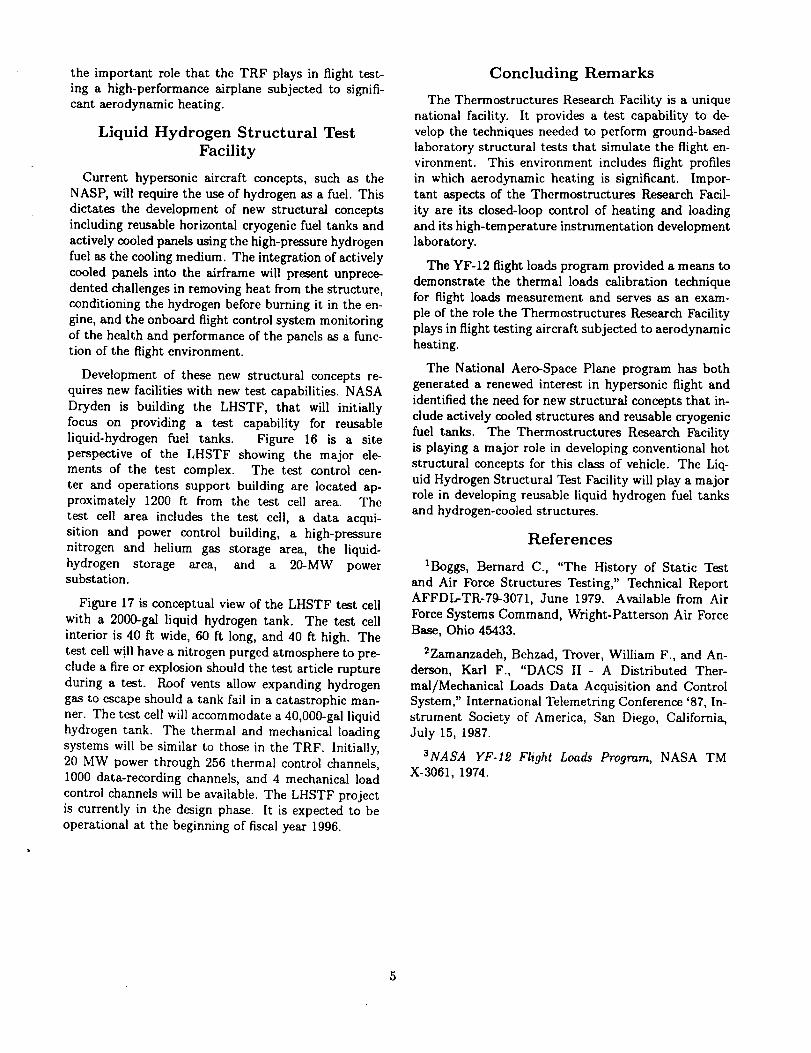
the entry ramp by a 136-ft-by-40-ftdoor. A 5-ton rail
crane servicesthe entiretest area floor.Systems for
mechanical, thermal, and vibrationtestingof struc-
tures, as well as for data acquisitionand test con-
trol,are incorporated in the facility.The data acqui-
sitionand testcontrolroom islocatedon the second
flooroverlookingthe main testarea. Instrumentation
and electronicsupport laboratoriesare alsoprovided.
Flame-plasma spray equipment islocatedin the stor-
age area; and the universalload frame machines are
housed in an area separate from the high-bay test area.
Mechanical Loading Systems
The TRF has three closed-loop electrohydraulic uni-
versal testing machines, each with a digital engineering
unit display and an X-Y recorder. The maximum load
capacities of the three machines are 10,000, 100,000,and 220,000 lb. The machines are used for static
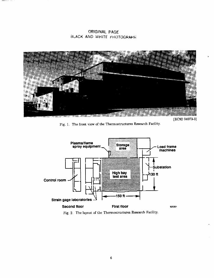
Ioadings of coupons and structural components atambient and elevated temperatures. Figure 3 is a pho-
tograph of the 220,000-1b machine applying a compres-Sion load to a 2-ft-by-2-ft titanium metal matrix com-
posite buckling-critical panel.
For mechanical loads tests on large structural com-
ponents and for applying loads to aircraft, the TRF
has a 40-channel electrohydraulic closed-loop system.
Figure 4 shows a schematic diagram of the closed-loop
system. An inventory of hydraulic actuators, with ca-
pacities up to 60,000-1b tension and 80,000-1b compres-
sion, and load cells with up to 50,000-1b capacity, isavailable.
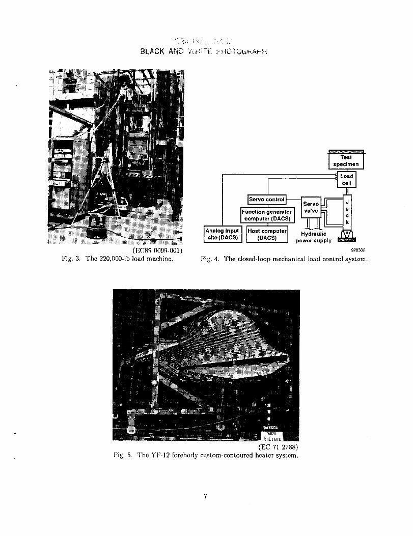
custom-contoured heater system. Quartz lamp heaterscan achieve heat fluxes up to 100 Btu/ft2-sec, temper-
ature rates up to 150 °F/sec, and maximum tempera-tures of 3000 °F. The TRF data acquisition and control
system (DACS) and the control of these custom heater
systems will be discussed in the next section.
Data Acquisition and Control System
The TRF DACS is a state-of-the-art system that has
an addressable, gain programmable, self-calibrating,1280-channel data acquisition capability. _ The system
has built-in redundancy and can handle three simul-taneous test activities while recording and displaying
real-time data. Data may be replayed after the test
and displayed in a variety of graphic and alphanumeric
formats. All test setup data entry and system checkout
functions are designed to be user-friendly.
The DACS primary function is to provide the meansto conduct real-time simulations of thermal and me-
chanical loads on full-scale aircraft and aircraft com-
ponents. The real-time system resources may be ded-
icated to a single test or may be shared among as
many as three independent test activities conductedsimultaneously. The system provides the capability
to acquire data from analog transducers such as ac-celerometers, flowmeters, heat flux meters, load cells,
potentiometers, pressure gages, resistance temperaturedevices, strain gages, and thermocouples.
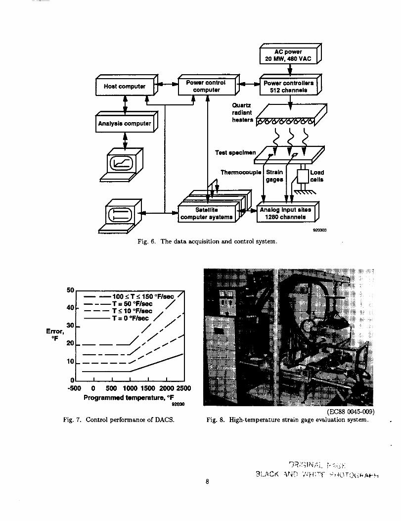
Figure 6 shows a schematic diagram of the DACS,
including an illustration of the closed-loop thermal con-
trol technique for heating a test specimen. The DACS
has a distributed processing architecture that uses five
classes of computers:
Heating Systems
Severalovens with programmable controlare avail-
able in the TRF for heatingcoupons and panels up to
2 ftby 2 ftin size.One oven has a temperature range
of -100 to 600 °F with liquidnitrogen as the cooling
medium. Two microprocessor-controlledovens, with
interiordimensions of approximately 2 ftby 2 ftby
2 ft,are also availablefor conducting apparent strain
teststo temperatures up to 2000 °F. One ofthese two
ovens has been modified so that itsatmosphere can be
purged using nitrogen or helium gas. A thirdtemper-
ature rate-controlledoven isused to testcoupons over
a temperature range of -320 to 600 °F. Six ovens are
the noncyclictype and are manually set to maintain
temperature. Maximum temperatures availablewith
these ovens range from 650 to 1300 °F.
Custom-contoured radiant heaters using quartz
lamps are used to heat the largerstructuralcompo-
nents.Figure 5 isa photograph ofthe YF-12 forebody
I.
.
.
4.
°
The host or centralcomputing facility,locatedin
the controlroom, for database management and
testoperation and monitoring.
Small mobile or "satellite" computers, located ei-
ther near the test specimen in the high-bay test
area or at a remote site, for small independent test
operation and for input-output control in a largertest.
An analysis computer, located in the control room,for test scenario definition, real-time data analy-
sis and display, and extended data reduction and
analysis functions.
A power control computer to perform thermal out-
put functions and to distribute the thermal powerloads.
A function generator computer to provide mechan-ical output functions (fig. 4).
TheDACShastwobasicoperatingmodes-- inde-pendenttestandcombinedtest. In the independenttestmode,atestisrunononeofthreesatellitecomput-ersthatarephysicallyconnectedto thehostcomputer.Thetestmaybecontrolledandmonitoredeitherfromthehigh-baytestareausingthesatellitecomputerorfromthe controlroomusingthehostcomputer.Inthis independenttestmode,channelcapacitiesinclude512data,100thermalcontrol,and12mechanicalcon-trol channels.
In thecombinedtestmode,thehostcomputerandonetothreesatellitecomputersareused.Thetestmaybemonitoredandcontrolledonlybythehostcomputerin thecontrolroom.In thismode,thechannelcapaci-tiesareafunctionof thenumberofsatellitecomputersusedandareshownin thetablebelow.
Channelcapacitiesforcombinedtest mode.
Thermal MechanicalNo. of Data control control
satellites channels channels channels
1 512 256 22
2 1024 512 40
3 1280 512 40
During a given test, all data channels are sampled
at the same rate. The sampling rate must be an in-
teger multiple of 4 samples/sec/channel, e.g., 4, 8, 12,16, 20, 24. Thus a satellite in the independent test
mode, with the capacity to acquire 5120 samples/sec,
is able to acquire 20 samples/sec from 256 channelsor 16 samples/sec from 320 channels. The maximum
single-channel sampling rate that the DACS will sup-port is 1280 samples/sec.
Temperature profiles for up to 512 thermal out-
puts are entered into the satellite computer systemsduring test scenario definition, before test initiation.
Adaptive control algorithms are used to determine
the output levels required to conform to the supplied
profiles within allowable error limits. A power dis-
tribution algorithm is used to minimize power peaks.During thermal control, the silicon-controlled rectifier
(SCR) power controller sends verification signals to the
thermal loads control subsystem (power control com-puter, satellite computer, and host computer) after
the SCR has received each thermal power output com-
mand. These verification indicators are available every
0.25 sec. They signify either a successful or unsuccess-
ful power output for that channel during the alternat-
ing current cycle. A successful output means that ei-
ther a requested firing occurred or no firing occurred
because none was requested.
The test operator interactively controls the applica-
tion of the thermal loads defined in the profiles. The
capability to start, hold, and stop thermal loading is
provided. For static temperature control (in which a
thermal control subsystem is in a hold status), the mea-sured temperatures axe within 4-0.5 percent or 4-5 °F,
whichever is greater, of the desired temperature over
the range from -300 to 2500 °F. For dynamic tem-perature control, the measured temperature error is
dependent on the temperature change rate, as shown
in figure 7.
The DACS includes seven interactive workstations
with high-resolution, color-graphic displays. Thermal
control deviation displays and a choice of custom data
displays are available to the user in windows. Three
color printers for hard copies of information displayed
in windows on the display workstations are provided.
Instrumentation Laboratory
An important aspect of all research programs is ob-
taining high-quality experimental data. The TRF in-
strumentation laboratory is vital to obtaining high-
quality structural test data.
The instrumentation laboratory has two principal
functions. The first is an applications function that
provides for the installation of a variety of instru-mentation on aircraft and structural test articles for
laboratory and flight testing. This includes state-of-
the-art bonded foil gages, weldable gages, and capac-
itive gages applied to materials such as aluminum, ti-
tanium, organic composites, and several of the nickel-based super alloys.
The second function is conducting R&D with focus
on the development of strain measurement techniques
at extreme temperatures (cryogenic to 2000 °F) on ad-
vanced state-of-the-art materials including metal ma-
trix composites and carbon-carbon composites. The
P_D instrumentation laboratory is equipped with a
high-temperature strain-gage evaluation system (fig-
ure 8) with both resistance heating and a Marshall fur-
nace to characterize strain gages on various materials
at temperatures up to 2000 °F. Characterizing strain
gages involves tests for apparent strain, gage factor def-
inition and stability, drift, lead wire attachment andlead wire resistance, strain transfer, etc. Plasma-flame
spray equipment is used to attach the high-temperature
strain sensors. Signal conditioning and data recording
systems, custom tailored for the instrumentation labo-
ratory, are used for test control and data recording and
analysis.
YF-12 Flight Research Program
Highlights
The largest, if not most complex, heating test con-ducted in the TRF was the Mach-3 thermal simulation
test of the YF-12 airplane. The comprehensive YF-
12 flight loads research program, conducted during
the late 1960's and early 1970's, was the first at-
tempt at applying a thermal loads calibration tech-nique to a flight vehicle. 3 Specific program objectivesincluded extending strain-gage load measurement to
high-performance aircraft, developing and demonstrat-
ing laboratory thermal simulation techniques, and eval-
programs. There were five distinct phases to the pro-
gram: instrumentation, static loads tests, flight test,laboratory heating tests, and flight data and analysis
correlation.
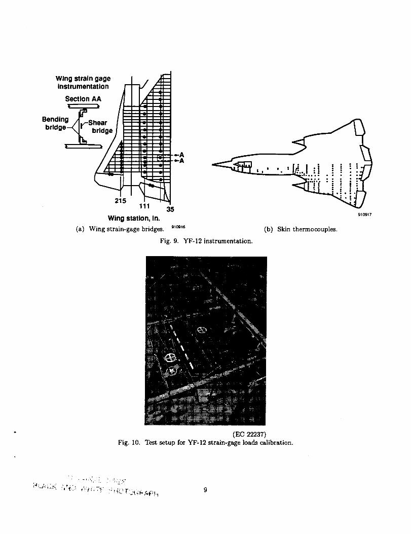
An objective of the instrumentation phase was to
design and develop a measurement system to providetemperature and loads measurement in both the flight
environment and laboratory ground tests. Figures 9(a)
and (b) illustrate the YF-12 instrumentation system.
Figure 9(a) shows some of the 101 strain gage bridgesthat were installed at three span locations in the left-
hand wing. Additional loads measurement locations
included three fuselage stations and all control surfaceactuators for measuring hinge moment. A satisfactory
method for bonding thermocouples to titanium with a
conductive adhesive was developed in the TRF instru-
mentation laboratory. For flight measurements, 561
thermocouples and 499 additional thermocouples for
laboratory heating tests were installed. Figure 9(b)shows the skin thermocouple locations for flight on the
upper surface of the left-hand wing.
Fifty-seven mechanically applied load conditions
were used to calibrate the strain gages installed on theairplane. Figure 10 is a photograph of the airplane in
the TRF being subjected to one of the loading condi-
tions. The airplane was supported on its landing gear
throughout the calibration. As calibration loads were
applied, the static load in the main gear was held nearly
constant by seven reactive loads applied through con-
toured pads resting on the centerline of the upper fuse-
lage at various bulkhead locations. Equations for the
measurement of shear, bending moment, and torquewere derived for each wing station by using single-pointloads.
Having instrumented the airplane and calibrated thestrain-gage instrumentation for loads measurement,
the flight test phase of the program was undertaken.
Symmetrical pitch maneuvers were performed at each
flight condition at eight different Mach numbers. Ateach Mach number, a maximum and minimum dy-
namic pressure was flown and a maximum and mini-
mum weight. Temperatures were measured at 449 skin
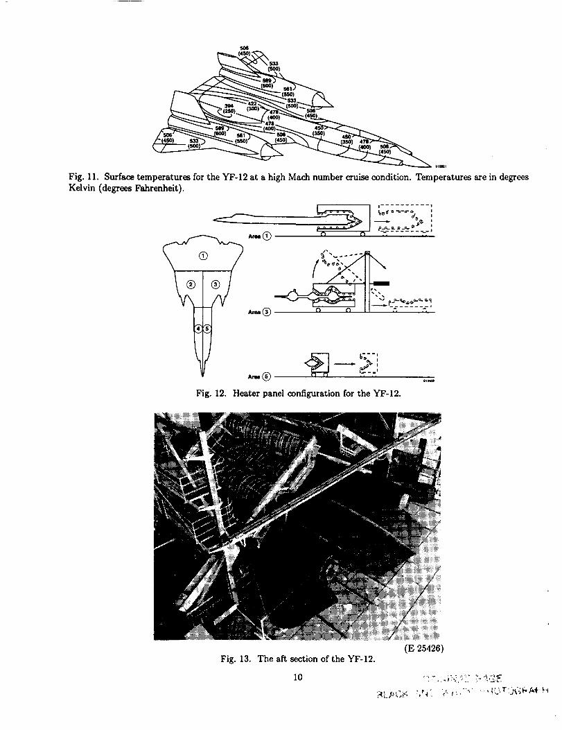
and 112 substructure locations. Figure 11 shows the
surface temperatures and isotherms at a high Mach
number cruise condition. From the figure it can be
seen that a complex ground heating system is needed
to simulate not only the heating rate but also the tem-
perature distribution over the surface of the airplane.
Flight data showed that the skin temperatures were atradiation equilibrium temperature during cruise and
that the wing spars adjacent to the engine nacelle werehotter than the skin. Since the spars were instrumented
with strain gages, it was imperative that the engine
heating effects be simulated during the ground heatingtests.
After the flight test phase, the airplane was prepared
for the laboratory heating tests. Figure 12 illustratesthe heater panel configuration used to encapsulate and
heat the 5000 ft 2 of surface area of the airplane. There
were two fore-body heaters, four center-body heaters,
and one large aft-body heater. In addition, a 42-in. di-
ameter cylindrical heater heated an area of 230 ft 2 onthe interior of the left-hand engine nacelle. Figure 13
is a photograph of the aft section of the YF-12 with
the aft heater removed and the "draw bridge" center-
body heaters raised. The tip of the engine nacelleheater can be seen. The ventral fins were removed and
were not part of the heating tests. More than 16,000
quartz lamps divided into 470 thermal control zones
were used to simulate Mach-2.5, -2.75, and -3.0 flight
profile heating tests. The lead wire for some of the 470
control thermocouples installed on the external skin of
the airplane is visible. Figure 14 is a photograph of the
YF-12 airplane enclosed in the quartz lamp heaters in
preparation for a heating test.
Figure 15 is a rear-view photograph of theYF-12 airplane during a Mach-3 thermal simulation
test. The bright glow at the left engine is caused by the
engine nacelle heater. Only the left-engine heat wassimulated because all of the strain-gage instrumenta-
tion was concentrated in the left wing, and none was
installed in the right wing. The maximum power used
during any of the tests was 3.5 MW. The YF-12 air-plane was heated to high Mach number aerodynamic
heating conditions more than 20 times with only mi-
nor problems. After the laboratory heating, the air-
plane was returned to flight status and made numer-
ous research flights without any problems related to
the heating tests.
The YF-12 Flight Loads Research Program made un-
precedented contributions in the area of hot-structures
technology. These include the first Mach-3 thermalsimulation of a complete aircraft that incorporated
major advances in digital heating control and real-
time data displays, a demonstration and validationof a thermal loads calibration technique, an appli-cation of structures instrumentation in an elevated-
temperature flight environment, an evaluation of state-
of-the-art analytical codes, and an extensive documen-
tation of the entire program in a NASA report. Fi-
nally, the YF-12 flight research program demonstrated
the importantrole that the TRF plays in flight test-
ing a high-performance airplane subjected to signifi-cant aerodynamic heating.
Liquid Hydrogen Structural Test
Facility
Current hypersonic aircraft concepts, such as the
NASP, will require the use of hydrogen as a fuel. Thisdictates the development of new structural concepts
including reusable horizontal cryogenic fuel tanks and
actively cooled panels using the high-pressure hydrogenfuel as the cooling medium. The integration of actively
cooled panels into the airframe will present unprece-
dented challenges in removing heat from the structure,
conditioning the hydrogen before burning it in the en-
gine, and the onboard flight control system monitoringof the health and performance of the panels as a func-
tion of the flight environment.
Development of these new structural concepts re-
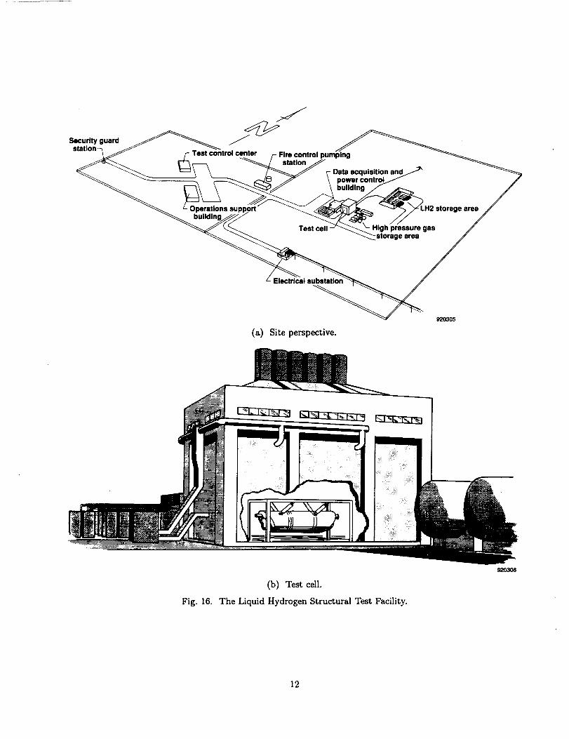
quires new facilities with new test capabilities. NASA
Dryden is building the LHSTF, that will initially
focus on providing a test capability for reusable
liquid-hydrogen fuel tanks. Figure 16 is a site
perspective of the LHSTF showing the major ele-ments of the test complex. The test control cen-
ter and operations support building are located ap-proximately 1200 ft from the test cell area. The
test cell area includes the test cell, a data acqui-
sition and power control building, a high-pressure
nitrogen and helium gas storage area, the liquid-hydrogen storage area, and a 20-MW powersubstation.
Figure 17 is conceptual view of the LHSTF test cell
with a 2000-gal liquid hydrogen tank. The test cell
interior is 40 ft wide, 60 ft long, and 40 ft high. Thetest cell will have a nitrogen purged atmosphere to pre-
clude a fire or explosion should the test article rupture
during a test. Roof vents allow expanding hydrogen
gas to escape should a tank fail in a catastrophic man-
ner. The test cell will accommodate a 40,000-gal liquid
hydrogen tank. The thermal and mechanical loading
systems will be similar to those in the TRF. Initially,20 MW power through 256 thermal control channels,
1000 data-recording channels, and 4 mechanical load
control channels will be available. The LHSTF project
is currently in the design phase. It is expected to be
operational at the beginning of fiscal year 1996.
Concluding Remarks
The Thermostructures Research Facility is a unique
national facility. It provides a test capability to de-velop the techniques needed to perform ground-based
laboratory structural tests that simulate the flight en-
vironment. This environment includes flight profiles
in which aerodynamic heating is significant. Impor-
tant aspects of the Thermostructures Research Facil-
ity are its closed-loop control of heating and loading
and its high-temperature instrumentation development
laboratory.
The YF-12 flight loads program provided a means to
demonstrate the thermal loads calibration techniquefor flight loads measurement and serves as an exam-
ple of the role the Thermostructures Research Facility
plays in flight testing aircraft subjected to aerodynamic
heating.
The National Aero-Space Plane program has both
generated a renewed interest in hypersonic flight and
identified the need for new structural concepts that in-
clude actively cooled structures and reusable cryogenic
fuel tanks. The Thermostructures Research Facility
is playing a major role in developing conventional hot
structural concepts for this class of vehicle. The Liq-
uid Hydrogen Structural Test Facility will play a majorrole in developing reusable liquid hydrogen fuel tanks
and hydrogen-cooled structures.
References
1Boggs, Bernard C., "The History of Static Test
and Air Force Structures Testing," Technical ReportAFFDL-TR-79-3071, June 1979. Available from Air
Force Systems Command, Wright-Patterson Air ForceBase, Ohio 45433.
_Zamanzadeh, Behzad, Trover, William F., and An-
derson, Karl F., "DACS II - A Distributed Ther-
mal/Mechanical Loads Data Acquisition and ControlSystem," International Telemetring Conference '87, In-
strument Society of America, San Diego, California,
July 15, 1987.
3NASA YF-12 Flight Loads Program, NASA TMX-3061, 1974.
5
ORIGINAL PAGE
BLACK AND WHITE- PHOTOGRAPH
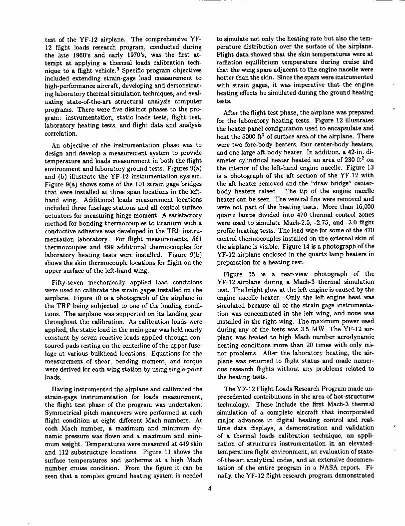
Fig. 1. The front view of the Thermostructures Research Facility.
I _'_Ii!_1ii__/.__ii___;_,,_!__l._._.':!._i_.::.::.it__ I i_Substatlont:..,.4_.!.i.Iiii_iii_.:iiii_iLi._._.ti....!._.l.:.ji_._.,,..,.,:, ,!2ili_:'_::ii4Hi h bay _:._i_i?_i!i:;._i_:.;._.:__ g _._:_:._:_._: 30 ft
_J _ _ test area _._i_._i IT'ntrol room - :_:._t_ .._.-.._._:__.,.&_l_Co ,'.:.:...._....... _: ._,..':_:_........._.._:_._:I--I
Strain gage laboratories --_ _
Second floor First floor _m_o_
Fig. 2. The layout of the Thermostructures Research Facility.
6
iii:!iiiiiiiiii!
Fig. 3.(EC89 0099-001)
The 220,000-1b load machine.
Teslspecimen I
II...,o.inpu,Ixo.,_mpu,erl[ site_oAcslJ .ydr_ul_
[ (DACS) ] power supply
920302
Fig. 4. The closed-loop mechanical load control system.
(EC 71 2788)
Fig. 5. The YI'-12 forebody custom-contoured heater system.
I AC power I20 MW, 480 VAC
I , . . t_l____f Power control k ..li r Power co_nlrollerl fl
rlost computer computer | 512 chlnnels I/l
I #IP-I #_ ou.,./ , -
c
,.,.! # .o.0i P'°"/_ J<'""
J(__IM ,telllie _ _i_A'nlilog Input fires flIcomputer.yetem,I 1 I=80o,,nn.., p
I 920303
Fig. 6. The data _quisition and control system.
50
40
30Error,
OF20_
10
0
-500
Fig. 7,
-- -- 100 < T < 150 °F/sec /
T = 50 °F/sec /
T__ 10 °F/sec i- 0 °F/sec / "'//.
_/./11-
I I I I I
0 500 1000 1500 2000 2500
Programmed temperature, °F92o3o
Control performance of DACS.
_--.,_ ['1
II_._CK :-_NO '/¢t-t;'r-f" m.>40,'rOt.;i-,_-.h
Wing strain gageInstrumentation
Se_lon AA
Bendingbrid
(a)
215111 35
Wing station, In.
Wing strain-gage bridges. 91o91s
Fig. 9. YF-12 instrumentation.
(b) Skin thermocouples.
910917
(EC 22237)Fig. 10. Test setup for YF-12 strain-gage loads calibration.
..... " r_,/_,'-'_-: ";_T"-'..
Fig. 11. Surface temperatures for the YF-12 at a high Maeh number cruise condition. Temperatures are in degrees
Kelvin (degrees Fahrenheit).
_¢._ I i .......... I..o_ Q. _ .m=. 9
Fig. 12. Heater panel configuration for the YF-12.
Fig. 13. The aft section of the YF-12.
10
(E 25426)
(E 25418)Fig.14. TheYF-12enclosedbyheatersin preparationforheatingtest.
Fig.15. TheYF-12Mach-3heatingtest.(ECN3708)
11
Jj__ou,r_ _
F" Test oonWol center r Fire control pump,ng
- _ _o_o5
(a) Site perspective.
Fig. 16.
(b) Test cell.
The Liquid Hydrogen StructuralTest Facility.
12
Form Approved
REPORT DOCUMENTATION PAGE OMBNoo7o4o Public reporling burdenfor this collectionof informationis estimaled to average 1 hourper response, includingthe time for reviewingtnstructions, searching existingdata souses,gatheringand maiM,tiningthe data needed, and completingand reviewing the collectionof information. Send comments regardingthis burden estimale or any other aspect o!thiscollectionof information,includingsuggestionsfor reducingthis burden, to WashingtonHeadquarter| Son/ices. Directoratofor InformationOperations lind Re[Dons,1215 Jeffersonearls Highway, Suite 1204. Arlington,VA 22202-4302, and to the Office of Management and Budget,Paperwork ReductionProject(0704.0188). Washington, DC 20503.
1, AGENCY USE ONLY (Leave blank) 2. REPORT DATE
August 19924. TITLE AND SUBTITLE
Thermal-Structural Test Facilities at NASA Dryden
6. AUTHOR(S)
V. Michael DeAngelis and Karl F. Anderson
7. PERFORMING ORGANIZATION NAMEtS) AND ADDRESStES)
NASA Dryden Flight Research FacilityP.O. Box 273
Edwards, California 93523-0273
g. SPONSORING/MONITORING AGENCY NAMEtS) AND ADDRESStES)
National Aeronautics and Space Administration
Washington, DC 20546-0001
3. REPORT TYPE AND DATES COVERED
Technical Memorandum
,5. FUNDING NUMBERS
WU-505-62-40
8. PERFORMING ORGANIZATIONREPORT NUMBER
H-1818
10, SPONSORING/MONITORINGAGENCY REPORT NUMBER
NASA TM-104249
11. SUPPLEMENTARY NOTES
Presentedat the Society for FlightTest Engineers23rd Annual Symposium, Hauppauge, New York, August 3-6, 1992.
12a. DISTRIBUTION/AVAILABILITY STATEMENT 12b. DISTRIBUTION CODE
Unclassified -- Unlimited
Subject Category 05
13. ABSTRACT (Maximum 200 words)
The National Aero-Space Plane (NASP) has renewed interest in hypersonic flight and hot-structures
technology development for both the airframe and engine. The NASA Dryden Thermostructures
Research Facility is a unique national facility that has been designed to conduct thermal-mechanical
tests on aircraft and aircraft components by simulating the flight thermal environment in the laboratory.
The layout of the facility is presented, which includes descriptions of the high-bay test area, the instru-
mentation laboratories, the mechanical loading systems, and the state-of-the-art closed-loop thermal
control system. The hot-structures test capability of the facility is emphasized by the Mach-3 thermal
simulation conducted on the YF-12 airplane. The Liquid-Hydrogen Structural Test Facility, which is
presently in the design phase, will provide the capability of thermally testing structures containing
hydrogen.
14. SUBJECT TERMS
Test facilities
Thermal-structural testing
17. SECURITY CLASSIFICATIONOF REPORT
Unclassified
NSN 7540-O1-280-5500
18. SECURITY CLASSIFICATIONOF THIS PAGE
Unclassified
19. SECURITY CLASSIFICATIONOF ABSTRACT
Unclassified
15. NUMBER OF PAGES
161(!. PRICE CODE
A0320. LIMITATION OF ABSTRACT
Unlimited
Standard Form 298 (Ray. 2-89)Prescribed by ANSI St¢l. Z39-1 !1