Thermal Technology Development Activities at the Goddard Space Flight Center - 2001 September 11, 2001 Dan Butler Thermal Engineering Branch/Code 545 NASA/GSFC http://watt-a-server.gsfc.nasa.gov/
Transcript
Thermal Technology DevelopmentActivities at the Goddard Space
• Variable Emittance Surfaces• Advanced Coatings• High Conductivity Materials• Electrohydrodynamic (EHD) Thermal Control Systems
Heat Pipes• Heat Pipes use capillary forces generated by a wick structure and the latent heat of
vaporization of a working fluid to transfer large amounts of heat at nearly constant temperature
• Heat is input to one end of the pipe where it vaporizes the working fluid• The vapor is transported to the condenser end of the pipe where it is condensed and
the heat is rejected• The condensed fluid travels back to the evaporator section in a capillary wick
structure, which can be grooves in the wall, screens, sintered metal, or other porous material
Vapor FlowCondensation
VaporizationLiquid Flow
Heat In Heat out
wick structure
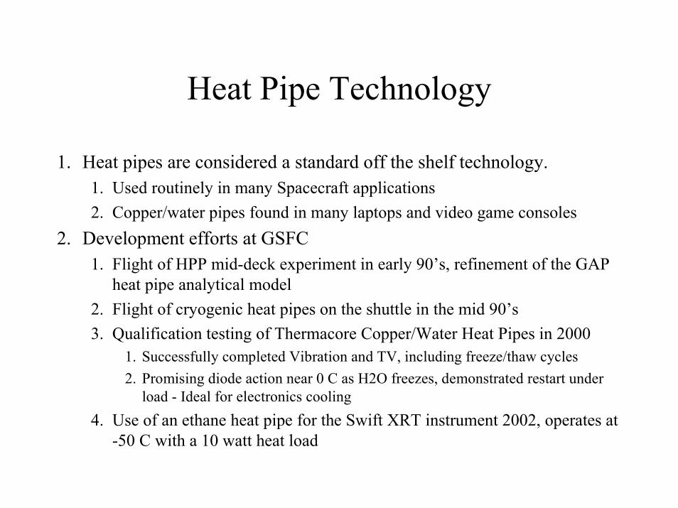
Heat Pipe Technology
1. Heat pipes are considered a standard off the shelf technology.1. Used routinely in many Spacecraft applications2. Copper/water pipes found in many laptops and video game consoles
2. Development efforts at GSFC1. Flight of HPP mid-deck experiment in early 90’s, refinement of the GAP
heat pipe analytical model2. Flight of cryogenic heat pipes on the shuttle in the mid 90’s3. Qualification testing of Thermacore Copper/Water Heat Pipes in 2000
1. Successfully completed Vibration and TV, including freeze/thaw cycles2. Promising diode action near 0 C as H2O freezes, demonstrated restart under
load - Ideal for electronics cooling4. Use of an ethane heat pipe for the Swift XRT instrument 2002, operates at
-50 C with a 10 watt heat load
Variable Conductance Heat PipesVCHP’s
• VCHP’s utilize a reservoir containing inert gas (nitrogen) to block part or all of the condenser, thus providing temperature control of the heat pipe to +/- 2 C
• Requires electrical controller and heater on the reservoir, linked to a feedback thermistor• VCHP’s are off the shelf technology, but not extensively used• GSFC applications on TPF flight experiment and Swift Loop Heat Pipe
Effective condenserEvaporator
Adiabatic section
Non-condensible gasVapor flow
Gas reservoir
Gas frontHeat input Heat output
Capillary Pumped Loops
• Capillary pumped loops (CPL’s) are two-phase heat transfer devices which use capillary forces for heat acquisition and fluid pumping with no moving parts
– Transfers high heat loads over long distances with vibration free operation and passive control– Factor of 30x improvement in wicking height over conventional heat pipes - greatly improves
ground testability and and eases spacecraft integration– Diode action offers shut down capability, minimize heater power requirements
Condenser
ReservoirVapor Transport Line
Heat In Wick Heat Out
EvaporatorSubcooler
Liquid Return Line
Capillary Pumped Loop TechnologyCPL
• CPL concept originated at the Lewis Research Center• Developed at GSFC starting in the early 80’s• Numerous test beds and shuttle flight experiments
– CPL GAS and Hitchhiker flight experiments in 1985 and 1986• Proof of Concept
– CAPL 1 and CAPL 2 flight experiments in 1994 and 1995• Point Design for the EOS-AM (now TERRA) Spacecraft• Single pump CPL verified for flight applications - “Starter Pump CPL”
– TPF Flight Experiment in 1997• Proof of Concept for multiple pump loop
– Multiple pump CPL’s • CAPL 3 flight experiment manifested on STS-108, Nov 2001• CCQ flight experiment (awaiting flight opportunity)
Starter Pump Capillary Pumped Loop
VAPOR LINE
FLOWR
ESERV
OIR
CONDENSERSTARTER PUMP
ISOTHERMALIZER HEAT PIPE
FLOW
RADIATOR
TEMPERATURE CONTROLLER
LIQUID RETURN LINE
COLD PLATE
CPL’s on TERRA (EOS-AM)• Terra launched December 18, 1999• Two-phase loops (CPLs) are on SWIR,
TIR and MOPPIT instruments• On the next day, the first CPL system in
a flight mission was started successfully.• All 3 CPLs continue to demonstrate
reliable, stable thermal control for their instruments
TERRA CPL Typical Layout
TERRA CPL - Coldplate• Coldplate provides the thermal sink for the instrument.• Contains the Capillary Starter Pump (Evaporator) that provides the capillary
pumping head via porous wick.
TERRA Normal OperationsThe Radiator, Liquid Lines and Reservoir Lines have orbital variations and vary depending on the instrument activities. The coldplate remains at a constant temperature during all activities.
Reservoir and Instrument Interface temperaturesremain constant
Radiator and Various Line Temperatures Vary depending on the heat load
Reservoir Setpoint Change
HST
HST SM 3B Servicing MissionSTS - 109 Jan 2002
– Near Infrared Camera and Multi Object Spectrometer (NICMOS) instrument installed on HST during Servicing Mission 2, Feb 1997
• Detectors cooled by nitrogen ice contained in a dewar• Thermal short in dewar detected shortly after SM2• Expected NICMOS lifetime of 4.5 years shortened to 1.7 years
– On SM 3B, the astronauts will install a brayton cycle, mechanical cryo-cooler to cool NICMOS detectors and resume operations
• Mechanical refrigerator must be capable of developing in excess of 7 watts of cooling power at 70 K
• Flexible Capillary Pump Loop built by Swales Aerospace selected to transfer energy from cryocooler to external radiator
– Precursor check-out mission (HOST) flown on STS-95 in October 1998 to verify cryocooler and CPL operation in micro-gravity -Highly Successful.
HST with CPL Radiators
ASCS (-V2) RADIATOR
ASCS CONDUIT
NCS CONDUIT
NCS (+V2) RADIATOR
HST with CPL Installed
WIRE HARNESS TO COSTAR/COS
CRYO VENTPORT
ELECTRONICSSUPPORT
MODULE (ESM)
ACSINTERFACE
PLATE
COSTAR/COS
ACS
COS CPL STOWAGE
ACSCPLS
COS CPL
HST Thermal Components AssemblyPRESSURE PLATE TOSTIS BULKHEAD INTERFACE(CHO-THERM NOT SHOWN)
DELRIN HEATPIPE SPACERS
CPL SADDLE (SADDLECOVER NOT SHOWN)
HOST Carrier Installed in the Payload Bay
CPL Temperature Control Law Response
0.0
2.0
4.0
6.0
8.0
10.0
12.0
14.0
16.0
18.0
20.016
:00
16:1
5
16:3
0
16:4
5
17:0
0
17:1
5
17:3
0
17:4
5
18:0
0
GMT Time
SUB
CO
OLI
NG
LIM
ITS
DEL
TA T
EMP
°C
Radiator Ctrl Evap Ctrl Delta HX1 Delta HX2 Res A
RES A
Radiator into Shadow
HPHX1 Exceeds Heat Load CapacityReservoir Boost Heater Turns on andRecovers CPL Control
Evap Ctrl
Delta HX1 andDelta HX2
Radiator Ctrl:Sun on Radiator
Multiple Evaporator Capillary Pumped Loop
VAPOR LINE
CONDENSERS
FLOW
RESER
VO
IR
CAPILLARY
PUMPS
FLOW
STARTER PUMP
RADIATOR
TEMPERATURE CONTROLLER
LIQUID RETURN LINE
CAPL 3 Flight ExperimentNRL/NASA Experiment
CAPL 3 Flight Experiment
• Follow on to CAPL 1 (STS-60, 2/94) and CAPL 2 (STS-69, 9/95) flight experiments
• Joint Naval Research Lab (NRL)/NASA partnership which will meet technology objectives for both the Department of Defense and NASA
• Two-phase ammonia thermal control system consisting of a capillary pumped loop with multiple capillary evaporators and parallel direct condensation radiators
• Includes a capillary starter pump and a back pressure regulator to assist with start-up in micro-gravity
• Will demonstrate heat load sharing between evaporators which provides heating from the loop as well as cooling
• Currently manifested on STS-108 in Nov 2001
dp
21
1
43
3
LiquidReturn Line
Condensers
Flow Regulators
Subcooler
Reservoir
TransducersBack Pressure Regulator
VCHP
CAPL 3 SchematicVapor Line
Flex Hose
Starter Pump
Vapor HeaderPressure
dp
2 4
Evaporators
Isolators
dp
Flex Hose
CAPL 3 Radiator Assembly (Upside Down)
Mounting Feet
Condensers
Subcooler Radiator
Evaporators
Reservoir
Electrical Interface Bracket
CAPL 3 Mission Description
• Mounted aboard GAS bridge structure inside the shuttle bay• 72 hour mission duration requested in SF1628• Nominal power: 800 W, max power approximately 1600 W• GSFC POCC for real-time Hitchhiker payload operation• Shuttle bay nadir facing (-ZLV), or colder orientation, for at least 54 hours
required, with 18 hours in bay to space attitude requested
50 W to each Evaporator 150 W /Evaporator 50 W /Evaporator
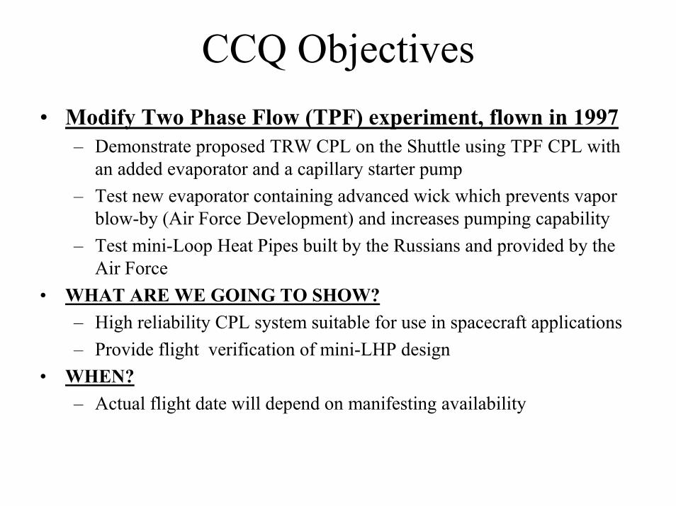
CCQ Objectives• Modify Two Phase Flow (TPF) experiment, flown in 1997
– Demonstrate proposed TRW CPL on the Shuttle using TPF CPL with an added evaporator and a capillary starter pump
– Test new evaporator containing advanced wick which prevents vapor blow-by (Air Force Development) and increases pumping capability
– Test mini-Loop Heat Pipes built by the Russians and provided by the Air Force
• WHAT ARE WE GOING TO SHOW?– High reliability CPL system suitable for use in spacecraft applications– Provide flight verification of mini-LHP design
• WHEN?– Actual flight date will depend on manifesting availability
TPF/CCQ Schematic
E2E1
E3E4
Liquid Collector
CPL
Con
dens
er 2
CPL
Con
dens
er 1
CPL
Res
ervo
ir
P
Starter Pump
Advanced Evaporator
Fill Valve
PCapillary VaporFlow Valve Vapor Line
VCHP 2 VCHP 1
Subc
oole
r
VaporCollector
Isolators
Vapor Distribution ManifoldLiquid Line
31
TPF Layout on Canister Lid
Variable Conductance Heat Pipe
Variable Conductance Heat Pipe
Differential Pressure Transducer
Isolators
Evaporators 3 and 4
Condenser
Capillary Vapor Flow Valve
Absolute Pressure Transducer
Cryogenic Capillary Pumped Loop (CCPL)
Condenser Spool
ColdReservoir
Evaporator
Liquid Cooled Shield
Liquid Return LineReservoir Line
Vapor Line
Cooling Source
Hot Reservoir
Capillary Pumped Loops (CPLs) are capable of transporting large amounts of heat over long distances and provide tight temperature control. They utilize capillary pumping forces (no moving parts).
• Several Cryogenic CPL’s have been developed and tested– Transport of 0.5 to 12 watts in 80 to 100 Kelvin range with Nitrogen– Transport of 0.25 to 3.5 watts in 35 to 40 Kelvin range with Neon– Temperature can be controlled to any desired level within the operating range
• CCPL can be used in a cryogenic thermal bus or as a temperature control device• CCPL flight experiment successfully flown on STS-95 in October 98
– Demonstrated start-up and transport up to 2.5 W@ 80 to 100 Kelvin– Included breadboard superconductor bolometer from Code 690– Future development - Operation in the 2 to 4 Kelvin range with Helium
CCPL Flight Unit DesignCCPL-5
Evaporator
LCSCold Reservoir
Line to Hot Reservoir
5th Generation CCPLTo Fly on STS-95 in Oct '98
Condenser
2.54 cm
CCPL-5 Weight: 191 gmsWorking Fluid: NitrogenTransport Length: 0.25 m
Loop Heat Pipes (LHP’s)• Description - LHP’s are basically similar to CPL’s - transfer large amounts of heat via
the heat of vaporization of the working fluid, and can be shut down• Invented in Russia in the 70’s• LHP’s compensation chamber (reservoir) is attached directly to the evaporator, versus a
remote location for CPL’s
Condenser/Subcooler
Vapo
r Lin
e
Liqu
id L
ine
QAl
Transition Active Zone
QINl
QSCl
QC
l
OPERATING TEMPERATURENO CONTROL OF COMPENSATION CHAMBER
0
5
10
15
20
25
30
35
0 50 100 150 200 250 300 350 400 450
Power Input (W)
Evap
orat
or T
empe
ratu
re (°
C)
OPERATING TEMPERATUREACTIVE CONTROL OF COMPENSATION CHAMBER
• Both Swales and Dynatherm LHP designs were flown in 1997 shuttleexperiments - Many Russian loops have also flown.
• Programs– GLAS Instrument (GSFC) - 2 LHP’s for laser and electronics – EOS/AURA, TES instrument (JPL) - 5 LHP’s for electronics, cryocooler– GOES/NEXT (Hughes) - 6 LHP’s for star tracker, electronics– VASMIR (JSC) - high flux LHP for rocket cooling– M1 Tank (US Army) - electronics cooling, testing up to 5 G’s– Nanosat & Mars Rover (JPL) - mini-LHP development
• Baselined for the MARS 03 Rover mission– Swift BAT Instrument (GSFC)- 2 loops cool detector plate– Boeing/Hughes 702 satellites use LHP’s with deployable radiators
• Several on-orbit and operating– Mini-LHP development program
GeoscienceLaserAltimeterSystem
10
GLAS LOOP HEAT PIPE
EOS-CHEM TES INSTURMENTLoop Heat Pipe Layout
MECHANICAL COOLER BLHP EVAPORATOR
MECHANICAL COOLER ALHP EVAPORATOR
IEM LHP EVAPORATOR
MECHANICAL COOLER ELECTRONICS LHP EVAPORATOR
SIGNAL CHAIN/ LASER HEAD ASSEMBLYLHP EVAPORATOR
SWIFT/BAT LHP
CompensationChamber 1
LHP 1 Evaporator
LHP 1 Condenser VaporLine 2
LiquidLine 2
LHP 2 Evaporator
CompensationChamber 2
LHP 2 Condenser
Liquid Line 1 Liquid Line 2
LiquidLine 1
Vapor Line 2
Vapor Line 1
Vapor Line 1
Mini-LHP• Miniaturization of existing
technology– currently have 1/2” dia evaporators– goal of 1/4” diameter evaporator– up to 10 of watt transport over < 1
meter length• Application to nanosats,
electronics cooling– allows isolation of spacecraft interior
during cold case– especially suitable for fleets of S/C
• Recent SBIR Phase 2 with TTH Research Inc./Thermacore
• HQ Award to GSFC (CETDP)
Mini-Loop Heat Pipe
Russian mLHP’s
Mini-LHP Technology Issues
• mLHP performance does not scale linearly– Thermal coupling (heat leak) between compensation chamber and
evaporator affects start-up capability and operating temperature – Previous experience on Capillary Pumped Loops shows that
performance affected by size
• Manufacturing capabilities on a small scale– Wick fabrication and secondary wick installation
• Development of a high conductance condenser• Thermal/Fluid dynamics on a small scale• Gravitational affects on liquid/vapor fluid management
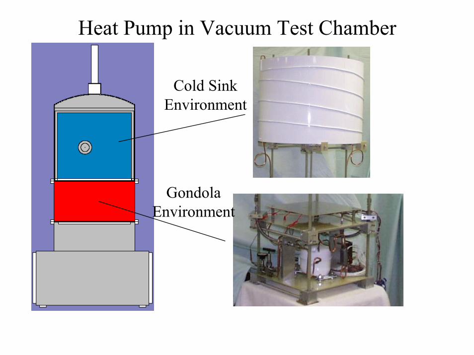
Heat Pumps
• Description - Heat pumps provide heat rejection at an elevated radiator temperature – Utilized in hot environments or to reduce radiator area (S/C real estate).
• Commercial units are unfit for vacuum and microgravity.• Program in FY 99/00 - collaboration with the University of Maryland
– Breadboard heat pump completed and tested in a vacuum environment• Upgrade of commercial unit for vacuum (approx 200 W)• Still need to address micro-gravity issues
– Mini-heat pump development study (10 to 20 W) in FY 00• Potential Applications - ULDB (balloon) thermal control in hot
environments, ISS, Lunar Base, Hi-power Comsats, Laser cooling • Penalty of weight and power
Heat Pump in Vacuum Test Chamber
GondolaEnvironment
Cold SinkEnvironment
Phase Change Thermal Storage
Variable Emittance Thermal Control Surfaces(VaryE)
• Variable emittance surfaces - Goal of 0.3 to 0.8 delta emissivity – Provides autonomous thermal control via a signal - “electronic louver”.
Three technologies in work - electrochromic, electrophoretic, and MEMS mini-louvers.
• Program - Baselined for thermal control demo on ST-5 mission (‘04)– ST-5 funding from TRL Level 5 to flight– Air Force SBIR for electro-chromic (Ashwin-Uhas)– GSFC SBIR for electrophoretic (Sensortex)– CETDP for MEMS louver (APL/Sandia)
• Application/Payoff - Generic applicability to all S/C and instruments, large and small. Potentially very inexpensive as a solid state device
MEMS Louvers
Thermal Coatings Technology on the EO-1 S/C Launched in November 2000
• Two Flight Thermal Coatings – White Paint– Z93P White Paint: Calorimeter (S/N 032) Current technology -
control sample– AZW/LA-II low alpha inorganic White Paint: Calorimeter
(S/N 033) New technology– Both coatings developed by AZ Technology
• Flown on calorimeters built at GSFC (reduce S/C thermal effects)
Calorimeters on EO-1
• The Calorimeters are mounted on a bracket and attached to the C-C radiator (Bay 4)
• The LA-II coating (“low alpha”) has a very low solar absorptance value when compared to other space application white paints.– A lower solar absorptance can provide improved radiator performance
when exposed to UV. This improvement can lead to smaller radiator sizes, saving spacecraft mass.
• LA-II optical properties verified maintaining stability with improved solarabsorptivity vs. Z93
• LA-II may provide cooler radiator temperatures when exposed to UV: – Data shows 5°C cooler in UV
• Baselined for the Swift Spacecraft (but it’s expensive)
• Incorporated K1100 composite panels as electrical box mounting panels/radiators on WIRE (1999)
• MAP - gamma alumina at low temperatures (2001)• Carbon-Carbon radiator on EO-1 (2000) • Diamond Material for electronics cooling• SBIR’s with Ktech for Annealed Pyrolitic Graphite (APG)
– Thermal Straps– Cryogenic Radiators for possible NGST application
Carbon-Carbon
• Carbon-Carbon (C-C) - Composite material that uses carbon for both the fiber and the matrix material– produced in a high temperature furnace in a lengthy process
• C-C has high thermal conductivity, good strength, and is lighter than Aluminum– C-C used in high temperature applications such as aircraft brakes,
Space Shuttle wing leading edge• Limited applications elsewhere to date, primarily due to cost and
production lead time• Carbon-Carbon Spacecraft Radiator Partnership (CSRP) formed to
promote the use of Carbon-Carbon as a radiator material– informal partnership with members from government and industry
C-C Radiator on EO-1
• The New Millenium Program’s EO-1 mission provided an opportunity for the CSRP to fly a C-C radiator– C-C radiator provided by CSRP at “no cost” to NMP
• The C-C radiator replaced one of 6 structural panels on the EO-1 Spacecraft - It is both a radiator and a structural member
• C-C Radiator consists of 1” Al honeycomb with 0.020” C-C face-sheets, approximately 28” by 28”– Utilizes 2 plies of P30X carbon fibers with carbon matrix established
by Chemical Vapor Infiltration– Epoxy coated for strength and contamination protection– Aluminum inserts bonded to honeycomb core for mounting of
electronics boxes and attachment to the S/C– Exterior coated with Silver Teflon for heat rejection– Flight qualification testing completed at GSFC
EO-1 C-C RADIATOR
CC Radiator Thermistor LayoutTRADCC6T
TRADCC3T
TRADCC2T
Removed to accommodate Calorimeter
TRADCC4T TRADCC5T
Flight Data
Thermal Model
C-C Radiator Lessons Learned
• C-C Radiator technology was successfully validated – C-C radiator panels can be used to reduce S/C weight– They can also be used as part of the S/C structure
• C-C has a niche, especially for high temperatures– Application on the Solar probe
• C-C still needs further development (my opinion)– Reduction in fabrication time and cost - high conductivity
“traditional” composites are competitive– CTE Interface issues with heat pipes
• Redundancy a good idea - we flew the spare panel• Possible follow-on missions: C-C foam for low CTE
mirrors/optical benches
CVD Diamond as a Heat Spreader• Diamond is a unique substance.
– Hardest known material – High thermal conductivity– Excellent mechanical strength – Electrical isolator, and may be used as a semiconductor.
• Recently received funding from HST to evaluate sample application as diode heat spreader
• Testing of Hi-K Diamond Underway (Norton Diamond)– TV testing for conductivity measurements completed -
conductivity approx. 1000 W/mK– Vibration test in sample application in work (HST relay cooling)
Encapsulated APG Material SystemCarbon Fiber Composite
k (W /m K)IN10176A-01 2504IN10176A-02 2134IN10176A-03 1998
Electrohydrodynamic Pumping (EHD)
• Description - EHD forces can be used to enhance heat transfer, provide fluid management, separate gas/liquid mixtures, and pump fluids.Utilizes electrical forces only, with no mechanical moving parts.
• Working fluids - Dielectric refrigerant such as freon 134a, hydrocarbon, or nitrogen (cryogenic)
• Program includes partnerships with the University of Maryland and Texas A & M– EHD flow management test bed– EHD single phase and two-phase thermal control loops– Cryogenic EHD pumping test (LN2)– MEMS level cooling
• Application - Heat exchangers, ISS environmental systems, thermal control systems, MEMS level micro-channel cooling of electronics
22-Oct-01 1997 IMECE 71
EHD PHENOMENA
• Electrohydrodynamics (EHD) is an interdisciplinary phenomena dealing with the interactions between electric fields and flow fields