121
SOLTRAIN Training Course for Experts & Professionals THERMAL USE OF SOLAR ENERGY
SOLTRAIN
Training Course for Experts & Professionals
THERMAL USE OF SOLAR ENERGY

SOLAR THERMAL SYSTEMS AND COMPONENTS
AEE - Institute for Sustainable Technologies
2
SOLAR THERMAL SYSTEMS AND COMPONENTS
AEE - Institute for Sustainable Technologies
3
SOUTHERN AFRICAN SOLAR THERMAL TRAINING AND DEMONSTRATION
INITIATIVE
Project Number 2608-00/2009
The project SOLTRAIN is financed by the Austrian Development Agency (ADA). Implementing organisation: AEE - Institute for Sustainable Technologies from Austria in cooperation with project partners from South Africa (Sustainable Energy Society of Southern Africa and Stellenbosch University), Namibia (Polytechnic of Namibia), Mozambique (Eduardo Mondlane University and N&M Logotech Lda.) and Zimbabwe (Domestic Solar Heating).
AEE - Institute for Sustainable Technologies
A-8200 Gleisdorf, Feldgasse 19, Austria Tel.: +43-3112-5886, Fax: +43-3112-5886-18
E-mail: [email protected]
© AEE INTEC AEE, Institute for Sustainable Technologies
A-8200 Gleisdorf, Feldgasse 19, Austria, 2009 Reprinting or reproduction, even partial or in modified form, is allowed by permission of AEE INTEC.

SOLAR THERMAL SYSTEMS AND COMPONENTS
AEE - Institute for Sustainable Technologies
4
SOLAR THERMAL SYSTEMS AND COMPONENTS
AEE - Institute for Sustainable Technologies
5
Contents
1 THE WORLD’S ENERGY SUPPLY ..................................................................... 8
2 SOLAR HEAT WORLDWIDE .............................................................................. 9
2.1 Main Markets ................................................................................................................................ 9
2.2 Market development 1999 to 2007............................................................................................. 13
2.3 Contribution of solar collectors to the supply of energy.............................................................. 14
3 SOLAR RADIATION .......................................................................................... 15
3.1 Global Radiation ......................................................................................................................... 15
3.2 Direct Radiation .......................................................................................................................... 18
3.3 Solar Radiation Data................................................................................................................... 18 3.3.1 Measuring Instruments........................................................................................................ 19
3.4 Solar Radiation on Tilted Surface............................................................................................... 21
3.5 Conversion of solar radiation energy into other energy forms ................................................... 22
4 SOLAR COLLECTORS ..................................................................................... 22
4.1 Plastic Absorber.......................................................................................................................... 24
4.2 Flat Plate Collector ..................................................................................................................... 24
4.3 CPC Collector ............................................................................................................................. 27
4.4 Evacuated Tube Collector .......................................................................................................... 28
4.4.1 Construction and working principle............................................................................................. 28
4.4.2 Direct flow evacuated tube collector........................................................................................... 30
4.4.3 Heat pipe evacuated tube collector ............................................................................................ 32
4.5 Concentrating Collectors ............................................................................................................ 33
4.5.1 Parabolic trough collector ........................................................................................................... 34
4.5.1.1 Working principle................................................................................................................. 35
5 PHYSICAL PROCESSES INSIDE A FLAT-PLATE COLLECTOR.................... 36
6 COLLECTOR MATERIALS ............................................................................... 38
6.1 Suitable absorber materials for flat-plate collectors ................................................................... 38
6.2 Absorber coating......................................................................................................................... 38

SOLAR THERMAL SYSTEMS AND COMPONENTS
AEE - Institute for Sustainable Technologies
6
6.3 Transparent cover materials....................................................................................................... 39
6.4 Insulating materials..................................................................................................................... 39
6.5 Casing......................................................................................................................................... 40
7 PERFORMANCE CRITERIA OF SOLAR COLLECTORS................................. 41
7.1 Characteristic Values of Flat-plate and Evacuated Tube Collectors .......................................... 41
7.2 Collector Efficiency Curve .......................................................................................................... 41
7.3 Area Definitions .......................................................................................................................... 43
7.4 Possible Improvements .............................................................................................................. 44
8 BUILDING INTEGRATION OF COLLECTORS ................................................. 45
8.1 Roof Integration of Solar Collectors............................................................................................ 45
8.2 Collector Assembly with Frame Structures ................................................................................ 46
8.3 Facade Integration of Solar Collectors ....................................................................................... 49
9 THERMAL ENERGY STORAGE ....................................................................... 50
9.1 Storage tank for natural circulation systems .............................................................................. 50
9.2 Pressurised Storage Tank .......................................................................................................... 51
9.3 Storage Tank Insulation.............................................................................................................. 54
9.4 Heat Losses................................................................................................................................ 54
10 OTHER COMPONENTS ................................................................................. 55
10.1 Expansion Vessel ....................................................................................................................... 55
10.2 Heat Exchanger .......................................................................................................................... 56 10.2.1 Coil heat exchangers........................................................................................................... 57 10.2.2 Plate heat exchanger (external) .......................................................................................... 59
10.3 Hot water-mixing valve ............................................................................................................... 60
10.4 Gravity break and safety valve ................................................................................................... 60
10.5 Air elimination ............................................................................................................................. 62
10.6 Pumps, safety valves, controller................................................................................................. 63
11 SYSTEM CONCEPTS AND APPLICATIONS................................................. 64
11.1 Swimming pool heating .............................................................................................................. 64
11.2 Thermosyphon systems for hot water preparation ..................................................................... 65 11.2.1 Direct system with open circulation..................................................................................... 65 11.2.2 Indirect systems with hydraulic separation.......................................................................... 67

SOLAR THERMAL SYSTEMS AND COMPONENTS
AEE - Institute for Sustainable Technologies
7
11.3 Domestic hot water systems with forced circulation................................................................... 68
11.4 Combisystems for hot water preparation and space heating ..................................................... 70
11.5 District heating ............................................................................................................................ 73
11.6 Industrial applications ................................................................................................................. 76 11.6.1 Industrial sectors involved and existing solar plants ........................................................... 76 11.6.2 Development of medium-temperature collectors ................................................................ 77 11.6.3 Integration of solar heat into industrial processes............................................................... 79 11.6.4 Pilot- and demonstration plants........................................................................................... 81
11.7 Solar cooling and air conditioning............................................................................................... 84 11.7.1 What is Solar Air Conditioning?........................................................................................... 84 11.7.2 How does solar air conditioning work?................................................................................ 85 11.7.3 Absorption refrigeration machines....................................................................................... 86 11.7.4 Adsorption refrigeration machines....................................................................................... 86 11.7.5 Sorption-assisted air conditioning ....................................................................................... 87 11.7.6 How well do solar-assisted air conditioning systems operate?........................................... 88 11.7.7 Energy balance.................................................................................................................... 88 11.7.8 Cost effectiveness ............................................................................................................... 89
12 DIMENSIONING OF DOMESTIC HOT WATER SYSTEMS ........................... 91
12.1 Hot water demand ...................................................................................................................... 91
12.2 The hot water storage tank capacity........................................................................................... 92
12.3 Collector area ............................................................................................................................. 92 12.3.1 Location, tilt, and orientation of the collectors ..................................................................... 93 12.3.2 Dimensioning guidelines ..................................................................................................... 95
13 DIMENSIONING - SOLAR COMBISYSTEMS ................................................ 95
14 LAY OUT OF SOLAR THERMAL SYSTEMS................................................100
14.1 Mode of operation..................................................................................................................... 100 14.1.1 High flow systems.............................................................................................................. 100 14.1.2 Low-flow systems .............................................................................................................. 101 14.1.3 Low-flow systems versus high-flow systems..................................................................... 102
14.2 Calculation of the membrane expansion vessel (MEV)............................................................ 108 14.2.1 Primary fluid in the vessel ................................................................................................. 108 14.2.2 Primary pressure in the MEV ............................................................................................ 109 14.2.3 Permeability....................................................................................................................... 109 14.2.4 Design of the solar membrane expansion vessel ............................................................. 109 14.2.5 Installation ......................................................................................................................... 113 14.2.6 Maintenance...................................................................................................................... 114
14.3 Calculation of heat exchangers ................................................................................................ 114 14.3.1 Introduction........................................................................................................................ 114 14.3.2 Plate heat exchanger ........................................................................................................ 116
SOLAR THERMAL SYSTEMS AND COMPONENTS
AEE - Institute for Sustainable Technologies
8
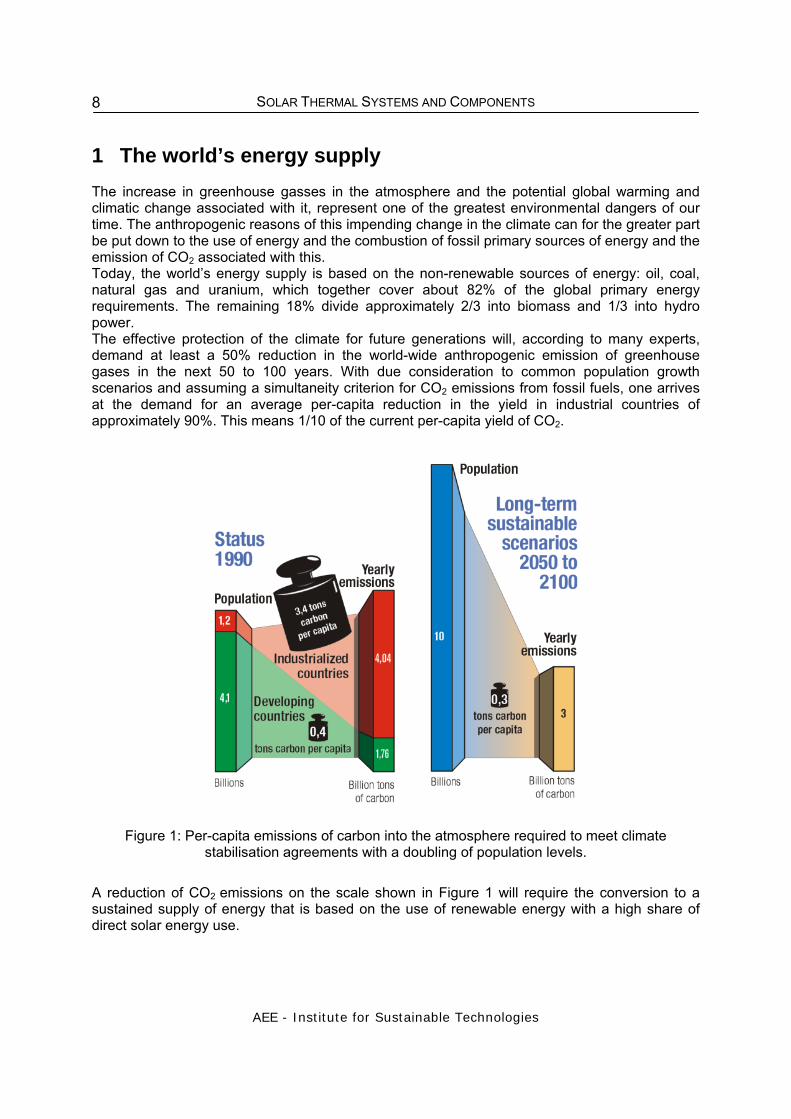
1 The world’s energy supply The increase in greenhouse gasses in the atmosphere and the potential global warming and climatic change associated with it, represent one of the greatest environmental dangers of our time. The anthropogenic reasons of this impending change in the climate can for the greater part be put down to the use of energy and the combustion of fossil primary sources of energy and the emission of CO2 associated with this. Today, the world’s energy supply is based on the non-renewable sources of energy: oil, coal, natural gas and uranium, which together cover about 82% of the global primary energy requirements. The remaining 18% divide approximately 2/3 into biomass and 1/3 into hydro power. The effective protection of the climate for future generations will, according to many experts, demand at least a 50% reduction in the world-wide anthropogenic emission of greenhouse gases in the next 50 to 100 years. With due consideration to common population growth scenarios and assuming a simultaneity criterion for CO2 emissions from fossil fuels, one arrives at the demand for an average per-capita reduction in the yield in industrial countries of approximately 90%. This means 1/10 of the current per-capita yield of CO2.
Figure 1: Per-capita emissions of carbon into the atmosphere required to meet climate stabilisation agreements with a doubling of population levels.
A reduction of CO2 emissions on the scale shown in Figure 1 will require the conversion to a sustained supply of energy that is based on the use of renewable energy with a high share of direct solar energy use.

SOLAR THERMAL SYSTEMS AND COMPONENTS
AEE - Institute for Sustainable Technologies
9
2 SOLAR HEAT WORLDWIDE 2.1 Main Markets Since the beginning of the 1990s, the solar thermal market has undergone a favorable development. At the end of 2007, a total of 209.2 million square meters1 of collector area, corresponding to an installed capacity 146.8 GWth were in operation in the 49 countries recorded in this report. These 49 countries represent 4 billion people which are about 60 % of the world’s population. The installed capacity in these countries represents approximately 85 – 90% of the solar thermal market worldwide. Compared with other forms of renewable energy, solar heating’s contribution meeting global energy demand is second only to wind power, and much bigger than photovoltaics’ contribution. This fact is often underestimated.
10 9.40.6 0.4
58
101.5 0.6
94
147
190
89
0
50
100
150
200
Solar ThermalHeat
Wind Power GeothermalPower
Photovoltaic Solar ThermalPower
Ocean TidalPower
Total Capacity in Operation [GW ], [GW ] and Produced el th Energy [TWh ], [TWh ], 2007el th
heat power
Total capacity in operation [GW] 2007
Produced Energy [TWh] 2007
Figure 2: Total capacity in operation [GW el], [GW th] 2006 and annually energy generated
[TWh el], [TWh th]. Sources: EPIA, GEWC, EWEA, EGEC, REN21 and IEA SHC 2008 According to the IEA report “Solar Heat Worldwide”2 at the end of 2007 the solar thermal collector capacity in operation worldwide equaled 146.8 GWth corresponding to 209.7 million square metres3. As shown in Table 1, 120.5 GWth were accounted for by flat-plate and evacuated tube collectors and 25.1 GWth for unglazed plastic collectors. Air collector capacity was installed to an extent of 1.2 GWth.
1 The IEA SHC Programme and the solar industry associations from Europe (ESTIF) the USA, Canada, and as well as the national associations from Austria Germany, the Netherlands and Sweden agreed to use a factor of 0.7 kWth/m2 to derive the nominal capacity from the area of installed collectors. 2 Weiss, W., Bergmann, I. Stelzer, R.: Solar Heat Worldwide, IEA Solar Heating and Cooling Programme, April 2009

SOLAR THERMAL SYSTEMS AND COMPONENTS
AEE - Institute for Sustainable Technologies
10
Table 1: Total capacity installed by the year 2007 [MWth]
Water Collectors Air Collectors Country
unglazed*** glazed evacuated tube unglazed*** glazed*** TOTAL [MWth]
Albania 34,95 0,17 35,12Australia 2.849 1.162,00 16,10 4.027,10Austria 426,22 2.064,69 30,09 2.521,00Barbados 57,96 57,96Belgium 34,18 93,63 8,66 136,46Brazil 68,21 2.511,25 0,25 2.579,70Bulgaria 19,32 19,32Canada 466,14 57,23 3,32 90,97 0,13 617,80China 7.280,00 72.618,00 79.898,00Cyprus 556,32 0,67 557,00Czech Republic 10,66 67,96 10,84 89,47Denmark 14,96 275,70 2,38 2,38 13,13 308,55Estonia 1,03 1,03Finland 0,35 10,91 0,91 12,17France * 73,15 991,55 23,10 1.087,80Germany 525,00 5.448,87 604,79 6.578,65Greece 2.496,34 4,76 2.501,10Hungary 1,96 28,94 1,79 32,69India 1.505,00 11,90 1.516,90Ireland 19,36 5,54 24,90Israel 16,94 3.455,83 3.472,77Italy 18,39 611,46 72,00 701,86Japan 4.777,20 88,95 304,06 8,76 5.178,96Jordan 588,23 5,04 593,27Latvia 3,75 3,75Lithuania 2,42 2,42Luxembourg 13,23 13,23Macedonia 13,35 0,14 13,49Malta 20,55 20,55Mexico 327,31 310,72 638,03Namibia 4,19 0,13 4,32Netherlands 240,47 230,65 471,12New Zealand 4,35 72,04 7,03 83,42Norway 1,12 7,85 0,11 0,84 9,92Poland 0,91 138,51 25,71 2,10 1,75 168,98Portugal 0,42 193,23 3,83 197,48Romania 48,72 48,72Slovak Republic 61,81 6,94 68,75Slovenia 81,07 0,81 81,88South Africa 440,03 173,38 613,40Spain 2,10 814,92 31,92 848,93Sweden 56,00 156,10 20,30 232,40Switzerland ** 148,68 303,44 17,79 586,60 1.056,52Taiwan 795,84 82,89 878,74Thailand 49,00 49,00Tunisia 151,57 1,03 152,60Turkey 7.105,00 7.105,00United Kingdom 194,54 18,90 213,44United States 19.347,55 1.329,19 404,86 0,07 160,82 21.242,49
TOTAL 25.074,11 46.390,78 74.119,76 986,18 197,33 146.768,15
*France: includes Overseas Departments **Unglazed air collectors in Switzerland: this is a very simple site-built system for hay drying purposes ***If no data is given: no reliable data base for this collector type available

SOLAR THERMAL SYSTEMS AND COMPONENTS
AEE - Institute for Sustainable Technologies
11
50%Evacuated tube
Unglazed Collector 17%
Air collector1%
Flat-plate32%
Figure 3: Distribution of the worldwide installed capacity by collector type
7,2
80
4,000
9,000
14,000
19,000
24,000
China UnitedStates
Turkey Germany Japan Australia Israel Brazil Austria Greece
Total Capacity [MW ]th
72
.61
8
evacuated tube
glazed
unglazed***
Figure 4: Total installed capacity of water collectors of the 10 leading countries at the end of
2007

SOLAR THERMAL SYSTEMS AND COMPONENTS
AEE - Institute for Sustainable Technologies
12
Cumulative installed capacity
Figure 5: Cumulative installed capacity of glazed flat plate and evacuated tube collectors in operation by economic region at the end of 2007
251
.922
4.4
197.
110
0.1
94.9
73.
36
0.1
56.8
51.
150
.542
.94
0.9
38.9
38.
02
8.3
19.
319
.118
.91
8.6
16.0
14.
814
.013
.112
.811
.61
1.0
9.8
7.7
6.6
5.8
5.7
4.3
3.6
3.5
3.1
2.9
2.5
2.3
2.2
2.1
1.8
1.7
1.6
1.3
0.8
0.8
0.7
0 0
50 50
100 100
150 150
200 200
250 250
300 300
Total capacity per 1.000 inhabitants [kW ]th
Cyp
rus
Isra
elA
ustr
iaG
reec
eB
arba
dos
Jord
anTu
rkey
Ger
man
yC
hina
Aus
tral
iaD
enm
ark
Mal
taSw
itze
rlan
d *
*Sl
oven
iaTa
iwan
Jap
anLu
xem
bour
gSw
eden
Spai
nN
ew Z
eala
ndPo
rtug
alFr
ance
*Tu
nisi
aN
eth
erla
nds
Bra
zil
Slov
ak R
epub
licIt
aly
Alb
ania
Bel
giu
mC
zech
Rep
ublic
Mac
edon
iaIr
elan
dU
nite
d S
tate
sPo
land
Sout
h A
fric
aU
nite
d Ki
ngdo
mH
unga
ryM
exi c
oB
ulga
ria
Rom
ania
Finl
and
Nam
ibia
Can
ada
Nor
way
Lati
vaIn
dia
Esto
nia
Tha
iland
Lith
uan
ia
Figure 6: Total capacity of glazed flat-plate and evacuated tube collectors in operation at the end
of 2007 in kWth per 1 000 inhabitants

SOLAR THERMAL SYSTEMS AND COMPONENTS
AEE - Institute for Sustainable Technologies
13
2.2 Market development 1999 to 2007 Analyzing the market development of hot water preparation and space heating, from 1999 to 2007, it can be seen that the market of flat-plate and evacuated tube collectors grew significantly during this time period. The main markets for flat-plate and evacuated tube collectors worldwide are in China and Europe as well as in Australia and New Zealand. The average annual growth rate between 1999 and 2007 was 23,6% in China and Taiwan, 20% in Europe and 16% in Australia and New Zealand. The market for flat-plate and evacuated tube collectors is slightly growing in Canada and the USA. The European market decreased in 2007 mainly due to the negative development Germany. After a peak in 1980s because of the second oil crisis, the market in Japan went down. The Japanese Ministry of Economy, Trade and Industry stopped the subsidies for solar thermal systems. This caused a break in of the marked, because without subsidies less stems were sold.
0
2,000
4,000
6,000
8,000
10,000
12,000
14,000
16,000
18,000
20,000
1999 2000 2001 2002 2003 2004 2005 2006 2007
Installed capacity [MWth/a]
China + Taiwan
Europe
Others
Australia + New Zealand
Japan
United States+Canada
Europe: EU 25 - Luxemburg + CH + Norway Others: Barbados, Brazil, India, Israel, Mexico, South Africa, Turkey
Figure 7: Annual installed capacity of flat plate and evacuated tube collectors from 1999 to 2007
0
2
4
6
8
10
12
1999 2000 2001 2002 2003 2004 2005 2006 2007
Installed capacity per 1,000 inhabitants [kWth/a]
China + Taiwan
Europe
Others
Australia + New Zealand
Japan
United States+Canada
Figure 8: Annual installed capacity of flat-plate and evacuated tube collectors in kWth per 1 000
inhabitants from 1999 to 2007

SOLAR THERMAL SYSTEMS AND COMPONENTS
AEE - Institute for Sustainable Technologies
14
In Figure 9 the distribution of solar thermal systems in different applications of the collector area, which was installed in 2007 is presented. The figure shows the distribution of the different applications in the different economic regions. In this figure only applications with glazed flat-plate and evacuated tube collectors have been taken into consideration. Unglazed collectors and air collectors are not included. The figure shows the dominance of systems that are installed to produce hot water for single-family houses. The share of solar combisystems (hot water preparation and space heating) for different applications is only relevant in Europe, China and Taiwan.
Australia + New Zealand
United States +Canada
Figure 9: Distribution of different solar thermal applications by economic region, which were
installed in the year 2007
2.3 Contribution of solar collectors to the supply of energy The annual collector yield of all solar thermal systems in operation by the end of 2007 in the 49 recorded countries is 88845 GWh (319841 TJ). This corresponds to an oil equivalent of 1209 million tons and an annual avoidance of 393 million tons of CO2.
SOLAR THERMAL SYSTEMS AND COMPONENTS
AEE - Institute for Sustainable Technologies
15
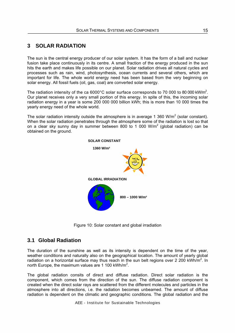
3 SOLAR RADIATION The sun is the central energy producer of our solar system. It has the form of a ball and nuclear fusion take place continuously in its centre. A small fraction of the energy produced in the sun hits the earth and makes life possible on our planet. Solar radiation drives all natural cycles and processes such as rain, wind, photosynthesis, ocean currents and several others, which are important for life. The whole world energy need has been based from the very beginning on solar energy. All fossil fuels (oil, gas, coal) are converted solar energy. The radiation intensity of the ca 6000°C solar surface corresponds to 70 000 to 80 000 kW/m2. Our planet receives only a very small portion of this energy. In spite of this, the incoming solar radiation energy in a year is some 200 000 000 billion kWh; this is more than 10 000 times the yearly energy need of the whole world. The solar radiation intensity outside the atmosphere is in average 1 360 W/m2 (solar constant). When the solar radiation penetrates through the atmosphere some of the radiation is lost so that on a clear sky sunny day in summer between 800 to 1 000 W/m2 (global radiation) can be obtained on the ground.
SOLAR CONSTANT
1360 W/m²
GLOBAL IRRADIATION
800 – 1000 W/m²
Figure 10: Solar constant and global irradiation
3.1 Global Radiation The duration of the sunshine as well as its intensity is dependent on the time of the year, weather conditions and naturally also on the geographical location. The amount of yearly global radiation on a horizontal surface may thus reach in the sun belt regions over 2 200 kWh/m2. In north Europe, the maximum values are 1 100 kWh/m2. The global radiation consits of direct and diffuse radiation. Direct solar radiation is the component, which comes from the direction of the sun. The diffuse radiation component is created when the direct solar rays are scattered from the different molecules and particles in the atmosphere into all directions, i.e. the radiation becomes unbeamed. The amount of diffuse radiation is dependent on the climatic and geographic conditions. The global radiation and the

SOLAR THERMAL SYSTEMS AND COMPONENTS
AEE - Institute for Sustainable Technologies
16
proportion of diffuse radiation are greatly influenced by clouds, the condition of the atmosphere (e.g. haze and dust layers over large cities) and the path length of the beams through the atmosphere.
Table 2. Global irradiance and diffuse fraction, depending on the cloud conditions
Clear, blue sky Scattered clouds Overcast sky
Solar irradiance [W/m²] 600 - 1000 200 – 400 50 - 150
Diffuse fraction [%] 10 - 20 20 – 80 80 - 100
The higher the amount of diffuse radiation is, the lower is the energy contents of the global solar radiation. The monthly and annual averages of daily radiation (kWh/m2, day) for selected locations are shown in Table 2.
Figure 11: Yearly average sums of global radiation on the earth.
Depending on the geographic location the yearly global radiation on a horizontal surface may vary between 1100 (Europe) and 2200 kWh/m2 (South America, Africa, Australia).
Table 3: Average monthly and yearly values of global solar radiation on a horizontal surface in
kWh/m².
Jan Feb Mar April May June July Aug Sep Oct Nov Dec Year Lat Vienna, Austria 25.2 43 81.4 118.9 149.8 160.7 164.9 139.7 100.6 59.8 26.3 19.9 1090 48.2 N Kampala, UG 174 164 170 153 151 142 141 151 155 163 154 164 1882 00.2 N Johannesburg 215 185 183 144 135 119 132 158 189 200 197 218 2076 26.1 S

SOLAR THERMAL SYSTEMS AND COMPONENTS
AEE - Institute for Sustainable Technologies
17
‐
50,00
100,00
150,00
200,00
250,00
Jan Feb Mar April May June July Aug Sep Oct Nov Dec
Vienna, Austria
Kampala, Uganda
Johannesburg
Figure 12: Average monthly values of global solar radiation on a horizontal surface
For the dimensioning of solar thermal systems, long-time average measured values, which are documented at meteorological stations, are important.
Figure 13: Annual global irradiation in Africa in kWh/m²( Source: Meteonorm)
kWh/m²
SOLAR THERMAL SYSTEMS AND COMPONENTS
AEE - Institute for Sustainable Technologies
18
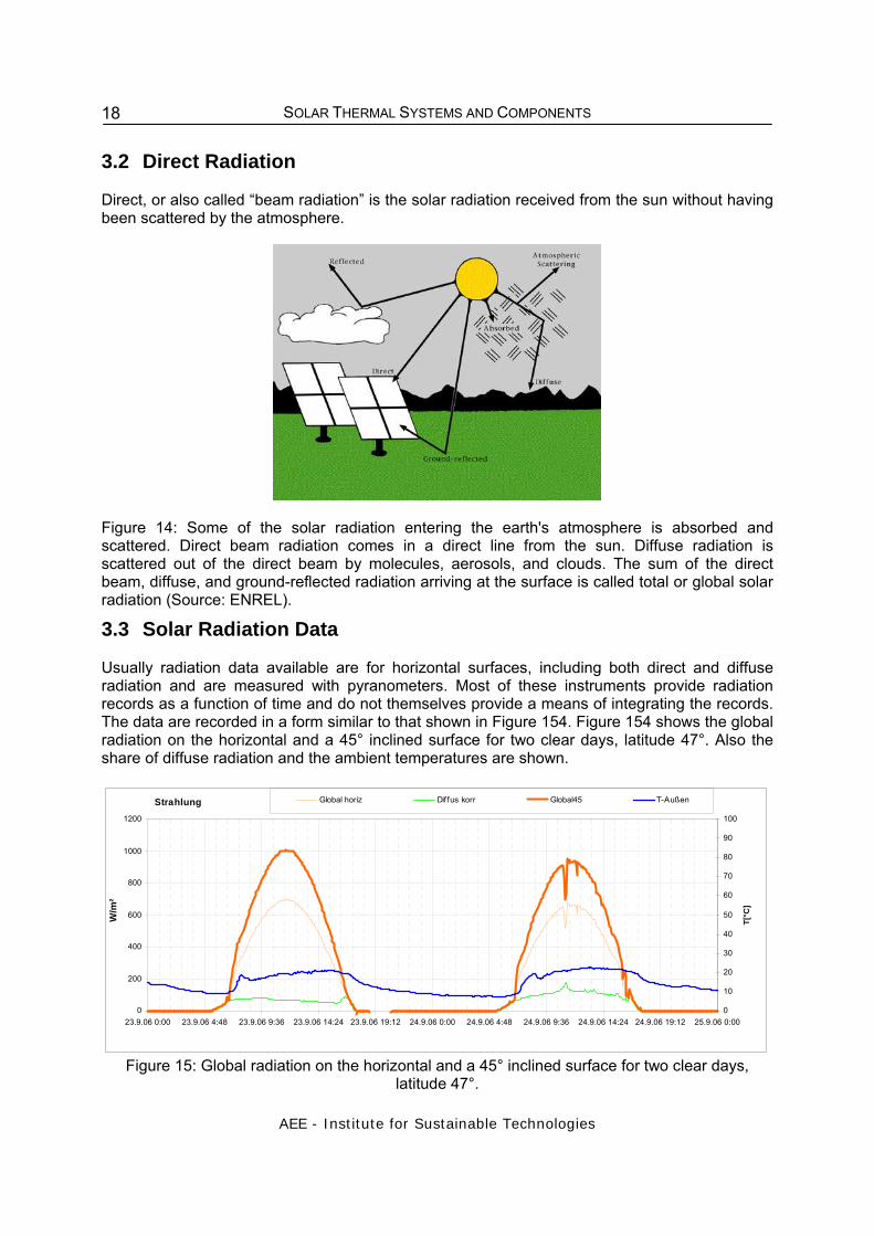
3.2 Direct Radiation Direct, or also called “beam radiation” is the solar radiation received from the sun without having been scattered by the atmosphere.
Figure 14: Some of the solar radiation entering the earth's atmosphere is absorbed and scattered. Direct beam radiation comes in a direct line from the sun. Diffuse radiation is scattered out of the direct beam by molecules, aerosols, and clouds. The sum of the direct beam, diffuse, and ground-reflected radiation arriving at the surface is called total or global solar radiation (Source: ENREL).
3.3 Solar Radiation Data Usually radiation data available are for horizontal surfaces, including both direct and diffuse radiation and are measured with pyranometers. Most of these instruments provide radiation records as a function of time and do not themselves provide a means of integrating the records. The data are recorded in a form similar to that shown in Figure 154. Figure 154 shows the global radiation on the horizontal and a 45° inclined surface for two clear days, latitude 47°. Also the share of diffuse radiation and the ambient temperatures are shown.
Strahlung
0
200
400
600
800
1000
1200
23.9.06 0:00 23.9.06 4:48 23.9.06 9:36 23.9.06 14:24 23.9.06 19:12 24.9.06 0:00 24.9.06 4:48 24.9.06 9:36 24.9.06 14:24 24.9.06 19:12 25.9.06 0:00
W/m
²
0
10
20
30
40
50
60
70
80
90
100
T[°C
]
Global horiz Dif fus korr Global45 T-Außen
Figure 15: Global radiation on the horizontal and a 45° inclined surface for two clear days,
latitude 47°.

SOLAR THERMAL SYSTEMS AND COMPONENTS
AEE - Institute for Sustainable Technologies
19
Solar radiation data are provided by meteorological stations and are usually also part of simulation programs. A global meteorological database for solar energy is provided by METEONORM, which is a global climatological database combined with a synthetic weather generator. The output are climatological means as well as time series of typical years for any point on earth. Further information see: http://www.meteotest.ch
http://www.retscreen.net 3.3.1 Measuring Instruments
Sunshine Recorder
An instrument widely used for the measurement of the duration of the sunshine is the Campbell- Stokes sunshine recorder (Figure 165). It consists of a solid glass sphere as a lens that produces an image of the sun on the opposite surface of the sphere. A strip of uninflammable paper is mounted around the appropriate part of the sphere, and the solar image burns a mark on the paper whenever the beam radiation is above a critical level. If the sun is covered by clouds, the line on the paper is interrupted. The lengths of the burned portions of the paper gives and index of the duration of bright sunshine.
Figure 16: Sunshine recorder (1)
Figure 17: Pyranometer (2), MacSolar (3)
Pyranometer Pyranometers are instruments for measuring global radiation (direct and diffuse). These are the instruments widely used all over the world. The detectors of these instruments must have a response independent of the wavelength of radiation over the solar energy spectrum. The detectors of most pyranometers are covered with one or two hemispherical glass covers to protect them from environmental impacts. The detectors convert the solar radiation into an electrical voltage, which is an indicator for the solar radiation. Other, more inexpensive instruments for measuring global radiation use a photovoltaic solar cell as receiver. They use the photovoltaic effect to determine the global radiation (e.g., MacSolar, Figure 16, right).

SOLAR THERMAL SYSTEMS AND COMPONENTS
AEE - Institute for Sustainable Technologies
20
Figure 18: Black and white pyranometer (4) Figure 19: Pyranometer with shading ring Black and white pyranometer The black and white pyranometer consist of star-shaped white and black thermal elements. The temperature differences between white and black surfaces result in thermal stress, which is the indicator for the solar radiation. Measurements of diffuse radiation can be made with pyranometers by shading the instrument from the direct (beam) radiation. This is done by means of a shading ring. The ring is used to allow continuous recording of the diffuse radiation without the necessity of continuous positioning of the shading device. Adjustments need to be made for changing declination only. This can be made every few days. Pyrheliometer A pyrheliometer is an instrument using a collimated detector for measuring solar radiation from the sun and a small proportion of the sky around the sun at normal incidence. It is used for measuring the beam radiation.
Figure 20: Pyrheliometer (5)

SOLAR THERMAL SYSTEMS AND COMPONENTS
AEE - Institute for Sustainable Technologies
21
3.4 Solar Radiation on Tilted Surface Usually just the global radiation on a horizontal surface is known, whereas solar collectors are usually tilted. In order to estimate the efficiency of a collector and the actual amount of solar energy collected, the solar radiation in the plane of the solar collector is required. In the following the Liu and Jordan’s isotropic diffuse algorithm (see Duffie and Beckman, 1991, section 2.19 and RETScreen /1/) is used to calculate the monthly average radiation in the plane of the collector, Hr.
The first term on the right-hand side of this equation represents solar radiation coming directly from the sun. It is the product of monthly average beam radiation Hb times a purely geometrical factor, Rb , which depends only on collector orientation, site latitude, and time of year4. The second term represents the contribution of monthly average diffuse radiation, Hd , which depends on the slope of the collector, β. The last term represents reflection of radiation on the ground in front of the collector, and depends on the slope of the collector and on ground reflectivity, ρg . This latter value is assumed to be equal to 0.2 when the monthly average temperature is above 0°C and 0.7 when it is below -5°C; and to vary linearly with temperature between these two thresholds. The monthly average daily beam radiation Hb is simply computed from:
Monthly average daily diffuse radiation is calculated from global radiation through the following formula:
• for values of the sunset hour angle ωs less than 81.4°:
• for values of the sunset hour angle ωs greater than 81.4°:
4 The derivation of Rb does not present any diffi culty but has been left out of this section to avoid tedious mathematical developments, particularly when the solar azimuth is not zero. For details see Duffi e and Beckman (1991) sections 2.19 and 2.20.

SOLAR THERMAL SYSTEMS AND COMPONENTS
AEE - Institute for Sustainable Technologies
22
3.5 Conversion of solar radiation energy into other energy forms Through the interaction of solar radiation and ground surface, a series of natural conversion processes will result. A major part of the heat that originates from the converted solar radiation is found again in the environment: air, ground, and surface waters are heated by solar radiation and these should thus be considered as renewable energy sources. Another part of the solar radiation is converted through biochemical processes into biomass (plants). This is also valid for fossil fuels, i.e. oil, coal, and natural gas, which have their origin in the same processes and are thus stored solar energy, but took place already million years ago. A relatively small part of the solar radiation energy is converted into wind, rain, and waves. From these phenomena stems the already since early times employed energy conversion methods such as the conversion of the energy of flowing water or wind energy into mechanical or electrical energy.
Figure 21: These technologies convert sunlight into usable forms of energy (Source: ENREL)
4 SOLAR COLLECTORS
The solar collector is the main part of a solar thermal system, that transforms solar radiant energy into heat that can be used for heating swimming pools, hot water preparation, space heating and even as heat for industrial processes. Basically it can be distinguished between three types of collectors
• uncovered (unglazed) collectors
• flat plate collectors
• evacuated tubular collectors
In addition to these three basic types there also exist special collector designs for medium to high temperature applications like parabolic trough collectors or fresnel collectors. In the following chapters the most used collector types are described.
SOLAR THERMAL SYSTEMS AND COMPONENTS
AEE - Institute for Sustainable Technologies
23
principle η0
[ ]
U
[W/m² K]
collector working temp.
appropriate application areas
simple absorber
0.90
20
15 – 30 °C
swimming pool
simple flat-plate collector
with glass cover (FP)
0.80
4
30 – 80 °C
hot water
FP with selective surface
(SS)
0.80
3
40 – 90 °C
hot water
space heating
FP with double anti-
reflective coated glazing and gas filling
0.80
2.5
50 – 100 °C
hot water
space heating cooling
evacuated tube collector
with SS (ETC)
0.65
2
90 – 130 °C
space heating
cooling process heat
ETC with compound
parabolic concentrator (CPC)
0.60
1
110 – 200 °C
space heating
cooling process heat
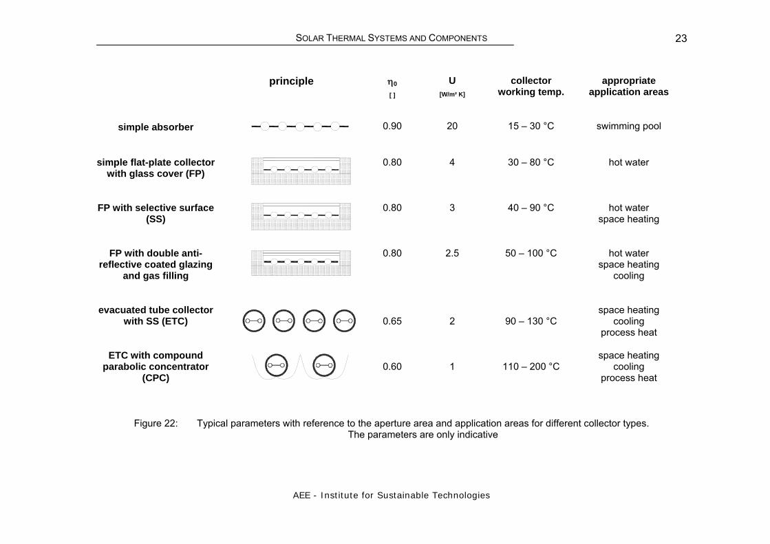
Figure 22: Typical parameters with reference to the aperture area and application areas for different collector types. The parameters are only indicative

SOLAR THERMAL SYSTEMS AND COMPONENTS
AEE - Institute for Sustainable Technologies
24
4.1 Plastic Absorber Due to their limited pressure and temperature durability, plastic absorbers are mainly used for pool water heating. In this case, the desired temperature level is only a few degrees higher than the ambient temperature. Thus, simple plastic absorbers, which due to their low operating temperature can be usually mounted uncovered on a flat roof, are sufficient. As they consist entirely of plastic, they have the advantage of single-circuit operation.
Figure 23: Different designs of uncovered, plastic collectors for swimming pool heating
4.2 Flat Plate Collector The most common collector used for hot water preparation and for space heating in Europe is the flat-plate collector. The flat-plate collector consists essentially of the collector box, the absorber, heat insulation and transparent cover.
Figure 24: Flat-plate collectors on a single family house and a multi-family house

SOLAR THERMAL SYSTEMS AND COMPONENTS
AEE - Institute for Sustainable Technologies
25
Flat-plate collectors use both beam and diffuse solar radiation, do not require tracking of the sun, are low-maintenance, inexpensive and mechanically simple. Solar radiation enters the collector through the transparent cover and reaches the absorber. Here the absorbed radiation is converted to thermal energy. A good thermal conductivity is needed to transfer the collected heat from the absorber sheet to the absorber pipes where the heat is finally transferred to the fluid. Usually a water/glycol mixture with anticorrosion additives is used as the heat carrying fluid. The fluid also protects the collector from frost damage.
Figure 25: Basic flat-plate collector for applications up to 80°C (Source: IEA Task 33)
The absorber plate is usually made of copper, aluminium or stainless steel, which is connected to flow tubes (risers) and the headers (manifold). The absorber plate is selective coated or in case of a simple collector just painted with a black paint.
absorber
transparentcover
framework structure
connection pipef
heat transfer medium pipe
insulation
Figure 26: Sectional views of a flat-plate collector. Source: Left picture (6)
1. Selective Coating
2. Absorber
3. Tube
4. Insulation
5. Rear panel
6. Manifold
7. Frame
8. Transparent cover
SOLAR THERMAL SYSTEMS AND COMPONENTS
AEE - Institute for Sustainable Technologies
26
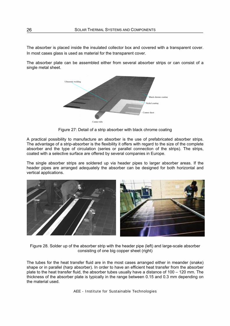
The absorber is placed inside the insulated collector box and covered with a transparent cover. In most cases glass is used as material for the transparent cover. The absorber plate can be assembled either from several absorber strips or can consist of a single metal sheet.
Copper sheet
Copper tube
Ultrasonic welding
Nickel coating
Black chrome coating
Figure 27: Detail of a strip absorber with black chrome coating
A practical possibility to manufacture an absorber is the use of prefabricated absorber strips. The advantage of a strip-absorber is the flexibility it offers with regard to the size of the complete absorber and the type of circulation (series or parallel connection of the strips). The strips, coated with a selective surface are offered by several companies in Europe. The single absorber strips are soldered up via header pipes to larger absorber areas. If the header pipes are arranged adequately the absorber can be designed for both horizontal and vertical applications.
Figure 28. Solder up of the absorber strip with the header pipe (left) and large-scale absorber consisting of one big copper sheet (right)
The tubes for the heat transfer fluid are in the most cases arranged either in meander (snake) shape or in parallel (harp absorber). In order to have an efficient heat transfer from the absorber plate to the heat transfer fluid, the absorber tubes usually have a distance of 100 – 120 mm. The thickness of the absorber plate is typically in the range between 0.15 and 0.3 mm depending on the material used.

SOLAR THERMAL SYSTEMS AND COMPONENTS
AEE - Institute for Sustainable Technologies
27
Figure 29: Absorber with meander tubes (left) and a harp absorber (right) (7)
4.3 CPC Collector Compound parabolic concentrators (CPC) combine the advantages of flat-plate collectors and parabolic trough collectors. By making use of both principles the CPC can function without continuous tracking and still achieve some concentration. The market share of this type of collector is rather limited. CPC collectors use a CPC (Compound Parabolic Concentrator) to concentrate solar radiation on an absorber. Because they are not focussing (non-imaging), they are a natural candidate to bridge the gap between the lower temperature solar application field of flat-plate collectors (T < 80°C) to the much higher temperature applications field of focussing concentrators (T > 200°C). Flat-plate collectors have an enormous advantage over other collector types because they collect radiation coming from all directions and therefore, they can be stationary on any given roof and all of the diffuse radiation is available to them. However, they also have the highest heat losses since they are proportional to the very large absorber area they possess. Because of these heat losses, the efficiency of flat-plate collectors at higher working temperatures of the solar loop is decreasing. Solar concentrators of the imaging focusing type have a small absorber area and therefore smaller heat losses. They provide high efficiency at high working temperatures. On the other hand, they have the disadvantage of having a smaller angle of view and therefore require a tracking system and can not collect most of the diffuse radiation. Collectors with CPCs can be designed so that they concentrate solar radiation by 1-2 factors and at the same time accept most of the diffuse radiation. Furthermore, these concentrators can be stationary or only need seasonal tilt adjustments.

SOLAR THERMAL SYSTEMS AND COMPONENTS
AEE - Institute for Sustainable Technologies
28
Figure 30: CPC collector (Source: Solarfocus)
4.4 Evacuated Tube Collector
4.4.1 Construction and working principle Because of technical reasons, most of the evacuated collectors are constructed as tube collectors. In this case, a thin absorber strip with selective coating is enclosed a highly light transparent and heat resistant glass tube. Through evacuation of the space between glass cover and absorber, the losses are reduced significantly as no convection and no heat losses by air conduction can occur.
Figure 31: Vacuum tube collectors
SOLAR THERMAL SYSTEMS AND COMPONENTS
AEE - Institute for Sustainable Technologies
29
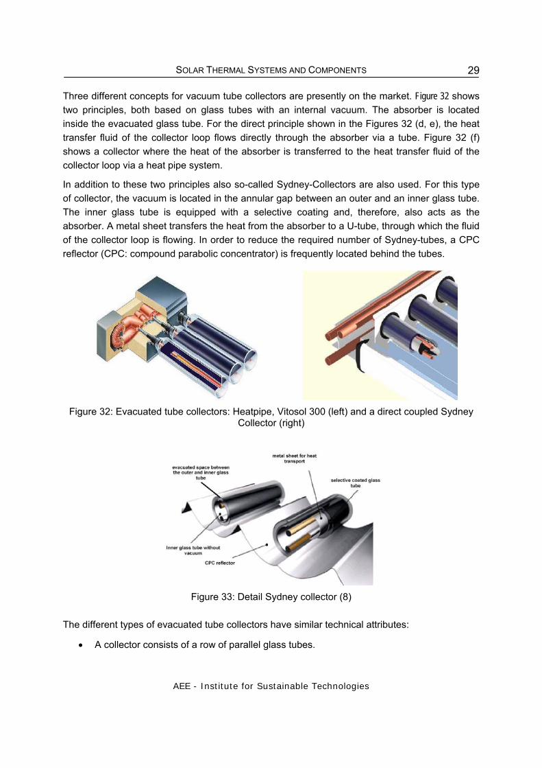
Three different concepts for vacuum tube collectors are presently on the market. Figure 32 shows two principles, both based on glass tubes with an internal vacuum. The absorber is located inside the evacuated glass tube. For the direct principle shown in the Figures 32 (d, e), the heat transfer fluid of the collector loop flows directly through the absorber via a tube. Figure 32 (f) shows a collector where the heat of the absorber is transferred to the heat transfer fluid of the collector loop via a heat pipe system.
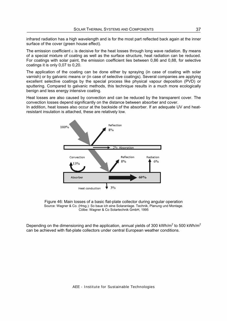
In addition to these two principles also so-called Sydney-Collectors are also used. For this type of collector, the vacuum is located in the annular gap between an outer and an inner glass tube. The inner glass tube is equipped with a selective coating and, therefore, also acts as the absorber. A metal sheet transfers the heat from the absorber to a U-tube, through which the fluid of the collector loop is flowing. In order to reduce the required number of Sydney-tubes, a CPC reflector (CPC: compound parabolic concentrator) is frequently located behind the tubes.
Figure 32: Evacuated tube collectors: Heatpipe, Vitosol 300 (left) and a direct coupled Sydney
Collector (right)
Figure 33: Detail Sydney collector (8)
The different types of evacuated tube collectors have similar technical attributes:
• A collector consists of a row of parallel glass tubes.

SOLAR THERMAL SYSTEMS AND COMPONENTS
AEE - Institute for Sustainable Technologies
30
• A vacuum (< 10-2 Pa) inside every single tube significantly reduces conduction losses and eliminates convection losses.
• The form of the glass is always a tube to withstand the stress of the vacuum. • The upper end of the tubes is connected to a header pipe.
The getter is another component evacuated tubes have in common. It is used in order to maintain the vacuum inside. During the manufacturing of most evacuated tubes the getter is inductively exposed to high temperatures. This causes the bottom of the evacuated tube to be coated with a pure layer of barium. This barium layer eliminates any CO, CO2, N2, O2, H2O and H2 out-gassed from the evacuated tube during storage and operation. The barium layer also provides a clear visual indicator of the vacuum status. The silver coloured barium layer will turn white if the vacuum is ever lost. This makes it easy to determine whether or not a tube is in good condition (see figure 34).
Vacuum faul tyVacuum presen t
Figure 34: Error–indication (http://www.solardirect.com/ and http://www.solar-water-
heater.com/product/trendsetter/basics.htm )
4.4.2 Direct flow evacuated tube collector If a single evacuated glass tube is used the whole interior is evacuated. For this configuration the flat or curved absorber as well as fluid inlet and fluid outlet pipes are inside of the vacuum. The absorber is coated with a selective surface. Single evacuated tubes often have diameters between 70 and 100 mm.
Figure 35: Sectional drawing of a direct flow pipe with flat absorber and u - tube Source: Frei, U.: Kollektoren in solarthermischen Systemen, SPF Solartechnik Prüfung
Forschung, TriSolar98

SOLAR THERMAL SYSTEMS AND COMPONENTS
AEE - Institute for Sustainable Technologies
31
The tubes are divided by configuration of the fluid pipes. The traditional type is a collector with separated tubes for fluid inlet and fluid outlet. Besides this type, also collectors with concentric inlet and outlet pipes are manufactured (see Figure 36. This means, that only the fluid outlet pipe is connected to the absorber. The pipe for fluid inlet is located inside the outlet pipe. The fluid flows back between the outer surface of the inner pipe and the inner surface of the outer pipe. The advantage of this construction is rotational symmetry. This offers the possibility to optionally orientate the absorber by rotating the whole tube. In this way any desired tilt angle can be achieved even if the collector is mounted horizontally. The efficiency of direct – flow single glass tubes is quite high but they require a good glass to metal seal that withstands the different heat expansion rates of those materials. A new type of concentric pipe configuration is the Lenz tube shown in Figure 36. The pipe for the fluid inlet is copper and the outlet pipe is glass. In addition to the rotational symmetry, no connection between glass and metal is needed to maintain the vacuum. The absorber is jammed to the outlet pipe. A graphite film between absorber and outlet pipe improves the heat transfer. Currently the most common type is the Sydney tube collector shown in Figure 32. It consists of two glass tubes fused together. The vacuum is located between the two tubes. The outside of the inner tube is usually coated with a sputtered cylindrical selective absorber (Al-N/Al). Inside of the inner pipe, the heat is removed by copper u-tubes, which are embedded in a cylindrical (aluminium) heat transfer fin.
Because the absorber is applied completely around the tube, often a (CPC-) reflector is placed under the tube to also use the radiation that passes between the parallel mounted tubes. This radiation is reflected to the absorber. There is no permanent connection between thermos flask tube and the heat conductor or the header of the collector. This means that tubes damaged due to exceptional reasons can easily be replaced.
A special type of the thermos flask is the Schott tube (see Figure 37). In this collector the heat transfer fluid flows directly through the absorbing inner glass tube. Radiation arriving between the absorber and outer tube can be used because of a mirror applied on the inner side of the outer pipe. Evacuated tubes consisting of two pipes fused together often have diameters between 40 and 70 mm.
Figure 36: Function and design of theLenz tube /Source: SWW 08/20006 S.46
Figure 37: Design of the Schott tube http://www.schott.com/solarthermal/images/rohrboden_400.jpg

SOLAR THERMAL SYSTEMS AND COMPONENTS
AEE - Institute for Sustainable Technologies
32
4.4.3 Heat pipe evacuated tube collector The main difference between a heat pipe tube and a direct flow tube is that the heat carrier fluid inside of the copper heat pipe is not connected to the solar loop. In this case there are two different ways of connection.
Figure 38: Principle of a heat pipe
The “wet” connection is shown in Figure 38. In the case of a “wet” connection, the fluid of the solar loop directly flows around the condenser of the heat pipes. In this case, no heat-conductive paste is needed but the exchange of tubes is more difficult. In the case of a “dry” connection the heat has to be transferred from the condenser through the material of the header tube. This way the installation and removal of the tubes is much easier than with direct flown pipes brazed to the header. On the other hand, heat-conductive paste often has to be used and thus requiring that the pipes be installed professionally. A heat pipe is hollow with low pressure inside. The objective is not to insulate, but rather to alter the state of the liquid inside. Inside the heat pipe is a small quantity of purified water and some special additives. When the heat pipe is heated above an adjustable temperature the water vaporizes. This vapour rapidly rises to the top of the heat pipe (condenser) transferring heat. As the heat is transferred to the condenser, the vapour condenses to form a liquid and returns to the bottom of the heat pipe to once again repeat the process. The condenser has a much larger diameter than the shaft to provide a large surface over which heat can be transferred to the header. To ensure circulation, a heat pipe collector has to be tilted at a minimum angle of operation (about 20°). The quality of the heat transport also can be seriously affected if the heat pipe contains too much condensable gasses. They can form a pocket of air in the top of the heat pipe. This has the effect of moving the heat pipe's hottest point downward away from the condenser.

SOLAR THERMAL SYSTEMS AND COMPONENTS
AEE - Institute for Sustainable Technologies
33
Frost protection is an issue for both types of collector. Outdoor temperatures lower than -10°C over a long period of time can cause freezing. To avoid this, a water/glycol mixture with anti-corrosion additives is used in the solar loop for frost protection. The heat pipe principle offers the theoretical possibility to avoid stagnation due to the restricted maximum temperature that the heat pipe can reach. Depending on the fluid and pressure used there is a temperature at which all the fluid within the heat pipe is vaporized and inside the condenser. In this case, the fluid is less effective in heat transportation. Because of that the temperature of the solar loop should be kept under the disruption temperature of the used glycol, which means working temperatures below 170°C. The reliable handling of this effect sensitively depends on the right amount of fluid and the right pressure inside of the heat pipe. Another approach to avoid stagnation is to use a memory metal to separate the fluid inside the heat pipe from the condenser if a certain temperature is reached. In direct flow vacuum collectors the stagnation temperature can reach 300°C so the glycol and the components of the solar loop have to be protected separately.
Figure 39: Thermosyphon system with evacuated tube collectors Source: http://greenterrafirma.com/evacuated_tube_collector.html
4.5 Concentrating Collectors In concentrating collectors, the sunlight is concentrated by parabolic troughs or concave mirrors on a pipe or a certain point; by this means high temperatures are reached (burning glass effect). These collectors are particularly used in solar thermal power plants and for process heat supply (250°C to 800°C).

SOLAR THERMAL SYSTEMS AND COMPONENTS
AEE - Institute for Sustainable Technologies
34
Figure 40: Concentrating solar cooker, south west of Ulan Bator, Mongolia
Figure 41: Parabolic trough collectors at a hotel in Turkey
(Source: SOLITEM, Germany)
In contrast to flat-plate collectors, which utilise global radiation (i.e. both direct and diffuse radiation), concentrating collectors have the disadvantage of only utilising the direct radiation. In addition, these collectors have to be tracked exactly according the corresponding position of the sun to ensure focussing of the solar radiation. A simple version of concentrating collectors are concentrating solar cookers.
4.5.1 Parabolic trough collector Parabolic trough collectors concentrate the sunlight before it strikes the absorber. Mirrored surfaces curved in a parabolic shape linearly extended into a trough shape focus sunlight on an absorber tube running the length of the trough. A heat transfer fluid is pumped through the absorber tube of the collector where the solar flux is transformed to heat.
Figure 42: Sketch of a parabolic trough collector (picture source: AEE INTEC)
Parabolic troughs are collectors designed to reach temperatures over 100ºC and up to 450ºC and still maintain high collector efficiency by having a large solar energy collecting area (aperture area) but a small surface where the heat is lost to the environment (absorber surface).

SOLAR THERMAL SYSTEMS AND COMPONENTS
AEE - Institute for Sustainable Technologies
35
Although different definitions are used, in this paper the concentration ratio refers to the ratio of the aperture area and the absorber surface (the surface that is hot and dissipates heat to the environment). The concentration ratio determines the temperature up to which the heat transfer fluid can be heated in the collector.
4.5.1.1 Working principle The reflecting surface of parabolic trough collectors, also called linear imaging concentrators, has a parabolic cross section. The curve of a parabola is such that light travelling parallel to the axis of a parabolic mirror will be reflected to a single focal point from any place along the curve. Because the sun is so far away, all direct solar beams (i.e., excluding diffuse) are essentially parallel so if the parabola is facing the sun, the sunlight is concentrated at the focal point. A parabolic trough extends the parabolic shape to three dimensions along a single direction, creating a focal line along which the absorber tube is run.
Figure 43: Parallel sun rays being concentrated onto the focal line of the collector (picture source: AEE INTEC)
Parabolic trough collectors—like other solar concentrating systems—have to track the sun. The troughs are normally designed to track the sun along one axis oriented in the north-south or east-west direction. As parabolic troughs use only direct radiation, cloudy skies become a more critical factor than when using flat-plate collectors, which can also use diffuse sunlight. Periodic cleaning of mirrors also is essential to assure an adequate parabolic trough field performance.
Figure 44: Tracking of the sun by a parabolic trough collector with the collector axis oriented north-south (picture source: AEE INTEC, Austria)

SOLAR THERMAL SYSTEMS AND COMPONENTS
AEE - Institute for Sustainable Technologies
36
5 PHYSICAL PROCESSES INSIDE A FLAT-PLATE COLLECTOR
In order to explain the physical processes taking place inside a collector the principle set-up of a flat plate collector and the relevant heat transfer mechanisms are shown in the following figure.
occurrenceof solar radiation
reflection on thepane of glass
heat loss through the pane of glass
heat loss through therear and side walls
reflection on absorber
Figure 45: Losses of a flat-plate collector
In the first instance, the solar radiation with a wave length of 0.3 < λ < 2.5 µm hits the transparent cover of the collector. Because of reflections both on the surface and at the interface (transmission) of the cover, a part of the radiation is lost to further utilisation in the collector. The reflection losses depend on the angle of incidence, the number of covers, and their refraction index, whereas the transmission losses are determined by the light transparency of the material. As plastic covers degrade relatively fast and thus show increasing transmission losses, glass covers have in particular proved to be successful.
Depending on the type of coating, the solar radiation, which is striking the absorber is converted almost entirely into heat. The coating should have both a high absorptance and the lowest possible emittance. The capability of absorption is characterised by the absorption coefficient α and mainly determined by the black colour of the absorber. The absorption coefficient for a solar coating with solar paint as well as for good selective coatings is between 0.94 and 0.97. A part of the heat being produced at the surface of the absorber is emitted again in form of infrared radiation. The infrared radiation and solar radiation differ in wavelength. The emitted
SOLAR THERMAL SYSTEMS AND COMPONENTS
AEE - Institute for Sustainable Technologies
37
infrared radiation has a high wavelength and is for the most part reflected back again at the inner surface of the cover (green house effect). The emission coefficient ε is decisive for the heat losses through long wave radiation. By means of a special mixture of coating as well as the surface structure, heat radiation can be reduced. For coatings with solar paint, the emission coefficient lies between 0,86 and 0,88, for selective coatings it is only 0,07 to 0,20. The application of the coating can be done either by spraying (in case of coating with solar varnish) or by galvanic means or (in case of selective coatings). Several companies are applying excellent selective coatings by the special process like physical vapour deposition (PVD) or sputtering. Compared to galvanic methods, this technique results in a much more ecologically benign and less energy intensive coating. Heat losses are also caused by convection and can be reduced by the transparent cover. The convection losses depend significantly on the distance between absorber and cover. In addition, heat losses also occur at the backside of the absorber. If an adequate UV and heat-resistant insulation is attached, these are relatively low.
Figure 46: Main losses of a basic flat-plate collector during angular operation Source: Wagner & Co. (Hrsg.): So baue ich eine Solaranlage. Technik, Planung und Montage.
Cölbe: Wagner & Co Solartechnik GmbH, 1995 Depending on the dimensioning and the application, annual yields of 300 kWh/m2 to 500 kWh/m2 can be achieved with flat-plate collectors under central European weather conditions.

SOLAR THERMAL SYSTEMS AND COMPONENTS
AEE - Institute for Sustainable Technologies
38
6 COLLECTOR MATERIALS The fundamental components of a flat-plate collector are the transparent cover, the absorber with its coating, the casing and insulation material.
6.1 Suitable absorber materials for flat-plate collectors Table 4: Thermal conductivity of different absorber materials
Absorber Material
Thermal Conductivity [W/mK]
Steel 50
Aluminium 210
Copper 380
6.2 Absorber coating The absorber coating has the task of absorbing as much of the incident sunlight as possible and converting it to heat. This applies regardless of the collector application! In the "thermal" range of the spectrum, i.e. in the infrared, it is important that as little energy be emitted as possible. Absorber coatings with high absorbtance α in the solar spectral range (0.3 - 2.5 µm) and simultaneously a low emittance ε in the wavelength range 2.5 - 50µm are termed "selective coatings". Absorber coatings are divided into the following classes: Selective coating: 0 ≤ ε < 0.2, α > 0.9 Partially selective coating: 0.2 ≤ ε < 0.5, α > 0.9 Non selective coating: 0.5 ≤ ε < 1.0, α > 0.9
Plain copper black paint galvanic coating physical vapour
deposition or sputtering
Figure 47: Absorption and emission of different absorber coatings

SOLAR THERMAL SYSTEMS AND COMPONENTS
AEE - Institute for Sustainable Technologies
39
For regions with high solar radiation like the Mediterranean countries or in the tropics non-selective coatings might be adequate. Selective absorber coatings are almost always used in flat-plate collectors in regions with low solar radiation like in middle or north of Europe.
6.3 Transparent cover materials
The transparent cover has the dual task of admitting the solar radiation to the collector and reducing the heat loss from the collector. The opacity of the cover in the spectral range of heat radiation leads to a "greenhouse effect" in the collector simultaneously protects the absorber against convective heat losses and wind. Glass and plastic materials are often used for the collector cover. The advantage of glazing is its proven long-term stability with regard to optical and mechanical properties. Table 5: Common cover materials for flat-plate collectors Cover Thickness
[mm] Weight [kg/m²]
Solar transmittance
Standard glass *) 4 10 0.84 Standard glass, tempered 4 10 0.84 Iron free glass, tempered 4 10 0.91 PMMA, ducted plate 16 5.0 0.77 PMMA, double ducted plate 16 5.6 0.72 Antireflective coated glass 4 10 0.95** *) Danger of breaking determined by high collector temperatures **additional costs low and worthwhile
6.4 Insulating materials Mineral wool and glass wool are often used as insulating material. Before a mineral wool product is incorporated, its outgassing must be investigated. Condensed outgassing products from the binder material of mineral wool can lead to precipitates on the transparent cover, if it is not counteracted. If polyurethane or polystyrol foam is used, it must always be protected against high temperatures by a covering layer. It has to be taken into consideration, that the stagnation temperatures of good selective coated collectors can reach temperatures as high as 200°C. Even simple collectors with black painted absorbers reach stagnation temperatures of about 140°C. The backside insulation of the collector has to resist these temperatures. Table 6: Possible insulating materials for flat-plate collectors Insulating material Max. allowable temperature
[ °C ]
Density
[kg/m³]
Conductivity
[W/mK] at 20°C
Mineral wool > 200 60 - 200 0.040
Glass wool > 200 30 - 100 0.040
Glass wool > 200 130 - 150 0.048
Polyurethane foam < 130 30 - 80 0.030
Polystyrol foam < 80 30 - 50 0.034
SOLAR THERMAL SYSTEMS AND COMPONENTS
AEE - Institute for Sustainable Technologies
40
6.5 Casing
For the casing basically aluminium, steel and polymeric materials are used. For roof integrated collectors wooden casings are also used.
The typical casing of a flat plate collector consists of a frame made of an extruded aluminium profile and a back plate out of either aluminium or weather proof steel. In order to reduce weight and costs back plates out of plastics become more and more common. Some manufactures even replace the aluminium profiles by plastic profiles.
Another possibility to build up the casing especially suitable for a large-scale automatic production line is the use of deep-drawn aluminium or plastic sheets.

SOLAR THERMAL SYSTEMS AND COMPONENTS
AEE - Institute for Sustainable Technologies
41
7 PERFORMANCE CRITERIA OF SOLAR COLLECTORS The solar collector is the main part of a solar thermal system because it transforms the solar radiation into heat. The collectors described in this chapter are designed for applications requiring energy delivery at temperatures up to 100 °C above ambient temperature. These collectors use both direct and diffuse radiation and do not require tracking the sun. The main applications are hot water preparation, space heating of residential, office and industrial buildings, air conditioning and industrial processes as well as seawater desalination. All collector constructions aim to convert the solar radiation into heat with high efficiency.
7.1 Characteristic Values of Flat-plate and Evacuated Tube Collectors Glazed or evacuated collectors are described by the following equation (Duffie and Beckman, 1991, eq. 6.17.2 /1/):
where Qcoll is the energy collected per unit collector area per unit time, FR is the collector’s heat removal factor, τ is the transmittance of the cover, α is the shortwave absorptivity of the absorber, G is the global incident solar radiation on the collector, UL is the overall heat loss coefficient of the collector, and Δ T is the temperature differential between the heat transfer fluid entering the collector and the ambient temperature outside the collector. Typical values for FR (τα) = 0.72 and FR UL = 4.90 (W/m²)/ºC for flat-plate collectors and FR (τα) = 0.58 and FR UL = 0.7 (W/m²)/ºC for an evacuated tube collector.
7.2 Collector Efficiency Curve The thermal efficiency of a collector is described by the efficiency curve. The efficiency of a collector is defined as the ratio of the energy amount transferred from the collector to the heat transfer medium to the incident radiant energy on the collector. The efficiency depends on the quality of the absorber surface, the geometry of the absorber, the heat conductivity of the absorber, the transparency of the cover, and the heat losses of the collector through infrared radiation, conduction, and convection. A quantitative comparison indicates that the efficiency is particularly dominated by the radiation losses.
SOLAR THERMAL SYSTEMS AND COMPONENTS
AEE - Institute for Sustainable Technologies
42
(tm* – ta**)/G [Km²/W] *temperature between inlet and outlet **ambient temperature
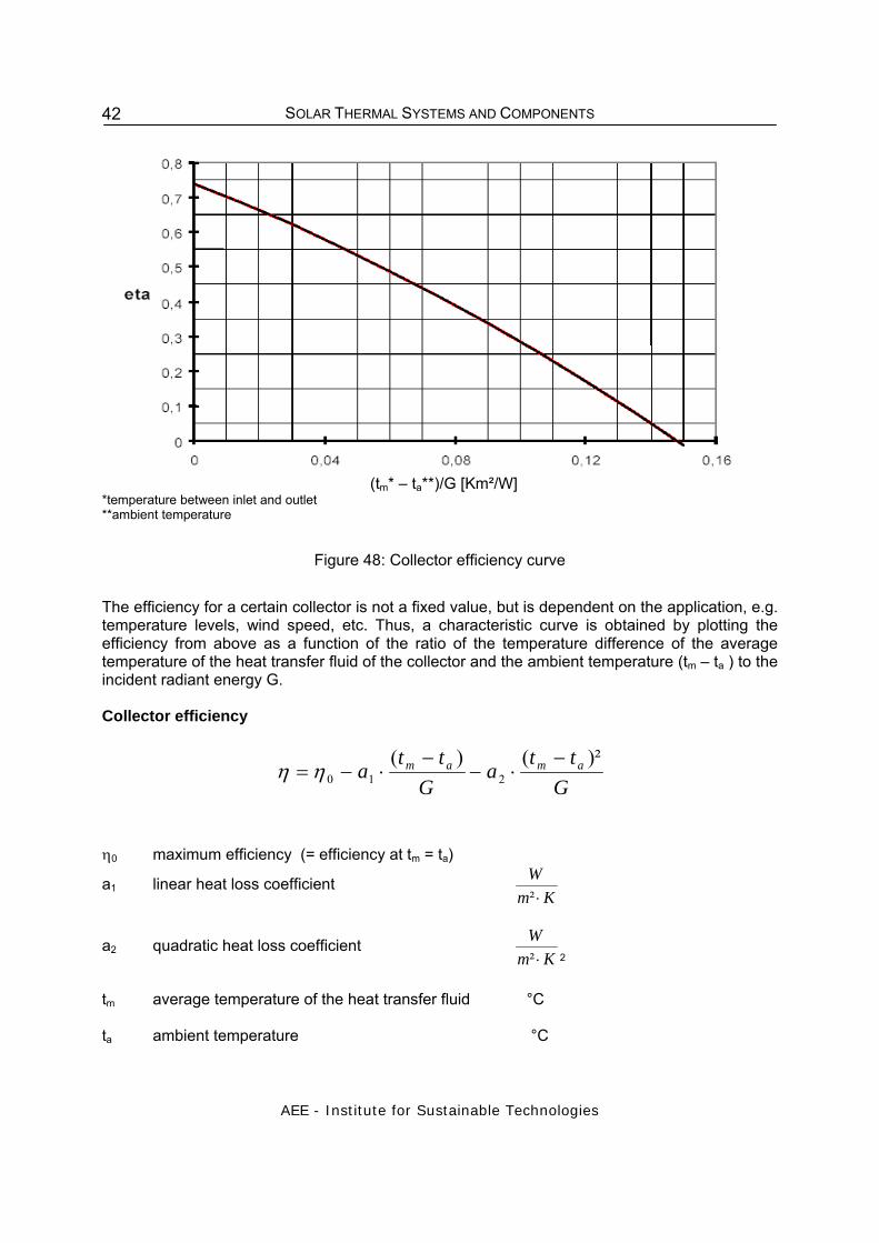
Figure 48: Collector efficiency curve
The efficiency for a certain collector is not a fixed value, but is dependent on the application, e.g. temperature levels, wind speed, etc. Thus, a characteristic curve is obtained by plotting the efficiency from above as a function of the ratio of the temperature difference of the average temperature of the heat transfer fluid of the collector and the ambient temperature (tm – ta ) to the incident radiant energy G. Collector efficiency
Gtt
aG
tta amam )²()(
210−
⋅−−
⋅−= ηη
η0 maximum efficiency (= efficiency at tm = ta)
a1 linear heat loss coefficient Km
W⋅²
a2 quadratic heat loss coefficient Km
W⋅² 2
tm average temperature of the heat transfer fluid °C ta ambient temperature °C

SOLAR THERMAL SYSTEMS AND COMPONENTS
AEE - Institute for Sustainable Technologies
43
G incident radiant energy (global radiation) ²m
W
The highest possible efficiency, i.e. the efficiency at which the average temperature of the collector tm and the ambient temperature ta are equal (no heat losses to the environment) is called the conversion factor η0. In this case only optical losses would occur. Stagnation temperature (°C) The stagnation temperature is the highest obtainable absorber temperature (no output withdrawn) when the solar radiation intensity is 1,000 W/m2 on the outermost transparent cover. Typical values are 140 – 150°C for simple black-coated flat-plate collectors, 180 – 210°C for selective coated flat-plate collectors and up to 260°C for good evacuated tube collectors.
(tm – ta)/G [Km²/W ]
Evacuated Tube Collector
Sim ple Flat-plate Collector
Uncovered Absorber
Selective Flat-plate Collector
Figure 49: Typical efficiency curves for different collector types
7.3 Area Definitions

SOLAR THERMAL SYSTEMS AND COMPONENTS
AEE - Institute for Sustainable Technologies
44
Figure 50: Definition of reference areas
7.4 Possible Improvements With standard flat-plate collectors operation temperatures up to 80°C can be reached. Because of its high heat losses, the basic flat-plate collector has to be improved to economically cover the lower medium temperature level up to 150°C. For applications in the temperature range of 80 to 120°C, in particular, there exist a number of possibilities to improve flat-plate collectors so that they can be suitable for those applications. In order to achieve this, it is necessary to reduce the collector heat losses mainly on the front side of the collector, but without sacrificing too much of the optical performance at the same time. Improvements include:
• hermetically seal collectors with inert gas fillings; • double covered flat-plate collectors; • vacuum flat-plate collectors; and • combinations of the above mentioned.
As an example, Figure 51 shows estimated efficiency curves of single, double and triple glazed flat-plate collectors when anti-reflection glazing ('AR-glass') is used.
0
0.1
0.2
0.3
0.4
0.5
0.6
0.7
0.8
0.9
0 0.05 0.1 0.15
(Tm-Ta)/G in Km²/W
effic
ienc
y (b
ased
on
aper
ture
are
a)
1 AR
2 AR
3 AR
standard flat-platecollector
operating temperature 80° to 120°C
Figure 51: Efficiency curves of a single, double and triple glazed AR collector in comparison
with a standard flat-plate collector with normal solar glass (Source: IEA SHC Task 33)

SOLAR THERMAL SYSTEMS AND COMPONENTS
AEE - Institute for Sustainable Technologies
45
8 BUILDING INTEGRATION OF COLLECTORS The most common way of integration for solar collectors into the building envelope is roof integration. In general all surfaces of a building that are oriented from southeast to southwest are suited for solar collectors. The solar yield may vary, depending on the tilt and orientation of the collector area as well as on the latitude, where the building is situated.
Figure 52: Building integration of solar collectors
8.1 Roof Integration of Solar Collectors Roof integration of solar collectors involves mounting the collector on top of the existing supporting structure, so that the collector also provides protection from rain, snow and wind. Assembly with the help of cranes is the standard method used for industrially manufactured large-scale collectors. In some projects, prefabrication have already been made to the extent that whole “solar roof” elements were prefabricated (consisting of supporting structures, heat insulation and collector).
Figure 53: (left) Crane assembly of large-area collectors (picture source: S.O.L.I.D.,
Austria).Figure 54: (right) Crane assembly of the entire roof elements with support construction and collector field (picture source: Wagner & Co, Germany).
SOLAR THERMAL SYSTEMS AND COMPONENTS
AEE - Institute for Sustainable Technologies
46
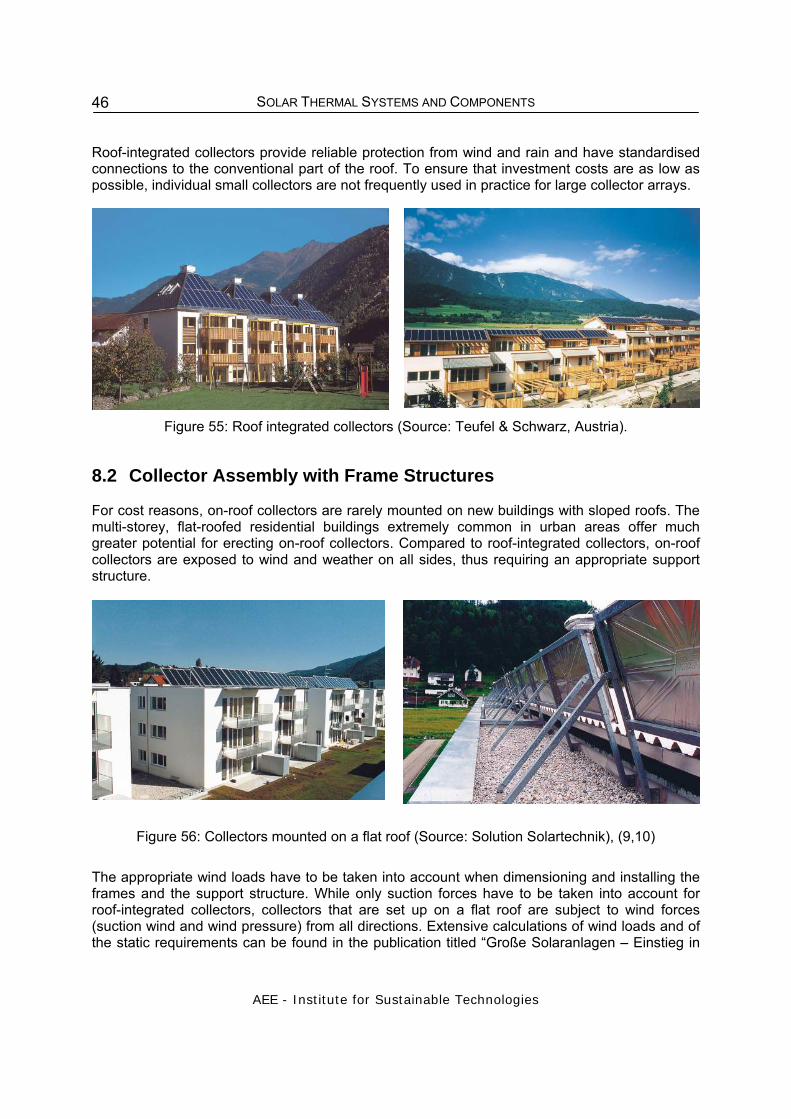
Roof-integrated collectors provide reliable protection from wind and rain and have standardised connections to the conventional part of the roof. To ensure that investment costs are as low as possible, individual small collectors are not frequently used in practice for large collector arrays.
Figure 55: Roof integrated collectors (Source: Teufel & Schwarz, Austria).
8.2 Collector Assembly with Frame Structures For cost reasons, on-roof collectors are rarely mounted on new buildings with sloped roofs. The multi-storey, flat-roofed residential buildings extremely common in urban areas offer much greater potential for erecting on-roof collectors. Compared to roof-integrated collectors, on-roof collectors are exposed to wind and weather on all sides, thus requiring an appropriate support structure.
Figure 56: Collectors mounted on a flat roof (Source: Solution Solartechnik), (9,10)
The appropriate wind loads have to be taken into account when dimensioning and installing the frames and the support structure. While only suction forces have to be taken into account for roof-integrated collectors, collectors that are set up on a flat roof are subject to wind forces (suction wind and wind pressure) from all directions. Extensive calculations of wind loads and of the static requirements can be found in the publication titled “Große Solaranlagen – Einstieg in

SOLAR THERMAL SYSTEMS AND COMPONENTS
AEE - Institute for Sustainable Technologies
47
Planung und Praxis” (Remmers, 1999). As shown in Figure 57 and Figure 58, in practice structural engineers and solar technology companies use different mounting techniques.
Figure 57: Collectors mounted with different mounting techniques on flat roofs
Figure 58: Clamping profiles are used to connect the collector frame to the standing seam
(Source: Solution Solartechnik, Upper Austria, Austria).
An important issue when installing solar collectors on flat-roof frames on multi-storey residential buildings is that several rows of collectors might shade each other. Collectors with a small inclination angle or a low construction height produce shorter shadows, thus allowing the distance between the rows to be reduced. The lowest elevation of the sun in the northern hemisphere on 21 December, in the southern hemisphere on 21 June should be taken into account when calculating the distance between the rows.
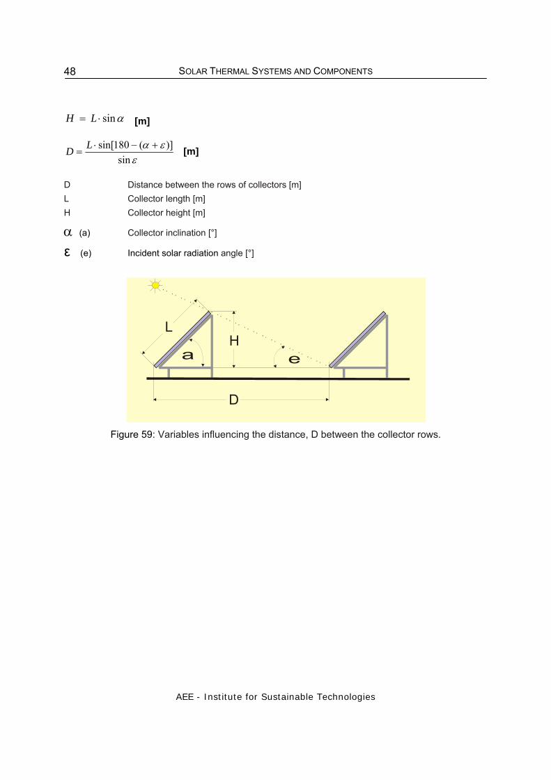
SOLAR THERMAL SYSTEMS AND COMPONENTS
AEE - Institute for Sustainable Technologies
48
αsin⋅= LH [m]
+−⋅
=ε
εαsin
)](180sin[LD [m]
D Distance between the rows of collectors [m] L Collector length [m] H Collector height [m]
α (a) Collector inclination [°]
ε (e) Incident solar radiation angle [°]
a e
LH
D
Figure 59: Variables influencing the distance, D between the collector rows.
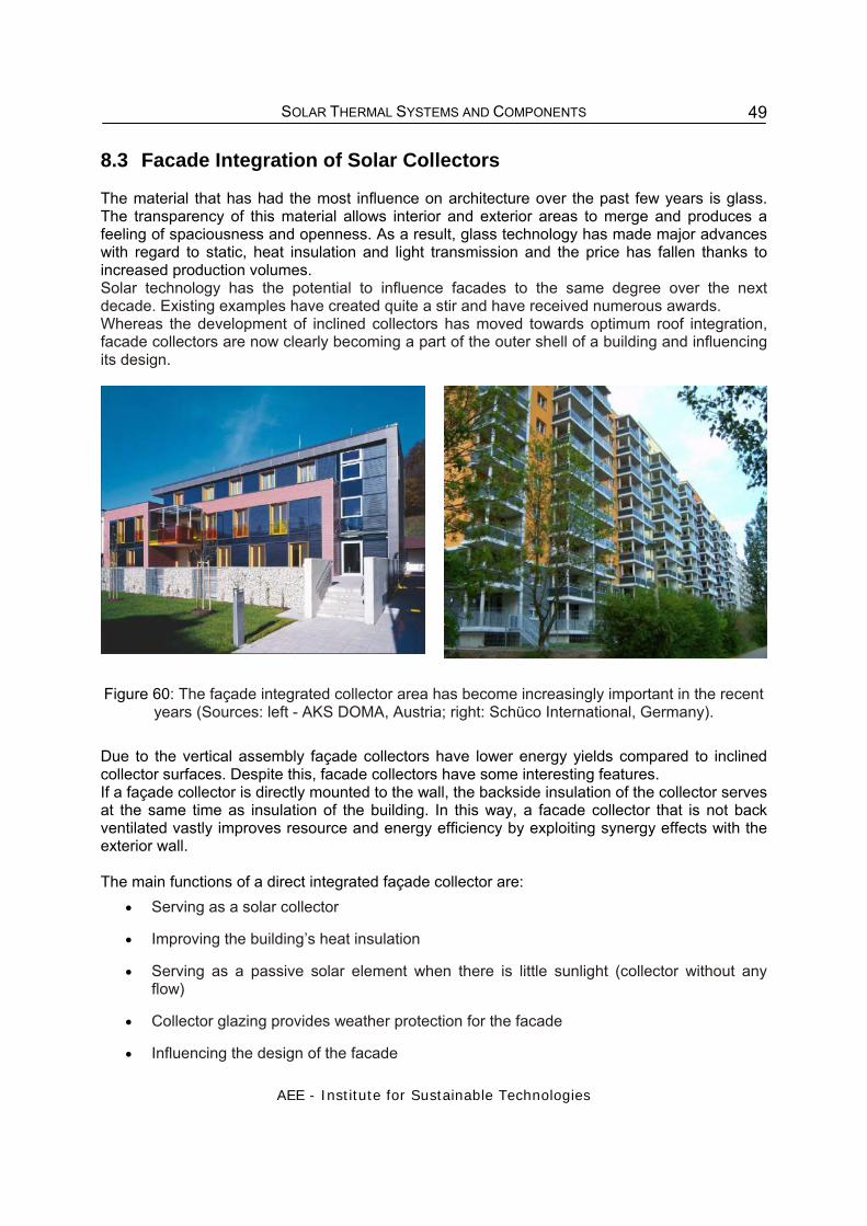
SOLAR THERMAL SYSTEMS AND COMPONENTS
AEE - Institute for Sustainable Technologies
49
8.3 Facade Integration of Solar Collectors The material that has had the most influence on architecture over the past few years is glass. The transparency of this material allows interior and exterior areas to merge and produces a feeling of spaciousness and openness. As a result, glass technology has made major advances with regard to static, heat insulation and light transmission and the price has fallen thanks to increased production volumes. Solar technology has the potential to influence facades to the same degree over the next decade. Existing examples have created quite a stir and have received numerous awards. Whereas the development of inclined collectors has moved towards optimum roof integration, facade collectors are now clearly becoming a part of the outer shell of a building and influencing its design.
Figure 60: The façade integrated collector area has become increasingly important in the recent years (Sources: left - AKS DOMA, Austria; right: Schüco International, Germany).
Due to the vertical assembly façade collectors have lower energy yields compared to inclined collector surfaces. Despite this, facade collectors have some interesting features. If a façade collector is directly mounted to the wall, the backside insulation of the collector serves at the same time as insulation of the building. In this way, a facade collector that is not back ventilated vastly improves resource and energy efficiency by exploiting synergy effects with the exterior wall. The main functions of a direct integrated façade collector are:
• Serving as a solar collector
• Improving the building’s heat insulation
• Serving as a passive solar element when there is little sunlight (collector without any flow)
• Collector glazing provides weather protection for the facade
• Influencing the design of the facade
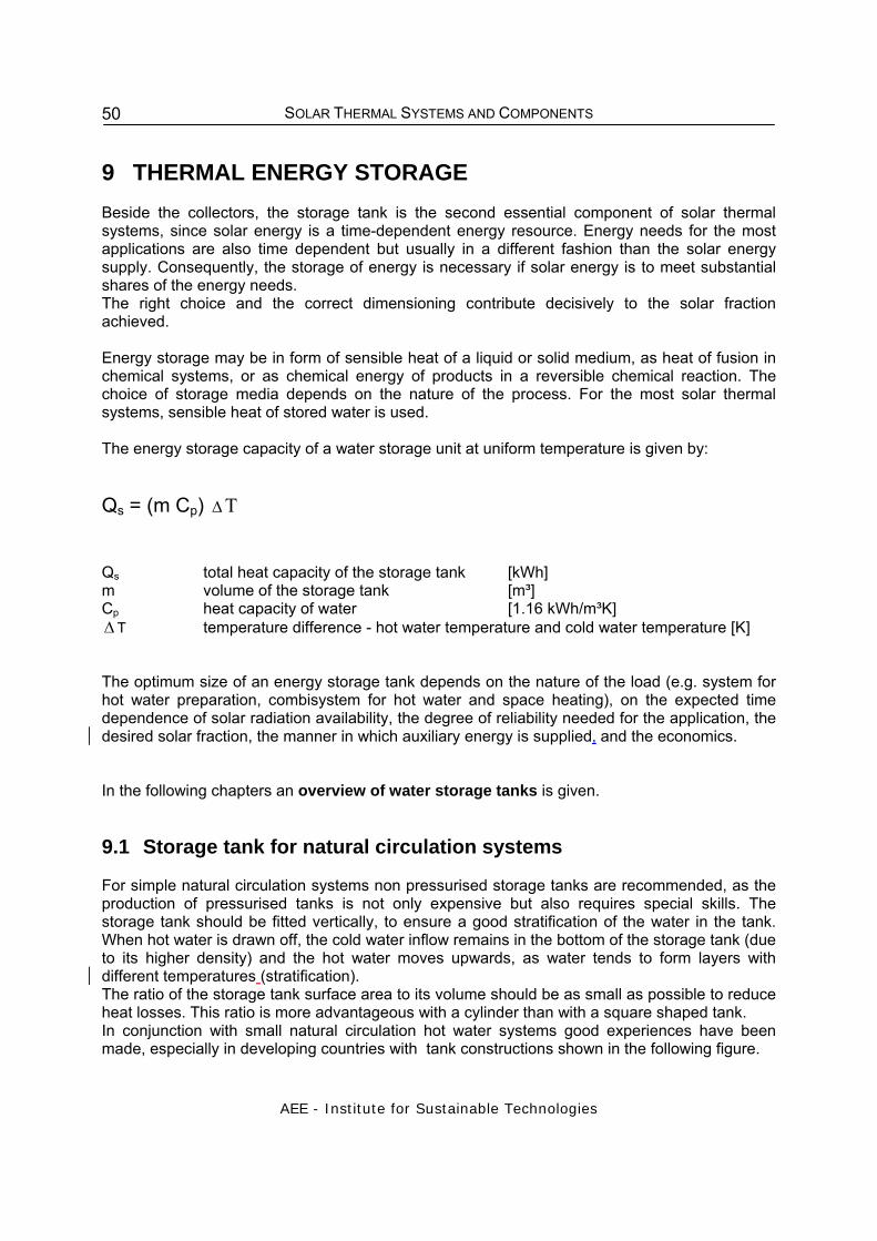
SOLAR THERMAL SYSTEMS AND COMPONENTS
AEE - Institute for Sustainable Technologies
50
9 THERMAL ENERGY STORAGE Beside the collectors, the storage tank is the second essential component of solar thermal systems, since solar energy is a time-dependent energy resource. Energy needs for the most applications are also time dependent but usually in a different fashion than the solar energy supply. Consequently, the storage of energy is necessary if solar energy is to meet substantial shares of the energy needs. The right choice and the correct dimensioning contribute decisively to the solar fraction achieved. Energy storage may be in form of sensible heat of a liquid or solid medium, as heat of fusion in chemical systems, or as chemical energy of products in a reversible chemical reaction. The choice of storage media depends on the nature of the process. For the most solar thermal systems, sensible heat of stored water is used. The energy storage capacity of a water storage unit at uniform temperature is given by: Qs = (m Cp) Δ T
Qs total heat capacity of the storage tank [kWh] m volume of the storage tank [m³] Cp heat capacity of water [1.16 kWh/m³K] Δ T temperature difference - hot water temperature and cold water temperature [K] The optimum size of an energy storage tank depends on the nature of the load (e.g. system for hot water preparation, combisystem for hot water and space heating), on the expected time dependence of solar radiation availability, the degree of reliability needed for the application, the desired solar fraction, the manner in which auxiliary energy is supplied, and the economics. In the following chapters an overview of water storage tanks is given.
9.1 Storage tank for natural circulation systems For simple natural circulation systems non pressurised storage tanks are recommended, as the production of pressurised tanks is not only expensive but also requires special skills. The storage tank should be fitted vertically, to ensure a good stratification of the water in the tank. When hot water is drawn off, the cold water inflow remains in the bottom of the storage tank (due to its higher density) and the hot water moves upwards, as water tends to form layers with different temperatures (stratification). The ratio of the storage tank surface area to its volume should be as small as possible to reduce heat losses. This ratio is more advantageous with a cylinder than with a square shaped tank. In conjunction with small natural circulation hot water systems good experiences have been made, especially in developing countries with tank constructions shown in the following figure.

SOLAR THERMAL SYSTEMS AND COMPONENTS
AEE - Institute for Sustainable Technologies
51
float valve
cold water inlet
hot water outlet
overflow pipe
collector
insulation
Figure 61: Non-pressurised storage tank for simple thermosyphon systems
9.2 Pressurised Storage Tank Pressurized hot water storages are available for thermosyphon systems as well as for pumped solar thermal systems. Usually the hot water tanks for thermosyphon systems are manufactured out of steel or copper. They are available in a range of sizes from 50 to 300 litres.
Figure 62: Hot water storage for a thermosyphon system (Source: Chromagen)
1 Coating
2 Insulation
3 Steel tank
4 Enamel coating
5 Electric heating element
6 Sacrificial anode
7 Thermostat
8 Double Jacket Heat Exchanger
9. Cold water inlet
10. Hot water to user
11. Heat exchanger inlet
12. Heat exchanger outlet
13. Heat Exchanger Safety Valve

SOLAR THERMAL SYSTEMS AND COMPONENTS
AEE - Institute for Sustainable Technologies
52
Figure 63: Hot water storage tanks (left) for direct coupling of evacuated tube collectors
(Source: Easy Solar, South Africa) Usually for systems with forced circulation, upright storage tanks are used, as they ensure a distinct temperature stratification. During the solar charging process, the cold water is heated through a heat exchanger. If hot water is drawn from the highest layer of the storage tank it is replaced by cold water flowing into the lowest layer. The cold water remains at the bottom of the storage tank because its specific gravity is higher than that of hot water. Furthermore, adequate design of the water inlet as well as the installation of baffle plates and deflecting plates helps to avoid turbulence inside the tank. If further hot water is taken from the storage tank the cold water moves upwards like a piston and does not cause significant mixing with the hot water. In addition, this stratification is advantageous for the solar collectors as the collector efficiency is the higher the lower the operating temperature level is. Because of this reason, in high flow-systems the solar heat exchanger should be installed close to the bottom of the tank. If the heat exchanger is dimensioned correctly, it causes only little turbulence in the tank, i.e. at the beginning only the cold layer is heated and the warmer layers are not influenced. Only then when the temperatures of the highest and lowest layers are almost the same, the whole tank contents are heated on evenly. The charging of the storage tank can be done either by internal heat exchangers or by external heat exchangers (plate heat exchangers or ribbed pipe heat exchangers). The installation of the pipes has to be done in such a way that their position does not cause a disturbance of the stratification. Storage tanks used for domestic hot water systems are filled with potable water and must therefore comply with high standards of hygiene. The storage tank has also to withstand corrosion in the presence of oxygen (contained in the potable water). In order to fulfil these requirements the following materials are used for manufacturing domestic hot water tanks:
• Stainless steel
• Enamel-coated steel
• Galvanised steel
• Plastic

SOLAR THERMAL SYSTEMS AND COMPONENTS
AEE - Institute for Sustainable Technologies
53
In buffer tanks, that are usually used for large-scale systems and solar combi-systems the potable water is separated from the storage medium. The storage medium in buffer tanks (energy storage) is also water, but it remains the same water all the time. Because it is a closed vessel without exchange of the medium, the danger of corrosion is very limited and also the pressure in these kind of tanks is low. Due to these reasons the tanks can be made of ordinary steel.
Figure 64: Domestic hot water tank (AUSTRIA EMAIL)
Figure 65: Different types of storage tanks: Domestic hot water tank charged by two coil heat exchangers (left), combi-tank with integrated hot water tank (centre); buffer tank with internal
stratifies (right).

SOLAR THERMAL SYSTEMS AND COMPONENTS
AEE - Institute for Sustainable Technologies
54
Combi-tanks combine a buffer tank with an integrated potable water storage tank (see Figure 56). These kind of storage tanks are used mainly in combi-systems. In this way, the potable water tank can be kept small, even with large volumes of heating water in the buffer tank. Storage tanks with stratification devices
Figure 66: Hot water tanks with stratification devices
(Sources from left to right: Solarklar, TiSun and Solvis)
9.3 Storage Tank Insulation In order to retain the stored energy for as long as possible, an adequate insulation of the storage tank is absolutely necessary. The required minimum insulation is 80 to 120 mm of aluminium coated mineral wool. Special care should be taken that the insulation is adjacent to the storage tank, without any gaps, and that flanges, pipe connections, the electric heating element, thermo-meters, etc. are seamlessly incorporated as far as possible. The losses at these connection points should not be underestimated. In the worst case, they can be many times higher than the losses through the insulation. It is recommended to choose only storage tanks with already completed foam insulation (fluorocarbon-free), or seamlessly adjacent insulation. Another much more inexpensive possibility is to purchase the storage tank without any insulation and to cover it after the installation with a 120 mm insulation of aluminium-coated mineral wool.
9.4 Heat Losses Heat losses of storage tanks are not only caused by poor insulation. Considerable heat losses can also be created by a bad design of the pipe connections to the tank. Special attention

SOLAR THERMAL SYSTEMS AND COMPONENTS
AEE - Institute for Sustainable Technologies
55
should be given to the design of the pipe, where the hot water is extracted, in order to avoid internal circulation in the pipe in times where there is no hot water extraction.
cold water avoids convection SOLUTION: Siphon: falling pipe should be 8 – 12 x pipe diameter
hot
hot
cold cold
coldcold
Heat losses
Figure 67: Heat losses caused by internal flows in the hot water pipe (7, 10)
10 OTHER COMPONENTS
10.1 Expansion Vessel Every closed system with pipes and tanks that is filled with a fluid needs an expansion vessel. Fluids expand and contract with the rise and fall of the temperature inside the system. Without an expansion vessel the weakest part of the system would expand and contract at changes of the temperature in the system. This can lead to a leakages in the system. Another possibility is, that the pressure in the system could rise as far as the safety valve responds. In the following the fluid would leave the system and the pressure in the system would fall till the standstill of the whole system. In order to guarantee the proper function of the system an expansion vessel has to be integrated. The design of an expansion vessel for a solar thermal system with selective absorbers differs a lot from conventional hydraulic circuits without vaporous media. In a solar thermal system the membrane of the MEV must also be resistant against glycol (if glycol is added to the fluid in the collector loop).

SOLAR THERMAL SYSTEMS AND COMPONENTS
AEE - Institute for Sustainable Technologies
56
In essence, the expansion vessel fulfils three functions: uptake of a fluid reserve, uptake of fluid due to thermal expansion in the solar circuit, and uptake of fluid due to vapour formation in the collector. Today mainly membrane expansion vessels (MEV) are used. In most countries there are special standards for MEV’s. In Austria for instance it has to fulfil the Austrian standard ÖN EN 12828, which is in accordance with the standard EN 13831 (standard for closed expansion vessels with membrane for the installation in a water system). MEV’s are closed tanks made of metal. They are separated in two parts by means of a membrane. One compartment is filled with either nitrogen or with air and has to have an initial pressure, which lays about 0.3 bar under the operating pressure of the system in cold condition. This guarantees that volume losses caused by separation of rest-air from the solar circuit are compensated after the filling of the system.
Figure 68: Different states of a membrane expansion vessel (11)
The initial pressure in the expansion vessel department should be controlled with a testing manometer prior to the mounting. If the pressure is too low, air can be filled up with the help of a compressor (service station) or by a pressure pump. Power or pump failure at full incoming solar radiation can cause vapour formation in the collectors. This vapour presses the fluid out of the collectors. In order to control this case, too, the expansion vessel in smaller domestic hot water solar systems is dimensioned so that it can take up the whole fluid contents of the collectors. As a result, even in this case the safety valve will not respond. When the temperature of the absorber drops, the vapour condenses and the system is refilled from the expansion vessel. A guideline value for solar heating systems with a collector area up to 8 m2 and a length of piping up to 20 m is 18to 24 litres; for bigger systems up to 12 m2 collector area a 35 litres expansion vessel can be used. For detailed dimensioning guidelines see chapter “Dimensioning of solar hot water systems”.
10.2 Heat Exchanger In order to avoid calcination, caused by hard water, and to allow the use of antifreeze in the collector loop a heat exchanger is used between collector and the storage. The performance of a heat exchanger should be as high as possible and the pressure drop as low as possible. They should be user friendly and of low maintenance. Heat is generated in the collectors in the primary circuit and a mixture of water and antifreeze is circulating. In the secondary circuit water is circulating (drinking water or water for space heating). The heat should be transferred with a very low difference of temperature to the secondary circuit.
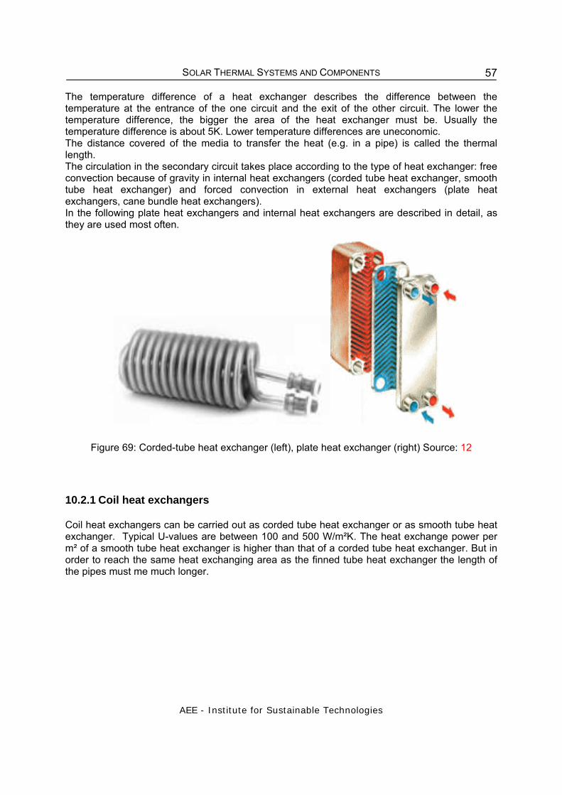
SOLAR THERMAL SYSTEMS AND COMPONENTS
AEE - Institute for Sustainable Technologies
57
The temperature difference of a heat exchanger describes the difference between the temperature at the entrance of the one circuit and the exit of the other circuit. The lower the temperature difference, the bigger the area of the heat exchanger must be. Usually the temperature difference is about 5K. Lower temperature differences are uneconomic. The distance covered of the media to transfer the heat (e.g. in a pipe) is called the thermal length. The circulation in the secondary circuit takes place according to the type of heat exchanger: free convection because of gravity in internal heat exchangers (corded tube heat exchanger, smooth tube heat exchanger) and forced convection in external heat exchangers (plate heat exchangers, cane bundle heat exchangers). In the following plate heat exchangers and internal heat exchangers are described in detail, as they are used most often.
Figure 69: Corded-tube heat exchanger (left), plate heat exchanger (right) Source: 12
10.2.1 Coil heat exchangers
Coil heat exchangers can be carried out as corded tube heat exchanger or as smooth tube heat exchanger. Typical U-values are between 100 and 500 W/m²K. The heat exchange power per m² of a smooth tube heat exchanger is higher than that of a corded tube heat exchanger. But in order to reach the same heat exchanging area as the finned tube heat exchanger the length of the pipes must me much longer.

SOLAR THERMAL SYSTEMS AND COMPONENTS
AEE - Institute for Sustainable Technologies
58
Figure 70: Corded tube heat exchanger ( top);
smooth tube heat exchanger (bottom) Figure 71: Smooth tube heat exchanger
integrated in a domestic hot water storage
Because of its good heat conduction, copper is used to build heat exchangers. The figure above shows a typical application of a coil heat exchanger inside a tank. The advantage of these heat exchangers is the relatively simple construction and a low pressure drop compared to plate heat exchangers. Moreover they are often integrated in the tank by the manufacturer, so there is no additional need for space or installation work. Internal heat exchangers are available as accessories for a certain heat storage tank. The geometry of the heat exchanger is therefore depending on the dimensions of the heat storage tank. External heat exchangers are available in any size and power regardless of the tank. With external heat exchangers more combinations in the hydraulic scheme of the solar thermal system are possible. As a rule of thumb an average logarithmic temperature difference of 10 K is good for the dimensioning of internal heat exchangers:
Smooth tube heat exchanger: approx. 0.2 m² heat exchanger surface per m² collector area
Corded tubes heat exchanger: approx. 0.3 – 0.4 m² heat exchanger surface per m² collector area
The given numbers represent minimum values! Sedimentation of lime Lime sediments reduce the effective heat transfer area significantly. A 2 mm layer leads to a decrease of 20 % of the heat transfer power, a 5 mm layer to more than 40 %. At a long-term run with hard water at above 60 °C leads to calcination, as shown in the figure below.

SOLAR THERMAL SYSTEMS AND COMPONENTS
AEE - Institute for Sustainable Technologies
59
Figure 72: Calcification at a heat exchanger (left picture) and at pipes (middle and right picture) (Source: 13)
Countermeasures
Different countermeasures against calcification are: The maximum temperature should not exceed 60 °C Highly turbulent current in the heat exchanger Pre-treatment of the water 10.2.2 Plate heat exchanger (external) Plate heat exchangers are used for solar thermal systems with solar collector areas of 15 m² and more. They are made of parallel plates. In between the plates there is a counter current of the heat transfer fluids. Due to the special pattern of the plates a turbulent current is generated. This raises the heat transfer. Plate heat exchangers can be soldered or screwed. With screwed plate heat exchangers the number of the plates can be changed, and it is also possible to exchange single plates. At applications up to 300 kW soldered plate heat exchangers are used because of a number of advantages:
• They are very compact compared with ordinary coil heat exchangers. • They save about 85 to 90 % in volume and weight. • Maximum exploitation of the material: the capacity is 25 % higher than the capacity of
screwed plate heat exchangers. • The capacity is 10 times higher compared to the capacity of coil heat exchangers. • Less use of energy, because of a better heat transfer coefficient and consequently a
better temperature difference • Heat transfer still at a temperature difference of 1 K • Possibility of high pressures at operation
Disadvantage: Like at all other external heat exchangers an additional pump is necessary on the secondary side of the heat exchanger

SOLAR THERMAL SYSTEMS AND COMPONENTS
AEE - Institute for Sustainable Technologies
60
10.3 Hot water-mixing valve The maximum storage temperature can be set with the temperature-difference controller. Due to potential calcification, the maximum temperature should not be chosen too high. However, because of hygienic reasons and the possible growth of Legionella bacteria it is recommended that the temperature in the storage tank should not remain below 60°C.
Figure 73: Domestic hot water-mixing valve
In practice, this means a setting of the maximum storage temperature between 60 and 80°C, depending on the degree of water hardness. At this temperature level, the hot water taken from a tap can cause severe scald. Therefore, the installation of a mixing valve (thermostatic mixer), which is set to a temperature of 50 - 55°C is recommended. This ensures that the hot water from the storage tank is always mixed with such an amount of cold water that the water temperature in the pipes does not exceed 55°C. Beside the protection from scald, this valve has also additional advantages: due to the lower temperatures, the distribution losses in the piping and the calcification of the pipes and fittings are reduced.
10.4 Gravity break and safety valve Due to heating of the heat transfer medium in the heat exchanger and cooling down of the collectors overnight, circulation against the intended flow direction due to gravity may occur. To prevent this, a gravity break has to be installed. The safety valve has the function to avoid overpressure, which might occur due to stagnation of the collectors. However, if the expansion tank is dimensioned properly this happens only if the expansion vessel is defective. It is recommended to install a discharge pipe with a collecting

SOLAR THERMAL SYSTEMS AND COMPONENTS
AEE - Institute for Sustainable Technologies
61
container at the outlet of the valve as heat transfer fluid escapes in either liquid form or as vapour when the safety valve opens. The response pressure of safety valves used for solar heating systems is usually between 3 and 6 bar.
Figure 74: Gravity break (14)
Savety valve Lock valve Thermometer andPressure gauge Circulation pumpFilling valve Lock valve Gravity break
Empty valve Expansion vessel
Figure 75: Position of the different components in the return line of the collector loop (7)
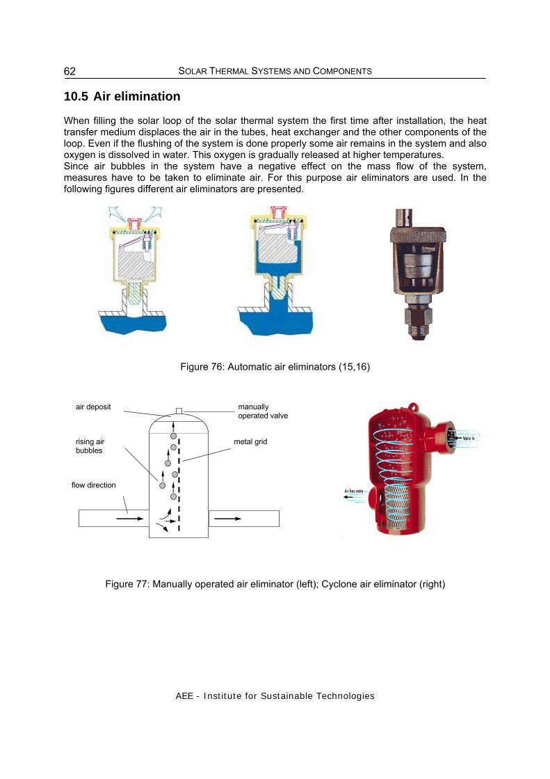
SOLAR THERMAL SYSTEMS AND COMPONENTS
AEE - Institute for Sustainable Technologies
62
10.5 Air elimination When filling the solar loop of the solar thermal system the first time after installation, the heat transfer medium displaces the air in the tubes, heat exchanger and the other components of the loop. Even if the flushing of the system is done properly some air remains in the system and also oxygen is dissolved in water. This oxygen is gradually released at higher temperatures. Since air bubbles in the system have a negative effect on the mass flow of the system, measures have to be taken to eliminate air. For this purpose air eliminators are used. In the following figures different air eliminators are presented.
Figure 76: Automatic air eliminators (15,16)
aufsteigende Luftbläschen
Prallblech (perforiert)
manuelle Entlüftung
Strömungsrichtung des Mediums
abgeschiedene Luft air deposit
rising air bubbles
flow direction
manually operated valve
metal grid
Figure 77: Manually operated air eliminator (left); Cyclone air eliminator (right)

SOLAR THERMAL SYSTEMS AND COMPONENTS
AEE - Institute for Sustainable Technologies
63
10.6 Pumps, safety valves, controller Pumps, safety valves, controllers as well as lock valves are important components of a solar thermal system.
Figure 78: Pump Figure 79: Electronic controller (18)
Figure 80: Thermometer
Figure 81: Flow meter (17)
Figure 82: Safety valve (19)

SOLAR THERMAL SYSTEMS AND COMPONENTS
AEE - Institute for Sustainable Technologies
64
11 SYSTEM CONCEPTS AND APPLICATIONS The basic elements in solar water heaters can be arranged in several system configurations.
11.1 Swimming pool heating The chlorinated pool water is pumped directly through the absorbers by a circulation pump and no heat exchanger is needed. If a filter pump already exists it can be used for the solar circuit, too. In this case, an adequate dimensioning of the pump is most important. Flat-plate collectors can be used for heating of a swimming pool in a sensible way, if besides the pool heating an additional consumer (e.g. domestic hot water, space heating during the cold season) can be supplied. The energy demand of an outdoor pool is mostly influenced by the water temperature. The largest losses are the surface of the pools. That is the reason why the area of the solar system is given as a proportion of the total water surface area. The area of the solar absorber is a function of the pool surface. As a rule of thumb, this should be between 80 and 100% of the pool area for weather conditions in central Europe. Modelling programs such as T-Sol or Polysun exist for a more precise calculation.
Figure 83. Solar heating system for a swimming pool (single circuit system)

SOLAR THERMAL SYSTEMS AND COMPONENTS
AEE - Institute for Sustainable Technologies
65
Figure 84. Plastic absorber for pool water heating
11.2 Thermosyphon systems for hot water preparation Thermo syphon solar systems are widely used in South of Europe, Israel, Australia and North Africa. They are usually used for domestic hot water supply and mounted on flat roofs. These systems consist mainly only of a collector, a tank and the necessary piping. These systems do not need a circulation pump as they take advantage of gravity differences in their operation. The water heated in the collector rises to the top and is replaced by cooler water from the tank (thermo syphon principle). The water in the tank continues to be heated as long as the temperature difference between the collector and the tank is large enough to maintain the circulation. As the buoyant forces are relatively small, pipes with a large cross-section have to be used. In addition, the pipes should be kept as short and straight as possible to achieve the lowest flow resistance.
Figure 85. Gravity-driven domestic hot water system
11.2.1 Direct system with open circulation
In direct systems (open circuit thermosyphon systems) the potable water from the storage tank flows continually through the collectors. This occurs when solar radiation heats the water in the collectors to a temperature above that of the water stored in the tank. A natural circulation („thermosyphon“) is induced by the associated density difference. A direct thermosyphon system must only be installed in non-frost, good quality water areas. Water with high solids content can impair the efficiency of the collector over time due to calcification of the collector waterways. Under frost conditions, collector waterways can freeze and rupture. Open circuit systems can be given limited freeze protection by installing an anti-freeze valve at the bottom of the collector. An anti-freeze valve dribbles water out of the collector when the collector temperature is below 5ºC. An indirect system with a heat exchanger must be installed under either of these conditions. The following table shows water conditions suitable for one-circuit systems. If the supply water exceeds these guidelines then an indirect system is recommended.

SOLAR THERMAL SYSTEMS AND COMPONENTS
AEE - Institute for Sustainable Technologies
66
Table 7: Water conditions suitable for direct systems Source: Solar Edwards, Australia Description Maximum Recommended Level Ph 6.5 - 8.5 TDS 600 mg/l Total Hardness 200 mg/l Chlorides 300 mg/l Magnesium 10 mg/l Calcium 12 mg/l Sodium 150 mg/l Iron 1 mg/l
Figure 86: Simple direct thermosyphon systems, Zimbabwe
absorber
storagetank

SOLAR THERMAL SYSTEMS AND COMPONENTS
AEE - Institute for Sustainable Technologies
67
Figure 87: Principle of a direct system with vertical storage tank Thermosyphon effect The thermo syphon effect has a major influence on three factors: - Height of the tank above the collector - Horizontal or vertical position of the tank - Arrangement of connecting pipes To guarantee an appropriate mass flow the storage tank should be installed 200mm above the upper edge of the collector module. To achieve a good stratification in the storage tank it is recommended to use tanks with vertical position. If the connecting pipes of the system are fitted outside of the tank and outside of the collector box this arrangement works well during the heating up period during daytime. In periods of no radiation and cooler outside temperatures (night time) a reversal in the thermo syphon effect occurs. This reverse flow extracts heat from the storage tank. To solve this problem it is recommended to have the upper connecting pipe (hot water) inside the storage tank and the cold (lower) connecting pipe inside the collector. Don't put one-way valves in the connecting pipes as this causes loss in pressure and therefore a reduction of the thermo syphon effect.
Figure 88: Principle of a direct system with horizontal storage tank
11.2.2 Indirect systems with hydraulic separation
Indirect systems, i.e. it is necessary to separate the collector circuit and the fresh water circuit wherever the water is either very limy or there is a danger of frost. The hydraulic separation of the solar loop from the storage tank water can be fulfilled either by a jacket tank or by a coil heat
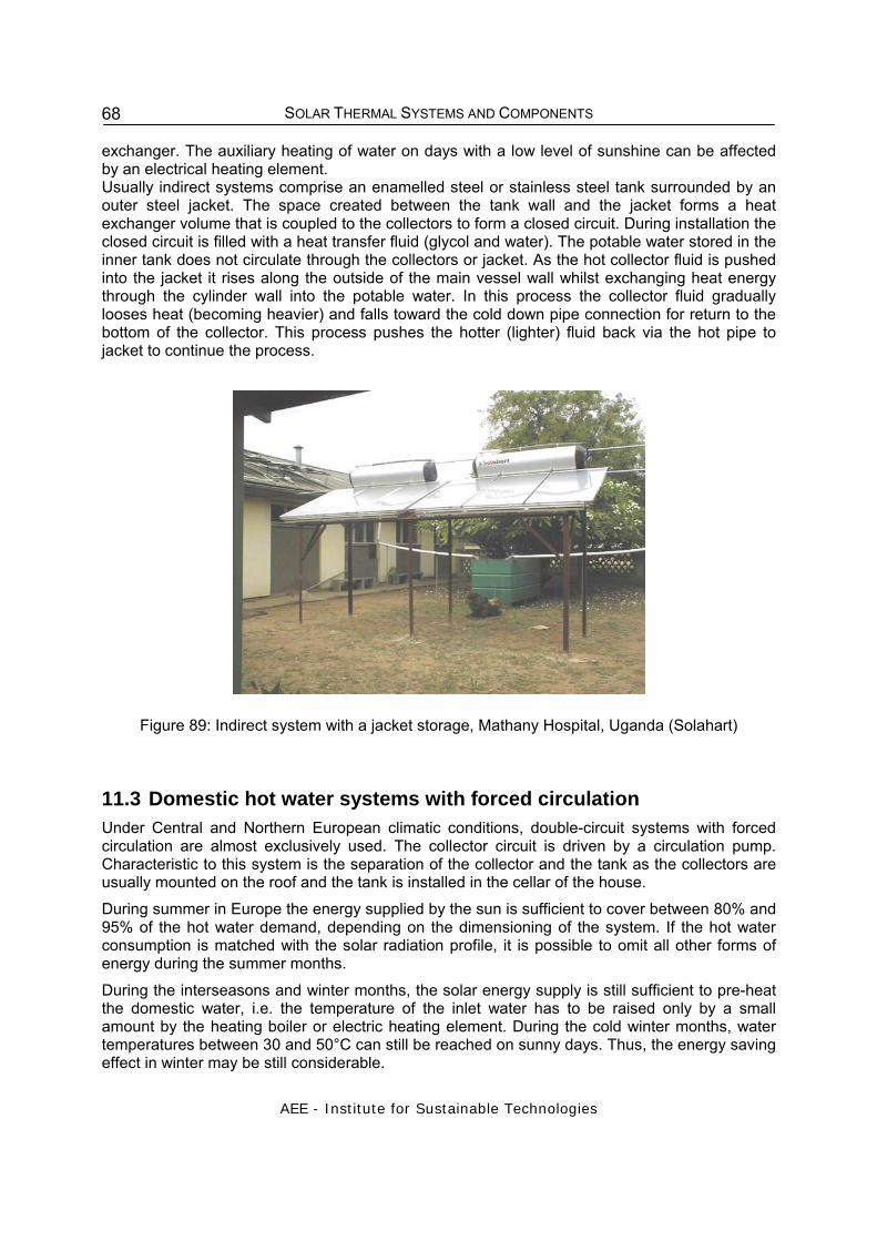
SOLAR THERMAL SYSTEMS AND COMPONENTS
AEE - Institute for Sustainable Technologies
68
exchanger. The auxiliary heating of water on days with a low level of sunshine can be affected by an electrical heating element. Usually indirect systems comprise an enamelled steel or stainless steel tank surrounded by an outer steel jacket. The space created between the tank wall and the jacket forms a heat exchanger volume that is coupled to the collectors to form a closed circuit. During installation the closed circuit is filled with a heat transfer fluid (glycol and water). The potable water stored in the inner tank does not circulate through the collectors or jacket. As the hot collector fluid is pushed into the jacket it rises along the outside of the main vessel wall whilst exchanging heat energy through the cylinder wall into the potable water. In this process the collector fluid gradually looses heat (becoming heavier) and falls toward the cold down pipe connection for return to the bottom of the collector. This process pushes the hotter (lighter) fluid back via the hot pipe to jacket to continue the process.
Figure 89: Indirect system with a jacket storage, Mathany Hospital, Uganda (Solahart)
11.3 Domestic hot water systems with forced circulation Under Central and Northern European climatic conditions, double-circuit systems with forced circulation are almost exclusively used. The collector circuit is driven by a circulation pump. Characteristic to this system is the separation of the collector and the tank as the collectors are usually mounted on the roof and the tank is installed in the cellar of the house. During summer in Europe the energy supplied by the sun is sufficient to cover between 80% and 95% of the hot water demand, depending on the dimensioning of the system. If the hot water consumption is matched with the solar radiation profile, it is possible to omit all other forms of energy during the summer months. During the interseasons and winter months, the solar energy supply is still sufficient to pre-heat the domestic water, i.e. the temperature of the inlet water has to be raised only by a small amount by the heating boiler or electric heating element. During the cold winter months, water temperatures between 30 and 50°C can still be reached on sunny days. Thus, the energy saving effect in winter may be still considerable.

SOLAR THERMAL SYSTEMS AND COMPONENTS
AEE - Institute for Sustainable Technologies
69
Figure 90.: Solar hot water system with forced circulation
Description of a domestic hot water system with forced circulation The incoming solar radiation is converted into heat by the collector (1). This heat is transported by a heat transfer medium (water/anti-freeze mixture) in pipes (2) to a storage tank (3). There, the heat is transferred through a heat exchanger (4) to the domestic water and thus becomes utilisable. The storage tank should be dimensioned in such a way that its volume corresponds to the hot water demand of one to two days. The installation of an additional (e.g. electric) heater (5) ensures that sufficient amounts of hot water are available even during long and continuous periods of overcast weather. The water, which has been cooled in the heat exchanger, then flows back to the collector. The heat transfer medium is circulated by a circulation pump (6). An electronic control (7) ensures that the pump is only turned on when an energy gain from the solar collector is expected, i.e. when the medium in the collector is warmer than the domestic hot water in the tank. Both the storage tank and the pipes are well insulated to avoid unnecessary losses. Additionally, thermometers (8) in the inlet- and outlet pipes belong to the basic equipment of the system. They are preferably installed close to the storage tank. Temperature dependent volume changes in the fluid are compensated by the expansion tank (9), keeping the operating pressure in the system constant. The gravity brake (11) prevents the heat from flowing back to the top if a standstill in the system occurs. A pressure relief valve (10) allows fluid to escape if the system pressure becomes too high. An air escape valve (12) is installed at the highest point, allowing air in the piping to escape. Inlet and outlet taps complete the system. In general, the auxiliary heating of the domestic hot water is performed with a second heat exchanger by a boiler instead of, or in addition to, the electrical auxiliary heating.

SOLAR THERMAL SYSTEMS AND COMPONENTS
AEE - Institute for Sustainable Technologies
70
°C
tank
storage
hot water
cold water
3bar°C/bar
collector area
°C
1
2
3
5
6
7
10
8
4
escape valve
1
fill and empty valve
expansion tank
thermometer
pressure relief valve
thermometer and pressure gaugelock valve
gravity brake
circulation pump
10
8
7
6
5
4
3
2
Figure 91: Hydraulic scheme of a hot water system with forced circulation
11.4 Combisystems for hot water preparation and space heating The demand for solar combi systems, is increasing rapidly. The combination of thermally well-insulated buildings, low-temperature heat supply systems (wall or floor heating systems) and solar systems with a short-term storage, allows high fractional energy savings of the domestic-hot–water and space heating requirements to be met at an acceptable cost. In comparison to systems with a seasonal storage, the costs of which are currently not justifiable for single-family houses, this combination provides a more cost-effective system. The solar energy available in central Europe in summer is more than twice that available in winter. Virtually, the opposite applies to the energy demand for space heating. In comparison to a hot-water supply, the heating load is dependent upon the outside temperature. Measurements of solar radiation and temperature in the transitional periods (September - October and March -

SOLAR THERMAL SYSTEMS AND COMPONENTS
AEE - Institute for Sustainable Technologies
71
May) clearly show that solar radiation availability is relatively high at the beginning and the end of the space heating season. Even on winter days, energy demand and solar radiation are partially related. The space heating demand on cloudy days is lower than on cold, clear, winter days where the solar collectors are able to deliver more energy. The figure below shows the solar radiation on a horizontal plane in Graz, Austria. It can be seen that, at this latitude, not only are there strong seasonal variations in radiation, but also that weather patterns cause radiation levels to change quite widely on a daily, or even hourly, basis. In order to make efficient use of the available solar energy supply - it is necessary to even out these fluctuations - by means of either auxiliary heating or energy storage systems, to ensure a comfortable room temperature.
Jan Feb Mar Apr May Jun Jul Aug Sep Oct Nov Dec Jan
Total: 1126.91kWh/m²
0,0
0,9
1,8
2,7
3,6
4,5
5,4
6,3
7,2
8,1
9,0
[kWh/m²] Solar-Radiation
Figure 92: Solar radiation on a horizontal plane in Graz, Austria
A basic requirement for all new buildings is the efficient use of energy through a high insulation standard. Low-energy houses, with an annual space heating demand of less than 60 kWh per square meter of habitable space, offer the ideal opportunity for solar space heating. A low-temperature heat supply system with low inlet temperature is an additional requirement favourable for solar space heating. The wide fluctuations in incident solar radiation shown in the figure above can be evened out by the use of a heat storage system. The following opportunities are available for balancing out the variations in energy supply and demand:
• Hourly, or even overnight, variations can be simply compensated for by the thermal capacitance of the heat supply system (e.g., floor heating) or the heat storage mass of the building.
• If insufficient solar radiation is available for several days, a small thermal storage volume
can be used to make up the difference.
• Seasonal variations in solar energy supply can only be compensated by the use of a seasonal storage. In recent years several systems have shown that it is possible to store summer heat in large water reservoirs (50 - 100 m3 for a single-family house) for use in winter. In the interest of cost, solar systems with a seasonal storage will first be used in

SOLAR THERMAL SYSTEMS AND COMPONENTS
AEE - Institute for Sustainable Technologies
72
large systems in conjunction with district heating, on the basis that specific storage costs decrease drastically with increasing size. Interesting examples available in Sweden, Denmark and Germany indicate an promising way forward.
For single- and multi-family dwellings, the concept of partial solar space heating (solar energy and auxiliary energy source) is more interesting for economic reasons. Several thousand solar combisystems have been erected in Austria in single-family homes. since the early 90’s. In the recent years it has, however, also been possible to construct numerous solar combisystems in hotels and multi-family dwellings.
Biomassboiler
Colle
ctor
Hot water
Cold water
Space heating
Figure 93: Hydraulic scheme of a solar combisystem for a single family house
ENERGY SUPPLY TRANSFER, STORAGE, CONTROL AND DISTRIBUTION LOAD
M
S A H1 DHW
Figure 94: Advanced solar combisystem with a pellet burner integrated in the storage tank. Hydraulic scheme (left) /3/ and storage tank with integrated pellet burner (right, Source:
Solarfocus)

SOLAR THERMAL SYSTEMS AND COMPONENTS
AEE - Institute for Sustainable Technologies
73
Collec
tor Fiel
d
Boiler
Heat Store
Cold Water
Cold Water
Cold Water
Hot Water
Hot Water
Hot Water
Figure 95: Hydraulic scheme of a solar combisystem for a multi-family house
11.5 District heating Solar assisted district heating systems are used to provide low temperature heat (below 150°C) on a diurnal or a seasonal timeline. Such technologies include at present large-module (flat plate) collectors mounted on roofs or on the ground and different kinds of large heat storage systems. Common water-filled steel tanks are used as diurnal storage, while a number of different storage technologies are used as seasonal storages, e.g. large water-filled tanks and pits in ground, borehole storages in ground and rock, as well as aquifers. A number of these technologies are already applied in demonstration projects mainly in the northern parts of Europe, e.g. Sweden, Denmark, Germany and Austria. The largest plant so far in Europe is designed with 13 MWth (18 000 m²) solar collectors. The plant is located in Marstal in Denmark. Austria Since the beginning of the 1980s about 500 biomass district heating networks have been built in Austria and more of these types of plants are continuously being built and successfully operated. Especially due to the amount of wood available in Austria, these plants are considered to be interesting and also highly acceptable regarding the independence from fossil energy imports. Several of these central biomass plants have been equipped with solar collector arrays, acting as an auxiliary heat supplier.

SOLAR THERMAL SYSTEMS AND COMPONENTS
AEE - Institute for Sustainable Technologies
74
0
2
4
6
8
10
12
14
19
79
19
80
19
81
19
82
19
83
19
84
19
85
19
86
19
87
19
88
19
89
19
90
19
91
19
92
19
93
19
94
19
95
19
96
19
97
19
98
19
99
20
00
20
01
20
02
20
03
20
04
20
05
20
06
20
07
No of plants
Closed (12)
OTH (14)
ES (13)
AT (14)
CH (7)
GR (14)
DE (18)
NL (8)
DK (10)
SE (22)
Figure 96: Large-scale solar heating and cooling plants in Europe at the end of 2007, Source: Dalenbäck 2007
Up until now, 18 solar assisted biomass district heating networks have been erected in Austria with installed capacities between 245 and 875 kWth corresponding to collector areas of 350 - 1250m². These systems offer for whole villages the possibility to switch to a 100% heat supply based on renewable energies. The largest plant so far with a capacity of about 1 MWth (1 400 m²) is placed on the roof of the UPC arena in Graz. This system is coupled with the district-heating network of the city of Graz. Several more systems of this size were in the design phase since 2006.
Figure 97: Left picture: Solar assisted biomass district heating plant, Eibiswald with an installed capacity of 875 kWth, (1250 m² collector array). Right picture: District heating plant in Graz with
an installed capacity of 980 kWth, (1400 m² collector array). Source: S.O.L.I.D.
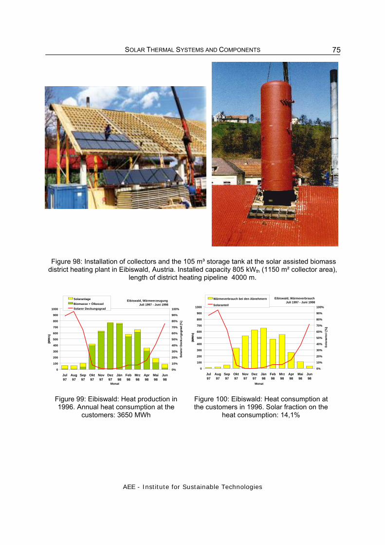
SOLAR THERMAL SYSTEMS AND COMPONENTS
AEE - Institute for Sustainable Technologies
75
Figure 98: Installation of collectors and the 105 m³ storage tank at the solar assisted biomass district heating plant in Eibiswald, Austria. Installed capacity 805 kWth (1150 m² collector area),
length of district heating pipeline 4000 m.
Eibiswald, Wärmeerzeugung Juli 1997 - Juni 1998
0
100
200
300
400
500
600
700
800
900
1000
Jul97
Aug97
Sep97
Okt97
Nov97
Dez97
Jän98
Feb98
Mrz98
Apr98
Mai98
Jun98
Monat
0%
10%
20%
30%
40%
50%
60%
70%
80%
90%
100%
SolaranlageBiomasse + ÖlkesselSolarer Deckungsgrad
Eibiswald, Wärmeverbrauch Juli 1997 - Juni 1998
0
100
200
300
400
500
600
700
800
900
1000
Jul97
Aug97
Sep97
Okt97
Nov97
Dez97
Jän98
Feb98
Mrz98
Apr98
Mai98
Jun98
Monat
0%
10%
20%
30%
40%
50%
60%
70%
80%
90%
100%
Wärmeverbrauch bei den Abnehmern
Solaranteil
Figure 99: Eibiswald: Heat production in 1996. Annual heat consumption at the
customers: 3650 MWh
Figure 100: Eibiswald: Heat consumption at the customers in 1996. Solar fraction on the
heat consumption: 14,1%
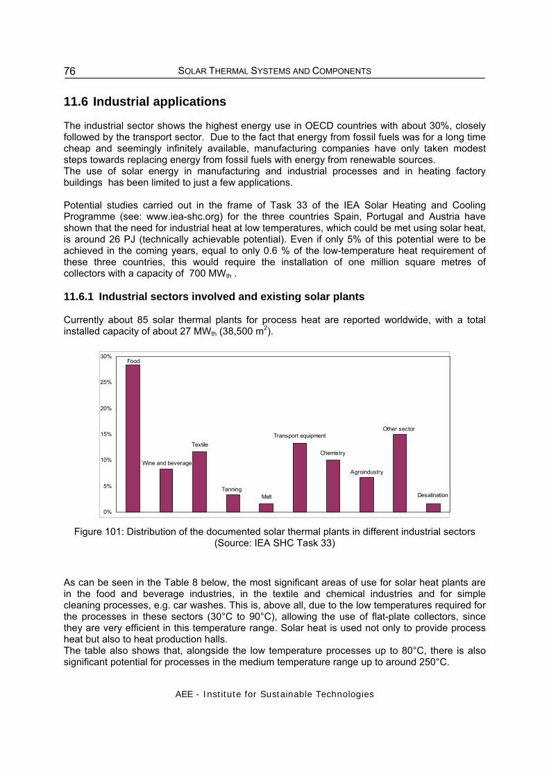
SOLAR THERMAL SYSTEMS AND COMPONENTS
AEE - Institute for Sustainable Technologies
76
11.6 Industrial applications The industrial sector shows the highest energy use in OECD countries with about 30%, closely followed by the transport sector. Due to the fact that energy from fossil fuels was for a long time cheap and seemingly infinitely available, manufacturing companies have only taken modest steps towards replacing energy from fossil fuels with energy from renewable sources. The use of solar energy in manufacturing and industrial processes and in heating factory buildings has been limited to just a few applications. Potential studies carried out in the frame of Task 33 of the IEA Solar Heating and Cooling Programme (see: www.iea-shc.org) for the three countries Spain, Portugal and Austria have shown that the need for industrial heat at low temperatures, which could be met using solar heat, is around 26 PJ (technically achievable potential). Even if only 5% of this potential were to be achieved in the coming years, equal to only 0.6 % of the low-temperature heat requirement of these three countries, this would require the installation of one million square metres of collectors with a capacity of 700 MWth . 11.6.1 Industrial sectors involved and existing solar plants Currently about 85 solar thermal plants for process heat are reported worldwide, with a total installed capacity of about 27 MWth (38,500 m2).
Agroindustry
Food
Wine and beverage
Tanning
Textile
Malt
Transport equipment
Chemistry
Other sector
Desalination
0%
5%
10%
15%
20%
25%
30%
Figure 101: Distribution of the documented solar thermal plants in different industrial sectors
(Source: IEA SHC Task 33)
As can be seen in the Table 8 below, the most significant areas of use for solar heat plants are in the food and beverage industries, in the textile and chemical industries and for simple cleaning processes, e.g. car washes. This is, above all, due to the low temperatures required for the processes in these sectors (30°C to 90°C), allowing the use of flat-plate collectors, since they are very efficient in this temperature range. Solar heat is used not only to provide process heat but also to heat production halls. The table also shows that, alongside the low temperature processes up to 80°C, there is also significant potential for processes in the medium temperature range up to around 250°C.

SOLAR THERMAL SYSTEMS AND COMPONENTS
AEE - Institute for Sustainable Technologies
77
Table 8: Industrial sectors and processes with the greatest potential for solar thermal uses
Industrial sector Process Temperature level [°C] Food and beverages drying
washing pasteurising boiling sterilising heat treatment
30 - 90 40 – 80
80 – 110 95 – 105 140 – 150
40 – 60 Textile industry washing
bleaching dyeing
40 –80 60 – 100 100 – 160
Chemical industry boiling distilling various chemical processes
95 – 105 110 – 300 120 - 180
All sectors pre-heating of boiler feed water heating of production halls
30 – 100 30 – 80
11.6.2 Development of medium-temperature collectors To be able to provide heat for the whole medium-temperature range from 80° to 250°C for industrial processes at a reasonable price, it is necessary to optimise and further develop medium temperature collectors. Therefore three categories of medium-temperature collectors are being developed and tested at the moment. 11.6.2.1 Improved flat-plate collectors
There are a number of different development possibilities for flat-plate collectors that would enable them to be used in applications between 80°C and 120°C. In the first instance it is necessary to reduce the thermal losses of the collectors without losing too much optical efficiency. This can be achieved, for example, by using multiply glazed flat-plate collectors with anti-reflective glass, or using a hermetically sealed flat-plate design where the collector is filled with a noble gas, or by the development of evacuated flat-plate collector designs. The figure below shows the efficiency curves for single, double and triple-glazed collectors covered with newly developed anti-reflective glass.

SOLAR THERMAL SYSTEMS AND COMPONENTS
AEE - Institute for Sustainable Technologies
78
0
0.1
0.2
0.3
0.4
0.5
0.6
0.7
0.8
0.9
0 0.05 0.1 0.15
(Tm-Ta)/G in Km²/W
effic
ienc
y (b
ased
on
aper
ture
are
a)
1 AR
2 AR
3 AR
standard flat-platecollector
operating temperature 80° to 120°C
Figure 102: Comparison of the efficiency curves for a standard flat-plate collector (normal solar glass) and the curves for single, double and triple- anti-reflective (AR) glazed collectors (G=800
W/m²). Source: M. Rommel, Fraunhofer ISE.
11.6.2.2 Concentrating flat-plate and evacuated tube collectors
A further possibility for the development of medium temperature collectors is to reduce thermal losses in the collector by concentrating the solar rays and therefore reducing the surface area. CPC collectors based on this principle are being developed in Portugal (AoSol and INETI) and Austria (Solarfocus), for example. The concentration factor is around 2. For this reason, no sun-tracking devices are needed. The figure shows the construction of a collector made by Solarfocus, Austria, in which the absorber fins, which are absorbing on both surfaces, are mounted in the reflector troughs perpendicular to the aperture opening.
Figure 103: CPC collector : 1,12 – 1,7 x, acceptance angle: 37 – 56° (Source: Ao Sol Portugal)
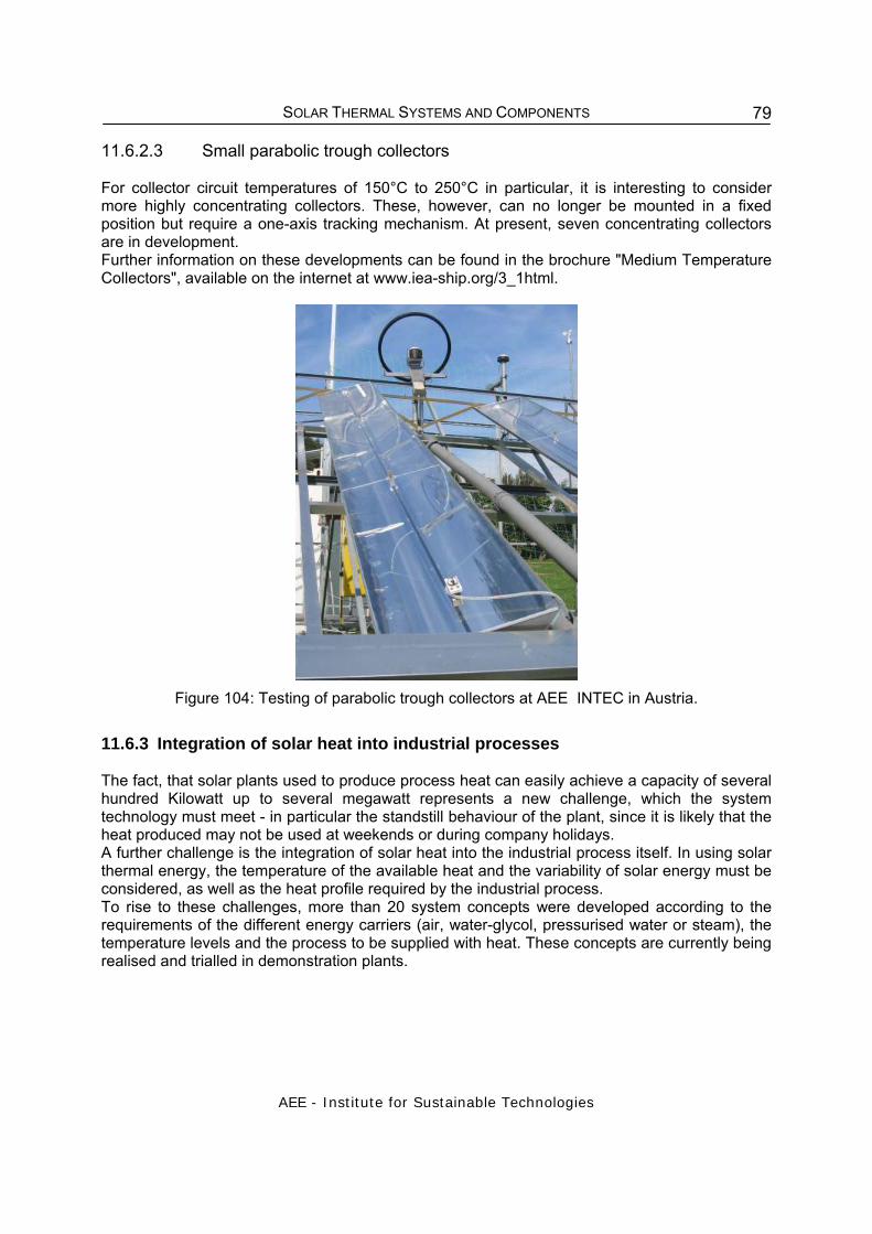
SOLAR THERMAL SYSTEMS AND COMPONENTS
AEE - Institute for Sustainable Technologies
79
11.6.2.3 Small parabolic trough collectors For collector circuit temperatures of 150°C to 250°C in particular, it is interesting to consider more highly concentrating collectors. These, however, can no longer be mounted in a fixed position but require a one-axis tracking mechanism. At present, seven concentrating collectors are in development. Further information on these developments can be found in the brochure "Medium Temperature Collectors", available on the internet at www.iea-ship.org/3_1html.
Figure 104: Testing of parabolic trough collectors at AEE INTEC in Austria.
11.6.3 Integration of solar heat into industrial processes The fact, that solar plants used to produce process heat can easily achieve a capacity of several hundred Kilowatt up to several megawatt represents a new challenge, which the system technology must meet - in particular the standstill behaviour of the plant, since it is likely that the heat produced may not be used at weekends or during company holidays. A further challenge is the integration of solar heat into the industrial process itself. In using solar thermal energy, the temperature of the available heat and the variability of solar energy must be considered, as well as the heat profile required by the industrial process. To rise to these challenges, more than 20 system concepts were developed according to the requirements of the different energy carriers (air, water-glycol, pressurised water or steam), the temperature levels and the process to be supplied with heat. These concepts are currently being realised and trialled in demonstration plants.

SOLAR THERMAL SYSTEMS AND COMPONENTS
AEE - Institute for Sustainable Technologies
80
Figure 105: System concepts (generic systems) for the integration of solar heat into industrial processes
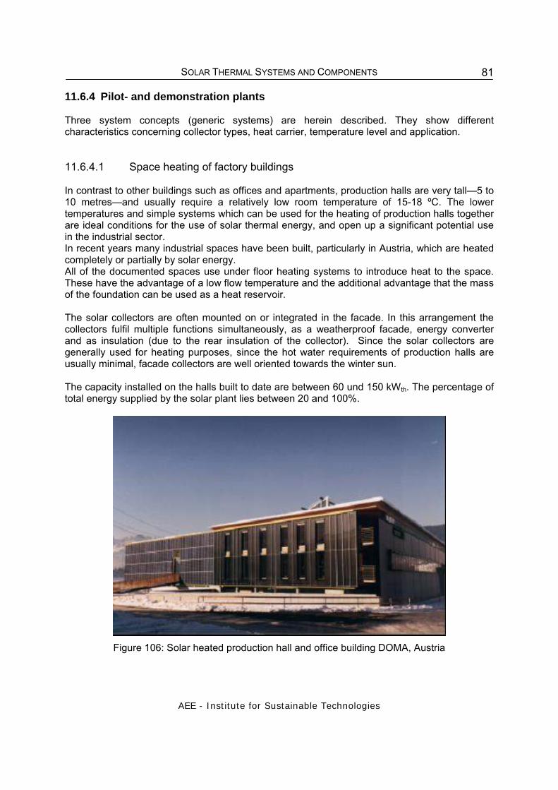
SOLAR THERMAL SYSTEMS AND COMPONENTS
AEE - Institute for Sustainable Technologies
81
11.6.4 Pilot- and demonstration plants Three system concepts (generic systems) are herein described. They show different characteristics concerning collector types, heat carrier, temperature level and application. 11.6.4.1 Space heating of factory buildings In contrast to other buildings such as offices and apartments, production halls are very tall—5 to 10 metres—and usually require a relatively low room temperature of 15-18 ºC. The lower temperatures and simple systems which can be used for the heating of production halls together are ideal conditions for the use of solar thermal energy, and open up a significant potential use in the industrial sector. In recent years many industrial spaces have been built, particularly in Austria, which are heated completely or partially by solar energy. All of the documented spaces use under floor heating systems to introduce heat to the space. These have the advantage of a low flow temperature and the additional advantage that the mass of the foundation can be used as a heat reservoir. The solar collectors are often mounted on or integrated in the facade. In this arrangement the collectors fulfil multiple functions simultaneously, as a weatherproof facade, energy converter and as insulation (due to the rear insulation of the collector). Since the solar collectors are generally used for heating purposes, since the hot water requirements of production halls are usually minimal, facade collectors are well oriented towards the winter sun. The capacity installed on the halls built to date are between 60 und 150 kWth. The percentage of total energy supplied by the solar plant lies between 20 and 100%.
Figure 106: Solar heated production hall and office building DOMA, Austria
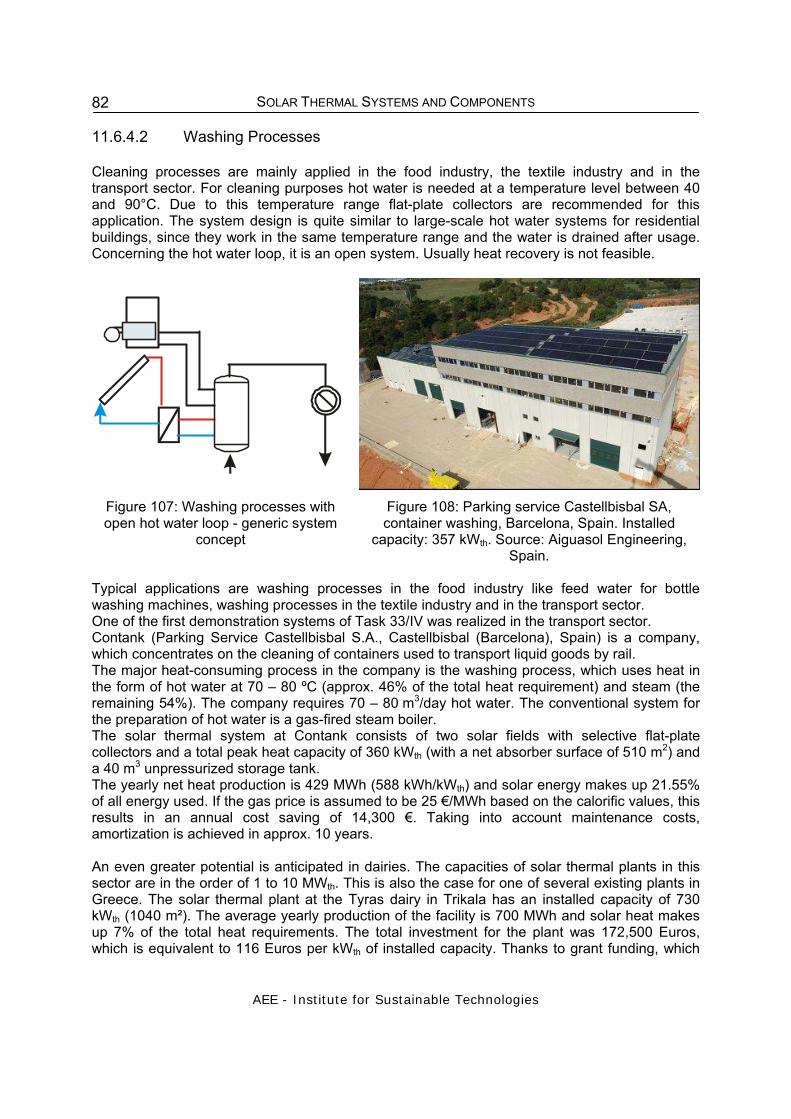
SOLAR THERMAL SYSTEMS AND COMPONENTS
AEE - Institute for Sustainable Technologies
82
11.6.4.2 Washing Processes
Cleaning processes are mainly applied in the food industry, the textile industry and in the transport sector. For cleaning purposes hot water is needed at a temperature level between 40 and 90°C. Due to this temperature range flat-plate collectors are recommended for this application. The system design is quite similar to large-scale hot water systems for residential buildings, since they work in the same temperature range and the water is drained after usage. Concerning the hot water loop, it is an open system. Usually heat recovery is not feasible.
Figure 107: Washing processes with open hot water loop - generic system
concept
Figure 108: Parking service Castellbisbal SA, container washing, Barcelona, Spain. Installed
capacity: 357 kWth. Source: Aiguasol Engineering, Spain.
Typical applications are washing processes in the food industry like feed water for bottle washing machines, washing processes in the textile industry and in the transport sector. One of the first demonstration systems of Task 33/IV was realized in the transport sector. Contank (Parking Service Castellbisbal S.A., Castellbisbal (Barcelona), Spain) is a company, which concentrates on the cleaning of containers used to transport liquid goods by rail. The major heat-consuming process in the company is the washing process, which uses heat in the form of hot water at 70 – 80 ºC (approx. 46% of the total heat requirement) and steam (the remaining 54%). The company requires 70 – 80 m3/day hot water. The conventional system for the preparation of hot water is a gas-fired steam boiler. The solar thermal system at Contank consists of two solar fields with selective flat-plate collectors and a total peak heat capacity of 360 kWth (with a net absorber surface of 510 m2) and a 40 m3 unpressurized storage tank. The yearly net heat production is 429 MWh (588 kWh/kWth) and solar energy makes up 21.55% of all energy used. If the gas price is assumed to be 25 €/MWh based on the calorific values, this results in an annual cost saving of 14,300 €. Taking into account maintenance costs, amortization is achieved in approx. 10 years. An even greater potential is anticipated in dairies. The capacities of solar thermal plants in this sector are in the order of 1 to 10 MWth. This is also the case for one of several existing plants in Greece. The solar thermal plant at the Tyras dairy in Trikala has an installed capacity of 730 kWth (1040 m²). The average yearly production of the facility is 700 MWh and solar heat makes up 7% of the total heat requirements. The total investment for the plant was 172,500 Euros, which is equivalent to 116 Euros per kWth of installed capacity. Thanks to grant funding, which

SOLAR THERMAL SYSTEMS AND COMPONENTS
AEE - Institute for Sustainable Technologies
83
covered 50% of the costs, the short amortization time required by the industrial sector was achieved.
Figure 109: A view of the collector field at the Tyras dairy, Trikala, Greece
Source: A. Aidonis, CRES
11.6.4.3 Distilling and chemical processes
For industrial processes where temperatures between 120°C and 250 °C are needed, concentrating solar collectors, such as parabolic trough collectors have to be used. The heat carrier in these systems is either pressurized hot water or steam.
steam
Figure 110: Steam production via a flashing process - generic system
concept
Figure 111: El NASR Pharmaceutical Chemicals, Egypt. Installed capacity: 1,33 MWth
Source: Fichtner Solar GmbH. Germany.
The Egyptian New & Renewable Energy Authority (NREA) issued an international tender to build a 1.3 t/hr pilot solar steam plant using parabolic trough collectors at a site just outside Cairo. The project was financed by the African Development Bank. The plant’s 144 parabolic concentrators are arranged in four parallel loops and provide a net reflective area of 1,900 m². The steam is produced by the reduction of the pressure of the water

SOLAR THERMAL SYSTEMS AND COMPONENTS
AEE - Institute for Sustainable Technologies
84
in the collector loop, via a flashing valve and is delivered to an existing saturated steam network operating at 7.5 bar.
Chapter 11 - References: /1/ Weiss, W. et.al: Solar Heating Worldwide, Markets and contribution to the energy supply,
IEA Solar Heating and Cooling Programme, Internal paper 2005. /2/ Müller, T. et. al.: PROMISE – Produzieren mit Sonnenenergie, Projekt im Rahmen der
Programmlinien „Fabrik der Zukunft“ des Bundesministeriums für Verkehr, Innovation und Technologie, Endbericht, Gleisdorf, 2004
/3/ Rommel, M.: Prozesswärmekollektoren – Aktuelle Entwicklungen im
Mitteltemperaturbereich bis 250°C, in: erneuerbare energie 3-2005, Gleisdorf, 2005. /4/ Jähnig, D., Weiss, W.: Solar beheizte Industriehallen in Österreich, in: erneuerbare
energie 3-2005, Gleisdorf, 2005. /5/ Schweiger, H. et. al.: 360 kW solarthermische Anlage für einen industriellen
Waschprozess, in: erneuerbare energie 3-2005, Gleisdorf, 2005. /6/ Aidonis, A.: Internal paper – status Trikala dairy, Task 33/IV, 2005. Further information: www.iea-shc.org www.aee-intec.at www.iea-ship.org
11.7 Solar cooling and air conditioning This chapter is a summary of the forum "Solar assisted Air-Conditioning of Buildings" held at the convention Intersolar 2002 in Freiburg, Germany. Sunny summer days are beautiful, yet in the office a hot day can be altogether stressful. Because productivity can suffer under such conditions, more and more buildings are being fitted with air-conditioning systems. This is where solar air conditioning comes in: The summer sun, which heats up offices, also delivers the energy to cool them. The thermal use of solar energy offers itself: Days that have the greatest need for cooling are also the very same days that offer the maximum possible solar energy gain. The demand for air conditioning in offices, hotels, laboratories or public buildings such as museums is considerable. This is true not only in southern Europe, but also in middle Europe. Under adequate conditions, solar and solar-assisted air conditioning systems can be reasonable alternatives to conventional air conditioning systems. Such systems have advantages over those that use problematic coolants (CFCs), not to mention the incidental CO2 emissions that are taking on increasingly critical values. 11.7.1 What is Solar Air Conditioning?
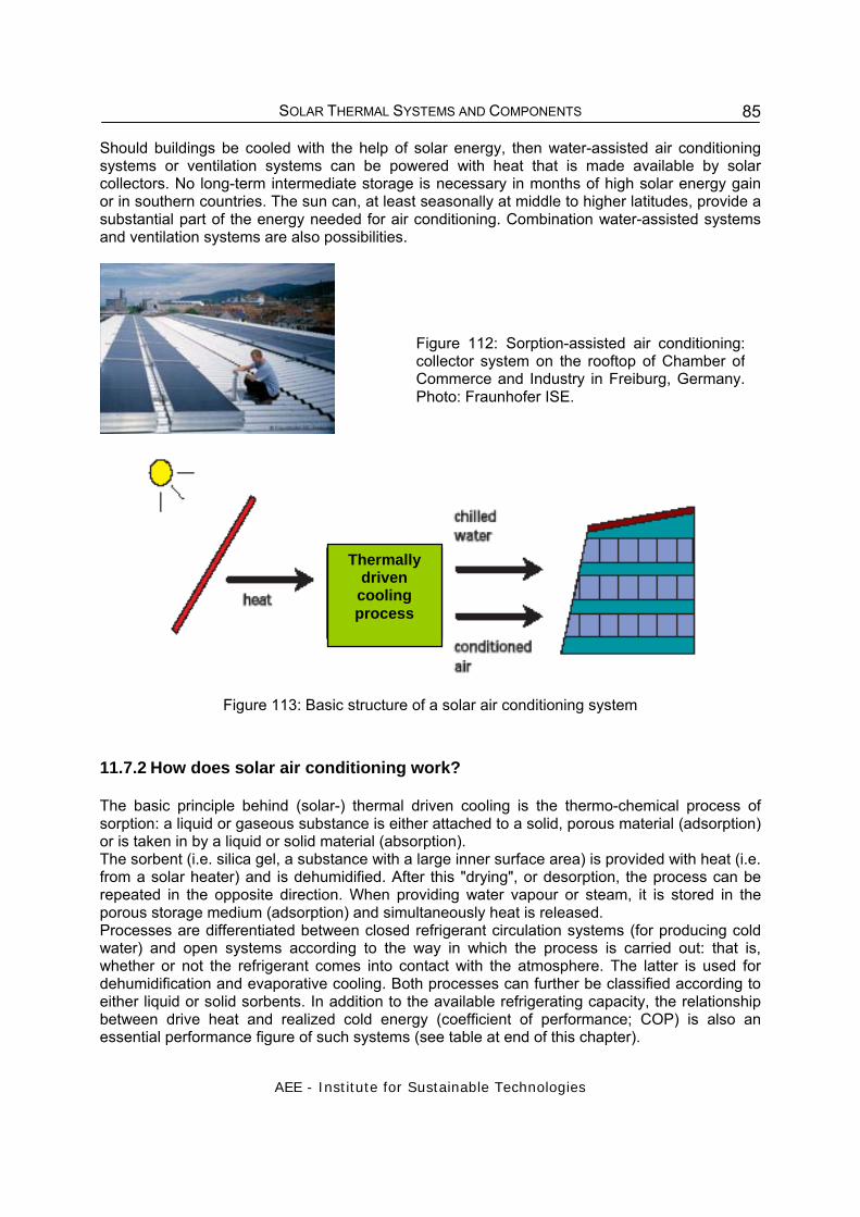
SOLAR THERMAL SYSTEMS AND COMPONENTS
AEE - Institute for Sustainable Technologies
85
Should buildings be cooled with the help of solar energy, then water-assisted air conditioning systems or ventilation systems can be powered with heat that is made available by solar collectors. No long-term intermediate storage is necessary in months of high solar energy gain or in southern countries. The sun can, at least seasonally at middle to higher latitudes, provide a substantial part of the energy needed for air conditioning. Combination water-assisted systems and ventilation systems are also possibilities.
Figure 112: Sorption-assisted air conditioning: collector system on the rooftop of Chamber of Commerce and Industry in Freiburg, Germany. Photo: Fraunhofer ISE.
Figure 113: Basic structure of a solar air conditioning system
11.7.2 How does solar air conditioning work?
The basic principle behind (solar-) thermal driven cooling is the thermo-chemical process of sorption: a liquid or gaseous substance is either attached to a solid, porous material (adsorption) or is taken in by a liquid or solid material (absorption). The sorbent (i.e. silica gel, a substance with a large inner surface area) is provided with heat (i.e. from a solar heater) and is dehumidified. After this "drying", or desorption, the process can be repeated in the opposite direction. When providing water vapour or steam, it is stored in the porous storage medium (adsorption) and simultaneously heat is released. Processes are differentiated between closed refrigerant circulation systems (for producing cold water) and open systems according to the way in which the process is carried out: that is, whether or not the refrigerant comes into contact with the atmosphere. The latter is used for dehumidification and evaporative cooling. Both processes can further be classified according to either liquid or solid sorbents. In addition to the available refrigerating capacity, the relationship between drive heat and realized cold energy (coefficient of performance; COP) is also an essential performance figure of such systems (see table at end of this chapter).
Thermally driven cooling process

SOLAR THERMAL SYSTEMS AND COMPONENTS
AEE - Institute for Sustainable Technologies
86
11.7.3 Absorption refrigeration machines Closed absorption refrigeration machines with liquid sorbent (water-lithium bromide) are most often operated in combination with heat and power generation (cogeneration) (i.e. with block unit heating power plants, district heating), but can also be assisted by vacuum tube solar collectors (operating temperature above 80 °C). With a single-step process the COP is 0.6-0.75, or up to 1.2 for a two-step process. A market overview is available from the German Consortium for Economical and Environmentally Friendly Energy Use (Arbeitsgemeinschaft für sparsamen und umweltfreundlichen Energieverbrauch (ASUE). 11.7.4 Adsorption refrigeration machines Closed processes with solid sorbents work with so-called adsorption refrigeration machines (operating temperatures 60° - 95°; COP = 0.3 - 0.7). Solar energy can easily be used in the form of vacuum tube or flat plate collectors. A pilot system used for a laboratory's climate control at the University Clinic of Freiburg is fitted with tube collectors; the Fraunhofer ISE also took part in its scientific conception. The refrigerating machine is composed of two adsorbers, one an evaporator and the other a condenser. An adsorber chamber takes up the water vapour, which is transformed into the gas phase under low pressure and low temperatures (about 9°C) within the evaporator. Granulated silicate gel, well known as an environmentally friendly drying agent, then accumulates it (adsorbs the water vapour). In the other sorption chamber the water vapour is set free again (the chamber is regenerated or "charged") by the hot water from the solar collector (about 85°C). The pressure increases and at the temperature of the surroundings (30°C) the water vapour can be transformed once again into a fluid within a cooling tower (condensed). Through a butterfly valve the water is led back into the evaporator and the cycle begins anew. Both the condensed water (low temperature) and the sorption heat (high temperature) are discharged.
Figure 114: Main components of the system at the University Clinic of Freiburg: Adsorption
refrigeration machine (left) and solar thermal system (right).
The thermal operating power for this adsorption refrigeration machine is produced by vacuum tube collectors with a surface area of 170 m². Additionally, heat storage tanks improve the use of the solar heat. A cold storage tank functions as a buffer during short-term demand fluctuations.

SOLAR THERMAL SYSTEMS AND COMPONENTS
AEE - Institute for Sustainable Technologies
87
During colder times of the year, the solar energy heats the air inflow thereby reducing heating costs. 11.7.5 Sorption-assisted air conditioning Although the process of sorption-assisted air conditioning has been known for a long time, it has only been used in Europe for about 15 years. In principle, under middle European climate conditions, sorption-assisted air conditioning systems can be operated everywhere an air conditioner is wanted, for example in ventilation control centres. Their economical operation is then possible if cost-effective heat energy is available, i.e. from cogeneration plants, rather than from over loaded district heating systems. New heat sources, offering much promise, are solar thermal systems. Open sorption-assisted air conditioning systems are fresh air systems, that is they dry the outside air through sorption, pre-cool it with a heat reclamation rotor and finally cool it to room temperature through evaporation-humidification. The main principle of sorption-assisted air conditioning is shown in the graphic. The solar energy is used to dehumidify the sorbent.
Figure 115: Basic structure of the process of sorption-assisted air conditioning
The most important steps of the process are: 1-2 Sorptive dehumidification of outside air with simultaneous rise in temperature through the freed adsorption heat 2-3 Cooling of the air in the heat reclamation rotor in the counter current to the exhaust air 3-4 further cooling of air through evaporation-humidification; the air inflow to the building has a lower temperature and less water vapor than the outside air. 4-5 Heating of the air and if necessary addition of water vapor. 5-6 Lowering of building's exhaust air temperature through evaporative cooling in the humidifier 6-7 Heating of exhaust air in the counter current to the air inflow in the heat reclamation rotor 7-8 Further heating of the exhaust air through external heat sources (i.e. solar thermal system) 8-9 Regeneration of the sorption rotor through the desorption of the bound water At present, systems with rotating sorption wheels (sorption rotors) are mostly in use. The sorption wheel has small air channels that create a very large surface contact area, which has been treated with a material that easily takes up moisture, such as silica gel. The inflow air is dehumidified in one of the two sectors of the rotor and heated through the adsorption process (the exhaust air serves to dry the rotor). Finally, the inflowing air is cooled down in a heat reclamation rotor. The heat transfer here is made possible through the contact between the air

SOLAR THERMAL SYSTEMS AND COMPONENTS
AEE - Institute for Sustainable Technologies
88
and the rotor material. The last step in cooling the inflowing air is with conventional evaporation humidification. 11.7.6 How well do solar-assisted air conditioning systems operate?
Scientists of the Freiburg Fraunhofer Institute for Solar Energy Systems ISE (Freiburger Fraunhofer Instituts für Solare Energiesysteme ISE) tested solar assisted air conditioning systems for a study of the International Energy Agency (IEA) in the context of the TASK 25 "Solar-Assisted Air Conditioning of Buildings". (see also www.iea-shc.org). Year simulations of five variants of a solar-assisted system for air conditioning were conducted and compared to a conventional system for different climates (Trapani/Sicily; Freiburg and Copenhagen).
11.7.7 Energy balance
Without the use of solar energy, thermally powered climate control raised the primary energy use (thermal and electrical) for all of the tested locations. The reason for this is the lower operating numbers of this process in comparison to electrically powered compression refrigeration machines. Whether absorption or adsorption refrigerating machines are used, a solar-covered share for cooling of 30 % (Freiburg) and almost 50 % (Trapani) is required to affect a primary energy savings. The solar-covered share for cooling is the portion used for cooling during summer that comes from heat made available by the solar thermal system. With coverage shares of up to 85 %, the primary energy use can be decreased by over 50 % compared to the conventional reference system. The results were ascertained from an example reference office building and can therefore not simply be applied to other cases or buildings. In Trapani the sorption assisted air conditioning, in combination with a compression refrigeration machine, led to a small primary energy savings with a solar coverage share of 30 %. If the sun delivers 85 % of the heat for the air conditioning, then just about 50 % of the primary energy can be saved. In this case there are two apparent positive aspects: the sorption-assisted air conditioning can effectively be used for air dehumidification and additionally it can achieve relatively good overall efficiency.
Figure 116: Sorption-assisted air conditioning system in Portugal

SOLAR THERMAL SYSTEMS AND COMPONENTS
AEE - Institute for Sustainable Technologies
89
11.7.8 Cost effectiveness
Although over 20 systems that use thermal solar energy to air condition buildings and that can be technically and economically assessed have been installed in Germany, there are still a number of obstacles to be overcome when it comes to the implementation of solar-assisted air conditioning. In the twelve countries taking part in the TASK 25 of the Solar and Heating Program of the IEA, experience with about 30 systems has been gained and currently 10 systems are being tested as a part of a demonstration programme. Such pilot and demonstration programmes are still necessary so that cost reductions become possible and so that relevant energy savings can be assured. Standardized programmes, matured concepts and the development of components are starting points that can contribute to improved cost effectiveness and wide applicability of solar-assisted air conditioning.
Table 9: Overview of processes for thermally powered cooling and air conditioning
Process closed open Coolant circulation closed refrigerant
circulation systems
open refrigerant circulation systems (in contact with the
atmosphere)
Process baic principle cold water production air dehumidification and
evaporative cooling
Sorbent type solid liquid solid liquid
Typical material systems
(refrigerant/sorbent)
water- silica gel ammonia- salt*
water-water-lithium bromide, ammonia- water
water-silica gel
water- lithium chloride- cellulose
water- calcium chloride, water lithium chloride
Marketable technoloy adsorption
refrigeration machine
absorption refrigeration
machine
sorption assisted air conditioning -
Marketable output [kW cooling]
adsorpzion refrigeration
machine [50 - 430 kW]
absorption refrigeration
machine: 35 kW - 5 MW
20 kW - 350 kW (per module) -
Coefficient of Performance (COP) 0.3 - 0.7
0.6 - 0.75 (one step)
<1.2 (two step) 0.5 - >1 >1
Typical operating temp. 60 - 95°C
80 - 110°C
(one step)
130 - 160°C
(two step)
45 - 95°C 45 - 95°C
Solar technology vacuum tube collector, flat plate collector
vacuum tube collector
flat plate collector, solar air collector
flat plate collector, solar air
collector *still in development

SOLAR THERMAL SYSTEMS AND COMPONENTS
AEE - Institute for Sustainable Technologies
90
Because solar cooling is based on thermally driven processes instead of the normal electrical cold production, the costs for the used heat plays a central role: a fundamental problem arises from the inherently higher costs of solar heat compared to heat energy produced by fossil fuel systems or waste heat. Experts at the Fraunhofer ISE expect no economical advantages of the solar air conditioning in this respect. Their use becomes interesting if favorable requirements for a high output of solar heat are present and if the system also delivers energy for heating. The cost of electricity could also pose an argument for solar cooling: The thermally powered cooling process requires only a fourth (absorption/adsorption) or half (sorption-assisted air conditioning) of the electrical power required by the conventional reference system. The ISEs comparative testing showed that during the process the sorption-assisted air conditioning connected to a conventional machine (compression refrigeration machine) represents the most promising system combination, at least for a Mediterranean climate. The sorption-assisted air conditioning produced the lowest costs at all locations, while the adsorption machines were the most expensive solution. The scientists at the Fraunhofer ISE see a chance for sorption-assisted air conditioning in the cooperation between German facilities and companies that have gained experience with the operation of sorption processes for climate control and large solar thermal systems. Using this know-how, especially in Mediterranean regions, a gap could be found in the market. Sources – Chapter 11: Hans-Martin Henning: IEA SHC Task 25, Solar assisted air conditioning, Fraunhofer ISE. Forum "Solar assisted Air-Conditioning of Buildings", Intersolar 2002, Freiburg

SOLAR THERMAL SYSTEMS AND COMPONENTS
AEE - Institute for Sustainable Technologies
91
12 DIMENSIONING OF DOMESTIC HOT WATER SYSTEMS In this chapter mainly the dimensioning guidelines for domestic hot water systems are given. For the detailed dimensioning of complex systems several simulation programs are available.
12.1 Hot water demand The hot water demand in a household is decisive for the dimensioning of a domestic hot water (DHW) solar system. However, this depends on the users' habits. For example, if a family is used to have a shower rather than a bath, the daily hot water demand is significantly lower than if a bath is frequently taken. The daily hot water demand can be estimated as shown in the table below.
Table 10: Hot water demand for different users at a hot water temperature of 50 °C.
Low demand (litres)
Medium demand (litres)
High demand (litres)
Residential buildings per person and day 30 50 60
Sport facilities per shower 20 30 50
Accommodation per bed 20 40 60
Figure 117: Typical annual hot water (blue) and space heating demand (red) of a single family house in central Europe

SOLAR THERMAL SYSTEMS AND COMPONENTS
AEE - Institute for Sustainable Technologies
92
Figure 118: Typical hot water demand profile for a week (left) and for a day (right); single-family house.
12.2 The hot water storage tank capacity When the daily hot water demand has been determined, the volume of the storage tank can be specified. It should be some 0.8 to 1.2 fold the daily demand for regions with high solar radiation and 2 to 2.5 fold the daily demand for regions with lower solar radiation (central and northern Europe) respectively, so that consumption peaks can be met well and cloudy days can be compensated. Examples For an average hot water demand (HWD) of 50 litres per person (P), the daily demand (DD) for a four-person household is 200 litres. The volume of the storage tank (VSt) is thus calculated as follows: A) For central European climatic conditions:
VSt = HWD x P x 2 = 50 x 4 x 2 = 400 litres B) For regions with high solar radiation and low hot water demand (Central America, Africa)
VSt = HWD x P x 1.2 = 30 x 4 x 1.2 = 144 litres As the manufacturers do not offer tanks in every possible size, the choice has to be made among those generally available on the market. However, it is recommended that the storage tank capacity is not less than 90% and not more than 120% of the calculated volume.
12.3 Collector area When the daily hot water demand is known the collector area can be determined. The required collector area depends on several factors such as:
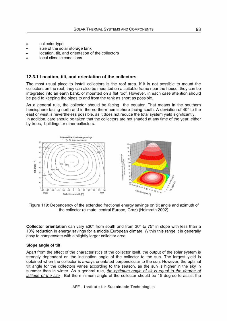
SOLAR THERMAL SYSTEMS AND COMPONENTS
AEE - Institute for Sustainable Technologies
93
• collector type • size of the solar storage tank • location, tilt, and orientation of the collectors • local climatic conditions 12.3.1 Location, tilt, and orientation of the collectors The most usual place to install collectors is the roof area. If it is not possible to mount the collectors on the roof, they can also be mounted on a suitable frame near the house, they can be integrated into an earth bank, or mounted on a flat roof. However, in each case attention should be paid to keeping the pipes to and from the tank as short as possible. As a general rule, the collector should be facing the equator. That means in the southern hemisphere facing north and in the northern hemisphere facing south. A deviation of 40° to the east or west is nevertheless possible, as it does not reduce the total system yield significantly. In addition, care should be taken that the collectors are not shaded at any time of the year, either by trees, buildings or other collectors.
Figure 119: Dependency of the extended fractional energy savings on tilt angle and azimuth of
the collector (climate: central Europe, Graz) (Heimrath 2002)
Collector orientation can vary ±30° from south and from 30° to 75° in slope with less than a 10% reduction in energy savings for a middle European climate. Within this range it is generally easy to compensate with a slightly larger collector area. Slope angle of tilt Apart from the effect of the characteristics of the collector itself, the output of the solar system is strongly dependent on the inclination angle of the collector to the sun. The largest yield is obtained when the collector is always orientated perpendicular to the sun. However, the optimal tilt angle for the collectors varies according to the season, as the sun is higher in the sky in summer than in winter. As a general rule, the optimum angle of tilt is equal to the degree of latitude of the site . But the minimum angle of the collector should be 15 degree to assist the

SOLAR THERMAL SYSTEMS AND COMPONENTS
AEE - Institute for Sustainable Technologies
94
thermosyphon effect. The following table shows optimum tilt angles of different latitudes and seasons. Table 11: Tilt angle for different latitudes and seasons
Latitude [degree]
Best collector tilt in:
June Orientation Sept./March
Orientation December Orientation
50 N 26.5 S 50 S 73.5 S 40 N 16.5 S 40 S 63.5 S 30 N 6.5 S 30 S 53.5 S 20 N 3.5 N 20 S 43.5 S 15 N 8.5 N 15 S 38.5 S 10 N 13.5 N 10 S 33.5 S
Equator = 0 23.5 N 0 - 23.5 S 10 S 33.5 N 10 N 13.5 S 15 S 38.5 N 15 N 8.5 S 20 S 43.5 N 20 N 3.5 S 30 S 53.5 N 30 N 6.5 N 40 S 63.5 N 40 N 16.5 N 50 S 73.5 N 50 N 26.5 N
Optimum tilt angle – Example 1: Vienna, Austria Location: Vienna, Austria Latitude: 48 degree north (see table: latitude = 50 degree) For a south-orientated surface, the optimum tilt angle in December is 73.5°. In June, the most favourable angle would be 26.5°. An angle of 45 - 50° is ideal for use throughout the year. Optimum tilt angle – Example 2: Johannesburg, South Africa Location: Johannesburg, South Africa Latitude: 26.12 degree South (see table: latitude = 30 degree) For a north-orientated surface, the energy gain in June is largest for a tilt angle of 53.5°. In December, the most favourable angle would be 6.5° north facing. An angle of 26° is ideal for use throughout the year. Note: To ensure a good performance of a thermosyphon system a minimum tilt angle of 15° is recommended.

SOLAR THERMAL SYSTEMS AND COMPONENTS
AEE - Institute for Sustainable Technologies
95
12.3.2 Dimensioning guidelines The dimensioning indicated in the tables below is to be understood as guidelines for central European (Table 12) and Central American (Table 13) conditions. In order to gain exact information, a calculation based on the system site characteristics in question is recommended. Such calculations can be performed with the help of simulation programs. These give exact predictions of the solar fraction and the system efficiency for the planned system as well as information on the additional energy needed during the rainy season. Table 12. Dimensioning of domestic hot water solar systems for central European conditions
Daily hot water demand [litres]
Solar storage capacity [litres] Collector area* SC [m2]
100 200 4 200 400 6 300 500 – 750 8 - 12 500 750 - 1000 12 - 16
Table 13: Dimensioning of domestic hot water solar systems for southern African conditions
Daily hot water demand [litres]
Solar storage capacity [litres]
Collector area* SV [m2] Collector area* SC [m2]
50 50 – 75 1.0 – 1.5 0.9 – 1.3 100 100 – 150 2.0 – 3.0 1.5 – 2.5 200 200 – 300 3.5 – 4.5 3.0 – 4.0 300 300 – 450 4.5 – 6.0 4.0 – 5.0 500 500 - 750 7.5 - 10 6.0 – 8.5
*) depending on the required solar fraction SV ... coating of solar varnish SC ... selective coating
13 DIMENSIONING - SOLAR COMBISYSTEMS Solar combisystems differ from purely solar domestic hot water systems in several key aspects, which means that the dimensioning of them differs in several ways. The main difference is the extra space-heating load, resulting in a total heat demand that varies considerably during the year, and the fact that the thermal energy is not usually stored as hot water used for showers etc. Consequently, solar combisystems tend to be more complex and larger than solar domestic hot water systems, and they have excess capacity during the summer.
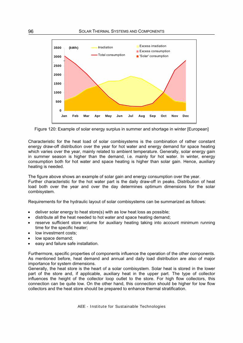
SOLAR THERMAL SYSTEMS AND COMPONENTS
AEE - Institute for Sustainable Technologies
96
Figure 120: Example of solar energy surplus in summer and shortage in winter [European]
Characteristic for the heat load of solar combisystems is the combination of rather constant energy draw-off distribution over the year for hot water and energy demand for space heating which varies over the year, mainly related to ambient temperature. Generally, solar energy gain in summer season is higher than the demand, i.e. mainly for hot water. In winter, energy consumption both for hot water and space heating is higher than solar gain. Hence, auxiliary heating is needed. The figure above shows an example of solar gain and energy consumption over the year. Further characteristic for the hot water part is the daily draw-off in peaks. Distribution of heat load both over the year and over the day determines optimum dimensions for the solar combisystem. Requirements for the hydraulic layout of solar combisystems can be summarized as follows: • deliver solar energy to heat store(s) with as low heat loss as possible; • distribute all the heat needed to hot water and space heating demand; • reserve sufficient store volume for auxiliary heating taking into account minimum running
time for the specific heater; • low investment costs; • low space demand; • easy and failure safe installation. Furthermore, specific properties of components influence the operation of the other components. As mentioned before, heat demand and annual and daily load distribution are also of major importance for system dimensions. Generally, the heat store is the heart of a solar combisystem. Solar heat is stored in the lower part of the store and, if applicable, auxiliary heat in the upper part. The type of collector influences the height of the collector loop outlet to the store. For high flow collectors, this connection can be quite low. On the other hand, this connection should be higher for low flow collectors and the heat store should be prepared to enhance thermal stratification.
0
500
1000
1500
2000
2500
3000
3500
Jan Feb Mar Apr May Jun Jul Aug Sep Oct Nov Dec
(kWh) Excess irradiationExcess consumption'Solar' consumption
Irradiation
Total consumption

SOLAR THERMAL SYSTEMS AND COMPONENTS
AEE - Institute for Sustainable Technologies
97
For combisystems with indirect integrated auxiliary heating, the inlet pipe from the heater is connected at the top. The height of the outlet depends on the peak hot water demand, the outlet pipes to the heat distribution system and the volume needed for solar energy. The distance Minimum operation time for the heater also determines the auxiliary volume. Requirements are stricter for wood burners than for gas. Another influence is the type of heat distribution system, e.g. connection from high temperature radiators to the store should be higher than from a low temperature heat distribution system. This indicates that system design largely depends on national building traditions, auxiliary energy source and user behavior.
Kollek t o r
f e l d
Wärme- erzeuger
R a u m h e iz u n g
Figure 121: Hydraulic scheme of a solar combisystem (single storage system)
Since the dimensioning of a solar combisystem depends on several conditions, in the following a dimensioning nomogram is shown, which is based on the following hydraulic scheme and the data presented in the table below. It is also based on Austrian climatic conditions:
Kollek
torfel
d Wärme-erzeuger
Raumheizung
Figure 122: Hydraulic scheme of a solar combisystem (two storage system)
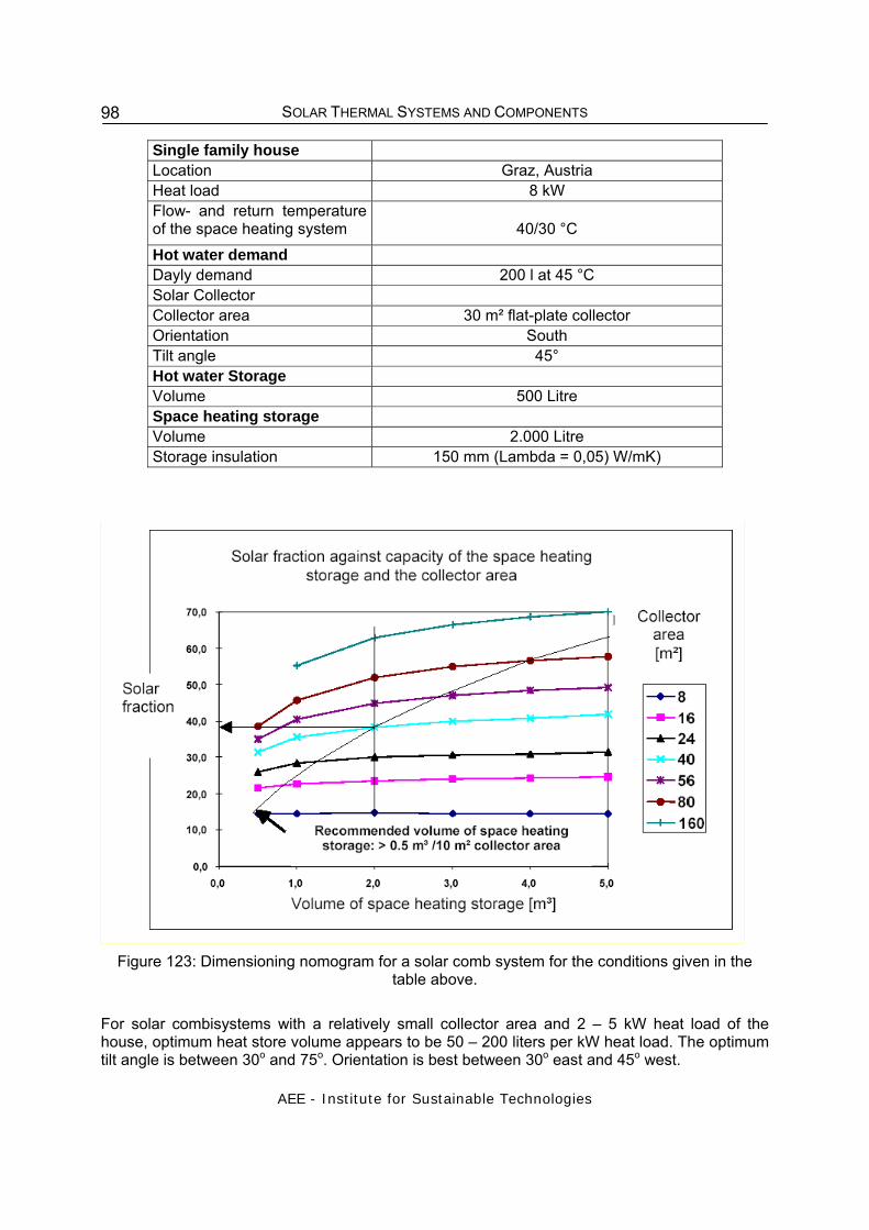
SOLAR THERMAL SYSTEMS AND COMPONENTS
AEE - Institute for Sustainable Technologies
98
Single family house Location Graz, Austria Heat load 8 kW Flow- and return temperature of the space heating system
40/30 °C
Hot water demand Dayly demand 200 l at 45 °C Solar Collector Collector area 30 m² flat-plate collector Orientation South Tilt angle 45° Hot water Storage Volume 500 Litre Space heating storage Volume 2.000 Litre Storage insulation 150 mm (Lambda = 0,05) W/mK)
Figure 123: Dimensioning nomogram for a solar comb system for the conditions given in the
table above.
For solar combisystems with a relatively small collector area and 2 – 5 kW heat load of the house, optimum heat store volume appears to be 50 – 200 liters per kW heat load. The optimum tilt angle is between 30o and 75o. Orientation is best between 30o east and 45o west.

SOLAR THERMAL SYSTEMS AND COMPONENTS
AEE - Institute for Sustainable Technologies
99
Simulation programs There are several computer programs on the market for the thermal performance calculation of solar combisystems: Polysun, TSOL and SHWwin. All are transient simulation programs with time steps of a few minutes and feature database support for components and systems. Heat loads can also be defined in great detail. Possible system layouts are, however, restricted and differ from one program to the other. A more general computer program is TRNSYS., Solar combi systems can be composed from TRNSYS modules. Further information on solar combi systems: Weiss, W. (Ed.): Solar Heating Systems for Houses. A design handbook for solar combisystems, James & James, London 2003
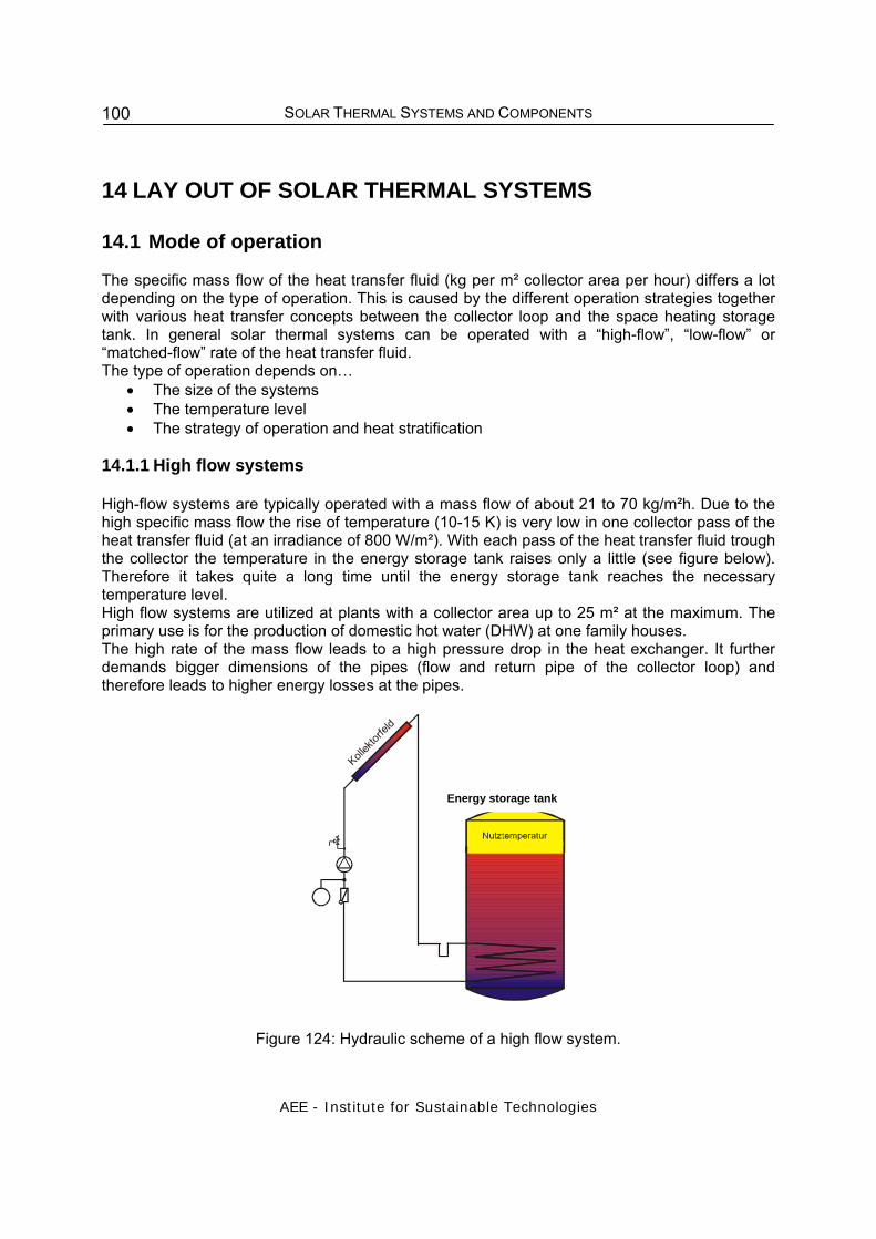
SOLAR THERMAL SYSTEMS AND COMPONENTS
AEE - Institute for Sustainable Technologies
100
14 LAY OUT OF SOLAR THERMAL SYSTEMS
14.1 Mode of operation The specific mass flow of the heat transfer fluid (kg per m² collector area per hour) differs a lot depending on the type of operation. This is caused by the different operation strategies together with various heat transfer concepts between the collector loop and the space heating storage tank. In general solar thermal systems can be operated with a “high-flow”, “low-flow” or “matched-flow” rate of the heat transfer fluid. The type of operation depends on…
• The size of the systems • The temperature level • The strategy of operation and heat stratification
14.1.1 High flow systems
High-flow systems are typically operated with a mass flow of about 21 to 70 kg/m²h. Due to the high specific mass flow the rise of temperature (10-15 K) is very low in one collector pass of the heat transfer fluid (at an irradiance of 800 W/m²). With each pass of the heat transfer fluid trough the collector the temperature in the energy storage tank raises only a little (see figure below). Therefore it takes quite a long time until the energy storage tank reaches the necessary temperature level. High flow systems are utilized at plants with a collector area up to 25 m² at the maximum. The primary use is for the production of domestic hot water (DHW) at one family houses. The high rate of the mass flow leads to a high pressure drop in the heat exchanger. It further demands bigger dimensions of the pipes (flow and return pipe of the collector loop) and therefore leads to higher energy losses at the pipes.
Kollek
torfel
d
Figure 124: Hydraulic scheme of a high flow system.
Energy storage tank

SOLAR THERMAL SYSTEMS AND COMPONENTS
AEE - Institute for Sustainable Technologies
101
14.1.2 Low-flow systems
Large solar thermal systems (more than 10 to 15 m²) should be operated according to the “low-flow principle”. This means a specific mass flow in the collector of 5-20 kg/m²h. Due to this low mass flow - compared to high-flow systems - the rise of temperature (delta T) in one collector pass is much higher. A temperature level of e.g. 65°C can be reached in one collector pass already. The perfectly vertical energy storage tank must be loaded in a stratified manner in order to be able to provide this high temperature level immediately to the user (see figures below). Stratified energy storage tanks are necessary for efficient low-flow systems.
Kollek
torfel
d
Figure 125: Hydraulic scheme of a low flow system with stratified charging of the energy storage
tank.
Insulation of the lid Insulation of casing Tank Solar flow pipe Space heating flow pipe Stratifier with membrane flaps Space heating return pipe Hot water flow pipe Solar return pipe (with baffle plate Insulation bottom
Figure 126: Stratified charging of the storage tank (Source: SOLVIS)
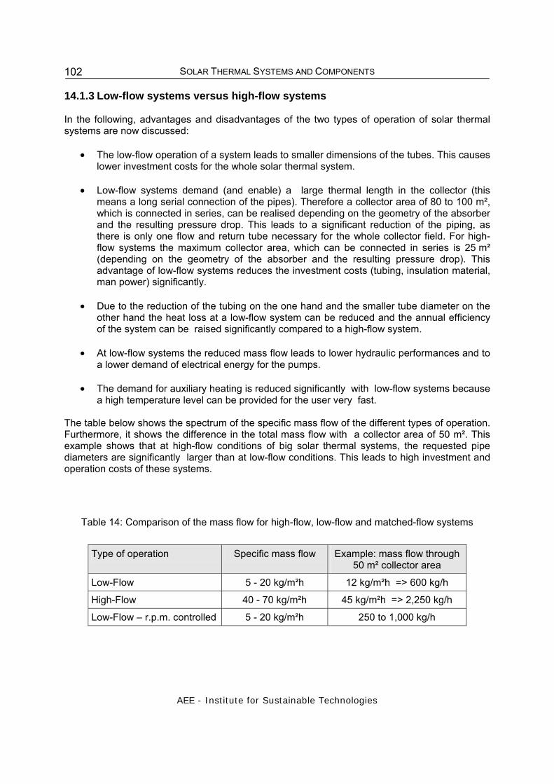
SOLAR THERMAL SYSTEMS AND COMPONENTS
AEE - Institute for Sustainable Technologies
102
14.1.3 Low-flow systems versus high-flow systems In the following, advantages and disadvantages of the two types of operation of solar thermal systems are now discussed:
• The low-flow operation of a system leads to smaller dimensions of the tubes. This causes lower investment costs for the whole solar thermal system.
• Low-flow systems demand (and enable) a large thermal length in the collector (this
means a long serial connection of the pipes). Therefore a collector area of 80 to 100 m², which is connected in series, can be realised depending on the geometry of the absorber and the resulting pressure drop. This leads to a significant reduction of the piping, as there is only one flow and return tube necessary for the whole collector field. For high-flow systems the maximum collector area, which can be connected in series is 25 m² (depending on the geometry of the absorber and the resulting pressure drop). This advantage of low-flow systems reduces the investment costs (tubing, insulation material, man power) significantly.
• Due to the reduction of the tubing on the one hand and the smaller tube diameter on the
other hand the heat loss at a low-flow system can be reduced and the annual efficiency of the system can be raised significantly compared to a high-flow system.
• At low-flow systems the reduced mass flow leads to lower hydraulic performances and to
a lower demand of electrical energy for the pumps.
• The demand for auxiliary heating is reduced significantly with low-flow systems because a high temperature level can be provided for the user very fast.
The table below shows the spectrum of the specific mass flow of the different types of operation. Furthermore, it shows the difference in the total mass flow with a collector area of 50 m². This example shows that at high-flow conditions of big solar thermal systems, the requested pipe diameters are significantly larger than at low-flow conditions. This leads to high investment and operation costs of these systems.
Table 14: Comparison of the mass flow for high-flow, low-flow and matched-flow systems
Type of operation Specific mass flow Example: mass flow through
50 m² collector area
Low-Flow 5 - 20 kg/m²h 12 kg/m²h => 600 kg/h
High-Flow 40 - 70 kg/m²h 45 kg/m²h => 2,250 kg/h
Low-Flow – r.p.m. controlled 5 - 20 kg/m²h 250 to 1,000 kg/h

SOLAR THERMAL SYSTEMS AND COMPONENTS
AEE - Institute for Sustainable Technologies
103
The following equation shows the calculation of the mass flow for the primary circuit of the solar thermal system:
specificcollectorprimary mAm && ⋅= [kg/h]
primarym& mass flow of the primary circuit of the solar thermal system [kg/h] collectorA collector area (aperture area) [m²]
specificm& specific mass flow for the primary circuit of the solar thermal system [kg/m²h] Comparison of a typical low-flow and high-flow system by the means of:
• Collector hydraulics • Efficiency of the collector • Pressure drop of the collector and the system • Hydraulic efficiency and electrical pump efficiency
The boundary conditions for the comparison are:
• Gross collector area: 40 m² (10 m x 4 m) • Collector values: c0=0.77, c1=3.33 W/m²K, c2=0.012 W/m²K² • Inner diameter of the absorber pipe: 8.25 mm • Ambient temperature: 20 °C • Irradiation on the collector area: 800 W/m² • Average collector temperature: 46.5°C (for both systems)
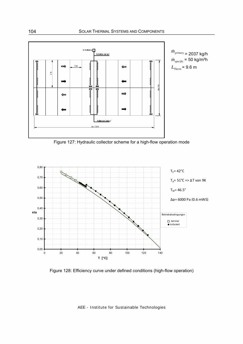
SOLAR THERMAL SYSTEMS AND COMPONENTS
AEE - Institute for Sustainable Technologies
104
Figure 127: Hydraulic collector scheme for a high-flow operation mode
0,00
0,10
0,20
0,30
0,40
0,50
0,60
0,70
0,80
0 20 40 60 80 100 120 140
T [°C]
etaBetriebsbedingungen
laminar turbulent
Figure 128: Efficiency curve under defined conditions (high-flow operation)
primarym& = 2037 kg/h specificm& = 50 kg/m²h
ThermL = 9.6 m
TE= 42°C
TA= 51°C => ΔT von 9K
TM= 46.5°
Δp= 6000 Pa (0.6 mWS)

SOLAR THERMAL SYSTEMS AND COMPONENTS
AEE - Institute for Sustainable Technologies
105
ca. 10 m
Kollektorrücklauf
Kollektorvorlauf
2 m
Entlüftung
1 m
ca. 4
m
Figure 129: Hydraulic collector scheme for a low-flow operation mode
0,00
0,10
0,20
0,30
0,40
0,50
0,60
0,70
0,80
0 20 40 60 80 100 120 140
T [°C]
etaBetriebsbedingungen
laminar turbulent
Figure 130: Efficiency curve under defined conditions (low-flow operation)
primarym&= 555 kg/h
specificm& = 14 kg/m²h
ThermL = 38.4 m
TE= 30°C
TA= 63°C => ΔT von 33K TM= 46.5°C
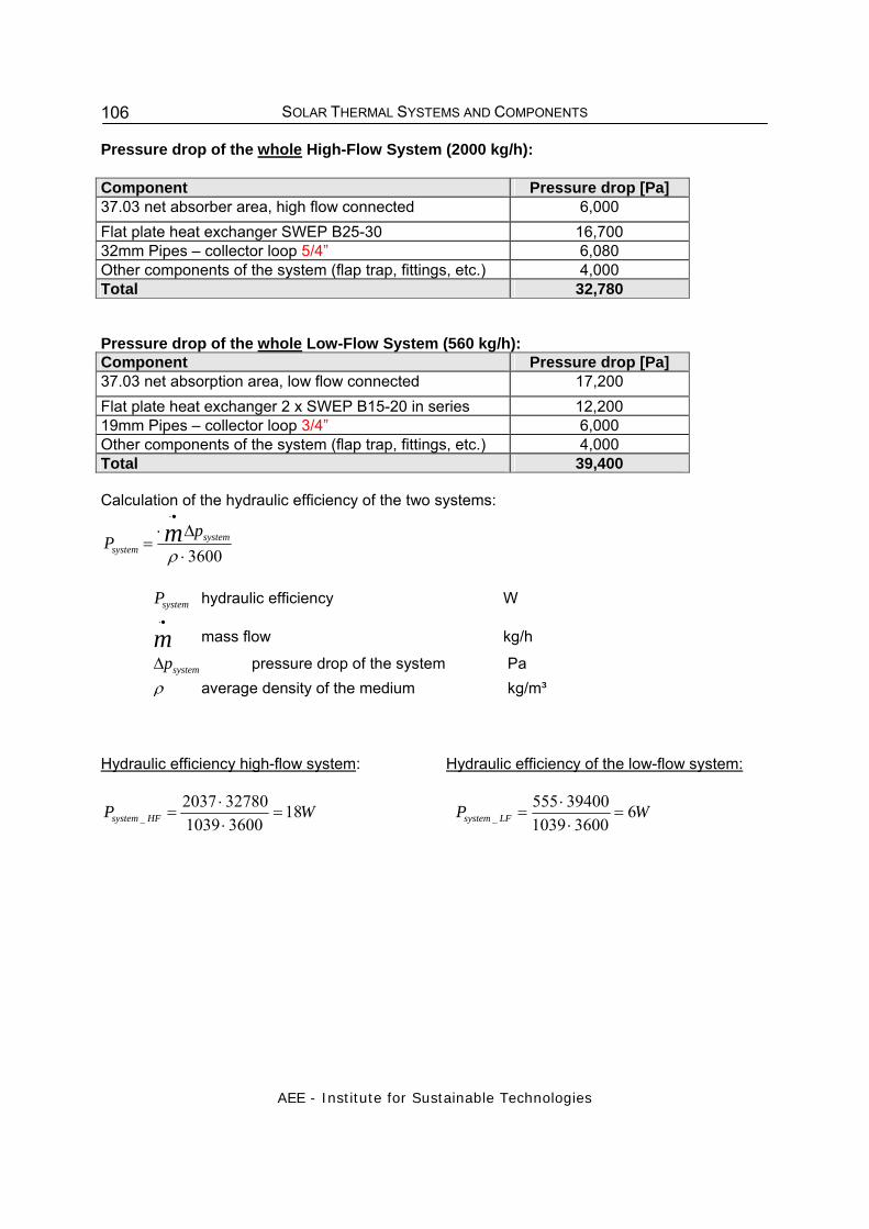
SOLAR THERMAL SYSTEMS AND COMPONENTS
AEE - Institute for Sustainable Technologies
106
Pressure drop of the whole High-Flow System (2000 kg/h): Component Pressure drop [Pa] 37.03 net absorber area, high flow connected 6,000 Flat plate heat exchanger SWEP B25-30 16,700 32mm Pipes – collector loop 5/4” 6,080 Other components of the system (flap trap, fittings, etc.) 4,000 Total 32,780 Pressure drop of the whole Low-Flow System (560 kg/h): Component Pressure drop [Pa] 37.03 net absorption area, low flow connected 17,200 Flat plate heat exchanger 2 x SWEP B15-20 in series 12,200 19mm Pipes – collector loop 3/4” 6,000 Other components of the system (flap trap, fittings, etc.) 4,000 Total 39,400 Calculation of the hydraulic efficiency of the two systems:
3600⋅Δ⋅
=
•⋅
ρsystem
system
pP m
systemP hydraulic efficiency W
m•⋅
mass flow kg/h
systempΔ pressure drop of the system Pa ρ average density of the medium kg/m³
Hydraulic efficiency high-flow system: Hydraulic efficiency of the low-flow system:
WP HFsystem 1836001039327802037
_ =⋅⋅
= WP LFsystem 636001039
39400555_ =
⋅⋅
=

SOLAR THERMAL SYSTEMS AND COMPONENTS
AEE - Institute for Sustainable Technologies
107
Low-flow system: UPS 25-50, Level 3
High-flow system: UPS 25-60, Level 3
Figure 131: Choice of pump
Conclusion: => pump efficiencies <20% => Required power of the pump of the low-flow system is about 15% lower than for high-flow system
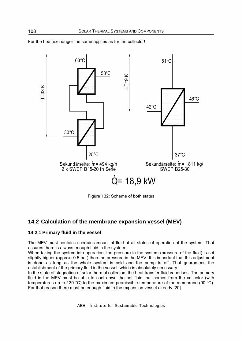
SOLAR THERMAL SYSTEMS AND COMPONENTS
AEE - Institute for Sustainable Technologies
108
For the heat exchanger the same applies as for the collector!
Q= 18,9 kW
Sekundärseite: m= 494 kg/h2 x SWEP B15-20 in Serie
63°C
T=33
K
30°CT=
9 K
25°C
58°C
Sekundärseite: m= 1811 kg/SWEP B25-30
42°C
37°C
46°C
51°C
Figure 132: Scheme of both states
14.2 Calculation of the membrane expansion vessel (MEV) 14.2.1 Primary fluid in the vessel The MEV must contain a certain amount of fluid at all states of operation of the system. That assures there is always enough fluid in the system. When taking the system into operation, the pressure in the system (pressure of the fluid) is set slightly higher (approx. 0.5 bar) than the pressure in the MEV. It is important that this adjustment is done as long as the whole system is cold and the pump is off. That guarantees the establishment of the primary fluid in the vessel, which is absolutely necessary. In the state of stagnation of solar thermal collectors the heat transfer fluid vaporises. The primary fluid in the MEV must be able to cool down the hot fluid that comes from the collector (with temperatures up to 130 °C) to the maximum permissible temperature of the membrane (90 °C). For that reason there must be enough fluid in the expansion vessel already [20].

SOLAR THERMAL SYSTEMS AND COMPONENTS
AEE - Institute for Sustainable Technologies
109
14.2.2 Primary pressure in the MEV In order to push back the expanded volume into the system and to make sure not too much fluid enters the expansion vessel a primary pressure is necessary. If there is too little pressure, a lot of heat transfer fluid enters the expansion vessel at low system temperatures. The consequences would be that at higher temperatures no more fluid could enter the expansion vessel. With closed systems the content of the collector vaporises at stagnation and the expansion vessel must be able to take in the whole volume of the collector. Other wise the pressure of the system would exceed the pressure that is necessary to release the safety valve, which would lead to a loss of fluid. It is very important to check the primary pressure when installing the expansion vessel. It is further recommended to have periodical checks every one or two years.
14.2.3 Permeability Inside the MEV the entrance of gas in the water is almost impossible. This is caused by the low permeability of the installed membrane. The use of expansion vessels that are open to the atmosphere is not recommended. 14.2.4 Design of the solar membrane expansion vessel
In general it must be said that it is better to choose the expansion vessel rather too big than too small! The results of simulations of expansion vessels are often too optimistic. Certain processes in the solar thermal system like the stagnation have not (or not adequately) been taken into account. Please see in the following calculation method that considers the influence of the stagnation to the state of the art.
N 0,5<=
120°C
50°C
an der Membran:90°C
max. Temperatur
stat
isch
e A
nlag
enhö
h e [b
ar]
Kollek
tor
Figure 133: Actual use of the
MEV (20)
Figure 134: Primary fluid in the MEV (21)
Figure 135: Minimal primary pressure in the MEV (20)
The following important parameters must be well-known for simulation and installation: The efficiency is given by the manufacturer. It specifies the volume of the expansion vessel that can actually be used without expanding the membrane excessively. This would lead to damage on the membrane and to a lower life time of the expansion vessel. Usually the efficiency is less than 0.5 .

SOLAR THERMAL SYSTEMS AND COMPONENTS
AEE - Institute for Sustainable Technologies
110
The primary pressure in the expansion vessel should at least correspond to the static hydraulic head of the system. Because of the primary pressure, the pressure in the system is also high enough in the upper parts of the system. It also prevents air from coming into the system when the heat transfer fluid cools down. After aerating the systems several times there must be enough fluid left. The primary fluid in the expansion vessel takes care of this. Additionally, the primary fluid must protect the membrane against high temperatures at stagnation. The nominal volume VN of the expansion vessel (see equation) is calculated in the well known way from the heat expansion of the total content of the heat exchanging fluid VG*n, the primary fluid VV, the volume of the vapour VD and the efficiency N. Compared to previous calculations a bigger volume of the vapour has to be taken into account. Corresponding to the given details above the volume of all pipes and components reached by the vapour has to be calculated. Up to now the efficiency has only been calculated from the pressure of the system Pe and the primary pressure of the expansion vessel P0. In the new method of calculation the difference of height Hdiff between the expansion vessel and the safety valve is considered (equation 4). These components may be installed in different storeys of the building and lead to the pressure difference Pdiff. The rise of temperature of the gas filling during operation is also considered (differences of 30 K have been measured). This leads to the quotient 0.9. These changes result from the application of the general gas law to the conditions at issue:
NVVnV
V DVGN
++⋅>
(equation 1)
99.01 ≈−=hot
coldnρρ
(equation 2)
10000081,9⋅⋅−
= colddiffdiff
HP
ρ (equation 3)
000,10081.9⋅⋅−
= colddiffdiff
HP
ρ (equation 4)
Hereby means:
VN nominal volume of the expansion vessel litre
VG total volume of the heat exchanging fluid litre
VV primary fluid litre
VD maximum volume of the vapour litre
n coefficient of expansion (~ 0.09 for expansion at ~120 °C for 40 % propylene glycol)
N efficiency of the expansion vessel, according to manufacturer ≤ 0,5
ρ density of heat transfer fluid kg/m³
Pe pressure of system at safety valve = nominal pressure safety valve – 20 % bar
0.09)

SOLAR THERMAL SYSTEMS AND COMPONENTS
AEE - Institute for Sustainable Technologies
111
P0 primary pressure, bar. The factor 0.9 in (P0+1)/0.9 stands for a change of temperature in the gas containing space because of the hot fluid
Hdiff difference of height between the expansion vessel and the Safety valve
Hdiff = height of expansion vessel – height of safety valve m
Pdiff difference of pressure according to Hdiff bar
As mentioned above, the primary fluid in the expansion vessel must be able to cool down the hot heat exchange fluid coming from the collector. The maximum permissible temperature in the expansion vessel according to the manufacturer is 90 °C. The dimensioning of the minimum of primary fluid in the expansion vessel VV is shown in equation 6: maximum permissible temperature in expansion vessel Tmax = 90 °C, average temperature in the primary circuit 90 °C, origin temperature of the primary fluid TV = 50 °C (according to measurements), In the worst case the expansion vessel must be able to take in the whole volume of the collector VK at a temperature of TK = 130 °C.
Vmax
maxKKV TT
TTVV
−−
⋅≥ (equation 5)
VV primary fluid litre VK volume inside the collector litre TK temperature of the fluid at entering the expansion vessel °C Tmax maximum permissible temperature in expansion vessel °C From this assumption it follows that the volume of the primary fluid must be equivalent to the volume of the collector. Example of calculation: Starting conditions: Single family house Collector area: 10 m² (collector that empties well) Flow pipe VL: 15 m Cu pipe 18x1 Return pipe VL: 15 m Cu pipe 18x1 Safety valve: 6 bar Pressure of the system: 2.5 bar Primary pressure in the expansion vessel: 2.0 bar We are looking for the volume of the expansion vessel [litre] A) Formula for calculation
NVVnVV DVG
N++⋅
>

SOLAR THERMAL SYSTEMS AND COMPONENTS
AEE - Institute for Sustainable Technologies
112
MEV nominal volume VN litre VD maximum vapour volume litre VG total volume of the heat transfer fluid litre VV primary fluid litre n coefficient of expansion of the heat transfer fluid B) Calculation of the MEV efficiency:
19,0
)1(1 0
++
+−++
=diffe
diffe
PP
PPP
N
N MEV efficiency Pe nominal pressure of safety valve bar P0 primary pressure bar
000,10081.9⋅⋅−
= colddiffdiff
HP
ρ
Pdiff pressure difference bar Hdiff HMEV–HSV m r density of the heat transfer fluid kg/m³ ~1051 kg/m³
barPdiff 052.0000,100
81.910515.0=
⋅⋅=
Pe = nominal pressure of safety valve – tolerance of respond (20 %) Pe = 6 bar – 20 % = 4.8 bar Pressure difference Pdiff = 0.052 bar Nominal pressure of safety valve Pe = 4.8 bar Po = 2.0 bar
43.01052.08.4
9.0)10.2(1052.08.4
19.0
)1(1 0
=++
+−++
=++
+−++
=diffe
diffe
PP
PPPN
C) Calculation of the volume of the heat transfer fluid: VG = Vpipe+ Vcoll + Vheat exchanger litre Factor of expansion n

SOLAR THERMAL SYSTEMS AND COMPONENTS
AEE - Institute for Sustainable Technologies
113
99.01 ≈−=hot
coldnρρ
5.120.25.43004
16.0 2
=++⋅⋅
=π
GV litre
Calculation of the primary fluid VV: The volume of the primary fluid is more or less equivalent to the volume of the collector. ->VV = Vcoll = 4.5 litre D) Calculation of the volume of vapour VD: VD = Vcoll + Vpipe-vapor litre Vcoll = 4.5 litre Calculation of the volume of vapour in the pipes Maximum vapor power= 10 m² * 50 W/m² = 500 W Calculation of the reach of the vapour in the solar pipes Vpipe-vapor (calculation through the thermal power loss of the pipes): thermal power loss of the pipe: 25 W/m (reach of vapour in the pipe) = (max. vapour power)/( thermal power loss of the pipe per meter of pipe) (reach of vapour in the pipe) = 500/25 = 20 meter 16er Cu pipe VD = 4.5 + 4.0 = 8.5 litre
0,42004
16,0 2
=⋅⋅
=−π
vapourpipeV litre
E) Calculation of the volume of the expansion vessel:
litreN
VVnVV DVG
N 8,3243,0
5,85,409,05.12=
++⋅=
++⋅>
Selection of the expansion vessel -> 35 litre
14.2.5 Installation In principle the expansion vessel should be installed in a hanging way. The standing mounting leads to the following effect: If hot water streams by the expansion vessel it also enters the expansion vessel, because the density of hot water is lower than the density of the cold water inside the vessel
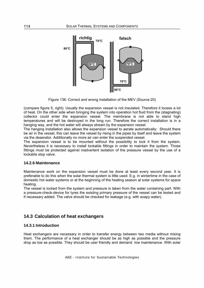
SOLAR THERMAL SYSTEMS AND COMPONENTS
AEE - Institute for Sustainable Technologies
114
Figure 136: Correct and wrong installation of the MEV (Source:20) (compare figure 5, right). Usually the expansion vessel is not insulated. Therefore it looses a lot of heat. On the other side when bringing the system into operation hot fluid from the (stagnating) collector could enter the expansion vessel. The membrane is not able to stand high temperatures and will be destroyed in the long run. Therefore the correct installation is in a hanging way, and the hot water will always stream by the expansion vessel. The hanging installation also allows the expansion vessel to aerate automatically: Should there be air in the vessel, this can leave the vessel by rising in the pipes by itself and leave the system via the deaerator. Additionally no more air can enter the suspended vessel. The expansion vessel is to be mounted without the possibility to lock it from the system. Nevertheless it is necessary to install lockable fittings in order to maintain the system. Those fittings must be protected against inadvertent isolation of the pressure vessel by the use of a lockable stop valve.
14.2.6 Maintenance Maintenance work on the expansion vessel must be done at least every second year. It is preferable to do this when the solar thermal system is little used. E.g. in wintertime in the case of domestic hot water systems or at the beginning of the heating season at solar systems for space heating. The vessel is locked from the system and pressure is taken from the water containing part. With a pressure-check-device for tyres the existing primary pressure of the vessel can be tested and if necessary added. The valve should be checked for leakage (e.g. with soapy water).
14.3 Calculation of heat exchangers 14.3.1 Introduction Heat exchangers are necessary in order to transfer energy between two media without mixing them. The performance of a heat exchanger should be as high as possible and the pressure drop as low as possible. They should be user friendly and demand low maintenance. With solar

SOLAR THERMAL SYSTEMS AND COMPONENTS
AEE - Institute for Sustainable Technologies
115
thermal systems the heat exchanger is a very important component. The exchanging temperature has a very high impact on the operation of the collectors. In the primary circuit heat is generated in the collectors and a heat transfer fluid (mixture of water an anti freeze) is circulating. In the secondary circuit water is circulating (drinking water or water for space heating). The heat from the primary circuit should be transferred to the secondary circuit. using a very low temperature difference. The temperature difference of a heat exchanger describes the difference between the temperature at the entrance of the one circuit and the exit of the other circuit. The lower the temperature difference, the larger the area of the heat exchanger required . Usually the temperature difference is about 5K. Lower temperature differences are not economically Viable. The distance covered by the media to transfer the heat (e.g. in a pipe) is called the thermal length. A very low temperature loss is aspired. According to the type of heat exchanger the circulation in the secondary circuit takes place: free convection because of gravity in internal heat exchangers (finned tube heat exchanger, smooth tube heat exchanger) and forced convection in external heat exchangers (plate heat exchanger, coil heat exchanger). In the following, plate heat exchangers and internal heat exchangers are described in detail, as they are most frequently used.
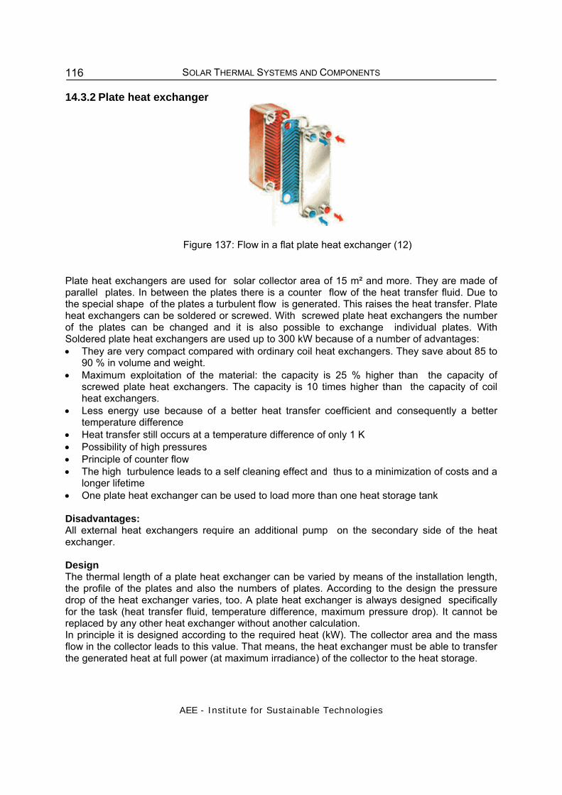
SOLAR THERMAL SYSTEMS AND COMPONENTS
AEE - Institute for Sustainable Technologies
116
14.3.2 Plate heat exchanger
Figure 137: Flow in a flat plate heat exchanger (12)
Plate heat exchangers are used for solar collector area of 15 m² and more. They are made of parallel plates. In between the plates there is a counter flow of the heat transfer fluid. Due to the special shape of the plates a turbulent flow is generated. This raises the heat transfer. Plate heat exchangers can be soldered or screwed. With screwed plate heat exchangers the number of the plates can be changed and it is also possible to exchange individual plates. With Soldered plate heat exchangers are used up to 300 kW because of a number of advantages: • They are very compact compared with ordinary coil heat exchangers. They save about 85 to
90 % in volume and weight. • Maximum exploitation of the material: the capacity is 25 % higher than the capacity of
screwed plate heat exchangers. The capacity is 10 times higher than the capacity of coil heat exchangers.
• Less energy use because of a better heat transfer coefficient and consequently a better temperature difference
• Heat transfer still occurs at a temperature difference of only 1 K • Possibility of high pressures • Principle of counter flow • The high turbulence leads to a self cleaning effect and thus to a minimization of costs and a
longer lifetime • One plate heat exchanger can be used to load more than one heat storage tank Disadvantages: All external heat exchangers require an additional pump on the secondary side of the heat exchanger. Design The thermal length of a plate heat exchanger can be varied by means of the installation length, the profile of the plates and also the numbers of plates. According to the design the pressure drop of the heat exchanger varies, too. A plate heat exchanger is always designed specifically for the task (heat transfer fluid, temperature difference, maximum pressure drop). It cannot be replaced by any other heat exchanger without another calculation. In principle it is designed according to the required heat (kW). The collector area and the mass flow in the collector leads to this value. That means, the heat exchanger must be able to transfer the generated heat at full power (at maximum irradiance) of the collector to the heat storage.
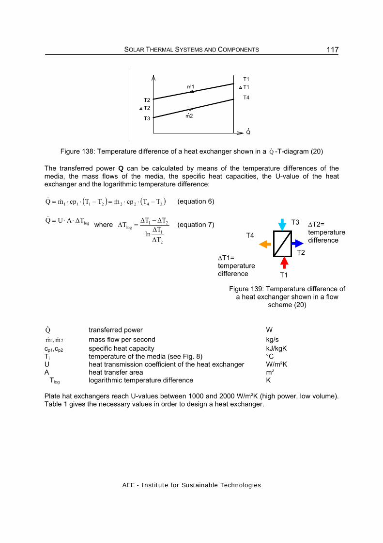
SOLAR THERMAL SYSTEMS AND COMPONENTS
AEE - Institute for Sustainable Technologies
117
T1
T2
T3
T4
Q
T1
T2
m1
m2
Figure 138: Temperature difference of a heat exchanger shown in a Q& -T-diagram (20) The transferred power Q can be calculated by means of the temperature differences of the media, the mass flows of the media, the specific heat capacities, the U-value of the heat exchanger and the logarithmic temperature difference:
( ) ( )34222111 TTcpmTTcpmQ −⋅⋅=−⋅⋅= &&& (equation 6)
logTAUQ Δ⋅⋅=& where
2
1
21log
TTln
TTT
ΔΔ
Δ−Δ=Δ (equation 7)
Q& transferred power W
21 m,m && mass flow per second kg/s cp1,cp2 specific heat capacity kJ/kgK Ti temperature of the media (see Fig. 8) °C U heat transmission coefficient of the heat exchanger W/m²K A heat transfer area m² �Tlog logarithmic temperature difference K Plate hat exchangers reach U-values between 1000 and 2000 W/m²K (high power, low volume). Table 1 gives the necessary values in order to design a heat exchanger.
Figure 139: Temperature difference of a heat exchanger shown in a flow
scheme (20)
T3
T2
T1
T4 ΔT2= temperature difference
ΔT1= temperature difference
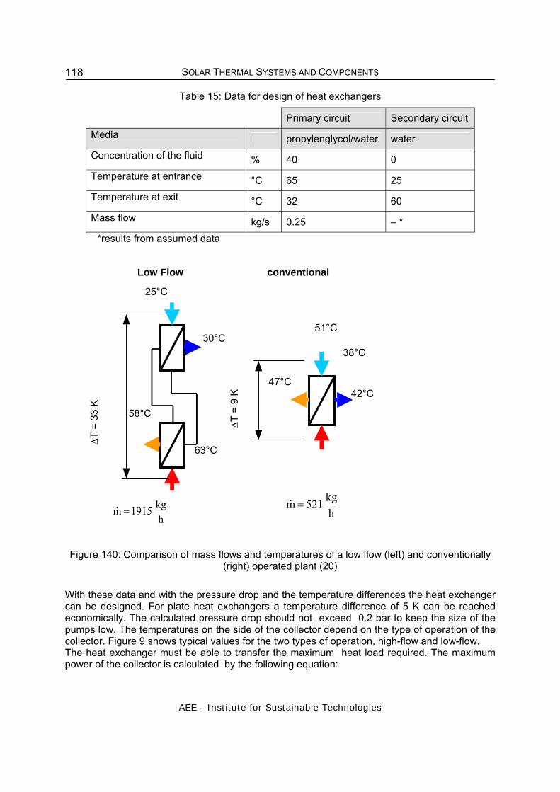
SOLAR THERMAL SYSTEMS AND COMPONENTS
AEE - Institute for Sustainable Technologies
118
Table 15: Data for design of heat exchangers
Primary circuit Secondary circuit Media propylenglycol/water water Concentration of the fluid % 40 0 Temperature at entrance °C 65 25 Temperature at exit °C 32 60 Mass flow kg/s 0.25 – *
*results from assumed data
38°C
ΔT =
9 K
30°C
25°C
ΔT =
33
K
51°C
Low Flow conventional
42°C 47°C
58°C
63°C
hkg 1915 m =& h
kg 521 m =&
Figure 140: Comparison of mass flows and temperatures of a low flow (left) and conventionally (right) operated plant (20)
With these data and with the pressure drop and the temperature differences the heat exchanger can be designed. For plate heat exchangers a temperature difference of 5 K can be reached economically. The calculated pressure drop should not exceed 0.2 bar to keep the size of the pumps low. The temperatures on the side of the collector depend on the type of operation of the collector. Figure 9 shows typical values for the two types of operation, high-flow and low-flow. The heat exchanger must be able to transfer the maximum heat load required. The maximum power of the collector is calculated by the following equation:
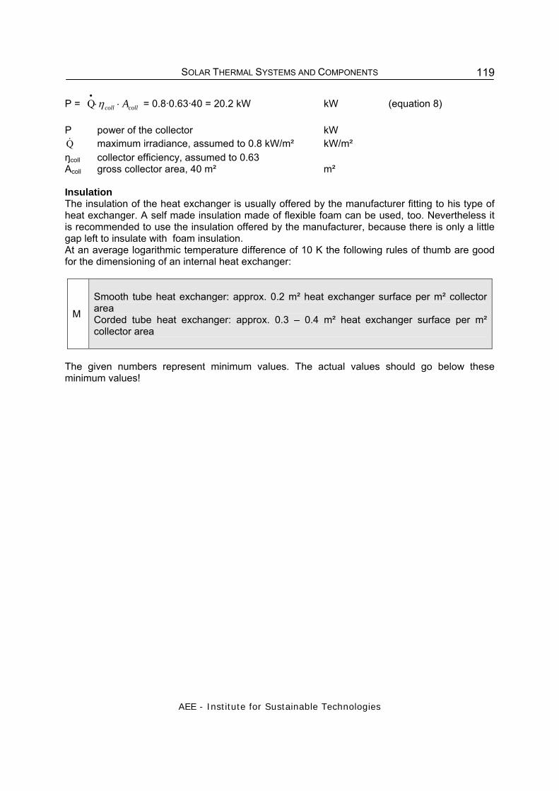
SOLAR THERMAL SYSTEMS AND COMPONENTS
AEE - Institute for Sustainable Technologies
119
P = collcoll A⋅⋅•
ηQ = 0.8·0.63·40 = 20.2 kW kW (equation 8) P power of the collector kW Q& maximum irradiance, assumed to 0.8 kW/m² kW/m² ŋcoll collector efficiency, assumed to 0.63 Acoll gross collector area, 40 m² m² Insulation The insulation of the heat exchanger is usually offered by the manufacturer fitting to his type of heat exchanger. A self made insulation made of flexible foam can be used, too. Nevertheless it is recommended to use the insulation offered by the manufacturer, because there is only a little gap left to insulate with foam insulation. At an average logarithmic temperature difference of 10 K the following rules of thumb are good for the dimensioning of an internal heat exchanger:
M
Smooth tube heat exchanger: approx. 0.2 m² heat exchanger surface per m² collector area Corded tube heat exchanger: approx. 0.3 – 0.4 m² heat exchanger surface per m² collector area
The given numbers represent minimum values. The actual values should go below these minimum values!

SOLAR THERMAL SYSTEMS AND COMPONENTS
AEE - Institute for Sustainable Technologies
120
References: /1/ Duffie J. A., Beckman William A.: Solar Engineering of Thermal Processes, Second Edition, New York, 1991 /2/ Suter J.M., Letz T., Weiss W., Inäbnit J. Solar Combisystems in Austria, Denmark, Germany, Sweden, Switzerland, the Netherlands and the USA, Overview 2000, Bern 2000 Picture Sources
(1) Franz Ketterer Feinmechanik, Sölden bei Freiburg (D) (2) Feingerätebau K.Fischer GmbH, Drebach (D) (3) SolarCosa, Berlin (D) (4) Hessisches Landesamt für Umwelt und Geologie (D) (5) Fachhochschule Mannheim, Institut für naturwissenschaftliche Grundlagen (D) (6) Consolar GmbH, Frankfurt/Main (D) (7) Streicher, W.: Sonnenenergienutzung, Graz, 2003 (A) (8) Volker Quaschning (D), Consolar GmbH, Frankfurt/Main (D) (9) Solution Solartechnik GmbH, Kirchdorf (A)
(10) AEE INTEC, 2002 (A) (11) Anton Eder GmbH, Bramberg (A) (12) Hauser Automatic – Energietechnik/Regeltechnik, Wallisellen (CH) (13) Martin Alberstötter, Gas-Wasser-Sanitär, Baindlkirch (D) (14) Gestra GmbH, Bremen (D) (15) Giacomini S.p.A, San Maurizio d’Opaglio (I) (16) VOSS Holding GmbH + Co. KG (D) (17) PKP Prozesstechnik GmbH, Wiesbaden(D) (18) Hanazeder Electronic GmbH, Ried im Innkreis(A) (19) Deutsche Gesellschaft für Sonnenenergie: Solarthermische Anlagen, Berlin 2000
(D) (20) Fink, et al.: Heizen mit der Sonne, AEE INTEC, Gleisdorf 1997 (A) (21) AUTOTESTGERÄTE Leitenberger GmbH, Kirchentellinsfurt (D) (22) Universität Regensburg (D)

SOLAR THERMAL SYSTEMS AND COMPONENTS
AEE - Institute for Sustainable Technologies
121


