This manual is copyrighted by Thermo Fisher Scientific.
Users are forbidden to reproduce, republish, redistribute, or resell any materials from this manual in either machine-readable form or any other form.
Sales, Service, and Customer Support
25 Nimble Hill RoadNewington, NH 03801Tel: (800) 258-0830Sales: 8:00 am to 5:00 pmService and Support: 8:00 am to 6:00 pm Mondaythrough Friday (Eastern Time)Fax: (603) [email protected]
Section 2 General Information .............................................................2-1 Description .........................................................................................................2-1 Specifications ......................................................................................................2-1
Section 3 Installation ...........................................................................3-1 Site Requirements ..............................................................................................3-1 Electrical Requirements ....................................................................................3-3 Plumbing Requirements ....................................................................................3-5 Fluid Requirements ............................................................................................3-8 Water Quality - Standards and Recommendations .......................................3-9 Water Treatment Kit (North America Only) ...............................................3-11 Compatibility with Recommended Fluids ....................................................3-12 Filling Requirements .......................................................................................3-14
Section 8 Additional Information ............................................................8-1 Draining ...............................................................................................................8-1 Internal Process Fluid Temperature Sensor (rdt1) Calibration ................... 8-3 Optional Process Fluid Flow Transducer (FLo) Calibration ...................... 8-5 Wetted Materials .................................................................................................8-7 Shipment/Storage ..............................................................................................8-8
Appendix A Country Specific 230 VAC, 50 Hz, 1 Ø Requirements
Appendix B Global Voltage Configuration Instructions
Appendix C Analog I/0 and Remote Sensor
Appendix D Serial Communications
WARRANTY
MIN
LEVE
L
MA
XLE
VEL
Slowly
fi ll r
eser
voir
with
cle
an p
roce
ss fl
uid
(see
Tab
le 1
), ut
ilizi
ng s
ight
tube
for e
asy
fl uid
leve
l mon
itorin
g. W
hen
the
rese
r-vo
ir is
full
repl
ace
the
rese
rvoi
r cap
. Sin
ce th
e re
serv
oir c
apac
ity
may
be
smal
l com
pare
d to
you
r app
licat
ion
and
air m
ay n
eed
to b
e pu
rged
from
the
lines
, hav
e ex
tra c
oolin
g flu
id o
n ha
nd to
kee
p th
e sy
stem
topp
ed o
ff w
hen
exte
rnal
circ
ulat
ion
is s
tarte
d.
Pre
ss.
The
cont
rolle
r will
dis
play
SEt
uP.
Plea
se s
ee re
vers
e si
de fo
r add
ition
al s
teps
.
Pul
l out
the
plas
tic s
hipp
ing
plug
s.
Cas
t Bro
nze
Pro
cess
Out
let -
S
ee S
teps
1 a
nd 2
.
Cas
t Bro
nze
Pro
cess
Out
let -
(U
nits
with
fl ow
tran
s-du
cers
)S
ee S
teps
1 a
nd 2
.
Circ
uit P
rote
ctor
S
ee S
tep
7.
Pow
er In
let
See
Ste
p 6.
Sta
inle
ss S
teel
Pro
cess
Inle
t -S
ee S
teps
1 a
nd 2
.
Rem
ove
the
rese
rvoi
r cap
by
unsc
rew
ing
it co
unte
r-cl
ockw
ise.
Verif
y th
e ap
prop
riate
vol
tage
. Ins
ert f
emal
e en
d of
pow
er c
ord
into
chi
ller a
nd th
en in
sert
mal
e en
d of
pow
er c
ord
into
pow
er o
utle
t.
Con
nect
the
Ther
moF
lex
FA
CIL
ITY
OU
TLE
T (A
) to
your
faci
lity
wat
er re
turn
or d
rain
. C
onne
ct th
e Th
erm
oFle
x FA
CIL
ITY
INLE
T (B
) to
you
r fac
ility
wat
er s
uppl
y. E
nsur
e th
e co
nnec
tions
are
sea
led
and
secu
re.
Cas
t Bro
nze
Faci
lity
Inle
tS
ee S
teps
1 a
nd 3
.
Cas
t Bro
nze
Faci
lity
Out
let
See
Ste
ps 1
and
3.
Wat
er-c
oole
d un
its o
nly
Wha
t you
nee
d to
get
sta
rted
:
•An
adju
stab
le w
renc
h
•Fac
ility
wat
er s
uppl
y an
d re
turn
(wat
er-c
oole
d un
its)
•App
ropr
iate
hos
e or
plu
mbi
ng
•App
ropr
iate
siz
e cl
amps
or c
onne
ctio
n ty
pe
•Tefl
on®
Tap
e or
app
ropr
iate
sea
lant
Wat
er-c
oole
d un
its o
nly
Tabl
e 1.
App
ropr
iate
Flu
ids:
Filte
red/
Sin
gle
Dis
tille
d W
ater
D
eion
ized
wat
er (1
-3 M
Ωcm
, com
pens
ated
)
0
– 95
% E
thyl
ene
Gly
col/W
ater
0
– 95
% P
ropy
lene
Gly
col/W
ater
Safe
ty P
reca
utio
ns:
The
unit
is d
esig
ned
for i
ndoo
r use
onl
y.
Nev
er p
lace
uni
t in
a lo
catio
n w
here
exc
essi
ve h
eat,
moi
stur
e, in
adeq
uate
ve
ntila
tion,
or c
orro
sive
mat
eria
ls a
re p
rese
nt.
Nev
er u
se fl
amm
able
or c
orro
sive
fl ui
ds w
ith th
is u
nit.
Nev
er c
onne
ct p
roce
ss fl
uid
lines
to y
our f
acili
ty w
ater
sup
ply
or to
any
pr
essu
rized
liqu
id s
ourc
e.
If yo
ur u
nit i
s eq
uipp
ed w
ith a
pos
itive
dis
plac
emen
t pum
p, e
nsur
e yo
ur
appl
icat
ion
plum
bing
line
s an
d fi t
tings
are
rate
d to
with
stan
d a
min
imum
of
110
psi
.
Bef
ore
usin
g an
y fl u
id o
r per
form
ing
mai
nten
ance
whe
re c
onta
ct w
ith th
e fl u
id is
like
ly re
fer t
o th
e m
anuf
actu
rer’s
MS
DS
for h
andl
ing
prec
autio
ns.
Figu
re B
For w
ater
-coo
led
units
onl
y.
See
Fig
ure
A.
See
Fig
ure
B.
See
Fig
ure
B.
See
Fig
ure
B.
See
Fig
ure
B.
See
Fig
ure
B.
See
Fig
ure
A.
See
Fig
ure
A.
Con
nect
the
Ther
moF
lex
PR
OC
ES
S O
UTL
ET
(A) t
o th
e fl u
id in
let
on y
our a
pplic
atio
n. C
onne
ct th
e Th
erm
oFle
x P
RO
CE
SS
INLE
T (B
) to
the
fl uid
out
let o
n yo
ur a
pplic
atio
n. E
nsur
e th
e co
nnec
tions
are
sea
led
and
secu
re. F
or a
ir-co
oled
uni
ts s
kip
to S
tep
4.
Pla
ce th
e ci
rcui
t pro
tect
or lo
cate
d on
the
rear
of t
he u
nit t
o th
e on
( I)
pos
ition
. The
con
trolle
r dis
play
will
indi
cate
a s
erie
s of
scr
oll-
ing
bars
(
). T
he b
ars
will
scr
oll u
pwar
d in
dica
ting
the
con-
trolle
r is
doin
g a
self-
test
whi
ch ta
kes
appr
oxim
atel
y 15
sec
onds
.
B
A
B
A
Con
trolle
rS
ee S
tep
8.
Pow
er B
utto
nS
ee S
tep
8.
Inte
grat
ed F
unne
lS
ee S
tep
5.
Leve
l Ind
icat
orS
ee S
tep
5.
Rem
ovab
le G
rill
Figu
re A
Res
ervo
ir C
apS
ee S
tep
4.
PRO
CES
SIN
LET
PRO
CES
SO
UTL
ET
FAC
ILIT
YIN
LET
FAC
ILIT
YO
UTL
ET
FAC
ILIT
YIN
LET
FAC
ILIT
YO
UTL
ET
PRO
CES
SIN
LET
PRO
CES
SO
UTL
ET
Not
e:B
e ca
refu
l not
to
fill t
he re
serv
oir
abov
e M
AX
LE
VE
L fi l
l lin
e. T
his
will
resu
lt in
a
unit
over
fl ow
err
or
(O F
LO) w
hich
will
ca
use
the
unit
to s
hut
dow
n.
Pre
ssto
con
tinue
the
setu
p pr
oced
ure.
� P
ress
��
The
disp
lay
will
fl as
h be
twee
n H
i t a
nd 4
2
��If
desi
red,
use
to
adj
ust t
he v
alue
��P
ress
to s
eque
nce
to th
e ne
xt d
ispl
ay
� P
ress
��
The
disp
lay
will
fl as
h be
twee
n Lo
t an
d 4
��If
desi
red,
use
to
adj
ust t
he v
alue
��P
ress
Lo t
sets
the
fl uid
’s L
ow
Tem
pera
ture
Ala
rm L
imit.
Ran
ge: +
4°C
to +
40°C
Fact
ory
Def
ault:
+4°
C
� P
ress
��
The
disp
lay
will
fl as
h be
twee
n H
i P1
and
100
��If
desi
red,
use
to
adj
ust t
he v
alue
��P
ress
Hi P
1 se
ts th
e Pu
mp’
s H
igh
Pres
sure
Dis
char
geA
larm
Lim
it.
Ran
ge: 4
to 1
00 p
siFa
ctor
y D
efau
lt: 1
00 p
si
��Th
e di
spla
y w
ill fl
ash
betw
een
dELA
Y an
d 0
��If
desi
red,
use
to
adj
ust
the
valu
e
��P
ress
dELA
Y is
the
leng
th o
f tim
e th
e pu
mp
can
exce
ed th
e H
i P1
Ala
rm L
imit
befo
re s
hutti
ng d
own.
Ran
ge: 0
to 3
0 se
cond
sFa
ctor
y D
efau
lt: 0
sec
onds
� P
ress
��
The
disp
lay
will
fl as
h be
twee
n Lo
P1
and
4
��If
desi
red,
use
to
adj
ust t
he v
alue
��P
ress
Lo P
1 se
ts th
e Pu
mp’
s Lo
w
Pres
sure
Dis
char
geA
larm
Lim
it.
Ran
ge: 4
to 4
0 ps
iFa
ctor
y D
efau
lt: 4
psi
dELA
Y is
the
leng
th o
f tim
e th
e pu
mp
can
exce
ed th
e Lo
P1
Ala
rm L
imit
befo
re s
hutti
ng d
own.
Ran
ge: 0
to 3
0 se
cond
sFa
ctor
y D
efau
lt: 1
0 se
cond
s
��Th
e di
spla
y w
ill fl
ash
betw
een
dELA
Y an
d 10
��If
desi
red,
use
to
adj
ust t
he v
alue
��P
ress
� P
ress
��
The
disp
lay
will
fl as
h be
twee
n A
Lr a
nd fL
t
��If
desi
red,
pre
ss
to d
ispl
ay in
dC
��P
ress
ALr
con
fi gur
es th
e un
it’s
reac
tion
to te
mpe
ratu
re, p
ress
ure,
and
fl ow
(o
ptio
nal)
alar
m li
mits
- e
ither
shu
t do
wn
(fLt)
or c
ontin
ue to
run
(indC
). Se
e m
anua
l for
mor
e in
form
atio
n.
Ran
ge: f
Lt* o
r ind
C**
Fact
ory
Def
ault:
fLt
Turn
s th
e un
it’s
audi
ble
alar
m
on o
r off.
Ran
ge: o
n or
OFF
Fact
ory
Def
ault:
on
� P
ress
��
The
disp
lay
will
fl as
h be
twee
n So
und
and
on
��If
desi
red,
pre
ss
to d
ispl
ay O
FF
��P
ress
� P
ress
��
The
disp
lay
will
fl as
h be
twee
n St
Art
and
on
��If
desi
red,
pre
ss
to d
ispl
ay O
FF
��P
ress
StA
rt e
nabl
es/d
isab
les
auto
re
star
t.
Ran
ge: o
n or
OFF
Fact
ory
Def
ault:
on
� P
ress
��
The
disp
lay
will
fl as
h be
twee
n C
ArE
and
L1
��If
desi
red,
use
to
cha
nge
disp
lay
to o
ff, L
2 or
L3
��P
ress
CA
rE is
use
d to
set
the
prev
enta
tive
care
cle
anin
g fr
eque
ncy
rem
inde
r for
th
e un
it’s
air a
nd fl
uid
fi lte
rs.
Ran
ge: o
ff, L
1 - 1
000
hour
s,
L2 -
2000
hou
rs, L
3 -3
000
hour
sFa
ctor
y D
efau
lt: L
1
NO
TE: O
nce
any
Set
up s
tep
is
com
plet
ed, m
eani
ng y
ou p
ress
ed th
eke
y a
seco
nd ti
me,
you
can
not r
epea
t the
st
ep to
mak
e co
rrec
tions
. You
can
mak
e co
rrec
tions
afte
r the
uni
t is
star
ted,
refe
r to
the
man
ual S
ectio
n 4.
�� P
ress
to
sav
e al
l set
tings
The
unit
will
aut
omat
ical
ly s
tart
.
�� P
ress
to
abo
rt al
l set
tings
Th
e di
spla
y w
ill g
o bl
ank
P
ress
t
o re
star
t the
pro
cedu
re
The
Setu
p pr
oced
ure
is n
ow c
ompl
ete.
Whe
n th
e un
it st
arts
the
cont
rolle
r will
di
spla
y th
e pr
oces
s fl u
id te
mpe
ratu
re.
If de
sire
d, y
ou c
an c
hang
e/ve
rify
the
unit’
s se
tpoi
nt b
y pr
essi
ng
.
SP is
use
d to
adj
ust t
he s
etpo
int.
Ran
ge: +
5°C
to +
40°C
Fact
ory
Def
ault:
+20
°C
��Th
e di
spla
y w
ill fl
ash
betw
een
SP a
nd20
���If
des
ired,
use
to
cha
nge
the
setti
ng
��P
ress
to re
turn
to th
e te
mpe
ratu
re d
ispl
ay
(If a
pplic
able
, see
box
es o
n rig
ht to
set
up
optio
ns)
Qui
ck S
tart
- U
sed
for I
nitia
l Sta
rt U
p O
nly
— p
erfo
rm s
teps
9 to
20
for a
ll un
its.
** fL
t = fa
ult (
shut
dow
n)**
indC
= in
dica
te (c
ontin
ue to
run)
Hi t
set
s th
e fl u
id’s
Hig
h Te
mpe
ratu
reA
larm
Lim
it.
Ran
ge: +
4°C
to +
42°C
Fact
ory
Def
ault:
+42
°C�
Pre
ss
��Th
e di
spla
y w
ill fl
ash
betw
een
Uni
tS a
nd °C
��If
desi
red,
use
to
cha
nge
the
scal
e to
°F
��P
ress
to s
eque
nce
to th
e ne
xt d
ispl
ay��
Do
the
sam
e fo
r Gal
lons
and
PSI
� P
ress
��
The
disp
lay
will
fl as
h be
twee
n u
id a
nd 1
��If
desi
red,
use
to
cha
nge
the
setti
ng
��P
ress
HiF
LO s
ets
the
high
fl ow
al
arm
lim
it.
Ran
ge: 0
.5 to
20.
0 G
PMFa
ctor
y D
efau
lt: 5
.0 G
PM
� P
ress
��
The
disp
lay
will
fl as
h be
twee
n H
iFLO
and
5.0
��If
desi
red,
use
to
adj
ust t
he v
alue
��P
ress
� P
ress
��
The
disp
lay
will
fl as
h be
twee
n Lo
FLO
and
0.5
��If
desi
red,
use
to
adj
ust t
he v
alue
��P
ress
LoFL
O s
ets
the
low
fl ow
al
arm
lim
it.
Ran
ge: 0
.5 to
20.
0 G
PMFa
ctor
y D
efau
lt: 0
.5 G
PM
� P
ress
��
The
disp
lay
will
fl as
h be
twee
n St
oP a
nd 2
��If
desi
red,
use
to
cha
nge
the
setti
ng
��P
ress
StoP
is u
sed
to in
dica
te th
e en
d of
a
com
mun
icat
ion’
s pa
cket
.
Ran
ge: 2
or 1
Fact
ory
Def
ault:
2
u id
(uni
t id)
is u
sed
in R
S485
onl
y.
Iden
tifi e
s de
vice
s co
nnec
ted
to th
e R
S485
por
t.
Ran
ge: 1
to 3
2Fa
ctor
y D
efau
lt: 1
� P
ress
��
The
disp
lay
will
fl as
h be
twee
n SE
r and
OFF
��If
desi
red,
use
to
cha
nge
the
mod
e
��P
ress
SEr i
s us
ed to
ena
ble/
disa
ble
and
to c
onfi g
ure
seria
l co
mm
unic
atio
ns m
ode.
Ran
ge: o
ff, rS
232,
rS48
5Fa
ctor
y D
efau
lt: o
ff�
Pre
ss
��Th
e di
spla
y w
ill fl
ash
betw
een
BA
udan
d96
00
���If
des
ired,
use
to
cha
nge
the
rate
��P
ress
BA
ud is
use
d to
sel
ect t
he s
peed
ra
te fo
r ser
ial c
omm
unic
atio
n.
Ran
ge: 9
600,
480
0, 2
400,
120
0, 6
00,
or 3
00 b
its p
er s
econ
d.Fa
ctor
y D
efau
lt: 9
600
� P
ress
��
The
disp
lay
will
fl as
h be
twee
n dA
tA a
nd8
��P
ress
dAtA
is u
sed
to d
ispl
ay th
e nu
mbe
r of
bits
per
com
mun
icat
ion.
Dis
play
: 8
� P
ress
��
The
disp
lay
will
fl as
h be
twee
n PA
r and
none
���If
des
ired,
use
to
cha
nge
the
setti
ng
��P
ress
PAr i
s us
ed a
s a
mea
ns to
che
ck
for c
omm
unic
atio
n er
rors
.
Ran
ge: e
ven,
odd
, or n
one
Fact
ory
Def
ault:
non
e
Opt
ion
- Flo
w T
rans
duce
r (St
eps
A an
d B
)
If yo
ur u
nit d
oes
not h
ave
seria
l com
mun
icat
ions
see
St
ep 2
0.
See
Step
20.
Opt
ion
- Ser
ial C
omm
unic
atio
ns (S
teps
C to
H)
Uni
tS a
re th
e te
mpe
ratu
re, fl
uid
fl o
w a
nd p
ress
ure
scal
es.
Scal
es:
°C/°F
Gal
lons
/Lite
rs
PSI/B
ar/K
PAS
Fact
ory
Def
aults
: °C
, Gal
lons
, PSI
NESLAB ThermoFlex iThermo Scientific
Preface
CSA Approved - Laboratory equipment-electrical
File # 105974_C_000
CLASS: 8721-05 CAN/CSA-C22.2 No. 61010-1-04
CLASS: 8721-05 ANSI/UL Standard 61010-1
CSA approval for the ThermoFlex3500 & ThermoFlex5000 is pending.
Products tested and found compliant with the requirements defined inthe EMC standards defined by 89/336/EEC as well as Low VoltageDirective (LVD) 73/23/EEC can be identified by the CE Mark on therear of the unit. The testing has demonstrated compliance with thefollowing directives:
� LVD, 73/23/EEC IEC/EN 61010-1
� EMC, 89/336/EEC IEC/EN 61326-1
For any additional information, refer to the Declaration of Conformitythat shipped with the unit.
This product is required to comply with the European Union’s WasteElectrical & Electronic Equipment (WEEE) Directive 2002/96/EC. Itis marked with the following symbol:
Thermo Fisher Scientific has contracted with one or more recycling/disposal companies in each EU Member State, disposed of or recycledthis product through them. Further information on Thermo FisherScientific’s compliance with these Directives, the recyclers in yourcountry, and information on Thermo Scientific products which may assistthe detection of substances subject to the RoHS Directive are availableat:
www.thermo.com/WEEERoHS
Compliance
WEEE/RoHS
ii NESLAB ThermoFlex
Preface
Thermo Scientific
Thermo Fisher Scientific is committed to customer service both duringand after the sale. If you have questions concerning the unit operation, orquestions concerning spare parts or Service Contracts, call our Sales,Service and Customer Support phone number, see inside cover forcontact information.
When calling, please refer to the labels on the inside cover. These labelslist all the necessary information needed to properly identify your unit.
We appreciate any feedback you can give us on this manual. Please e-mailus at [email protected]. Be sure to include the manualpart number and the revision date listed on the front cover.
Thermo Scientific NESLAB ThermoFlex units have a warranty againstdefective parts and workmanship for 24 months from date of shipment.See back page for more details.
Retain all cartons and packing material until the unit is operated andfound to be in good condition. If the unit shows external or internaldamage contact the transportation company and file a damage claim.Under ICC regulations, this is your responsibility.
Out of Box FailureAn Out of Box Failure is defined as any product that fails to operate inconformance with sellers published specifications at initial power up.Install the unit in accordance with manufacturer's recommendedoperating conditions within 30 days of shipment from the seller.
Any Temperature Control product meeting the definition of an Out ofBox Failure must be packed and shipped back in the original packaging toThermo Fisher Scientific for replacement with a new unit; Seller to paythe cost of shipping. Customer must receive a Return MaterialAuthorization (RMA) from Thermo Fisher prior to shipping the unit.
After-sale Support
Feedback
Warranty
Unpacking
Thermo Scientific NESLAB ThermoFlex 1-1
Warnings are posted throughout the manual. These warnings aredesignated by an exclamation mark inside an equilateral triangle and texthighlighted in bold. Read and follow these important instructions. Failureto observe these instructions can result in permanent damage to the unit,significant property damage, or personal injury or death.
The lightning flash with arrow symbol, within an equilateral triangle, isintended to alert the user to the presence of non-insulated "dangerousvoltage" within the unit's enclosure. The voltage may be of significantenough magnitude to constitute a risk of electrical shock.
Make sure you read and understand all instructions and safety precautionslisted in this manual before installing or operating your unit. If you haveany questions concerning the operation of your unit or the information inthis manual, please contact us. See inside cover for contact information.
Never place the unit in a location where excessive heat, moisture, orcorrosive materials are present. �
The unit construction provides protection against the risk ofelectrical shock by grounding appropriate metal parts. Theprotection may not function unless the power cord is connected to aproperly grounded outlet. It is the user's responsibility to assure aproper ground connection is provided. �
Always turn the unit off and disconnect the supply voltage from itspower source before moving the unit. �
Never connect the process fluid inlet or outlet fittings to yourbuilding water supply or any water pressure source. �
Never use flammable or corrosive fluids with this unit. Use of thesefluids will void the manufacturer’s warranty. �
Do not use automotive antifreeze. Commercial antifreeze containssilicates that can damage the pump seals. Use of automotiveantifreeze will void the manufacturer’s warranty. �
Before using any fluid or performing maintenance where contactwith the fluid is likely refer to the manufacturer’s MSDS for handlingprecautions. �
Safety Warnings
Section 1 Safety
1-2 NESLAB ThermoFlex
Section 1
Thermo Scientific
Performance of installation, operation, or maintenance proceduresother than those described in this manual may result in a hazardoussituation and may void the manufacturer's warranty. �
Transport the unit with care. Sudden jolts or drops can damage theunit's components. �
Drain the unit before it is transported and/or stored in near orbelow freezing temperatures, see Draining in Section 8. Store theunit in the temperature range -25°C to 60°C (with packaging), and<80% relative humidity. �
The circuit protector located on the rear of the unit is not intendedto act as a disconnecting means. �
Observe all warning labels. �
Never remove warning labels. �
Never operate damaged or leaking equipment. �
Never operate the unit without process fluid in the reservoir. �
Always turn off the unit and disconnect the power cord from thepower source before performing any service or maintenanceprocedures, or before moving the unit. �
Never operate the unit with panels removed. �
Never operate equipment with damaged power cords. �
Refer service and repairs to a qualified technician. �
NESLAB ThermoFlex 2-1 Thermo Scientific
Section 2 General InformationThe Thermo Scientific NESLAB ThermoFlexTM recirculating chiller is designed to provide a continuous supply of fluid at a constant temperature and volume. The unit consists of an air-cooled or water-cooled refrigeration system, heat exchanger, recirculating pump, polyethylene reservoir, and a microprocessor controller.
Ambient Temperature Range* 10°C to 40°C (50°F to 104°F)
Relative Humidity Range 10% to 80% (non-condensing)
Operating Altitude* Sea Level to 8000 feet (2438 meters)
Overvoltage Category II
Pollution Degree 2
Never place the unit in a location where excessive heat, moisture, inadequate ventilation, or corrosive materials are present. �
NOTE Fluid temperatures at the application may differ from the chiller due to environmental heat loss/gain. Heat is also lost through the plumbing when the setpoint is at or below room temperature. Applications with long lengths of plumbing may need additional insulation. �
Units installed below the end-user application may enable system fluid to drain back into the chiller and cause spillage. Thermo Fisher offers an anti-drainback kit to prevent any spillage, see Section 5.
NOTE ThermoFlex2500 air-cooled units are equipped with a two-speed fan. Should the unit's internal ambient temperature reach 50°C for 30 seconds, or reach 53°C, the fan speed will switch from slow speed to high speed to maintain internal temperatures within acceptable limits. When the temperature reaches 44°C or below for at least 15 minutes the speed will return to low. When in high speed the unit's decibel level increases significantly. �
Site Requirements
Because of the decrease in air density, maximum temperature for the air entering the
ThermoFlex is reduced by 1°C per 1,000 feet above sea level. In addition, cooling capacity is
reduced 1.2% per 1,000 feet above sea level.
Section 3
3-2 NESLAB ThermoFlex Thermo Scientific
Air-cooled units can be installed with both sides blocked, or one side andthe rear. See illustration below. The front of the unit needs a minimumclearance of 24". Air will enter the front of the system and exit through thesides and rear.
Having two sides blocked can impact the unit's performance due to changesin air flow. If your installation requires two blocked sides please ensure thatthe following requirements are met:
Process Setpoint Temperature: Below 30°C
Ambient: Below 40°C
Before operating the unit in conditions outside any of those listed on thispage please contact Thermo Fisher Scientific's Sales, Service and CustomerSupport to review your installation.
Figure 3-1 Minimum Clearance
Section 3
NESLAB ThermoFlex 3-3 Thermo Scientific
Electrical Requirements
* Refer to Appendix A for country specific ratings.
The unit construction provides protection against the risk of electrical shock by grounding appropriate metal parts. The protection may not function unless the power cord is connected to a properly grounded outlet. It is the user's responsibility to assure a proper ground connection is provided. �
The user is responsible to ensure that the power cord provided meets local electrical codes. If not, contact qualified installation personnel.
The unit is intended for use on a dedicated outlet. The ThermoFlex has an internal circuit protection that is equivalent (approximately) to the branch circuit rating. This is to protect the ThermoFlex, and is not intended as a substitute for branch circuit protection.
Electrical Service Requirements (Standard units): ThermoFlex900
Voltage Frequency Phase Branch Circuit Line Cord
Requirements Plug
100 VAC 50 Hz 1Ø 15A 5-15P
115 VAC 60 Hz 1Ø 15A 5-15P
200 VAC 50 Hz 1Ø 15A 6-15P
208-230 VAC 60 Hz 1Ø 15A 6-15P
230 VAC 50 Hz 1Ø *16A1, 15A2, 13A -
ThermoFlex1400
Voltage Frequency Phase Branch Circuit Line Cord
Requirements Plug
100 VAC 50 Hz 1Ø 20A 5-20P
115 VAC 60 Hz 1Ø 20A 5-20P
200 VAC 50 Hz 1Ø 15A 6-15P
208-230 VAC 60 Hz 1Ø 15A 6-15P
230 VAC 50 Hz 1Ø *16A1, 15A2, 13A3 -
ThermoFlex2500/3500/5000
Voltage Frequency Phase Branch Circuit Line Cord
Requirements Plug
200 VAC 50 Hz 1Ø 20A 6-20P
208-230 VAC 60 Hz 1Ø 20A 6-20P
208-230 VAC P4 Pump 60 Hz 1Ø 30A 6-30P
230 VAC 50 Hz 1Ø *16A1, 15A2, 13A3 -
Section 3
3-4 NESLAB ThermoFlex Thermo Scientific
Electrical Service Requirements (Global Voltage units): ThermoFlex900
Voltage Frequency Phase Branch Circuit Line CordRequirements Plug
115 VAC 60 Hz 1Ø 15A 5-15P
100 VAC 50/60 Hz 1Ø 15A 5-15P
200/208/230 VAC 60 Hz 1Ø 15A 6-15P
200/230 VAC 50 Hz 1Ø **16A1, 15A2, 13A3 6-15P
ThermoFlex1400Voltage Frequency Phase Branch Circuit Line Cord
Requirements Plug
115 VAC 60 Hz 1Ø 20A 5-20P
100 VAC 50/60 Hz 1Ø 20A 5-20P
200/208/230 VAC 60 Hz 1Ø 15A 6-15P
200/230 VAC 50 Hz 1Ø **16A1, 15A2, 13A3 6-15P
ThermoFlex2500Voltage Frequency Phase Branch Circuit Line Cord
Requirements Plug
200/208/230 VAC 60 Hz 1Ø 20A 6-20P
200/230 VAC 50 Hz 1Ø **16A1, 15A2, 13A3 6-20P
ThermoFlex3500/5000Voltage Frequency Phase Branch Circuit Line Cord
Requirements Plug
200 230 VAC 50 60 Hz 1Ø 20A 6-20P
208-230 VAC P4 Pump 60 Hz 1Ø 30A 6-30P
** Units selected for 230 VAC operation have a range of -10% to +7%. Refer to Appendix A for
country specific ratings.
For installation information on Global Voltage units refer to Appendix B.
Refer to the nameplate label located on the rear of the unit for specificelectrical requirements.
Section 3
NESLAB ThermoFlex 3-5 Thermo Scientific
Connect the PROCESS OUTLET to the fluid inlet on your application. Connect the PROCESS INLET to the fluid outlet on your application. Ensure all connections are secure and that the proper sealant/lubricant for the fitting material is used.
Plumbing RequirementsEnsure that the shipping plugs are removed from all fittings before installation. �
Never connect the process fluid lines to your facility water supply or any pressurized liquid source. �
To prevent damage to the unit's plate exchanger, centrifugal pumps require a 3.8 gpm (14.9 lpm) minimum flow rate. �
NOTE To prevent a pump discharge pressure error code, ensure your plumbing installation will develop a back pressure greater than 4 PSI. �
The process fluid plumbing connections are located on the rear of the unit and are labeled (PROCESS OUTLET) and (PROCESS INLET). The connections for units with P1 and P2 pumps are ½" Female NPT, P3 and P4 pumps are ¾" FPT. The process outlet connection is cast bronze, the process inlet connection is stainless steel.
Figure 3-2 Plumbing Connections (2 of 2)
Process Fluid Flow
Process Fluid Flow
Figure 3-2 Plumbing Connections (1 of 2)
1/4" Male NPT Reservoir Drain Plug
Outlet connection for units with a flow transducer
Application
Section 3
3-6 NESLAB ThermoFlex Thermo Scientific
NOTE P1 and P2 pumps are capable of producing 110 psi. Ensure yourplumbing is rated to withstand this pressure. An external pressure reliefvalve is available, see Section 5. �
Keep the distance between the unit and the instrument being cooled asshort as possible. Ensure tubing is straight and without bends. If diameterreductions are required, make them at the inlet and outlet of yourapplication, not at the ThermoFlex.
Water-Cooled UnitsFor water-cooled units the facility water plumbing connections are alsolocated on the rear of the unit and are labeled FACILITY INLET and
FACILITY OUTLET. The connections are also ½" Female NPT.Both connections are cast bronze.
Connect the FACILITY INLET to your facility water supply. Connect
the FACILITY OUTLET to your facility water return or drain. Ensureall connections are secure and that the proper sealant/lubricant for thefitting material is used.
Facility Water Maximum Inlet Pressure must not exceed 150 PSIG.
Facility Water Maximum Pressure Differential must not exceed 50PSID under any condition.(Pressure Differential = Inlet Pressure - Outlet Pressure)
Figure 3-3 Plumbing Connections, Water-cooled Units
Section 3
NESLAB ThermoFlex 3-7 Thermo Scientific
Faci
lity
Pre
ssur
e D
rop
PS
ID 2 4 6 8 Facility Flow - GPM
Faci
lity
Tem
pera
ture
°C
45403530252015105
25
20
15
10
5
°CPSID
The facility water must meet the following conditions for the ThermoFlex1400 units to maintain its full rated capacity.
The facility water must meet the following conditions for the ThermoFlex2500 units to maintain its full rated capacity.
The facility water must meet the following conditions for the ThermoFlex3500 and ThermoFlex5000 units to maintain its full rated capacity.
Faci
lity
Pre
ssur
e D
rop
PS
ID
0 0.5 1.0 1.5 2.0 2.5 3.0 3.5 Facility Flow - GPM
Faci
lity
Tem
pera
ture
°C
45403530252015105
4.54.03.53.02.52.01.51.00.5
°C
PSID
Faci
lity
Tem
pera
ture
°C
45403530252015105
2 4 6 8 10 Facility Flow - GPM
Faci
lity
Pre
ssur
e D
rop
PS
ID
45403530252015105
°C
PSID
Section 3
3-8 NESLAB ThermoFlex Thermo Scientific
Never use flammable or corrosive fluids with this unit. Do not use automotive antifreeze. Commercial antifreeze contains silicates that can damage the pump seals. Use of automotive antifreeze will void the manufacturer’s warranty. �
Acceptable fluids are:
� Filtered/Single Distilled water
� 0 - 95% Ethylene Glycol/Water
� 0 - 95% Propylene Glycol/Water
� Deionized water (1 - 3 MΩcm, compensated)
Check the fluid concentration on a regular basis. Changes in concentration can impact system performance.
Before using any fluid or performing maintenance where contact with the fluid is likely refer to the manufacturer’s MSDS for handling precautions. �
Ethylene glycol (EG) is hygroscopic, it will absorb water from its environment. This can affect the freezing point and boiling point of the fluid over time. This may result in system failure. �
When using EG/water or PG/water, top-off with EG/water or PG/water. Do not top-off with plain water. Topping-off with plain water can severely affect the freezing point and boiling point of the fluid. This may result in system failure. �
Do not use a Deionization (DI) filter cartridge with Inhibited EG or Inhibited PG. A DI filter will remove inhibitors from the solution rendering the fluid ineffective against corrosion protection. Also, inhibitors increase fluid conductivity. �
Fluid Requirements
Section 3
NESLAB ThermoFlex 3-9 Thermo Scientific
Process Fluid Permissible (PPM) Desirable (PPM)
Microbiologicals
(algae, bacteria, fungi) 0 0
Inorganic ChemicalsCalcium <25 <0.6
Chloride <25 <10
Copper <1.3 <1.0
0.020 ppm if fluid in contact with aluminum iron
Iron <0.3 <0.1
Lead <0.015 0
Magnesium <12 <0.1
Manganese <0.05 <0.03
Nitrates\Nitrites <10 as N 0
Potassium <20 <0.3
Silicate <25 <1.0
Sodium <20 <0.3
Sulfate <25 <1
Hardness <17 <0.05
Total Dissolved Solids <50 <10
Other ParameterspH 6.5-8.5 7-8
Resistivity 0.01* 0.05-0.1*
* MΩcm (Compensated to 25°C)
Unfavorably high total ionized solids (TIS) can accelerate the rate of galvanic corrosion. These contaminants can function as electrolytes which increase the potential for galvanic cell corrosion and lead to localized corrosion such as pitting. Eventually, the pitting will become so extensive that refrigerant will leak into the water reservoir.
As an example, raw water in the United States averages 171 ppm (of NaCl). The recommended level for use in a water system is between 0.5 to 5.0 ppm (of NaCl).
Recommendation: Initially fill the tank with distilled or deionized water. Do not use untreated tap water as the total ionized solids level may be too high.
Although the initial fill may be as high as 10 MΩcm (compensated to 25°C), the desired level for long time usage for units equipped with a deionization filter is 1 to 3 MΩcm (compensated to 25°C).
The above two recommendations will reduce the electrolytic potential of the water and prevent or reduce the galvanic corrosion observed.
Water Quality and Standards
Section 3
3-10 NESLAB ThermoFlex Thermo Scientific
15.00
10.00
3.00
1.00
0.10
0.05
Water Quality/Materials Compatibility, units with in-line partial flow deionization filter
Not Recommended, Increasingly Corrosive
Operations with Plastic and Stainless Steel Systems
CONSULT MATERIALS ENGINEER
10 20 30 40 50 60 70 80 °C
Res
istiv
ity (M
Ωcm
@ 2
5°C
)
Operations with Mixed Metals Copper/Brass/ Stainless Steel
Temperature
Facility Water Permissible (PPM) Desirable (PPM)
Microbiologicals
(algae, bacteria, fungi) 0 0
Inorganic ChemicalsCalcium <40 <0.6
Chloride <250 <25
Copper <1.3 <1.0
0.020 ppm if fluid in contact with aluminum iron
Iron <0.3 <0.1
Lead <0.015 0
Magnesium <12 <0.1
Manganese <0.05 <0.03
Nitrates\Nitrites <10 as N 0
Potassium <20 <0.3
Silicate <25 <1.0
Sodium <20 <0.3
Sulfate <250 <50
Hardness <17 <0.05
Total Dissolved Solids <50 <10
NOTE A corrosion inhibitor is recommended if mixed metals are in the facility water loop. �
Section 3
NESLAB ThermoFlex 3-11 Thermo Scientific
Water Treatment Kit (North America Only)
A Thermo Fisher Treatment Kit is available and is designed to minimize the effects of corrosion, scale, fouling, and microbial contamination. It allows the system to continue providing reliable service with optimal efficiency for the life of the unit.
The kit includes a biocide and corrosion inhibitor capable of treating up to ten gallons of application water and is designed to provide protection for a period of six months. This kit is compatible with the following fluids:
• Filtered/Singled Distilled Water
• Uninhibited Ethylene Glycol/Water
• Uninhibited Propylene/Water
• Deionized (DI) Water*
• Reverse Osmosis (RO) Water
*Do not use the Thermo Fisher Water Treatment Kit with a DI filtered system; the filter will remove a portion of the reagent’s active ingredients limiting its effectiveness.
Section 3
3-12 NESLAB ThermoFlex Thermo Scientific
Filtered/Singled Distilled water This fluid is recommended primarily because it has all microorganisms that cause biological fouling removed through vaporizing and condensing the water. However, distilled water does not remain pure for very long when exposed to the atmosphere. Air-born spores can contaminate the water and activate algae growth. An effective maintenance plan would include switching out the fluid with newly distilled water every six months. The particulates that have been filtered out in the process are also preventive in keeping the system “clean” of contaminants.
NOTE Distilling water that contains an additive could increase the concentration of that additive in the water. �
Uninhibited Ethylene Glycol/Water Ethylene glycol is used to depress the freezing point of water as a coolant. We recommend not using the uninhibited (no corrosion additives) ethylene glycol. It is more corrosive to copper than plain water so it is not recommended unless required for the application.
Inhibited Ethylene Glycol/ Water Inhibited glycol can be used to increase the operating temperature range of the fluid but not as a “pre-mixed anticorrosive” solution. Industry standards use a pH standard of 8 to determine when the fluid has become corrosive. Dowtherm® is an ethylene based product that contains dipotassium phosphates in a 4% concentration. The recommended use of Dowtherm® is mixing with distilled or deionized water or water that contains less than 25 ppm chloride and sulfate and less than 100 ppm total hardness of CACO3.
The general term, inhibited glycol/water, is too close to meaning inhibited water. Inhibited water can have many types of additives including chromate that will quickly foul the cooling system. Some inhibitor additives can release the bonding agent in the carbon graphite in the P2 pumps so they are incompatible, such as Sodium Hydroxide.
Uninhibited Propylene Glycol/Water Although the use of propylene glycol is similar to ethylene glycol, propylene glycol is considered “safe” to use in the food industry. Propylene is less dense than ethylene and will have a tendency to weep through mechanical seals.
Compatibility with Recommended
Fluids
Section 3
NESLAB ThermoFlex 3-13 Thermo Scientific
Inhibited Propylene Glycol/Water Same issues as with uninhibited propylene and inhibited ethylene glycol.
Deionized Water (1-3 MΩcm, compensated) Deionized water has had the conductive ions that cause galvanic corrosion between dissimilar metals removed.
NOTE This is not the normal state of water, so if it is too pure deionized water is aggressive to metal. The result is the leaching of metallic ions from metal surfaces which causes pitting. �
NEVER use flammable or corrosive fluids with this unit. Do not use automotive antifreeze. Commercial antifreeze contains silicates that can damage the pump seals. Use of automotive antifreeze will void the manufacturer’s warranty. �
Section 3
3-14 NESLAB ThermoFlex Thermo Scientific
Filling Requirements Ensure the reservoir drain plug on the back of the unit is in place and that all plumbing connections are secure.
Before using any fluid refer to the manufacturer’s MSDS for handling precautions. �
Locate and remove the reservoir cap by unscrewing it counterclockwise.
To prevent the introduction of particulates into the system, fill the unit with the reservoir bag filter in place. Units are shipped with a bag filter in place. For information on changing the bag filter, see Section 6.
The polyethylene reservoir has a sight tube and ball for easy fluid level monitoring. Slowly fill the reservoir with clean process fluid through the funnel only, failure to comply may result in internal spillage.
NOTE Filling the reservoir above MAX LEVEL fill line will result in a unit over flow error (O FLO)causing the unit to shut down. �
Figure 3-4 Reservoir Cap
Since the reservoir capacity may be small compared to your application and air may need to be purged from the lines, have extra cooling fluid on hand to keep the system topped off when external circulation is started.
Replace the reservoir cap by screwing it clockwise. Cap should be hand tight.
Reservoir Sight Tube & Ball
MAX
MIN
Figure 3-5 Reservoir Sight Tube & Ball
NESLAB ThermoFlex 4-1Thermo Scientific
Basic Controller
Section 4 Operation
The controller controls temperature using a Proportional-Integral-Derivative (PID) algorithm. It is designed with self-diagnostic features andan easy to use operator interface.
This key is used to start and stop the unit.
This key is used to navigate through the controllerdisplays and to increase adjustable values.
This key is used to navigate through the controllerdisplays and to decrease adjustable values.
This key has two functions. Press it once to makechanges. Press it again after changes are made in orderto continue onto other displays.
This key is also used to navigate through the controllerloops.
enter
mode
+
-
enter
mode
Figure 4-1 Basic Controller
Section 4
4-2 NESLAB ThermoFlex Thermo Scientific
Start Up
Setup NOTE For first time use, please refer to the quick start instructionsincluded with your unit or the copy in this manual. The manual's versionfollows the Table of Contents. �
Before starting the unit, double check all electrical and plumbingconnections. Have extra recirculating fluid on hand. If the unit will not startrefer to Section 7 Troubleshooting.
• Place the circuit protector located on the rear of the unit to the on( I ) position. The display will indicate a series of upward scrollingbars ( ) .
• The bars will scroll upward indicating the controller is initializing theunit. The initialization takes approximately 15 seconds.
• When the bars disappear the controller display will go blank.
• Press the key on the controller. The display will show theprocess fluid temperature. The pump and refrigeration system willalso start.
If the auto restart is enabled and the unit shuts down as a result of apower failure, when power is restored the unit will automaticallyrestart. Auto restart is enabled using the Setup Loop, see Setup Loopin this Section. �����
NOTE After initial start up, check your plumbing for leaks. �����
Section 4
NESLAB ThermoFlex 4-3 Thermo Scientific
If desired, press the key to display the pump's discharge pressure - P1. The display will alternate between P1 and the pump's discharge pressure value.
If the unit is equipped with an optional flow transducer, pressing the key again will display the flow rate - FLo. The display will
alternate between FLo and the flow rate value.
Press the key again to display the process fluid temperature.
P1 - Pump discharge pressure
in PSI, bar or kPa*.
FLo - Flow rate in liters or gallons*
(optional feature).
* See Setup Loop in this Section to
select desired scales.
indicates the controller display is alternating
between the two displays.
Figure 4-2 Main Loop
P1
FLo
xx.x°C
xx
xx
Section 4
4-4 NESLAB ThermoFlex Thermo Scientific
Controller Loops The controller has the capability to display various loops which indicateoperating conditions and parameters within the unit. The loops are selectedand changed by pressing the appropriate keys.
When the controller is first powered up it goes through a short initializationand then displays the process fluid temperature. Use the key combinationshown below to scroll through the loops.
SP is the Setpoint Loop and is used to display and change the setpoint. Thesetpoint is the desired process fluid temperature needed for your application.The Setpoint Loop is accessed by pressing the mode key, see next page.
SEtuP is the Setup Loop. The Setup Loop allows you to display and/oralter different parameters of the controller. The Setup Loop is accessed fromthe Setpoint Loop by pressing the mode key.
diA is the Diagnostic Loop. The Diagnostic Loop allows you to display theoperating times for various components within the unit. The DiagnosticLoop is accessed from the Setup Loop by pressing the mode key.
NOTE The loops can be accessed and changed without the unit running aslong as the circuit protector is in the on ( I ) position. �����
mode mode modemode
mode mode modemode
diASP SEtuP
xx.x°C
Figure 4-3 Controller Loops (Unit running)
Figure 4-4 Controller Loops (Unit not running)
diASP SEtuP
Section 4
NESLAB ThermoFlex 4-5Thermo Scientific
Setpoint Loop ( ) � Ensure the controller is either a blank screen (not yet initialized) ordisplaying the process fluid temperature.
� Press the mode
key and the controller display will alternate betweenSP and the setpoint value.
� If no change is required press the enter
key to return the display tothe process fluid temperature.
� If a setpoint change is required, use the keys.
The setpoint range is +5°C to +40°C.
NOTE If the are not used within one minute the controller willtime out and return to the process fluid temperature display and anychanges will not be accepted. �����
� Once the desired value is displayed press the enter
key to confirmthe change.
� The display will return to the process fluid temperature.
SP
xx.x°C
xx.x°C
enter
mode
indicates the controller display is alternatingbetween the two displays.
Figure 4-5 Setpoint Loop
Section 4
4-6 NESLAB ThermoFlex Thermo Scientific
Setup Loop ( ) Use the Setup Loop to adjust/verify the following controller settings.
• Scales: °C or °F, Liters or Gallons, PSI, Bar or kPa
• High and low temperature alarm limits
• High and low pump discharge pressure alarm limits and time delays
• Fault reaction to a temperature, pressure or flow (optional) alarm limit (continue to run or shut down)
• Audible alarm enabled/disabled
• Auto restart feature enabled/disabled
• Preventive care cleaning frequency reminder for air and fluid filters
Optional Features:
• Analog I/O feature enabled/disabled
• Auto refill alarm
• DI filter cartridge preventive maintenance interval
• High/low flow alarm limits
• Serial communications feature enabled/disabled
• Anti drainback valve position
• Save/abort all changes
To enter the Setup Loop ensure the controller display is either a blank screen (unit off) or displaying the process fluid temperature. Press the key and the display will indicate SP, press it again to display SEtuP.
Press the key to continue, or press twice to return to the process fluid temperature or blank display.
Use to sequence down through the loop. Use to sequence back through the loop up to the Hi T display , see next page.
To change any parameter:
� Press the key.
� Use the keys to change a displayed value.
� Press key to confirm the change.
Section 4
NESLAB ThermoFlex 4-7 Thermo Scientific
• UnitS are the temperature, fluid flow and pressure display scales. Scales: °C or °F Defaults: °C Gallons or Liters Gallons PSI, Bar or kPa PSI • Hi t is the fluid's High Temperature alarm limit. Range: +4°C to +42°C Default: +42°C Exceeding this limit flashes Hi t and, if enabled, sounds the alarm. The unit reaction depends on the alarm configuration (see ALr on next page).
• Lo t is the fluid's Low Temperature alarm limit. Range: +4°C to +40°C Default: +4°C Exceeding this limit flashes Lo t and, if enabled, sounds the alarm. The unit reaction depends on the alarm configuration (see ALr on next page).
• Hi P1 is the pump's High Pressure discharge alarm limit. Range: 4.0 PSI to 100.0 PSI Default: 100.0 PSI Exceeding this limit flashes Hi P1 and, if enabled, sounds the alarm.
• dELAY is the length of time the pump can exceed the Hi P1 alarm limit. NOTE This feature is active only if the unit is configured to shut down with a pressure alarm. � Range: 0 to 30 seconds Default: 0 seconds Exceeding this limit flashes Hi P1 and, if enabled, sounds the alarm. The unit reaction depends on the alarm configuration (see ALr on next page).
• Lo P1 is the pump's Low Pressure discharge alarm limit. Range: 4.0 PSI to 40.0 PSI Default: 4.0 PSI Exceeding this limit flashes Lo P1 and, if enabled, sounds the alarm.
• dELAY is the length of time the pump can exceed the Lo P1 alarm limit. NOTE This feature is active only if the unit is configured to shut down with a pressure alarm. � Range: 0 to 30 seconds Default: 10 seconds Exceeding this limit flashes Lo P1 and, if enabled, sounds the alarm. The unit reaction depends on the alarm configuration (see ALr on next page). Figure 4-6 Setup Loop (All Units)
Section 4
4-8 NESLAB ThermoFlex Thermo Scientific
• ALr is used to configure the unit's reaction for exceeding an alarm limit (temperature, pressure and flow (optional). The selected configuration will apply to all the alarms. The unit will either shut down (FLt) or continue to run (indC). In each configuration, the controller will display the error code and sound the audible alarm, if enabled. Range: FLt or indC Default: FLt
• Sound is used to turn the audible alarm on or off. Range: on or off Default: on
• StArt is used to enable/disable the auto restart. Range: on or off Default: off
• CArE is used to set the preventive care cleaning frequency reminder for the unit's air and fluid filters, in hours. The time selected is based on your operating environment, see Section 6. Range: off Default: L1 L1 (1000 hours) L2 (2000 hours) L3 (3000 hours) Exceeding this limit flashes FLtrS, see Section 6.
NOTE If your unit is equipped with any of the Optional Features refer to the next page. �
When the display indicates StorE press to save all changes or press to abort all changes. The display will return either the process fluid temperature or, if the unit was off when you entered the loop, a blank screen.
Figure 4-6 Setup Loop (All Units)
Save all changes
Abort all changes
Sound
ALr
on
oFFSoundenter
xx
on
oFF
LxCArE
AUto
StorE
StArt
CArE enter
enter
CONTINUED FROM PREVIOUS PAGE
ALrenterFLt
indC
Section 4
NESLAB ThermoFlex 4-9 Thermo Scientific
Figure 4-7 Setup Loop (Optional Features)
• OPt is used to configure the analog in/out mode of operation. See Appendix C.
• FiLL is used to set the time limit the auto refill has for filling the unit's reservoir to the normal operating level. Range: 0 to 900 seconds Default: 45 seconds Exceeding the time limit flashes rEFiL and the auto refill will shut down.
• di t is used to set the preventive care cleaning frequency reminder for the unit's DI filter cartridge. Range: 0 to 9999 hours Default: 448 hours Exceeding the limit flashes Di, see Section 6.
• HiFLO is used to set the high flow alarm limit. Range: 0.5 to 20.0 GPM Default: 5.0 GPM Exceeding this limit flashes HiFLO and, if enabled, sounds the alarm. The unit's reaction depends on the alarm (ALr) setting.
• LoFLO is used to set the low flow alarm limit. Range: 0.5 to 20.0 GPM Default: 0.5 GPM
NOTE Centrifugal pumps require a minimum flow rate of 3.8 gpm (14.4 lpm). �
Exceeding this limit flashes LoFLO and, if enabled, sounds the alarm. The unit's reaction depends on the alarm (ALr) setting.
• SEr is used to configure the serial communications mode of operation. See Appendix D.
• drAin is used to open and close the unit's anti drainback valve for draining, see Section 5. Range: yes or no Default: no
NOTE The valve automatically closes when you exit the drAin display. �
When the display indicates StorE press to save all changes or press to abort all changes. The display will return either the process fluid temperature or, if the unit was off when you entered the loop, a blank screen.
Shaded displays appear only
on units equipped with that option.
Save all changes
Abort all changes
Section 4
4-10 NESLAB ThermoFlex Thermo Scientific
The Diagnostic Loop is used to view or reset the operating times of variousunit components.
To enter the Diagnostic Loop ensure the controller display is either a blankscreen (unit off) or displaying the process fluid temperature.
Press the mode
key and the display will indicate SP, press mode
again todisplay SEtuP, press mode again to display .
Press enter
to enter the loop or press mode
to return to the process fluidtemperature or blank display.
Use the key to sequence down through the loop. Use the key to sequence up through the loop.
Diagnostic Loop( )
FLtrS - Indicates the total time the air and fluid filters havebeen in use, in hours. If desired, press and hold and thenpress to reset the value to 0, see Section 6.
di - Indicates the total time the di filter cartridge has been inuse, in hours. If desired, press and hold and then press
to reset the value to 0, see Section 6.
unit - Indicates the unit operating time, in hours. This valuecan not be reset.
Figure 4-8 Diagnostic Loop
enter
enter
FLtrS xxxx
xxxxdi
unit
SP SEtuP
enter
mode mode mode modexx.x°C xx.x°C
Section 4
NESLAB ThermoFlex 4-11Thermo Scientific
Shut Down Press the key on the controller.
NOTE To protect the unit's compressor, the unit will enter a 20 secondshut down cycle before the refrigeration system and pump shut down.During this time the display will indicate OFF . The bars will scrolldownward indicating the controller is in the shut down cycle. �����
When the display goes blank it is safe to place the circuit protector locatedon the rear of the unit to the off ( 0 ) position.
Using any other means to shut the unit down can reduce the life of thecompressor.
Always turn the unit off and disconnect it from its supply voltagebefore moving the unit. �����
The circuit protector located on the rear of the unit is not intended toact as a disconnecting means. �����
Section 4
4-12 NESLAB ThermoFlex Thermo Scientific
NESLAB ThermoFlex 5-1Thermo Scientific
Auto Refill
Section 5 Options/Accessories
The Auto Refill provides makeup fluid to replace any fluid lost toevaporation, etc. It requires a pressurized fluid source connection to the¼" Female Pipe Thread fitting on the rear of the unit.
Figure 5-1 Auto Refill Fitting
The auto refill fluid must also meet water quality standards or the valvemay fail to operate as designed, see Section 3.
The auto refill valve input pressure must be < 80 PSI to ensure the valvefunctions properly.
The auto refill operates when all of the following conditions are met:
• Fluid is available
• The unit is turned on
• The fluid reaches a low level condition.
The auto refill shuts off when:
• The fluid reaches the correct operating level.
Section 5
5-2 NESLAB ThermoFlex Thermo Scientific
A partial flow DI filter cartridge is designed to provide between 1 and 3 MΩcm water resistivity.
NOTE The DI option results in a 0.5 gpm reduction of available flow. �
NOTE The Puralite sensor that comes with the DI cartridge requires a separate power source. �
Do not use a Deionization (DI) filter cartridge with Inhibited EG or Inhibited PG. A DI filter will remove inhibitors from the solution rendering the fluid ineffective against corrosion protection. Also, inhibitors increase fluid conductivity. �
Remove the two thumbscrews securing the DI access panel to the top of the unit. If there is a cartridge in place, first undo the hose fitting by pressing on the quick disconnect located on the top white connection.
The DI Cartridge will overpressure if it is removed from the unit before removing the hose fitting. �
Next rotate the cartridge ¼ turn counterclockwise to remove it.
Remove the new cartridge from the shipping bag. The cartridge has a blue and a white connector. Lower the cartridge into the unit with the blue connector facing downward. Press down on the cartridge lightly to engage
and then rotate it ¼ turn clockwise or until you feel the filter clock into place.
Push the hose fitting into the quick disconnect located on the white end of the cartridge.
Replace the access panel and thumbscrews.
The Puralite sensor on the back of the unit turns red when the cartridge needs changing.
NOTE The cartridge can be changed with the unit running, however, since the cartridge runs in a parallel arrangement, disconnecting the cartridge adds to the main flow (0.5 GPM for positive displacement pumps). The additional flow will cause an increase in system pressure which may cause a high fluid pressure fault. �
Internal DI Cartridge
Quick Disconnect
Hose Fitting
Figure 5-3 DI Fittings
Figure 5-2 Internal DI Cartridge
Blue Connector
White Connector
Section 5
NESLAB ThermoFlex 5-3 Thermo Scientific
External DI Cartridge
A partial flow DI filter cartridge is designed to provide between 1 and 3 MΩcm water resistivity.
NOTE The DI option results in a 0.5 gpm reduction of available flow. �
NOTE: The Puralite sensor that comes with the DI cartridge requires a separate power source. �
Do not use a Deionization (DI) filter cartridge with Inhibited EG or Inhibited PG. A DI filter will remove inhibitors from the solution rendering the fluid ineffective against corrosion protection. Also, inhibitors increase fluid conductivity. �
If there is a cartridge in place, first undo the hose fitting by pressing on the quick disconnect located on the top white connection.
The DI Cartridge will overpressure if it is removed from the unit before removing the hose fitting. �
Remove the new cartridge from the shipping bag. The cartridge has a blue and a white connector. Lower the cartridge into the bracket with the blue connector facing downward. Press down on the cartridge lightly to engage and then rotate it ¼ turn clockwise or until you feel the filter click into place.
Push the hose fitting into the quick disconnect located on the white end of the cartridge.
The Puralite sensor turns red when the cartridge needs changing.
NOTE The cartridge can be changed with the unit running, however, since the cartridge runs in a parallel arrangement, disconnecting the cartridge adds to the main flow (0.5 GPM for positive displacement pumps). The additional flow will cause an increase in system pressure which may cause a high fluid pressure fault. �
Figure 5-4 External DI Cartridge
Section 5
5-4 NESLAB ThermoFlex Thermo Scientific
P1 and P2 Pump Pressure Relief Valve
(Internal Configuration)
Figure 5-6 Main Loop
The pressure relief valve, located on the top left rear of the unit, is used to set the desired system back pressure to your application. The valve is factory preset to 80 ± 5 psi (550 ± 1 kPa).
If the unit is not plumbed to an application, set the pressure by installing a loop of hose equipped with a shut-off valve between the supply and return fittings. Start the unit and allow it to prime, then close the valve.
Use the controller's to display P1, it should display 80 ± 5 psi.
Adjusting ScrewPacking Nut
Use a screwdriver to turn the adjusting screw (counterclockwise to reduce pressure) until the controller displays the desired setting.
NOTE Due to internal back pressure, the minimum pressure setting for a deadheaded pump is 32 psi for a P 2 pump, and 8 psi for a P 1 (these settings prohibit external flow from the unit). �
If the unit is plumbed to an application, ensure the unit is off. Then back out the adjusting screw counterclockwise to reduce pressure. Turn the unit on. Ensure that there is back pressure in the system. Turn the adjusting screw until the controller displays the desired setting.
Do not exceed 100 psi. �
When complete, inspect the area around the 5/8" packing nut for fluid. If fluid is present, slightly tighten the nut and reinspect.
NOTE Should the unit start to vibrate the valve setting may be the cause. Changing the pressure setting ± 5 psi will eliminate the vibration. �
Figure 5-5 Nut and Screw
Section 5
NESLAB ThermoFlex 5-5 Thermo Scientific
Figure 5-8 Main Loop
P1 and P2 Pump Pressure Relief Valve
(External Configuration)
The pressure relief valve is used to set the desired system back pressure (P1) to your application. The valve is factory preset to 80 ± 5 psi (550 ± 1 kPa).
The valve's inlet/outlet connections are ½" FNPT.
If the unit is not plumbed to an application, set the pressure by installing a loop of hose equipped with a shut-off valve between the supply and return fittings. Start the unit and allow it to prime, then close the valve.
Use the controller's to display P1, it should display 80 ± 5 psi.
Packing Nut
Adjusting Screw
Figure 5-7 Nut and Screw
Use a screwdriver to turn the adjusting screw (counterclockwise to reduce pressure) until the controller displays the desired setting.
NOTE Due to internal back pressure, the minimum pressure setting for a deadheaded pump is 40 psi for a P 2 pump, and 22 psi for a P 1 (these settings prohibit external flow from the unit). �
If the unit is plumbed to an application, ensure the unit is off. Then back out the adjusting screw counterclockwise to reduce pressure. Turn the unit on. Ensure that there is back pressure in the system. Turn the adjusting screw until the controller displays the desired setting.
Do not exceed 100 psi. �
When complete, inspect the area around the 5/8" packing nut for fluid. If fluid is present, slightly tighten the nut and reinspect.
Section 5
5-6 NESLAB ThermoFlex Thermo Scientific
Flow control is achieved using a 3-way valve plumbed to the auxiliary port on the rear of the unit.
The valve's outlet connection is ½" FNPT for P1 and P2 pumps, ¾" FNPT for P3 and P4 pumps.
Press the controller's down arrow twice to display the controller's FLo display, see previous page. Turn the valve handle until the desired rate is displayed.
NOTE The valve is sensitive to slight adjustments. �
The Pressure Control with Flow Readout works just like the Pressure Relief Valve discussed on the previous page. It allows you to control the pressure going to your application.
This valve is plumbed into the unit's auxiliary port, allowing you to also monitor the flow rate to your application using the controller's FLo display, see previous page.
The valve's outlet connection is ½" FNPT.
Units installed below the end-user application may allow system fluid to drain back into the chiller and cause spillage. The anti-drainback valve is designed to prevent any such spillage.
The valve automatically closes anytime the unit is powered down or if the pump shuts down.
This option is required if your unit is more than 24 feet below your application, or if there is a possibility of flood back due to the occasional opening of the process lines for either application swaps or unit servicing. See Section 8 for additional draining information.
Flow Control with Flow Readout
P1 and P2 Pump Pressure Relief with
Flow Readout
Anti Drainback
Figure 5-9 Flow Control
Figure 5-10 Pressure Control
Valve
Handle
Discharge
Line Drain
Plug
Section 5
NESLAB ThermoFlex 5-7 Thermo Scientific
SEMI units were evaluated and found compliant with:
SEMI S2-0703 Product Safety Assessment
SEMI S8-0705 Ergonomic Assessment
SEMI S14-0704 Fire Risk Assessment
Emergency Off (EMO) A guarded red mushroom shaped push-button switch with twist-to-reset is provided in the front of the unit to turn off the unit in case of an emergency. The button head is engraved with “EMO” in large white filled letters.
NOTE The EMO is controlled by a safety circuit and is not influenced by the unit's firmware/software. �
Activation of the EMO button will remove power from the main contactor coil stopping operation of the unit. The controller will display Er 48.
Resetting the EMO button will not restart the unit. After all hazards have been removed reset the unit by pushing the RESET button on the control panel. In the local mode, the unit will restart by pressing the START STOP button again. In the serial communications mode, send the appropriate start command. In the analog/digital I/O mode, cycle the on/off input.
Unit Circuit Breaker Interrupt Rating The rear panel mounted unit main power circuit breaker has an Interrupting Capacity (AIC) of 3,000 amps.
Lockout/Tagout (LOTO) Before performing Chiller maintenance, the energy sources associated with the Chiller system must be lockout and tagged out (LOTO). Hazard control features added to the system (e.g., safety interlocks, EMO) are not a substitute for turning off and locking out electrical or fluid energy.
For units rated 20 Amps or less, electrical LOTO is accomplished by removing the power cord and closing the locking device on the power receptacle located on the rear of the unit. For other units, electrical LOTO is the responsibility of the user and can be provided by:
• Using the main disconnect (knife switch at system control cabinet). • Disconnecting main power at the facility power source prior to the system controller cabinet. • In addition, follow all OSHA and local facility LOTO directives.
SEMI
Section 5
5-8 NESLAB ThermoFlex Thermo Scientific
Drip Pan and Drain The unit is equipped with a secondary containment (drip pan) in case there is a leak. The drip pan drain located on the rear of the unit. Install the supplied nylon 1/4 turn quick disconnect (QD) fitting into the drain fitting. The QD is barbed for a 1/2" ID hose.
Since the pan will not hold more than 110% of the reservoir volume connect the drain to guide the fluid to an appropriate spillage location.
Left Front 29.5 lbs 13.4 kg 42.8 lbs 19.5 kg 56.6 lbs 25.7 kg
Left Rear 28.8 lbs 13.1 kg 43.6 lbs 19.8 kg 66.4 lbs 30.1 kg
Right Front 34.3 lbs 15.6 kg 46.9 lbs 21.3 kg 64.9 lbs 29.4 kg
Right Rear 33.4 lbs 15.1 kg 47.7 lbs 21.6 kg 76.1 lbs 34.6 kg
* Standard unit, P 2 pump, no fluid in tank
Center of Gravity ( ± ½", P 2 pump, standard unit, no fluid in tank)
Top View
A
AB
C
Side View
Figure 5-13 Center of Gravity
Section 5
NESLAB ThermoFlex 5-11 Thermo Scientific
There are many other options available for your system that can improve its performance in your application. Please contact Thermo Fisher Scientific's Sales, Service and Customer Support to assist you with questions that you may have regarding upgrading your ThermoFlex, see inside cover for contact information.
Installation kit - includes replacement air and fluid filters
Maintenance kit - includes a set of hoses, adaptor fittings and Teflon® tape
Fluids
Fluid treatment kit
Please contact Thermo Fisher Scientific's Sales, Service and Customer Support to assist you with questions that you may have regarding accessories for your ThermoFlex, see inside front cover for contact information.
Other Options
Other Accessories
Section 5
5-12 NESLAB ThermoFlex Thermo Scientific
NESLAB ThermoFlex 6-1Thermo Scientific
PreventiveMaintenance Timer
(CArE)
Section 6 Preventive Maintenance
The ThermoFlex chiller has an integrated preventive maintenance timerthat will alert you when it is time to perform preventive maintenance. Thisunique feature will remind you to change your air and fluid filters.
Based on the environment in which your chiller is located, you canchoose from four levels of preventive maintenance off, L1, L2, and L3:
• off – Disables the alert• L1 – 1,000 hours - default setting
· Heavy manufacturing environment· Airborne particulate created during manufacturing process
• L2 – 2,000 hours· Typical production environment
• L3 – 3,000 hours· Clean environment – filtered air· Typically laboratory or research environment
Change/set the level using the Setup Loop, see Section 4. When the unitexceeds the chosen limit, the controller will flashand (if enabled) an audible alarm will sound.
To clear this message pressenter
. This will automatically restart thepreventive maintenance timer for your filters. Each time the unit exceedsthe chosen time, the controller will remind you that it is time to changeyour filters.
If you change your filters before the preventive timer trips, you can clearthe timer by using the Diagnostic Loop, see Section 4.
NOTE For air-cooled units, both the air and fluid filters in theThermoFlex can be changed while the unit is running. For water-cooledunits, only the fluid filter can be changed while the unit is running. �����
6-2 NESLAB ThermoFlex
Section 6
Thermo Scientific
Figure 6-1 Fluid Filter Bag and Diffuser
The reservoir has a fluid bag filter designed to prevent the introduction of particulates into the system. Units are shipped with a bag filter in place.
NOTE The fluid bag filter can be removed with the unit operating. �
Before using any fluid or performing maintenance where contact with the fluid is likely refer to the manufacturer’s MSDS for handling precautions. �
When it is time to replace the bag, gently pull up on the plastic funnel housing to remove it and simply pull the bag out of the unit. Replacement bags are available from Thermo Fisher Scientific.
Fluid Filter Bag
When you remove the bag you will notice a wire mesh fluid diffuser inside the reservoir supply line. The diffuser is used to help streamline the flow into the reservoir. After several bag replacements turn the unit off and remove the diffuser to inspect it for debris/damage.
The fluid velocity into the reservoir will rapidly increase with the diffuser removed and cause splashing. Turn the unit off before removing the diffuser. This is especially critical when using ethylene or propylene glycol. �
NOTE To prevent particulates from entering the reservoir, ensure the fluid bag filter is in place before removing the diffuser. �
Do not operate the unit unless the diffuser is installed. �
Wire Mesh Fluid Diffuser
Fluid Bag Filter
Funnel Housing
Fluid Diffuser
Section 6
NESLAB ThermoFlex 6-3Thermo Scientific
ReservoirCleaning
The user is responsible for maintaining reservoir fluid quality. Check thefluid on a regular interval. Start with frequent checks until a regularinterval (based on your application) is established.
If cleaning is necessary, flush the reservoir with a fluid compatible withthe process fluid and the unit's wetted parts, see Section 8.
Before using any fluid or performing maintenance where contactwith the fluid is likely refer to the manufacturer’s MSDS for handlingprecautions. �����
Reservoir Sight TubeClean the sight tube by gently pulling up on the plastic funnel housing toremove it (see illustration on previous page) and then gently pulling outthe black sight ball stopper from the tube. Use a long soft-bristle ¼"brush. Use caution not to scratch the glass.
For easier replacement, wet the stopper first and then use a twistingmotion to install it in the sight tube.
Sight Tube
Ball Stopper
Figure 6-2 Reservoir Cleaning
6-4 NESLAB ThermoFlex
Section 6
Thermo Scientific
Condenser Filter Clean the filter through the grille using a vacuum with a soft-bristle brush.Remove the one-piece grille assembly when it is time for a more thoroughcleaning To remove it first pull the bottom of the assembly away from theunit and then pull it away from the top.
Failure to clean/replace the condenser filter will lead to a loss ofcooling capacity and lead to premature failure of the coolingsystem. �����
NOTE Water-cooled units have an embedded screw located at the top ofthe grille securing it to the unit. Loosen the screw to remove the grille. �
The condenser framing and fins located behind the grille assemblyare very sharp. Use caution when removing the assembly. �����
Water- cooled units also have a fan with sharp blades, ensure theunit is off before removing the assembly. �
Once removed, vacuum the filter with a soft-bristle brush or wash it Shakeoff as much of the excess water as possible before reinstalling.
Screw
(Water-cooled units)
CAUTION - Sharp edges
Figure 6-3 Screen Removal
Section 6
NESLAB ThermoFlex 6-5Thermo Scientific
Brace
To change the filter remove the three screws securing the filter to thegrille assembly and then pull on the filter's plastic brace to remove it.
The easiest way to replace the filter is to bow it as shown below and slideone end under the tabs on the grille, then under the other end. Replacethe screws. Press the grille back into place.
For water cooled units tighten the screw at the top of the grille.
Figure 6-4 Condenser Filter
6-6 NESLAB ThermoFlex
Section 6
Thermo Scientific
DI Filter (Optional) Establish a preventive maintenance schedule for the DI filter cartridgebased on your specific application.
A Puralite sensor is located on the back of your chiller. The sensor willilluminate red when it is time to change the DI filter cartridge.
The unit also has a separate integrated audible alarm that worksindependently of the Puralite. The alarm is based on unit run hours thatwill alert you when it is time to change your filter. This feature is especiallyhelpful if the Puralite sensor is not readily accessible, see Setup Loop inSection 4.
If you already know how often your DI filter needs changing, you caninput the number of hours into the Setup Loop's di t display, see Section4. When your unit exceeds this time, the controller will flash DI and theaudible alarm, if enabled, will sound.
To clear this message and stop the audible alarm press enter
.
This will automatically restart the preventive maintenance timer for yourDI filter. If you change the filter before the preventive maintenance timeralerts you, you can clear the timer by accessing the Diagnostic Loop didisplay see Section 4.
If you aren’t sure how often to change your DI filter cartridge use theSetup Loop's default time of 448 hours. When alerted, check the Puralitesensor on the back of the unit to see if it is illuminated. If it is notilluminated reset the timer for another 448 hours by pressing enter and
Figure 6-5 Puralite
Section 6
NESLAB ThermoFlex 6-7 Thermo Scientific
then checking the Puralite periodically. If the Puralite has turned red and the controller alarm has not gone off, access the Diagnostic Loop unit display, see below. Check the system run hours, this will give you an accurate DI replacement time. Adjust the DI filter alarm to match the time needed between filter cartridge changes.
NOTE It may be necessary to monitor the Puralite three or four times to establish an accurate changing schedule. Also, DI filter operating time is reduced every time new fluid is added. �
FLtrS - Indicates the total time the filter has been in use, in hours.
If desired, press and hold and then press to reset the value to 0.
di - Indicates the total time the di filter cartridge has been in use, in hours.
If desired, press and hold and then press to reset the value to 0.
unit - Indicates the unit operating time, in hours. This value can not be reset.
Figure 6-6 Filter Timer Reset
6-8 NESLAB ThermoFlex
Section 6
Thermo Scientific
Service Codes The controller also displays Service Codes. These codes are based on thecomponent run time and are established to avoid unplanned failures. Theunit will continue to run. Contact Thermo Fisher Scientific's CustomerSupport when any of these codes are displayed.
SEr 1
SEr 2
SEr 3
SEr 4
SEr 5
SEr 6
You can press the enter key to clear any service code. Note the servicecode number because once cleared, the code will not reappear.
Ther
mo
Sci
entifi
c
N
ES
LAB
The
rmoF
lex
7-1
Erro
r Cod
esTh
e co
ntro
ller c
an d
isplay
Err
or C
odes
. If
the
unit
is st
ill ru
nnin
g pr
ess e
nte
r to
see
if th
e co
de c
lears
, a li
mit
may
hav
e be
en o
nly
tem
pora
rily
exce
eded
. If
the
unit
shut
dow
n th
e co
ntro
ller w
ill c
ontin
ue to
flas
h th
e er
ror c
ode.
Pres
s en
ter t
o cle
ar th
e di
splay
and
silen
ce a
ny a
larm
. Onc
e th
e ca
use
of th
e sh
ut d
own
is id
entifi
ed a
nd c
orre
cted
, sta
rt th
e un
it. If
the
caus
e w
as n
ot c
orre
cted
the
erro
r cod
e w
ill re
appe
ar.
Sect
ion
7 Tr
oubl
esho
otin
g
Err
or C
ode
Rea
ctio
nC
ause
Act
ion
s
diU
nit c
ontin
ues t
o ru
n.In
tern
al D
I car
tridg
e m
ay n
eed
re
plac
ing.
•Che
ck th
e Pu
ralit
e se
nsor
on
the
rear
of
the
unit,
if
the
light
is re
d ch
ange
the
cartr
idge
. See
Sec
tion
6.
•If
the
Pura
lite
sens
or is
gre
en, s
ee S
ectio
n 6
to re
vise
D
I car
tridg
e ru
n tim
e.FL
trS
Uni
t con
tinue
s to
run.
Air
and
fluid
filte
rs re
quire
pr
even
tive
main
tena
nce/
repl
acem
ent.
•Che
ck a
ir an
d flu
id fi
lters
. If
requ
ired,
clea
n/ch
ange
air
and
fluid
filte
rs, s
ee S
ectio
n 6.
•If
your
filte
rs d
o no
t nee
d cle
anin
g, y
ou m
ay in
crea
se
the
num
ber o
f ho
urs b
etw
een
prev
entiv
e ca
re
rem
inde
rs. T
here
are
thre
e lev
els, s
ee S
ectio
n 6.
HiF
LOU
nit r
eact
ion
depe
nds o
n H
iFLo
ad
just
able
setti
ng c
hose
n in
the
Setu
p Lo
op, A
lr se
tting
. See
Se
ctio
n 4.
The
proc
ess fl
uid
flow
rate
has
ex
ceed
ed th
e ad
just
able
setti
ng’s
valu
e.
•If
the
unit
is st
ill ru
nnin
g pr
ess e
nter
to se
e if
the
code
clea
rs, t
he li
mit
may
hav
e be
en o
nly
tem
pora
rily
exce
eded
.
•Ver
ify y
our H
iFLo
setti
ng, s
ee S
ectio
n 4,
and
adj
ust
setti
ng if
nec
essa
ry.
•Che
ck a
ll ap
plica
tion
and
plum
bing
shut
off
valv
es fo
r co
rrec
t pos
ition
.
•Adj
ust fl
ow if
uni
t is e
quip
ped
with
a fl
ow c
ontro
l va
lve
(opt
ion)
, see
Sec
tion
5.
•If
flow
tran
sduc
er w
as re
cent
ly ca
libra
ted
doub
le
chec
k ca
libra
tion,
see
Sect
ion
8.
•Con
tact
our
Sale
s, Se
rvice
and
Cus
tom
er S
uppo
rt.
S
ectio
n 7
Err
or C
ode
Rea
ctio
nC
ause
Act
ion
s
Hi P
1U
nit r
eact
ion
depe
nds o
n H
i P1
adj
usta
ble
setti
ng c
hose
n in
the
Setu
p Lo
op, A
lr set
ting.
See
Sect
ion
4.
The
pum
p’s d
ischa
rge
pres
sure
exc
eede
d Se
tup
Loop
alar
m v
alue.
• If
the
unit
is st
ill ru
nnin
g pr
ess e
nter
to se
e if
the
code
clea
rs, t
he
limit
may
hav
e be
en o
nly
tem
pora
rily
exce
eded
. •V
erify
you
r Hi P
1 se
tting
, see
Sec
tion
4.
•Che
ck a
pplic
atio
n va
lves
and
ens
ure
that
they
hav
e no
t cha
nged
or
bee
n clo
sed.
NO
TE
If ro
utin
e sh
ut-o
ff o
f th
e pr
oces
s flow
is
requ
ired
then
an
exte
rnal
pres
sure
relie
f va
lve
shou
ld b
e ad
ded,
see
Sect
ion
5. �
• M
ay o
ccur
as a
resu
lt of
cha
ngin
g th
e in
tern
al D
I car
tridg
e. D
iscon
nect
ing
the
cartr
idge
add
s an
addi
tiona
l 0.5
gpm
to th
e m
ain
flow
(for
pos
itive
disp
lacem
ent p
umps
). Se
e Se
ctio
n 5.
• Che
ck fo
r deb
ris in
the
appl
icatio
n or
ext
erna
l filte
rs.
• Dou
ble
chec
k flu
id li
nes.
Exc
essiv
e be
nds,
long
tubi
ng a
nd d
iamet
er
redu
ctio
ns c
an a
ffect
the
pum
p’s d
ischa
rge
pres
sure
. NO
TE
If
diam
eter
redu
ctio
ns m
ust b
e m
ade,
they
shou
ld b
e m
ade
at th
e in
let
and
outle
t of
your
app
licat
ion,
not
at t
he c
hille
r.�•C
onta
ct o
ur S
ales,
Serv
ice a
nd C
usto
mer
Sup
port.
Hi t
Uni
t rea
ctio
n de
pend
s on
Hi
t adj
usta
ble
setti
ng c
hose
n in
th
e Se
tup
Loop
, Alr
settin
g. Se
e Se
ctio
n 4.
NO
TE
If
the
unit
does
shut
do
wn
it ca
n be
rest
arte
d, b
ut
it w
ill sh
ut d
own
again
if th
e pr
oces
s flui
d te
mpe
ratu
re
goes
abo
ve th
e cu
stom
er
adju
stab
le se
tting
with
in tw
o m
inut
es.�
The
proc
ess fl
uid
tem
pera
ture
exc
eede
d Se
tup
Loop
alar
m v
alue.
If o
pera
ting
at h
igh
altitu
de
note
that
hea
t rem
oval
capa
city
decr
ease
s 1.2
%
per 1
,000
feet
abo
ve se
a lev
el. A
lso, t
he m
axim
um
tem
pera
ture
of
the
air
ente
ring
the
unit
mus
t be
redu
ced
by 1
°C p
er 1
,000
feet
ab
ove
sea
level.
• If
the
unit
is st
ill ru
nnin
g pr
ess e
nter
to se
e if
the
code
clea
rs, t
he
limit
may
hav
e be
en o
nly
tem
pora
rily
exce
eded
. •V
erify
you
r Hi t
setti
ng, s
ee S
ectio
n 4.
•Ens
ure
the
unit
mee
ts a
ll en
viro
nmen
tal r
equi
rem
ents,
see
Sect
ion
3.•C
lean
air fi
lter.
Dirt
and
deb
ris o
n fil
ter c
an p
reve
nt th
e un
it fr
om
func
tioni
ng a
t ful
l cap
acity
, see
Sec
tion
6.•E
nsur
e th
at th
e he
at lo
ad b
eing
appl
ied to
the
chill
er is
not
too
high
. Co
ntac
t The
rmo
Fish
er fo
r ass
istan
ce o
n ca
lculat
ing
heat
load
s.•B
ring
cool
er a
ir in
from
ano
ther
are
a or
exh
aust
the
hot a
ir in
to
anot
her l
ocat
ion
usin
g an
aux
iliar
y fa
n.•E
nsur
e un
it ha
s ade
quat
e ve
ntila
tion,
see
Sect
ion
3.•V
erify
/adj
ust c
ontro
ller P
ID v
alues
, see
Sec
tion
7.
•If
the
inte
rnal
proc
ess t
empe
ratu
re se
nsor
(RTD
1) w
as re
cent
ly ca
libra
ted,
dou
ble
chec
k ca
libra
tion
to e
nsur
e th
at it
was
don
e pr
oper
ly, se
e Se
ctio
n 8.
•Con
tact
our
Sale
s, Se
rvice
and
Cus
tom
er S
uppo
rt.
Ther
mo
Sci
entifi
c
N
ES
LAB
The
rmoF
lex
7-3
Err
or C
ode
Rea
ctio
nC
ause
Act
ion
s
HPC
Uni
t will
shut
dow
n.H
igh
refr
iger
atio
n pr
essu
re.
Air
-coo
led
un
its
•Clea
n air
filte
r. D
irt a
nd d
ebris
on
filte
r can
pre
vent
the
filte
r fr
om fu
nctio
ning
at f
ull c
apac
ity, s
ee S
ectio
n 6.
•Ens
ure
that
the
ambi
ent t
empe
ratu
re is
not
exc
eedi
ng th
e re
com
men
ded
rang
e, se
e Se
ctio
n 3.
•Brin
g co
oler
air
in fr
om a
noth
er a
rea
or e
xhau
st th
e ho
t air
into
an
othe
r loc
atio
n us
ing
an a
uxili
ary
fan.
•Ens
ure
unit
has a
dequ
ate
vent
ilatio
n, se
e Se
ctio
n 3.
•Con
tact
our
Sale
s, Se
rvice
and
Cus
tom
er S
uppo
rt.
Wat
er-c
oole
d u
nit
s
•Ens
ure
facil
ity w
ater
is o
n an
d co
nnec
ted
•Che
ck fa
cility
wat
er fl
ow ra
te a
nd p
ress
ure
•Con
tact
our
Sale
s, Se
rvice
and
Cus
tom
er S
uppo
rt.Lo
P1
Uni
t rea
ctio
n de
pend
s on
Lo P
1 ad
just
able
setti
ng c
hose
n in
the
Setu
p Lo
op, A
lr set
ting.
See
Se
ctio
n 4.
Pum
p’s d
ischa
rge
pres
sure
is
belo
w S
etup
Loo
p ala
rm
valu
e.
•If
the
unit
is st
ill ru
nnin
g pr
ess e
nter
to se
e if
the
code
clea
rs,
the
limit
may
hav
e be
en o
nly
tem
pora
rily
exce
eded
.
•Ver
ify y
our L
oP1
setti
ng, s
ee S
ectio
n 4.
•Ens
ure
that
chi
ller r
eser
voir
is no
t em
pty.
•Uni
t req
uire
s >5
PSIG
app
licat
ion
pres
sure
dro
p. If
a b
ypas
s va
lve
has b
een
inst
alled
, som
e re
stric
tion
may
nee
d to
be
adde
d to
the
bypa
ss li
ne.
•Con
tact
our
Sale
s, Se
rvice
and
Cus
tom
er S
uppo
rt.
S
ectio
n 7
Err
or C
ode
Rea
ctio
nC
ause
Act
ion
s
Lo t
Uni
t rea
ctio
n de
pend
s on
Lo
t adj
usta
ble
setti
ng c
hose
n in
th
e Se
tup
Loop
, Alr
settin
g. Se
e Se
ctio
n 4.
NO
TE
If th
e un
it do
es sh
ut
dow
n it
can
be re
star
ted,
but
it
will
shut
dow
n ag
ain if
the
proc
ess fl
uid
tem
pera
ture
go
es b
elow
the
cust
omer
ad
just
able
setti
ng w
ithin
two
min
utes
. �
Proc
ess fl
uid
tem
pera
ture
is
belo
w S
etup
Loo
p ala
rm
valu
e.
Uni
t may
not
to b
e ab
le to
re
ach
setp
oint
in lo
w a
mbi
ent
tem
pera
ture
s.
• If
the
unit
is st
ill ru
nnin
g pr
ess e
nter
to se
e if
the
code
clea
rs, t
he
limit
may
hav
e be
en o
nly
tem
pora
rily
exce
eded
. •V
erify
you
r Lo
t set
ting,
see
Sect
ion
4.•E
nsur
e th
at th
e am
bien
t tem
pera
ture
is n
ot e
xcee
ding
the
reco
mm
ende
d lo
w-ra
nge,
see
Sect
ion
3. If
you
r app
licat
ion
load
is
cons
tant
and
/or t
he lo
wer
tem
pera
ture
can
be
tem
pora
rily
toler
ated
, the
n co
ntin
ue o
pera
tion.
(The
The
rmoF
lex w
ill c
ontro
l se
tpoi
nt w
hen
suffi
cient
hea
t is a
dded
.)•V
erify
/adj
ust c
ontro
ller P
ID v
alues
, see
Sec
tion
7.•A
dd in
sulat
ion
to e
xter
nal p
lum
bing
line
s to
redu
ce th
e he
at-lo
ss
to th
e en
viro
nmen
t.•I
nsta
ll in
sulat
ion
to e
xter
nal p
lum
bing
line
s to
redu
ce h
eat l
oss.
•For
wat
er-c
ooled
uni
ts c
heck
facil
ity w
ater
tem
pera
ture
. •C
onta
ct o
ur S
ales,
Serv
ice a
nd C
usto
mer
Sup
port.
LoFL
oU
nit r
eact
ion
depe
nds o
n Lo
FLo
adju
stab
le se
tting
ch
osen
in th
e Se
tup
Loop
, A
lr set
ting.
See
Sect
ion
4.
The
proc
ess fl
uid
flow
ra
te h
as g
one
belo
w th
e ad
just
able
setti
ng’s
valu
e.
• If
the
unit
is st
ill ru
nnin
g pr
ess e
nter
to se
e if
the
code
clea
rs, t
he
limit
may
hav
e be
en o
nly
tem
pora
rily
exce
eded
. •V
erify
you
r LoF
Lo se
tting
, see
Sec
tion
4. •
Adj
ust fl
ow if
uni
t is e
quip
ped
with
a fl
ow c
ontro
l valv
e (o
ptio
n),
see
Sect
ion
5.•C
heck
all
valv
es in
you
r app
licat
ion
and
plum
bing
line
s to
ensu
re
that
they
hav
e no
t cha
nged
or c
lose
d. N
OT
E If
rout
ine
shut
-off
of
the
proc
ess fl
ow is
requ
ired
then
disa
ble
the
low
flow
alar
m b
y se
tting
the
alarm
to 0
.5 g
pm, s
ee S
ectio
n 4.
� •
If fl
ow tr
ansd
ucer
has
rece
ntly
been
cali
brat
ed, d
oubl
e ch
eck
calib
ratio
n to
ens
ure
it w
as d
one
prop
erly,
see
Sect
ion
8.•C
onta
ct o
ur S
ales,
Serv
ice a
nd C
usto
mer
Sup
port.
Ther
mo
Sci
entifi
c
N
ES
LAB
The
rmoF
lex
7-5
Err
or C
ode
Rea
ctio
nC
ause
Act
ion
s
LLF
Uni
t will
shut
dow
n.Re
serv
oir fl
uid
level
too
low
fo
r nor
mal
oper
atio
n.•E
xces
sive
evap
orat
ion.
Ens
ure
the
unit
is op
erat
ing
with
the
funn
el an
d ca
p in
plac
e.
•Che
ck fo
r lea
ks.
•Che
ck a
uto
refil
l ope
ratio
n, se
e Se
ctio
n 5.
•Che
ck th
e su
pply
pres
sure
on
the
auto
refil
l sup
ply
line.
With
low
pr
essu
re th
e au
to re
fill t
ime
span
setti
ng m
ay b
e se
t too
low
and
the
rese
rvoi
r doe
s not
hav
e tim
e to
fill.
Che
ck rE
FiL
setti
ngs a
nd a
djus
t if
nec
essa
ry, s
ee S
ectio
n 4.
•Con
tact
our
Sale
s, Se
rvice
and
Cus
tom
er S
uppo
rt.O
FLO
Uni
t will
shut
dow
n.Th
ere
is an
ove
rflow
co
nditi
on in
the
rese
rvoi
r.•E
nsur
e th
e re
serv
oir w
as n
ot fi
lled
abov
e th
e M
AX
LE
VE
L lin
e.
•Che
ck fo
r clo
gged
rese
rvoi
r filte
r.
•Con
tact
our
Sale
s, Se
rvice
and
Cus
tom
er. S
uppo
rt.rE
FiL
Aut
o re
fill w
ill sh
ut o
ff.Th
e au
to re
fill d
id n
ot re
ach
the
min
imum
ope
ratin
g lev
el w
ithin
the
time
chos
en fo
r th
e cu
stom
er a
djus
tabl
e fil
l se
tting
, cho
sen
in th
e Se
tup
Loop
, see
Sec
tion
4.
The
auto
refil
l suc
cess
fully
fil
led w
ithin
the
time
fram
e ch
osen
for t
he c
usto
mer
ad
just
able
fill s
ettin
g, b
ut th
e un
it tri
es to
refil
l 5 ti
mes
in
40 h
ours
.
•Che
ck fo
r lea
ks
•Che
ck th
e su
pply
pres
sure
on
the
auto
refil
l sup
ply
line.
With
low
pr
essu
re th
e au
to re
fill t
ime
span
setti
ng m
ay b
e se
t too
low
and
th
e re
serv
oir d
oes n
ot h
ave
time
to fi
ll. C
heck
rEFi
L se
tting
s and
ad
just
if n
eces
sary
, see
Sec
tion
4.
•Con
tact
our
Sale
s, Se
rvice
and
Cus
tom
er S
uppo
rt.
•Che
ck rE
Fil s
ettin
gs a
nd a
djus
t if
nece
ssar
y, se
e Se
ctio
n 4.
•Con
tact
our
Sale
s, Se
rvice
and
Cus
tom
er S
uppo
rt.
SEr X
Uni
t will
con
tinue
to ru
n.Se
rvice
cod
e.•S
ee S
ervi
ce C
odes
in S
ectio
n 6.
Er 4
Uni
t will
l not
star
t.N
orm
al if
new
softw
are
inst
alled
.•C
lear t
he e
rror
cod
e.
•If
erro
r rem
ains,
cont
act o
ur S
ales,
Serv
ice a
nd C
usto
mer
Su
ppor
t.
S
ectio
n 7
Err
or C
ode
Rea
ctio
nC
ause
Act
ion
s
Er 1
5Co
mm
unica
tions
err
or.
No,
or b
ad, c
onne
ctio
n.•C
heck
the
seria
l com
mun
icatio
n co
nnec
tion.
•Con
tact
our
Sale
s, Se
rvice
and
Cus
tom
er S
uppo
rt.Er
16
Uni
t con
tinue
s to
run.
Bad
tem
pera
ture
sens
or
calib
ratio
n.•R
edo
calib
ratio
n, se
e Se
ctio
n 8.
•Con
tact
our
Sale
s, Se
rvice
and
Cus
tom
er S
uppo
rt.
Er 2
2U
nit w
ill sh
ut d
own.
Rese
rvoi
r flui
d te
mpe
ratu
re
exce
eded
the
fact
ory
pres
et
valu
e of
+43
°C.
If o
pera
ting
at h
igh
altitu
de
note
that
hea
t rem
oval
capa
city
decr
ease
s 1.2
%
per 1
,000
feet
abo
ve se
a lev
el. A
lso, t
he m
axim
um
tem
pera
ture
of
the
air
ente
ring
the
unit
mus
t be
redu
ced
by 1
°C p
er 1
,000
feet
ab
ove
sea
level.
•Clea
n air
filte
r. D
irt a
nd d
ebris
on
filte
r can
pre
vent
the
unit
from
fu
nctio
ning
at f
ull c
apac
ity, s
ee S
ectio
n 6.
•Ens
ure t
he u
nit m
eets
all en
viro
nmen
tal r
equi
rem
ents,
see S
ectio
n 3.
•Ens
ure
that
the
heat
load
bein
g ap
plied
to th
e ch
iller
is n
ot to
o hi
gh.
Cont
act T
herm
o Fi
sher
for a
ssist
ance
on
calcu
latin
g he
at lo
ads.
•Brin
g co
oler
air
in fr
om a
noth
er a
rea
or e
xhau
st th
e ho
t air
into
an
othe
r loc
atio
n us
ing
an a
uxili
ary
fan.
•Ens
ure
unit
has a
dequ
ate
vent
ilatio
n, se
e Se
ctio
n 3.
•Ver
ify/a
djus
t con
trolle
r PID
valu
es, s
ee S
ectio
n 7.
•If
the
inte
rnal
proc
ess t
empe
ratu
re se
nsor
(RTD
1) w
as re
cent
ly ca
libra
ted,
dou
ble
chec
k ca
libra
tion
to e
nsur
e th
at it
was
don
e pr
oper
ly, se
e Se
ctio
n 8.
•Con
tact
our
Sale
s, Se
rvice
and
Cus
tom
er S
uppo
rt.Er
23
Uni
t will
shut
dow
n.Re
frig
erat
ion
tem
pera
ture
se
nsor
shor
ted.
•Con
tact
our
Sale
s, Se
rvice
and
Cus
tom
er S
uppo
rt.
Er 2
4U
nit w
ill sh
ut d
own.
Refr
iger
atio
n te
mpe
ratu
re
sens
or o
pen.
•Con
tact
our
Sale
s, Se
rvice
and
Cus
tom
er S
uppo
rt.
Er 2
5U
nit w
ill sh
ut d
own.
Inte
rnal
tem
pera
ture
sens
or
shor
ted.
•Con
tact
our
Sale
s, Se
rvice
and
Cus
tom
er S
uppo
rt.
Er 2
6U
nit w
ill sh
ut d
own.
Inte
rnal
tem
pera
ture
sens
or
open
.•C
onta
ct o
ur S
ales,
Serv
ice a
nd C
usto
mer
Sup
port.
Er 3
2U
nit w
ill sh
ut d
own.
Refr
iger
atio
n su
ctio
n ga
s te
mpe
ratu
re e
xcee
ded
50°C
.•C
onta
ct o
ur S
ales,
Serv
ice a
nd C
usto
mer
Sup
port.
Ther
mo
Sci
entifi
c
N
ES
LAB
The
rmoF
lex
7-7
Err
or C
ode
Rea
ctio
nC
ause
Act
ion
s
Er 3
3U
nit w
ill sh
ut d
own.
Rese
rvoi
r flui
d te
mpe
ratu
re
belo
w th
e fa
ctor
y pr
eset
va
lue
of +
3°C.
•Che
ck a
mbi
ent t
empe
ratu
re. U
nit m
ay n
ot to
be
able
to re
ach
setp
oint
at l
ow a
mbi
ent t
empe
ratu
res.
If y
our l
oad
is co
nsta
nt, t
hen
turn
you
r uni
t on.
Uni
t will
con
trol s
etpo
int w
hen
suffi
cient
hea
t is
adde
d.
•Ver
ify/a
djus
t con
trolle
r PID
valu
es, s
ee S
ectio
n 7.
•A
dd in
sulat
ion
to e
xter
nal p
lum
bing
line
s to
redu
ce th
e he
at-lo
ss
to th
e en
viro
nmen
t.•E
nsur
e th
at th
e am
bien
t tem
pera
ture
is n
ot e
xcee
ding
the
reco
mm
ende
d ra
nge,
see
Sect
ion
3.•I
nsta
ll in
sulat
ion
if n
eces
sary
.•F
or w
ater
-coo
led u
nits
che
ck fa
cility
wat
er te
mpe
ratu
re.
•Con
tact
our
Sale
s, Se
rvice
and
Cus
tom
er S
uppo
rt.Er
35
Uni
t will
shut
dow
n.Pr
oces
s pre
ssur
e (P
1)
exce
eded
fact
ory
pres
et v
alue
of 1
05 p
si fo
r gre
ater
than
30
seco
nds.
NO
TE: A
low
er
Hi P
1 dE
LAY
tim
e ov
errid
es
the
30 se
cond
s and
will
shut
do
wn
the
unit
soon
er, s
ee
Sect
ion
4.
•Che
ck a
pplic
atio
n va
lves
and
ens
ure
that
they
hav
e no
t cha
nged
or
bee
n clo
sed.
NO
TE
: If
rout
ine
shut
-off
of
the
proc
ess fl
ow is
re
quire
d th
en a
n ex
tern
al pr
essu
re re
gulat
or a
cces
sory
shou
ld b
e ad
ded
- con
tact
The
rmo
Fish
er. �
•May
occ
ur a
s a re
sult
of c
hang
ing
the
inte
rnal
DI c
artri
dge.
Disc
onne
ctin
g th
e ca
rtrid
ge a
dds a
n ad
ditio
nal 0
.5 G
PM to
the
main
flow
(for
pos
itive
disp
lacem
ent p
umps
), se
e Se
ctio
n 5.
•Che
ck fo
r deb
ris in
the
appl
icatio
n or
clo
gged
ext
erna
l filte
rs.
•Dou
ble
chec
k flu
id li
nes.
Exc
essiv
e be
nds,
long
tubi
ng a
nd
diam
eter
redu
ctio
ns c
an a
ffect
the
pum
p’s d
ischa
rge
pres
sure
. N
OT
E: I
f di
amet
er re
duct
ions
mus
t be
mad
e, th
ey sh
ould
be
mad
e at
the
inlet
and
out
let o
f yo
ur a
pplic
atio
n, n
ot th
e ch
iller
. �•C
onta
ct o
ur S
ales,
Serv
ice a
nd C
usto
mer
Sup
port.
Er 3
6U
nit w
ill sh
ut d
own.
Proc
ess p
ress
ure
(P1)
belo
w
fact
ory
pres
et li
mit
of 3
psi.
•Ens
ure
that
the
chill
er re
serv
oir i
s not
em
pty.
•Uni
t req
uire
s >5
PSIG
app
licat
ion
pres
sure
dro
p. If
a b
ypas
s va
lve
has b
een
inst
alled
, som
e re
stric
tion
may
nee
d to
be
adde
d to
th
e by
pass
line
.•C
onta
ct o
ur S
ales,
Serv
ice a
nd C
usto
mer
Sup
port.
S
ectio
n 7
Ther
mo
Sci
entifi
c
N
ES
LAB
The
rmoF
lex
7-8
Err
or C
ode
Rea
ctio
nC
ause
Act
ion
s
Er 4
1U
nit w
ill sh
ut d
own.
Com
mun
icatio
n er
ror
betw
een
disp
lay a
nd m
ain
cont
rol b
oard
.
•Cyc
le cir
cuit
prot
ecto
r on
rear
of
unit
off
and
on.
•Con
tact
our
Sale
s, Se
rvice
and
Cus
tom
er S
uppo
rt.
Er 4
2U
nit w
ill sh
ut d
own.
Inte
rnal
com
mun
icatio
ns
erro
r. •C
onta
ct o
ur S
ales,
Serv
ice a
nd C
usto
mer
Sup
port.
Er 4
8U
nit w
ill sh
ut d
own.
Uni
t’s E
MO
but
ton
depr
esse
d.•W
hen
able,
rese
t EM
O.
Er 5
8U
nit w
ill sh
ut d
own.
Low
flow
faul
t. Fl
ow
drop
ped
belo
w 0
.1 G
PM fo
r m
ore
than
15
seco
nds.
•Adj
ust fl
ow if
uni
t is e
quip
ped
with
a fl
ow c
ontro
l valv
e (o
ptio
n),
see
Sect
ion
5.
•Che
ck a
ll va
lves
in y
our a
pplic
atio
n an
d pl
umbi
ng li
nes t
o en
sure
th
at th
ey h
ave
not c
hang
ed o
r clo
sed.
NO
TE
: If
regu
lar sh
ut-o
ff
of th
e pr
oces
s flow
is re
quire
d th
en d
isabl
e th
e lo
w fl
ow al
arm
or
by se
tting
the
alarm
to 0
.5 G
PM, s
ee S
ectio
n 4.
�
•If
flow
tran
sduc
er h
as re
cent
ly be
en c
alibr
ated
, dou
ble
chec
k ca
libra
tion
to e
nsur
e it
was
don
e pr
oper
ly, se
e Se
ctio
n 8.
•Con
tact
our
Sale
s, Se
rvice
and
Cus
tom
er S
uppo
rt.Er
59
Uni
t will
shut
dow
n.In
valid
leve
l fau
lt. U
nit
sens
ed b
oth
a hi
gh le
vel a
nd
low
leve
l res
ervo
ir flu
id le
vel.
•Con
tact
our
Sale
s, Se
rvice
and
Cus
tom
er S
uppo
rt.
Er 6
2U
nit w
illl n
ot st
art.
Shor
ted
rem
ote
tem
pera
ture
pr
obe.
•Con
tact
our
Sale
s, Se
rvice
and
Cus
tom
er S
uppo
rt.
Er 6
3U
nit w
illl n
ot st
art.
Ope
n re
mot
e te
mpe
ratu
re
prob
e.•C
onta
ct o
ur S
ales,
Serv
ice a
nd C
usto
mer
Sup
port.
Er 6
4U
nit w
ill c
ontin
ue to
run
usin
g th
e las
t vali
d se
tpoi
nt
rece
ived
.
Ana
log
rem
ote
setp
oint
is
enab
led a
nd th
e un
it re
ceiv
es
a vo
ltage
or c
urre
nt le
vel t
hat
is ou
tsid
e th
e un
it’s s
et p
oint
ra
nge.
•The
err
or c
an b
e cle
ared
onl
y af
ter a
vali
d se
t poi
nt is
rece
ived
, or
the
rem
ote
analo
g se
tpoi
nt is
turn
ed o
ff.
Section 7
NESLAB ThermoFlex 7-9Thermo Scientific
Checklist Unit will not start
For first time use, please refer to the quick start instructions includedwith your unit or the copy in this manual. The manual's copy followsthe Table of Contents.
Check the controller for error codes, see Error Codes in this section.
Ensure the circuit protector is in the on ( I ) position.
For Global Voltage units ensure the unit is properly configured, seeAppendix B.
Make sure supply voltage is connected and matches the unit'snameplate rating ±10%.
NOTE Once RS232 or RS485 is activated, all keypad operations aredisabled except for turning the unit off and changing the serialcommunication's settings. �
Unit shuts down
Ensure button wasn't accidently pressed.
Ensure the circuit protector is in the on ( I ) position.
Check the controller for error codes, see Error Codes in this section.
Make sure supply voltage is connected and matches the unit'snameplate rating ±10%.
Restart the unit.
Clearing Error Codes
Note the code in case it cleares before you are done troubleshooting.
If desired, silence the audible alarm by pressing any key.
If the unit shut down the controller will continue to flash the error code.Press enter to clear the display and silence any alarm. Refer to ErrorCodes in this section. Once the cause of the shut down is identifiedand corrected, start the unit. If the cause was not corrected the errorcode will reappear.
If the unit is still running press enter to see if the code clears, a limit mayhave been only temporarily exceeded. If the error code does not clearpress until the display flashes between the error code and thetemperature and then press enter. If the code still does not clear referto Error Codes in this section.
Section 7
7-10 NESLAB ThermoFlex Thermo Scientific
Unit will not circulate process fluid
Check the reservoir level. Fill, if necessary.
Unit requires >5 PSIG application pressure drop. If a bypass valve hasbeen installed, some restriction may need to be added to the bypass line.
Check the application for restrictions in the cooling lines.
Ensure the reservoir bag filter is not clogged.
The pump motor overloaded. The internal overtemperature/overcurrent device will shut off the pump causing the flow to stop. Thiscan be caused by low fluid, debris in system, operating unit in a highambient temperature condition or excessively confined space. Allow timefor the motor to cool down.
Make sure supply voltage matches the unit's nameplate rating ±10%.
Inadequate temperature control
Verify the setpoint.
Make sure the condenser/air filter is free of dust and debris.
Ensure your unit's installation complies with the site requirementslisted in Section 3.
Make sure supply voltage matches the unit's nameplate rating ±10%.
If the temperature continues to rise, make sure your application's heatload does not exceed the rated specifications.
Check for high thermal gradients (i.e., the application load is beingturned on and off or rapidly changing).
If operating at high altitude note that heat removal capacity decreases1.2% per 1,000 feet above sea level. Also, reduce the maximumtemperature for the air entering the ThermoFlex by 1°C per 1,000feet above sea level.
Verify/adjust controller PID values, see Section 7.
Ensure the unit was shut down properly, see Section 4. If not thecompressor may be damaged.
Unit vibration
The optional pressure relief valve setting may be the cause. If it is,change the pressure setting ± 5 psi to eliminate the vibration.
Please contact Thermo Fisher Scientific Sales Service and CustomerSupport if you need any additional information, see inside cover forcontact instructions.
Section 7
NESLAB ThermoFlex 7-11 Thermo Scientific
Adjusting the Controller
PID Values
The controller controls temperature using a Proportional-Integral-Derivative (PID) algorithm. Should your unit experience temperature control issues, adjusting the controller's PID values may correct the condition.
NOTE Thermo Fisher recommends that only a qualified technician adjust the PID values. Incorrect values will hamper unit performance. �
• Pro proportional value Range: 0.0 to 99.9 Factory Preset: 10.0
• int integral value Range: 0.00 to 9.99 Factory Preset: 0.50
• dEr derivative value Range: 0.0 to 9.9
Figure 7-1 Adjusting PID Values
Section 7
7-12 NESLAB ThermoFlex Thermo Scientific
NESLAB ThermoFlex 8-1 Thermo Scientific
Draining
Section 8 Additional Information
Before using any fluid or performing maintenance where contact with the fluid is likely refer to the manufacturer’s MSDS for handling precautions. �
Position a suitable pan beneath the drain port at the rear of the unit. The drain pan must be shallow (under 3½” in height) and have a volume of approximately 3 gallons. Remove ¼” Male NPT pipe plug from drain port. This will drain the return line, reservoir, plate exchanger, and the suction side of the pump.
To drain the discharge side of the pump disconnect the ½” Female NPT outlet connection (the brass fitting) on the rear of the unit.
NOTE Internally the unit does not contain a large quantity of fluid on the discharge side however take care to contain what fluid does drain, a wet-vac can be employed to minimize the potential for spillage. �
If the unit is equipped with the flow control or pressure relief with flow control option, open the valve or remove the drain plug in order to drain the discharge line.
If the unit is equipped with the anti drainback option, enter the Setup Loop and utilize the drAin display to open the valve, see Section 4. Opening the valve allows the fluid to drain out of the unit.
Reinstall ¼” Male NPT pipe plug using a sealant suitable for the wetted materials prior to refilling the unit.
Figure 8-1 1/4" Male NPT Reservoir Drain Plug
Section 8
8-2 NESLAB ThermoFlex Thermo Scientific
Water-CooledDraining water-cooled units is accomplished by removing the right sidepanel. Use a Philips head screwdriver to remove the five screws indicatedin the illustration below. Slide the panel back approximately one inch, thenlift slightly from the rear to disengage the panel's two tabs from their slots.
Install a 7/16" ID tube on the drain petcock valve located on the lower endof the exchanger. Open the valve to allow fluid to drain into an externaldevice. When draining is complete close the valve and replace the panel.
A wet-vac is needed on the facility water inlet connection to thoroughlydrain any remaining fluid from the lines.
Petcock Valve
Figure 8-2 Water-Cooled
Section 8
NESLAB ThermoFlex 8-3Thermo Scientific
Internal FluidTemperature Sensor
(rdt1) Calibration
The ThermoFlex has been designed to minimize the need for calibration.However, if calibration is desired or recommended by our Sales, Service andCustomer Support, please use the following procedure.
This procedure requires a running unit and a calibrated referencethermometer.
NOTE Uninsulated applications may cause the internal temperature and anexternal reference temperature to differ and to fluctuate. If inaccuratecalibration is suspected, place the reference thermometer as close to theThermoFlex process outlet as possible. �
NOTE If it is more convenient, perform the low-end calibration beforedoing the high-end. �
Do not pick calibration points that are outside the safe operating limits ofthe fluid in your application. For example with water, 40°C and 5°C aretypical high and low calibration points.
Run the unit to a suitable high-end calibration point. Place a calibratedreference thermometer in the reservoir. Ensure the fluid temperature isstabilized.
To enter the Calibration Loop ensure the controller display is displaying theprocess fluid temperature, see the diagram on next page. Press and hold the and then press the mode key. The display will indicate CAL.
Press the enter key and the controller will display rtd1. Press enter
againand the controller will display r1 H (high-end calibration). Press enter
again and the controller will flash between r1 H and the temperature.Use to adjust the temperature to match the reference thermometer.Press the enter key again to accept the value.
Press the key until StorE is displayed, press toaccept the new value, press to abort it.
Run the unit to a suitable low-end calibration point. At the r1 L (low-endcalibration) display repeat the procedure.
Press the key until StorE is displayed, press toaccept the new value, press key to abort it.
NOTE After pressing the button at the StorE prompt waitseveral seconds before proceeding to ensure that a bad calibration message(Er 16) does not appear. Premature use of the keypad after pressingmay cancel the bad calibration error message. �
Section 8
8-4 NESLAB ThermoFlex Thermo Scientific
indicates the controller display is alternating
between the two displays.
indicates press and hold.
Figure 8-3 Internal Temperature Sensor Calibration
Shaded displays appear only on
units equipped with that option.
If you have any questions please contact Thermo Fisher Scientific's Sales, Service and Customer Support.
Section 8
NESLAB ThermoFlex 8-5 Thermo Scientific
Optional Process Fluid Flow Transducer (FLo)
Calibration
The ThermoFlex has been designed to minimize the need for calibration. However, if calibration is desired or recommended by our Sales, Service and Customer Support, please use the following procedure.
This procedure requires a running unit, a calibrated reference flowmeter and an external flow control valve.
Connect a calibrated reference flowmeter to the outlet line. Using an external flow control valve, increase the flow to a suitable high-end calibration point. Ensure the flow is stabilized.
To enter the Calibration Loop ensure the controller display is displaying the process fluid temperature, see the diagram on the next page. Press and hold the and then press the key. The display will indicate CAL.
Press the key and the controller will display rtd1. Press until the controller displays FLo. Press and the controller will flash between HiFLo and the flow rate. Use to adjust the rate to match the reference flowmeter.
Decrease the flow to a suitable low-end calibration point (avoid a zero flow rate). Ensure the flow is stable.
Press the key and the controller will flash between LoFLo and the flow rate. Use to adjust the rate to match the reference flowmeter.
Press the key and StorE is displayed, press to accept both values, press to abort them.
NOTE After pressing the button at the StorE prompt wait several seconds before proceeding to ensure that a bad calibration message (Er 16) does not appear. Premature use of the keypad after pressing may cancel the bad calibration error message. �
Section 8
8-6 NESLAB ThermoFlex Thermo Scientific
If you have any questions please contact Thermo Fisher Scientific's Sales, Service and Customer Support.
Figure 8-4 Flow Transducer Calibration
indicates the controller display is alternating
between the two displays.
indicates press and hold.
Shaded displays appear only on
units equipped with that option.
Section 8
NESLAB ThermoFlex 8-7Thermo Scientific
Wetted Materials P1 and P2 Pumps
300 Series Stainless SteelBronzeCarbon GraphiteCeramicFluorocarbon (Viton®)Polysulfone
Tank
PolyethyleneBrassPyrex®
Plumbing
300 Series Stainless SteelBronzeFluorocarbon (Viton®)NickelPolypropyleneEPDMBrassCopperTeflon®
PPS (flow transducer)Nitrile (Buna-n®)
Funnel
Acetac Copolymer (Celcon®)
P3 and P4 Pumps
316 Series Stainless SteelCarbonSilicon CarbideFluorocarbon (Viton®)
Section 8
8-8 NESLAB ThermoFlex Thermo Scientific
Shipment/StorageTransporting and/or storing the unit in near or below freezingtemperatures requires draining, see Draining in this Section. Storethe unit in the temperature range of -25°C to 60°C (with packaging),and <80% relative humidity. �����
Do not store the unit for more than 90 days. �����
Appendix A Country Specific230 VAC, 50 Hz, 1ØRequirementsRefer to the nameplate label located on the rear of the unit for specificelectrical requirements.
1. Units shipped to the following locations require a 16 Amp service:
Afghanistan, Albania, Algeria, Andorra, Angola, Argentina, Armenia,Austria, Azerbaijan, Belarus, Belgium, Benin, Bolivia, Bosnia andHerzegovina, Brazil, Bulgaria, Burkina Faso, Burundi, Cambodia,Cameroon, Cape Verde, Central African Republic, Chad, Chile,Comoros, Congo, Croatia, Czech Republic, Denmark, Djibouti, DRCongo, Ecuador, Egypt, Eritrea, Estonia, Ethiopia, Finland, France,French Guiana, Gabon, Georgia, Germany, Greece, Guinea, Hungary,Iceland, Indonesia, Iran, Iraq, Israel, Italy, Ivory Coast, Jordan,Kazakhstan, Kyrgyzstan, Latvia, Lebanon, Liberia, Libya, Liechtenstein,Lithuania, Luxembourg, Madagascar, Mali, Mauritania, Moldova,Monaco, Mongolia, Morocco, Mozambique, Namibia, Nepal,Netherlands, Niger, North Korea, Norway, Paraguay, Peru, Poland,Portugal, Romania, Russia, Rwanda, Saint Vincent and the Grenadines,San Marino, Sao Tome and Principe, Saudi Arabia, Senegal, Serbia,Slovakia, Slovenia, Somalia, South Africa, South Korea, Spain, Sweden,Switzerland, Syria, Tajikistan, Thailand, Togo, Tunisia, Turkey,Turkmenistan, Ukraine, Uruguay, Uzbekistan, Vanuatu, Vatican City,Vietnam.
2. Units shipped to the following locations require a 15 Amp service:
Australia, China, Fiji Islands, Nauru, New Zealand, Papua New Guinea,Solomon Island, Tonga, Tuvalu.
3. Units shipped to the following locations require a 13 Amp service:
Abu Dhabi, Bahrain, Bangladesh, Botswana, Brunei, Cyprus, Dominica,Gambia, Ghana, Gibraltar, Grenada, Hong Kong, India, Ireland, Kenya,Kiribati, Kuwait, Lesotho, Malawi, Malaysia, Maldives, Malta, Mauritius,Myanmar, Nigeria, Oman, Pakistan, Qatar, Saint Lucia, Seychelles, SierraLeone, Singapore, Sri Lanka, Sudan, Swaziland, Tanzania, Uganda,United Arab Emirates, United Kingdom Yemen, Zambia, Zimbabwe.
NESLAB ThermoFlex A-1Thermo Scientific
Appendix B Global VoltageConfiguration InstructionsUnits equipped with the Global Voltage option have a voltageconfiguration panel located behind the refrigeration access panel on therear of the unit.
• Use a 1/4” socket to remove the four screws securing the accesspanel to the unit.
• The configuration panel has two 3-position toggle switches, one forvoltage and one for frequency. All units are shipped with the toggleswitch in the center SHIP position. Place each switch to the settingsthat match the voltage/frequency supplied to the unit.
• Reinstall the refrigeration access panel.
Refrigeration Access Panel for 900, 1400,and 2500 units.
For 3500 and 5000 units remove theupper access panel.
Figure B-1 Global Voltage
NESLAB ThermoFlex B-1Thermo Scientific
115/100 Volt units
208-230/200 Volt units
208 - 230 60 HZ
200 50 HZ
SHIP
115 60 HZ
100 50 HZ
SHIP
NESLAB ThermoFlex C-1 Thermo Scientific
Appendix C Analog I/0 and Remote Sensor
Analog I/O Connector PinoutInstall your analog input/output device to the 15-pin female connector on the rear of the unit. Analog I/O is activated using the Setup Loop, see page C-3.
PIN NAME NOTES DEFINITION
1 DIGITAL INPUT COMMON Common for digital inputs (pins 12, 13 and 14)
(Normally Closed) Complement of pin 9 (open when pin 9 is closed).
11 RELAY COMMON Common for all relay contacts (pins 3, 4, 5, 8, 9, 10).
12 REMOTE START Note 3 Digital Input (Isolated): Reference to pin 1.
ENABLE Connect to pin 1 to allow unit to be remotely turned on/off through pin 14
REMOTE START.
Note 1: All relay contacts (except for Pin 10) are normally OPEN when power is off. Pin 10 contacts are normally CLOSED when power is off. Relay
contacts are rated: 24V AC/DC, 2A, <= 0.08 Ohm maximum each or 5A total for all relays combined, 1mA minimum, switching capacity: 48VA/48W
(Resistive load only).
Note 2: Jumper Configurable (Default = 10mV/°C)
Note 3: Sink 0.5mA @ 5VDC (Rated for signal level gold contact or TTL device)
C-2 NESLAB ThermoFlex
Appendix C
Thermo Scientific
PIN NAME NOTES DEFINITION
13 REMOTE SETPOINT Note 3 Digital Input (Isolated): Reference to pin 1.
ENABLE Connect to pin 1 to allow the setpoint to be changed remotely through pin 15
REMOTE SETPOINT.
14 REMOTE START Note 3 Digital Input (Isolated): Reference to pin 1.
Connect to pin 1 to turn unit on. Disconnect to turn unit off.
Note: Pins 1 and 12 must be connected to allow operation from this pin.
15 REMOTE SETPOINT Note 2 Analog Voltage Input 0-10VDC, 10mV/°C, or 4-20mA: Reference to pin 6.
Apply a DC voltage to this pin to adjust the unit’s setpoint:
Default Range = 0 – 10V (where: 0V = Low Temp Span, 10V = Hi Temp Span)
(Input Impedance > 600K)
Optional Range = 10mV/ OC. (Ex: 200mV = 20°C) (Max Input Voltage = 10VDC,
or 4-20mA, 4mA = low temp span, 20 mA = high temp span. Contact us for details.
Note 1: All relay contacts (except for Pin 10) are normally OPEN when power is off. Pin 10 contacts are normally CLOSED when power is off.
Relay contacts are rated: 24V AC/DC, 2A, <= 0.08 Ohm maximum each or 5A total for all relays combined, 1mA minimum, switching capacity:
48VA/48W (Resistive load only).
Note 2: Jumper configurable (default = 10mV/°C)
Note 3: Sink 0.5mA @ 5VDC (rated for signal level gold contact or TTL device)
Figure C-1 Analog I/0 Connector
NOTE When making your connection to the ThermoFlex Analog I/0 connector, in order to comply with the EMC directive:
• Use a shielded I/0 cable
• Connect the remote end of the cable shield to earth ground.
• Connect cable shield to ThermoFlex end connector. �
A I/0 15-pin D-sub 15 conductor cable with shield
Connect shield to earth ground
Connect shield to ThermoFlex connector
Appendix C
NESLAB ThermoFlex C-3 Thermo Scientific
• rELAY is used to configure the code for relays 1 and 2, see Tables 1 and 2 on the next page.
(Example: To have just the tank overflow or drip pan error fault activated for either relay you would enter code 6.)
This display depends on your unit
configuration, see Section 4.
xx.x Cxx.x C xx.x C
• r rtd is used to enable/disable the remote temperature sensor. See Table 3 for pin out information.
NOTE There is no other indication on the unit that the remote sensor is enabled. �
• r.Start is used to enable/disable the remote start/stop.
NOTE The analog I/O remote start/stop capability has priority over the controller's start/stop, as well as any serial communications start/stop message. �
• r SEt is used to enable/disable the remote setpoint.
NOTE When remote setpoint is enabled a flashing dot will appear on the controller's display as shown below. �
• AnAin is used to configure the analog voltage input type.Type 1: 0 - 10 VDC (Default)Type 2: 10 mV/°CType 3: 4 - 20 mA
• dAC is used to enable/disable the digital to analog converter. Once enabled, the desired output type can be selected.Type 1: 0 - 10 VDC (Default)Type 2: 10 mV/°CType 3: 4 - 20 mA
C-4 NESLAB ThermoFlex
Appendix C
Thermo Scientific
Table 1 Configurable Relay #1
Error Error Number Factory Default Code 1
Low Level (option) 31 Enable 1 (Default)
Tank Overflow 44 Disable 2
Drip Pan Full (option) 57 Disable 4
Low Temp 19* Disable 8
High Temp 21* Disable 16
Low Flow (option) 27* Enable 32 (Default)
High Flow (option) 29* Disable 64
Low Resistivity (option) 28* Disable 128
High Resistivity (option) 30* Disable 256
High Pressure 60* Disable Analog InputLow Pressure 61* Disable 1024
external sensor opened or shorted Default Relay Code 2 = 33328
*Regardless of alarm setting - fault or indicator
Appendix C
NESLAB ThermoFlex C-5 Thermo Scientific
Analog Input CalibrationThe analog input uses a 2-point calibration. Depending on how the analog input is configured Type1, Type2 or Type 3, the HMI will display either volts, millivolts or milliamps. The calibration procedure is:
– Start with default high and low endpoints each consisting of a voltage/current value and a theoretical analog input value. This will permit calibration of either point first. Both ends must be calibrated for the entire calibration to be valid.
– Connect a 9.50v/0.400mv/20.00ma reference voltage/current source to the analog input, pins 6 and 15.
– The HMI will display 9.50/0.0400/20.00. Use the arrow keys to adjust the display to match the applied input voltage/current.
– Allow the analog input to stabilize, approximately 10 seconds.
– Enter the measured reference voltage/current using the HMI by pressing the enter key. The firmware will use this value and the theoretical analog value and those from the low end to calculate a linear gain and offset.
– The display will automatically go to the low calibration message. Press enter to calibrate the analog input at the low end.
– Connect a 0.50v/0.050mv/4.00ma reference voltage/current source to the analog input.
– The HMI will display 0.50/0.050/4.00. Use the arrow keys to adjust the display to match the applied input voltage/current. Allow the analog input to stabilize, approximately 10 seconds.
– Enter the measured reference voltage/current using the HMI by pressing the enter key. The firmware will use this value and the theoretical analog input value and those from the high end to calculate a linear gain and offset.
– If the gain and offset are acceptable, the calibration is accepted and the calibration is now valid at the low end. Otherwise, the calibration is rejected and a bad calibration error message is displayed.
C-6 NESLAB ThermoFlex
Appendix C
Thermo Scientific
The analog output uses a 2-point calibration. Depending on how the analog output is configured Type1, Type2 or Type 3, the HMI will display either volts, millivolts or milliamps. The calibration procedure is:
– Start with default high and low endpoints each consisting of a voltage/current value and a theoretical DAC value. This will permit calibration of either point first. Both ends must be calibrated for the entire calibration to be valid.
– Connect a 9.50v/0.400mv/20.00ma reference voltage/current meter to the DAC output, pins 6 and 7.
– The HMI will display 9.50/0.0400/20.00. Use the arrow keys to adjust the output to match the display of 9.50v/0.400mv/20.00ma.
– Allow the DAC output and voltage reading to stabilize, approximately 10 seconds.
– Enter the measured reference voltage/current using the HMI by pressing the enter key. The firmware will use this value and the theoretical DAC value and those from the low end to calculate a linear gain and offset.
– The display will automatically go to the low calibration point.
– Use the arrow keys to adjust the output to match the displayed value. Allow the DAC output and voltage to stabilize, approximately 10 seconds .
– Enter the measured reference voltage/current using the HMI by pressing the enter key. The firmware will use this value and the theoretical DAC value and
Analog Output Calibration
those from the high end to calculate a linear gain and offset.
– If the gain and offset are acceptable, the calibration is accepted and the calibration is now valid at the low end. Otherwise, the calibration is rejected and a bad calibration error message is displayed.
Appendix C
NESLAB ThermoFlex C-7 Thermo Scientific
Table 3
Pin
1 White
2 NA
3 NA
4 White
5 NA
6 NA
7 Red
8 NA
9 Red (4th wire not connected to the control board)
Figure C-2 Remote Sensor Connector
Remote Sensor Connector Pinout
C-8 NESLAB ThermoFlex
Appendix C
Thermo Scientific
Press the key and the controller will display rtd H. Press again and the controller will flash between rtd H and the temperature. Use the arrow keys to adjust the temperature to match the reference thermometer.
Press the key again to accept the value.
Place the remote sensor and calibrated reference thermometer in a low temperature reservoir. At the rtd L (low-end calibration) display repeat the procedure.
Press the down arrow key until StorE is displayed, press the up arrow to accept the calibration, press the down arrow key to abort it.
NOTE After pressing the up arrow button at the StorE prompt wait several seconds before proceeding to ensure that a bad calibration message (Er 16) does not appear. Premature use of the keypad after pressing may cancel the bad calibration error message. �
Remote Sensor CalibrationThis procedure requires a running unit and a calibrated reference thermometer.
Using the OPt loop, ensure the remote setpoint mode is enabled (rSEt)
NOTE If it is more convenient, perform the low-end calibration before doing the high-end. �
Do not pick calibration points that are outside the safe operating limits of the fluid in your application. For example with water, 40°C and 5°C are typical high and low calibration points.
Place the remote sensor and a calibrated reference thermometer in the high temperature remote reservoir. Ensure the fluid temperature is stabilized.
NESLAB ThermoFlex D-1 Thermo Scientific
Appendix D NC Serial Communications ProtocolNOTE Appendix D assumes you have a basic understanding of communications protocols. �
Connect your PC to the applicable connector on the rear of the unit. Use the Setup Loop, see Section 4, to enable serial communications.
NOTE Once RS232 or RS485 is activated, all keypad operations are disabled except for turning the unit off and changing the serial communication's settings. �
• SEr is used to enable/disable and to configure serial communications.Range: oFF, rS232, rS485 Default: oFF
• BAud is used to select the speed rate for serialcommunications.Range: 9600, 4800, 2400, 1200, 600, or 300 bitsDefault: 9600
• dAtA is used to display the number of bits percommunication.Range: Fixed at 8
• StoP is used to indicate the end of the communicationpacket.Range: 2 or 1 Default: 2
• PAr is used as a means to check for communicationerrors.Range: even, odd, or none Default: none
• u id (unit id) is used in RS485 only. Identifies devices connected the the RS 485 port.Range: 1 to 99 Default: 1
This display depends on your unit
configuration, see Section 4.
Figure D-1 Connectors
D-2 NESLAB Thermo-
Appendix D
Thermo Scientific
RS-232 COMM RS-485 COMM
Pin # Function Pin # Function
1 No connection 1 No connection
2 TX 2 No connection
3 RX 3 No connection
4 No connection 4 No connection
5 GND = Signal ground 5 No connection
6 No connection 6 No connection
7 No connection 7 No connection
8 No connection 8 T+
9 No connection 9 T-
TX = Transmitted data from controller
RX = Received data to controller.
Hardware Mating Connector AMP Part# 745492-2 or equivalent
All data is sent and received in binary form, do not use ASCII. In the following pages the binary data is represented in hexadecimal (hex) format.
The NC Serial Communications Protocol is based on a master-slave model. The master is a host computer, while the slave is the chiller's controller. Only the master can initiate a communications transaction (half-duplex). The slave ends the transaction by responding to the master’s query. The protocol uses RS-232/RS-485 serial interface with the default parameters: 9600 baud, 8 data bits, 1 stop bit, and no parity. RS-485 offers a a slave address selection, default parameter: 1.
The unit can be controlled through your computer’s serial port by using the unit's standard female 9-pin connection.
Communication cables are available from Thermo Fisher. Contact us for additional information.
All commands must be entered in the exact format shown in the tables on the following pages. The tables show all commands available, their format and responses. Controller responses are either the requested data or an error message. The controller response must be received before the host sends the next command.
The host sends a command embedded in a single communications packet, then waits for the controller’s response. If the command is not understood or the checksums do not agree, the controller responds with an error command. Otherwise, the controller responds with the requested data. If the controller fails to respond within 1 second, the host should resend the command.
Appendix D
NESLAB ThermoFlex D-3Thermo Scientific
NOTE All byte values are shown in hex, hex represents the binary values that must be sent to the chiller. Donot use ASCII.
The framing of the communications packet in both directions is:
Checksum region
Lead char Addr-MSB Addr-LSB Command n d-bytes d-byte 1 ... d-byte n Checksum
Lead char 0xCA (RS-232) 0xCC (RS-485)
Device address is 1 (RS-232)Addr-msb Most significant byte of slave address (RS-232: 0)Addr-lsb Least significant byte of slave address (RS-232: 1)Command Command byte (see Table of Commands)n d-bytes Number of data bytes to followd-byte 1 1st data byte (the qualifier byte is considered a data byte)... ...d-byte n nth data byte.Checksum Bitwise inversion of the 1 byte sum of bytes beginning with the
most significant address byte and ending with the byte precedingthe checksum. (To perform a bitwise inversion, "exclusive OR"the one byte sum with FF hex.)
When a command has no value associated with it (e.g. REQ ACK), “n d-bytes” will be set to 0. Values such astemperature and flow are sent as either 2 or 4 byte signed integers, depending on how they are stored in thecontroller RAM.
When the controller sends a value, a qualifier byte is sent first, followed by a 2 or 4 byte integer (the leastsignificant byte is sent last). The qualifier indicates the precision and units of the value. The host does not sendthe qualifier byte; it must send the value using the correct precision, units and number of bytes. The host firstinquires about a value it wants to change, then uses the number of data bytes and the qualifier byte it receives togenerate the proper integer to send.
OxCA/OxCC
D-4 NESLAB ThermoFlex
Appendix D
Thermo Scientific
Analog Values
*Qualifier Byte
b.7 Precision of measurement
b.6
b.5
b.4
b.3 Unit of measure index
b.2
b.1
b.0
Unit of Measure
Index Unit
0 NONE
1 Temperature in °C
2 Temperature in °F
3 Flow liters per minute
4 Flow in gallons per minute
5 Time in seconds
6 Pressure in PSI
7 Pressure in bars
8 Resistivity in MW-cm
E.g., A qualifier byte of 0x12 indicated that the value contains one decimal point and the units are °F , i.e. 98.6°F.
Examples to set setpoint to 25°C:
A. The precision and units are 1°C; a 2 byte integer is used. If you already know this, skip to step 3.
1. Master sends: CA 00 01 70 00 8E (Request Setpoint 1)2. Slave responds: CA 00 01 70 03 01 00 14 76 Precision =1, units =°C, value=20 (20 x 1°C=20°C)
Response indicates:uses a 2 byte integer (nn=03)precision and units are 1°C (d1=01)
3. Master sends: CA 00 01 F0 02 00 19 F3 (Set Setpoint 1 to 25°C)4. Slave responds: CA 00 01 F0 03 01 00 19 F1 Precision =1, units =°C, value=250 (250 x 1°C=25°C)
B. The precision and units are 0.1°C; a 2 byte integer is used. If you already know this, skip to step 3.1. Master sends: CA 00 01 70 00 8E (REQ SETPOINT1)2. Slave responds: CA 00 01 70 03 11 00 C8 B2 Precision =0.1, units =°C, value=200
(200 x 0.1°C=20.0°C)Response indicates:uses a 2 byte integer (nn=03)precision and units are 0.1°C (d1=11)
3. Master sends: CA 00 01 F0 02 00 FA 12 (Set Setpoint 1 to 25.0°C)4. Slave responds: CA 00 01 F0 03 11 00 FA 00 Precision =0.1, units =°C, value=250
(250 x 0.1°C=25.0.0°C)See Additional Command Examples in this Appendix.
d1 Identifier Byte Indicates the item to calibrate and whether it is the high or low point.
d2 Entered Value (m.s.b.) The calculated value should match this after the calibration is complete. This is a 32 bit int which
is the value x1000. For example, 20°C is d3 Entered Value represented by 20000.
d4 Entered Value
d5 Entered Value (l.s.b.)
Slave
Byte Notes
d1 Identifier Byte Indicates the item to calibrate and whether it is the high or low point.
d2 Pass / Fail Byte 0 = Fail; 1 = Pass
d3 Qualifier Byte Appropriate units; precision=3
d4 Entered Value (m.s.b.) Returns the most recently accepted calibration point. This is a 32 bit int which is the value
x1000. For example, 20°C is represented by 20000.
d5 Entered Value
d6 Entered Value
d7 Entered Value (l.s.b.)
D-12 NESLAB ThermoFlex
Appendix D
Thermo Scientific
Identifier Byte
Bits Notes
b.7 (m.s.b) Low or High 0 = Low; 1 = High
b.6-b.0 7 bit ID:
00h RTD1 Process
01h RTD2 Suction
02h RTD3 Ambient / Water
03h RTD4
04h RTD5
05h RTD6
06h RTD7
07h RTD8
10h ANALOG IN 1
11h ANALOG IN 2
12h ANALOG IN 3
13h ANALOG IN 4
14h ANALOG IN 5
15h ANALOG IN 6
16h ANALOG IN 7
17h ANALOG IN 8
18h RESISTIVITY 1
19h RESISTIVITY 2
20h FLOW1
21h FLOW2
30h ANALOG IN 9
31h ANALOG IN 10
32h ANALOG IN 11
33h ANALOG IN 12
38h ANALOG OUT 1
39h ANALOG OUT 2
Example: Calibrate the low point of RTD2 at 20°C using RS-232.
Master Sends: CA 00 01 82 05 01 00 00 4E 20 08
Slave Returns: CA 00 01 82 07 01 01 31 00 00 4E 20 D4
Appendix D
NESLAB ThermoFlex D-13Thermo Scientific
Set Analog Out Cal
This command is used to do a two-point calibration of the analog output.
Master Sends: lc a1 a2 83 06 d1 d2 d3 d4 d5 d6 cs
Slave Returns: lc a1 a2 83 01 d1 cs
Byte Master Slave
d1 ID (1 = ANALOG_OUT1) Status (1=OK)
d2 MODE see table below
d3 Entered Value MSB
d4 Entered Value
d5 Entered Value
d6 Entered Value LSB
MODE Function Entered Value
0 Exit -
1 Set output to high point voltage -
2 Enter actual high point voltage Volts x10000
3 Set output to low point voltage -
4 Enter actual low point voltage Volts x10000
5 Calibrate -
6 Set output to mid point voltage -
Procedure:
– Use mode 1 to set the output to the high point voltage (10V). Use the previous calibration to calculate the DAC value for 10V.
– After the output settles, read it and use mode 2 to send the actual voltage x10000 to the controller.
– Use mode 3 to set the output to the low point voltage (0V). Use the previous calibration to calculate the DAC value for 0V.
– After the output settles, read it and use mode 4 to send the actual voltage x10000 to the controller.
– Use mode 5 to calculate the new calibration constants. The calibration uses the entered voltages and the actual DAC values to
calculate the new calibration parameters.
– Use modes 1, 3 and 6 to set the output to 0V, 5V and 10V respectively to check the calibration.
– Exit Analog Output Calibration using mode 0.
D-14 NESLAB ThermoFlex
Appendix D
Thermo Scientific
Set Copy Calibration
This command is used to copy calibration parameters from one location to another. The source and destination must be different.
Use the 7 bit Identifier Byte from the SET CALIBRATION command.
d1 Source 0=Reset; 1=Backup; 2=Unit
d2 Destination
d3 Calibration ID See 7 bit Identifier Byte from SET CALIBRATION command.
WARRANTY
Thermo Fisher Scientific warrants for 24 months from date of shipment the Thermo Scientific NESLAB ThermoFlex unit according to the following terms.
Any part of the unit manufactured or supplied by Thermo Fisher Scientific and found in the reasonable judgment of Thermo Fisher to be defective in material or workmanship will be repaired at an authorized Thermo Fisher Repair Depot without charge for parts or labor. The unit, including any defective part must be returned to an authorized Thermo Fisher Repair Depot within the warranty period. The expense of returning the unit to the authorized Thermo Fisher Repair Depot for warranty service will be paid for by the buyer. Our responsibility in respect to warranty claims is limited to performing the required repairs or replacements, and no claim of breach of warranty shall be cause for cancellation or recision of the contract of sales of any unit. With respect to units that qualify for field service repairs, Thermo Fisher Scientific’s responsibility is limited to the component parts necessary for the repair and the labor that is required on site to perform the repair. Any travel labor or mileage charges are the financial responsibility of the buyer.
The buyer shall be responsible for any evaluation or warranty service call (including labor charges) if no defects are found with the Thermo Scientific product.
This warranty does not cover any unit that has been subject to misuse, neglect, or accident. This warranty does not apply to any damage to the unit that is the result of improper installation or maintenance, or to any unit that has been operated or maintained in any way contrary to the operating or maintenance instructions specified in this Instruction and Operation Manual. This warranty does not cover any unit that has been altered or modified so as to change its intended use.
In addition, this warranty does not extend to repairs made by the use of parts, accessories, or fluids which are either incompatible with the unit or adversely affect its operation, performance, or durability.
Thermo Fisher Scientific reserves the right to change or improve the design of any unit without assuming any ob-ligation to modify any unit previously manufactured.
THE FOREGOING EXPRESS WARRANTY IS IN LIEU OF ALL OTHER WARRANTIES, EXPRESSED OR IMPLIED, INCLUDING BUT NOT LIMITED TO WARRANTIES OR MERCHANTABILITY AND FITNESS FOR A PARTICULAR PURPOSE.
OUR OBLIGATION UNDER THIS WARRANTY IS STRICTLY AND EXCLUSIVELY LIMITED TO THE REPAIR OR REPLACEMENT OF DEFECTIVE COMPONENT PARTS AND Thermo Fisher Scientific DOES NOT ASSUME OR AUTHORIZE ANYONE TO ASSUME FOR IT ANY OTHER OBLIGATION.
Thermo Fisher Scientific ASSUMES NO RESPONSIBILITY FOR INCIDENTAL, CONSEQUENTIAL, OR OTHER DAMAGES INCLUDING, BUT NOT LIMITED TO LOSS OR DAMAGE TO PROPERTY, LOSS OF PROFITS OR REVENUE, LOSS OF THE UNIT, LOSS OF TIME, OR INCONVENIENCE.
This warranty applies to units sold in the United States. Any units sold elsewhere are warranted by the affiliated market-ing company of Thermo Fisher Scientific. This warranty and all matters arising pursuant to it shall be governed by the law of the State of New Hampshire, United States. All legal actions brought in relation hereto shall be filed in the appropriate state or federal courts in New Hampshire, unless waived by Thermo Fisher Scientific.


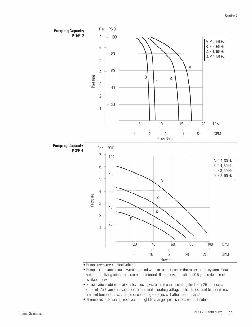


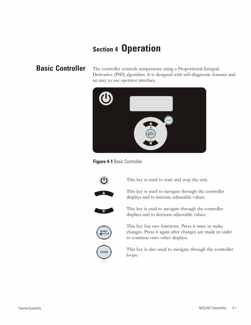

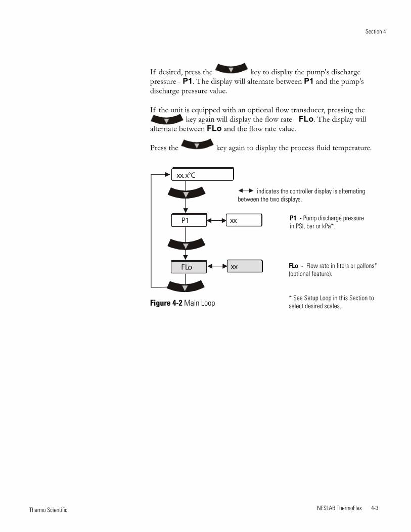

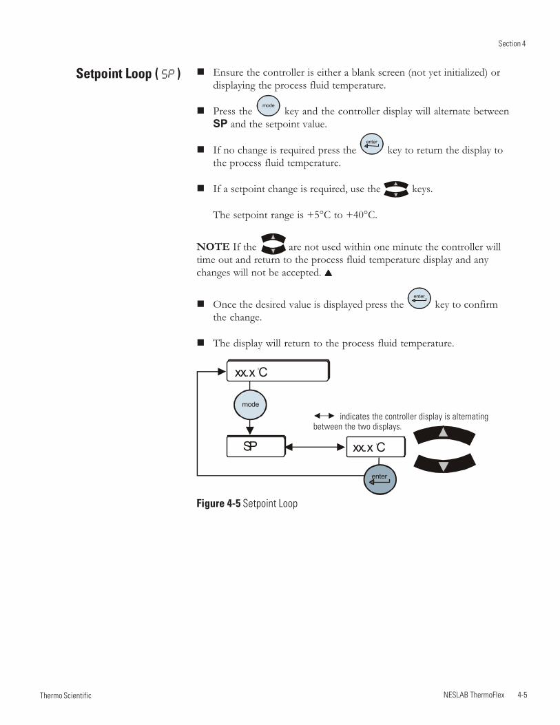


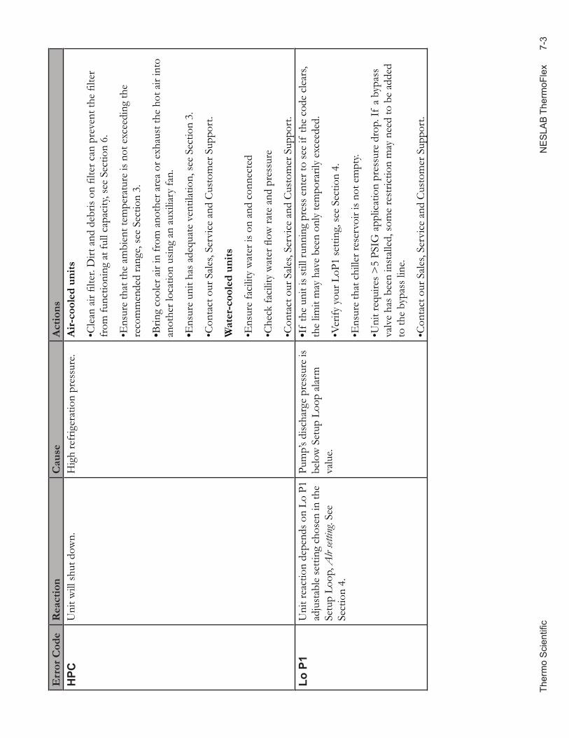


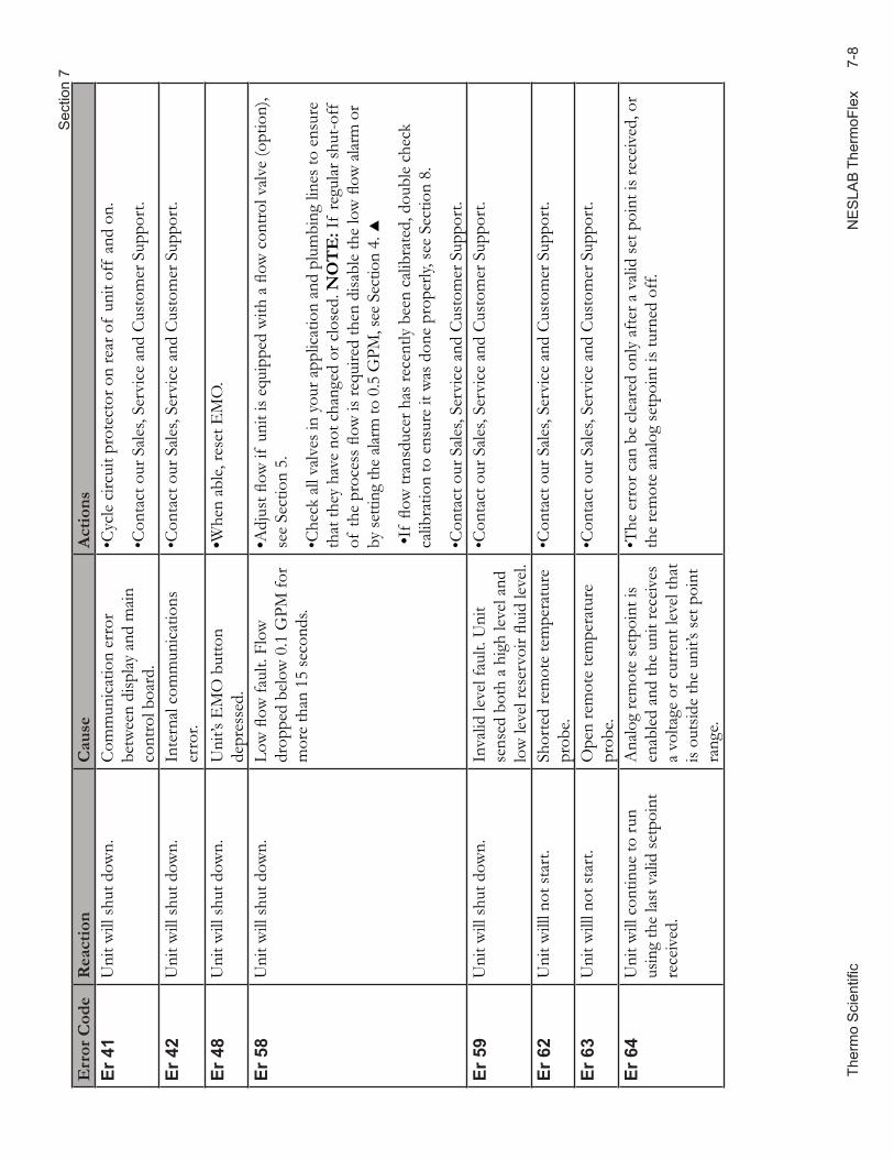


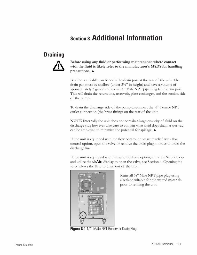


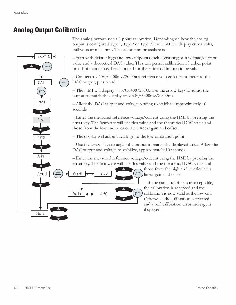


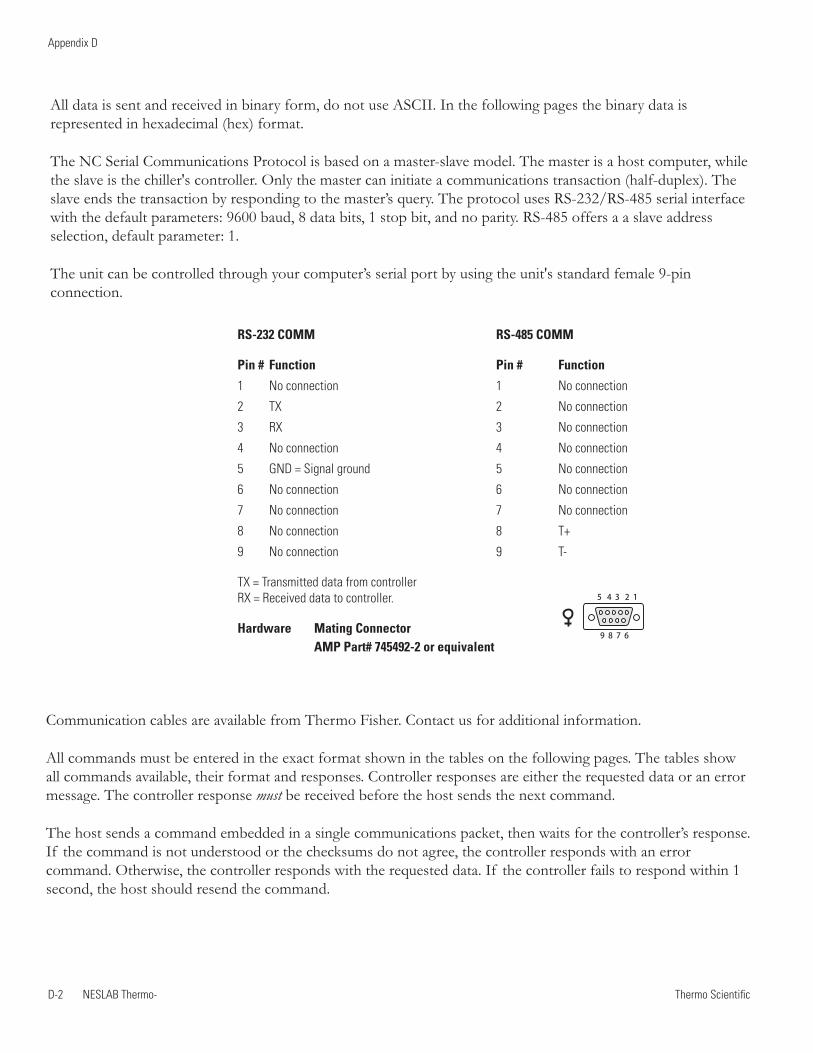


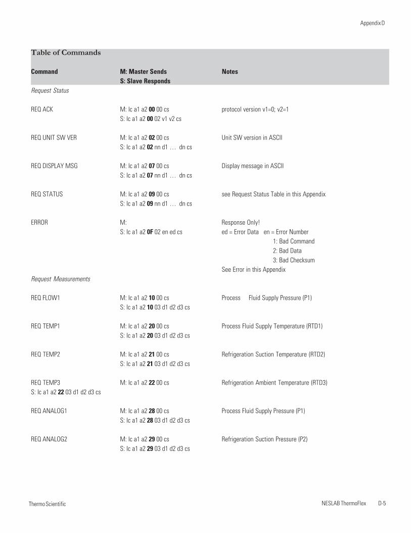


![Welcome! [] Webinars/Webinar...Welcome! Webinar #17: Total Plant Cost in Thermoflex 21 Nov 2017 Agenda: * Introduction - PEACE Components in Thermoflex - Cost estimation in TFX, traditional](https://static.documents.pub/doc/80x56/607d21a0c20bc66fed20bca0/welcome-webinarswebinar-welcome-webinar-17-total-plant-cost-in-thermoflex.jpg)


