7/24/2019 Thermodynamic Analysis of Solid Oxide Fuel Cell-Gas Turbine Systems Operating With Various Biofuels (1)
http://slidepdf.com/reader/full/thermodynamic-analysis-of-solid-oxide-fuel-cell-gas-turbine-systems-operating 1/14
Thermodynamic Analysis of Solid Oxide
Fuel Cell Gas Turbine Systems Operating with Various BiofuelsH. C. Patel1*, T. Woudstra1, P. V. Aravind1
1 Process and Energy Laboratory, Delft University of Technology, Section Energy Technology, Leeghwaterstraat 44, 2628CA Delft, TheNetherlands
ReceivedApril 20, 2012; acceptedAugust 27, 2012
1 Introduction
Solid oxide fuel cell (SOFC) systems hold great promise as
a sustainable power source because of their high efficiency,
fuel flexibility and ability to be combined with other systems
to make hybrids with even higher efficiency. The SOFC can
be operated with various fuels because of the high operation
temperature and with the catalyst used some fuels can be
even internally reformed. Thus, there is an opportunity to usecarbonaceous biofuels in the SOFC wherein they can be
internally or externally reformed to give hydrogen for the
electrochemical reaction [1, 2]. Biomass can be a sustainable
fuel with correct regulations but biomass in itself is not very
easy to burn without environmental impact. It can be benefi-
cial to convert raw biomass into secondary liquid or gaseous
fuels with better properties like density, energy density,
transportability, etc. Biomass can be easily converted into
methanol, ethanol, and synthesis gas (CO + H2). Ammonia
and methane can be obtained from biological sources or from
waste in a sustainable manner and eventually hydrogen can
also be produced from biomass using thermal or biological
processes [2–7]. SOFC-gas turbine (SOFC-GT) systems offer
an opportunity for using biomass to meet energy require-
ments with highest possible efficiency and hence least envir-
onmental impact.
The fuel flexibility of the SOFC is a topic of growing inter-
est and various experimental as well as theoretical studies are
available in literature about SOFCs operating on fuels like
methanol, ethanol, and methane etc. [3, 5–9]. Considering the
present scenario it is not very clear what fuel would even-
tually be used if at all a single fuel is used as the futureenergy carrier. Economic, safety, and environmental concerns
would rule out some of the fuels and phase in others. All such
fuels are explored as energy carriers for the future as all of
them provide some advantages but their use in an SOFC
environment is not fully explored on a thermodynamic basis
especially when compared to each other.
A comprehensive thermodynamic analysis of an SOFC
system operating with various fuels can give invaluable infor-
mation on the operating characteristics of each fuel, the ther-
modynamic limitations, the effect on the balance of plant sys-
[*] Corresponding author, h.c.patel @tudelft.nl
Abstract
Solid oxide fuel cell–gas turbine (SOFC-GT) systems provide
a thermodynamically high efficiency alternative for power
generation from biofuels. In this study biofuels namely
methane, ethanol, methanol, hydrogen, and ammonia are
evaluated exergetically with respect to their performance at
system level and in system components like heat exchan-
gers, fuel cell, gas turbine, combustor, compressor, and the
stack. Further, the fuel cell losses are investigated in detail
with respect to their dependence on operating parameters
such as fuel utilization, Nernst voltage, etc. as well as fuel
specific parameters like heat effects. It is found that the heateffects play a major role in setting up the flows in the system
and hence, power levels attained in individual components.
The per pass fuel utilization dictates the efficiency of the fuel
cell itself, but the system efficiency is not entirely dependent
on fuel cell efficiency alone, but depends on the split
between the fuel cell and gas turbine powers which in turn
depends highly on the nature of the fuel and its chemistry.
Counter intuitively it is found that with recycle, the fuel cell
efficiency of methane is less than that of hydrogen but the
system efficiency of methane is higher.
Keywords: Biofuels, Exergy, SOFC-GT, Solid Oxide FuelCell, Solid Oxide Fuel Cell Gas Turbine, System Studies
FUEL CELLS 12, 2012, No. 6, 1115–1128 © 2012 WILEY-VCH Verlag GmbH & Co. KGaA, Weinheim 1115
ORI GI N
AL RE S E AR C HP AP E R
DOI: 10.1002/fuce.201200062
7/24/2019 Thermodynamic Analysis of Solid Oxide Fuel Cell-Gas Turbine Systems Operating With Various Biofuels (1)
http://slidepdf.com/reader/full/thermodynamic-analysis-of-solid-oxide-fuel-cell-gas-turbine-systems-operating 2/14
Patel et al.: Thermodynamic Analysis of Solid Oxide Fuel Cell Gas Turbine Systems Operating
tem and resulting thermodynamic effects. Optimization of
such a system with individual fuels will point out the effects
of the fuel chemistry on the overall systems as well as each
component.
The energy efficiency of systems is better understood withthe help of the exergy concept. The second law of thermody-
namics defines a difference in the quality of energy. Exergy
refers to the part of heat (or any other form of energy) which
is available for useful work. Maximum work can be obtained
in a thermodynamically reversible process and non-idealities
in a system cause a departure from reversibility resulting in
lower efficiency. Combustion is always associated with large
exergy destruction. In fuel cells electrochemical processes of
electron transfer is nearer to reversibility and hence has much
higher thermodynamic efficiency depending on temperature.
Among the various fuel cell types we consider the SOFC
because of its high thermodynamic efficiency [10–12]. The
main advantage lies in the high grade heat available at the
fuel cell exhaust (1,073–1,273 K). This can be used to drive a
bottoming cycle like a steam cycle or GT cycle to utilize the
heat and unused fuel to produce power. Such hybrid systems
have been studied extensively in literature and pros and cons
of various bottoming cycles have been detailed [9, 13].
We choose the GT cycle because of its relative simplicity,
high power to weight ratio and ability to use high tempera-
ture and pressure gas to produce electricity efficiently. Also,
the fuel cell benefits from the increased pressure, increasing
overall efficiency.
In the combined system the fuel cell exhaust gas is burnt
and the flue gas is passed through a GT. The high tempera-ture GT exhaust gas is used to preheat inlet streams of the
fuel cell resulting in good heat recovery. There is still residual
heat which can be used to generate steam used for the
reforming reaction of the hydrocarbon to form hydrogen.
These options are considered in sections below and described
in more detail.
With this arrangement we reduce the stack losses and uti-
lize the SOFC exhaust completely resulting in a more efficient
system than either of the above alone. Efficiencies of the order
of 70–80% are expected from such a hybrid system [4, 5, 10–
12, 14]. Optimization strategies have also been studied for
SOFC-GT integration mostly dealing with system configura-
tion [15, 16]. Scupita et al. [17] studied the effect of fuel com-
position limited to varying the composition between CH4,CO,
CO2, N2, a n d H2 mainly targeting biomass derived gas
streams. Some authors have focused on a fixed GT design as
commercially available “off the shelf” designs may not be
able to perform optimally in the hybrid system not specifi-
cally designed for a particular turbine [18, 19].
Previous studies on SOFC-GT systems have been mostly
focusing on optimizing a system for a particular fuel or two
fuels, providing a comparison of systems based on parame-
ters like operating pressure, temperature, steam to carbon
ratio, etc. [4, 10–12]. Leucht et al. [20] studied the dynamic
performance of an SOFC-GT system through various opera-tion strategies in order to be able to follow a particular load
for the system. They concluded that pressurizing the fuel cell
rather than operating at normal pressures is advantageous.
Song et al. [18] studied a tubular cell with a quasi 2D model
allowing prediction of temperatures and flow in a particular
direction in the cell. They concluded a co-flow arrangement ismore efficient than the counter-flow. Kuchonthara et al. [21]
studied further energy recuperation techniques in an SOFC-
GT system considering steam (through a heat recovery steam
generator) and heat recuperation and found that steam recup-
eration can improve the overall system efficiency as well as
specific power. Similarly Yi et al. [22] applied an intercooled
GT to the SOFC-GT hybrid cycle. An efficiency of 75.8% elec-
trical was achieved using natural gas (NG) as fuel. Multistage
oxidation using SOFCs in a hybrid SOFC-GT system was
found to increase the efficiency and limit the temperature gra-
dients [23]. Methanol and kerosene were investigated as fuels
by Santin et al. [9] with respect to thermodynamic as well as
economic criteria with methane as the reference fuel. For an
operating pressure of 4 bar the efficiency was found to be
64.5% for the reference case of methane. The maximum effi-
ciency obtained was 64.8% for methanol and 54.9% for kero-
sene. The economic performance was better with methanol
than with other systems. Chan et al. [24] in their study mod-
eled a tubular SOFC with the losses split into Ohmic, activa-
tion and concentration polarizations for an NG fed SOFC-GT
system coupled with a heat recovery steam generator. An
electrical efficiency of 61.9% was obtained. The effect of pres-
sure, flow rates was studied in a separate study [25].
But the exergy criterion is not considered by many. Ener-
getic criterion does not differentiate between the qualities of the various energy sources. This can be achieved using
exergy which takes into account the second law of thermody-
namics and that not all forms of energy are equal in quality.
Exergy analysis of SOFC-GT system has been provided by
Calise [26] where individual components and exergy losses
are identified for a single gas composition. Motahar and
Alemrajabi [27] studied a tubular SOFC-GT system with
steam injection. Individual components were identified and
losses in each were presented. Using steam injection it was
found that the stack losses could be brought down signifi-
cantly increasing efficiency from 58.28 to 65.34%. The system
exhaust temperature was brought down from 381 to
130.27 °C. Granovskii et al. [12] studied methane conversion
in an SOFC-GT system using exergy where the maximum
thermodynamic efficiency reached as high as 70–80%. Bavar-
sad [28] performed energy and exergy analysis of a NG fed
SOFC-GT system based on parameters like pressure ratio and
flow rates. The first and second law efficiencies achieved
were 65.62 and 59.32%, respectively. He also concluded that
higher air or fuel flow rates have a negative influence on the
efficiency. Aravind et al. [5] on the other hand found no sig-
nificant influence of pressure ratio on the efficiency of a sys-
tem comprised of a biomass gasifier with an SOFC-GT.
Excluding the gasifier the major system components contri-
buting to exergy losses were the GT and compressors. A highefficiency of 73% was obtained for a gasifier SOFC-GT system
ORIGINALRESEARCH
PAPER
1116 © 2012 WILEY-VCH Verlag GmbH & Co. KGaA, Weinheim FUEL CELLS 12, 2012, No. 6, 1115–1128www.fuelcells.wiley-vch.de
7/24/2019 Thermodynamic Analysis of Solid Oxide Fuel Cell-Gas Turbine Systems Operating With Various Biofuels (1)
http://slidepdf.com/reader/full/thermodynamic-analysis-of-solid-oxide-fuel-cell-gas-turbine-systems-operating 3/14
Patel et al.: Thermodynamic Analysis of Solid Oxide Fuel Cell Gas Turbine Systems Operating
where multiple fuel cell stages were applied [28]. Similarly
Haseli et al. [30, 31] provide an exergy analysis of an SOFC-
GT system with the effect of operating parameters like ambi-
ent temperature and compressor pressure. An efficiency of
60.6% was obtained at the compression ratio of about 4 whichwas found to be the optimum. Douvartzides et al. [32] used
exergy analysis to analyze an SOFC power plant fed with
methane or ethanol using an external steam reformer. They
concluded that methane fed power plant was more efficient
than the ethanol fed one irrespective of temperature (within
allowable limits) and reforming factor. Efficiencies of the
order of 65–75% were obtained depending on temperature
and fuel. Chan et al. [33] performed exergy analysis of the
SOFC without the GT cycle exploring the effect of current
density and temperature for hydrogen and methane fuels.
The first and second law efficiencies for hydrogen and
methane are 50.97 and 52.8% and 62.19 and 59.96%, respec-
tively.
Other studies mainly focus on single fuels and optimizing
of components like GTs, steam turbines, and various types of
fuel cells or operating conditions and parameters like fuel uti-
lization, operating pressure, etc. [2, 4, 5, 11, 12, 14, 34–37].
Though these are important in identifying operating con-
ditions, to gain deeper insight into operating characteristics
of different fuels, it is required that various fuels be compared
at a particular operating condition and individual compo-
nents of the system be identified and losses within each com-
ponent be quantified. A comprehensive study across such
broad range of fuels based on exergy by identifying individu-
al components is absent as far as the authors knowledge goes.In this study various fuels are compared based on exer-
getic criteria as it provides a truer measure of work obtain-
able. The influence of individual components on the overall
efficiency for different fuels, when judged with the exergy cri-
teria is an important method for arriving at more refined sys-
tem concepts with high efficiency and optimal operating con-
ditions. Thus, in this study it is aimed at arriving at a high
efficiency SOFC-GT system and identifying parameters cru-
cial to its operation. Individual components are identified in
addition to the operating parameters and the efficiency of
each component is discussed for the fuel considered using
exergy.
2 Fuel Options
Hydrogen is considered in this study because of the basic
reaction of the fuel cell being hydrogen oxidation to produce
water. Hydrogen is studied on a large scale by many organi-
zations toward the development of a sustainable hydrogen
economy and thus serves as an ideal case.
Since cost of hydrogen and its storage is an issue NG is a
viable alternative. NG is readily available through pipe net-
work or through tanks (liquefied NG). Further, NG is cheap
and has lesser pollutants than diesel oil. Another advantage
with NG is that in the SOFC it is internally reformed, so aseparate reformer is not always required. In the SOFC, NG
components (CH4 mainly with some higher hydrocarbons)
undergo reforming internally as this reaction is supported by
the electro-catalyst used in the anode. Thus NG (with steam
addition) can be used directly as a feedstock in the SOFC
leading to a more simple and feasible system for the time being. It is interesting to note that this change in fuel will
already bring about a reduction in CO2 emissions resulting
from the lower C content of the fuel as compared to diesel oil.
For the purpose of modeling NG is considered as methane
[1, 14]. Methane is taken as the basis for comparison of other
fuels.
Biomass-based fuels are under a lot of discussion. Because
of the high temperatures in the SOFC it is possible to use a
variety of fuels. With proper legislation and production tech-
niques, biomass and waste derived fuels like ammonia,
dimethyl ether (DME), ethanol, methanol, biodiesel can all be
considered as sustainable carbon neutral sources [8, 26, 38, 39].
Fuels such as ammonia have received attention lately as alter-
natives to conventional diesel oil for fuel cell applications
[40]. These if properly regulated can indeed be sustainable
and have zero emissions by being conserved in the carbon
cycle. Ammonia is an interesting alternative as it is actually
commercially available in large quantities. It is carbon free
and has very high hydrogen content in addition to being
almost non-flammable [6]. The products of ammonia reaction
in the SOFC are merely nitrogen and water and thus no
greenhouse gas emissions [6–8, 10]. Ammonia is converted
into its constituent N2 and H2 and the H2 is further utilized in
the normal H2–H2O cell reaction [41]. There is minimal
production of NOx at operating conditions showing that theN2 is mostly inert in the cell. On the other hand ammonia is
toxic and can be detected by its smell even at levels of few
ppms [6, 7].The technology of the cell itself is not yet well
developed and accepted.
Ethanol and methanol are biomass derivatives which can
be obtained from synthesis gas as well as biomass conversion
through biological processes. Compared to NG the reforming
requirement is different as the major component of NG is
methane, the simplest of hydrocarbons, while methanol is
also a C1 compound, while ethanol is possibly more difficult
to break. Energy density of methanol is high and this might
provide an interesting option for fuel supply if methanol can
be commercially produced and distributed [39]. Ethanol is
already produced on a large scale biologically but competi-
tion with the current feedstock, which is mainly from food
needs to be considered. A broad comparison is given in Table
1 for the various fuels which will be considered in this study
[8].
Synthesis gas, which will be produced by reforming of the
above fuels, has been studied extensively as a fuel. With the
SOFC there is no need to remove CO. With steam addition
this can be converted to H2 using the water gas shift (WGS)
reaction. At the temperatures used in SOFC this reaction is
quite favorable. This is desirable as the OCV of CO–CO2 is
lower than that of H2–H2O [1]. It is assumed here that only
ORI GI N
AL RE S E AR C HP AP E R
FUEL CELLS 12, 2012, No. 6, 1115–1128 © 2012 WILEY-VCH Verlag GmbH & Co. KGaA, Weinheim 1117www.fuelcells.wiley-vch.de
7/24/2019 Thermodynamic Analysis of Solid Oxide Fuel Cell-Gas Turbine Systems Operating With Various Biofuels (1)
http://slidepdf.com/reader/full/thermodynamic-analysis-of-solid-oxide-fuel-cell-gas-turbine-systems-operating 4/14
Patel et al.: Thermodynamic Analysis of Solid Oxide Fuel Cell Gas Turbine Systems Operating
WGS reaction occurs and all CO is converted to CO2 through
the shift reaction.
3 Modeling and Input Parameters
For the purpose of this study four fuels have been chosen
as all of these can be sustainably manufactured from biologi-
cal sources and it would be of importance to explore these in
context of SOFC systems.
The fuels studied are
(i) Methane
(ii) Ammonia
(iii) Hydrogen
(iv) Ethanol
(v) Methanol
The Lower Heating Value(LHV) and Exergy values are
provided in Table 1 for the above fuels. Cycle Tempo is a in-
house software developed at TU Delft which can be used for
thermodynamic analyses and optimization of power cycles
including fuel cells [42]. Cycle Tempo employs a Gibbs free
energy minimization based routine for equilibrium calcula-
tions in the fuel cell and combustor. For more details about
these models the reader is referred to the manual of Cycle
Tempo [42].
A model was developed in Cycle Tempo for a combined
SOFC-GT system considering internal reforming for various
fuels keeping the heat exchanger network same at same val-
ues. In the model a choice is made to fix the GT power at
30 kW and let the fuel cell output vary. The GT is not the
same in all cases but has the same power rating. The conse-quence of the fuel cell power varying is that the fuel cell will
be of a different size (area) for different fuels. For the purpose
of this study the systems are compared at design load only.
The pressure of 3 bar is chosen keeping into mind that this is
similar to a recuperating turbine and is more efficient at
around this pressure ratio [2]. Also previous studies have
shown that this is more or less near to an efficient point of
operation for the combined system [26, 30].
Methane, ethanol, methanol, ammonia and hydrogen are
all available in the library of FluidProp [43] which is used by
Cycle Tempo. For the detailed equations and properties the
reader is referred to the manual of Cycle Tempo and Fluid-
Prop [42, 43].
The model used is depicted in Figure 1 along-with various
subsystems considered for the analysis in later sections. It is
assumed here that all the fuels are completely internally
reformed at the SOFC anode. This is based on the assumption
that no carbon deposition occurs in the pipes upstream the
fuel cell. The feed is 20% water, alongwith the respective fuel
at 288 K, 1.013 bar. Because of the recycle there is always
enough steam in all cases. The steam to carbon ratios
achieved at the inlet of the fuel cell are 6.2, 6.9, and 3.8 for
methane ethanol and methanol, respectively. The fuel and
water is compressed to 3.065 bar in the compressor and
passed through successive heat exchangers to recover heatfrom the exhaust stream of the GT. The exact outlet tempera-
ture for the heat exchangers for each fuel is different based on
the heat available after the exhaust of GT. This fresh fuel is
mixed with recycled stream from the anode in order to obtain
a temperature of 1,173 K. On the air side fresh air is com-
pressed from 1.013 to 3.04 bar and preheated in heat exchan-ger and mixed with the recycle stream to again obtain a tem-
perature of 1,173 K. The exhaust streams from the fuel cell
are mixed and combusted in the combustor and subsequently
fed to the GT. As mentioned before the exhaust from the GT
is used to preheat the incoming streams and then given out in
the stack.
3.1 Calculation and Model Rules
Cycle Tempo utilizes Gibbs free energy minimization to
determine equilibrium conditions in the Fuel Cell and Com-
bustor. For this particular model the power level of the tur-
bine (fixed at 30 kW) is in turn used to calculate the mass
flow through the turbine and other equipment. Current in the
fuel cell is determined by the specified fuel utilization and
mass flow determined from GT/Combustor as well as set
temperatures. The mass flow ratio at cathode and anode is
determined by energy balance to obtain specified tempera-
tures. The current is then calculated from the mass flows and
the fuel utilization specified. Hence, active area of the cell
and the equivalent resistance is also calculated from the volt-
age and the current density. The enthalpy at turbine and com-
pressor outlet is calculated from the isentropic efficiency.
Other parameters used, common to all fuels are given in
Table 2.In each case the cell voltage is adjusted to obtain an
equivalent resistance of 5 × 10⁻⁵Xm2. Heat exchangers are
provided to ensure an inlet temperature of 1,173 K to cathode
and anode. Since this is not fully possible utilizing only the
GT exhaust, the exhaust gases from fuel cell are re circulated
to obtain the required inlet temperature. This recirculation is
also used in order to prevent large thermal gradients across
the cell and also equilibrate composition. It is noted here that
because of the recycle even though the overall utilization is
fixed it can vary per pass. The utilization based on fuel used in
the cell is called the per-pass utilization and the utilization
based on fresh fuel is called the overall utilization. The
amount of recycle is calculated on the basis of the inlet tem-
perature (which is specified) and the temperature at the out-
let of the heat exchangers. Practically also maintaining of a
steady operating temperature is essential.
The fuels are used as available from the library of Cycle
Tempo and are fed alongwith 20% water. The enthalpy for
vaporization is provided in subsequent heat exchangers.
Internal reforming of methane to CO and H2 and subsequent
WGS is calculated by Cycle Tempo based on equilibrium
under those conditions of temperature and pressure. In inter-
nal reforming SOFC module of Cycle Tempo, the equilibrium
compositions are calculated first and then the fuel cell param-
eters are calculated based on this composition as shown inFigure 2. T react and Preact are the temperature at which
ORIGINALRESEARCH
PAPER
1118 © 2012 WILEY-VCH Verlag GmbH & Co. KGaA, Weinheim FUEL CELLS 12, 2012, No. 6, 1115–1128www.fuelcells.wiley-vch.de
7/24/2019 Thermodynamic Analysis of Solid Oxide Fuel Cell-Gas Turbine Systems Operating With Various Biofuels (1)
http://slidepdf.com/reader/full/thermodynamic-analysis-of-solid-oxide-fuel-cell-gas-turbine-systems-operating 5/14
Patel et al.: Thermodynamic Analysis of Solid Oxide Fuel Cell Gas Turbine Systems Operating
reforming and WGS reaction equilibrium compositions are
calculated and T fcel and Pfcel are fuel cell temperature and
pressures.
Ammonia also undergoes thermal decomposition to form
constituent N2 and H2. The hydrogen is utilized as fuel in the
normal fuel cell reaction to produce water. In Cycle Tempo
calculations, all the fuels are completely reformed into hydro-
gen and constituent molecules (CO/CO2/N2).
Mass flows in each apparatus is calculated by mass and
energy balance. Overall the number of equations must be
equal to number of pipes. In this case the oxidant to fuel ratio
in the combustor is determined by the airflow and hence cool-
ing requirement of the fuel cell.
In the fuel cell module in Cycle Tempo the inlet gas is first
taken to equilibrium. The current flow I , voltage V , and
power Pe are then calculated. The current can be calculatedfrom the flow to the anodeUm,a,in andthe fuelutilization U f as
I main
Ma2F yH2O yCO 4 yCH4
U f (1
where Ma is the molar mass, y i are the respective mole frac-
tions of the species and F is the Faradays constant. From this
the flow of oxygen from the cathode is calculated. Since the
temperature at the outlet is set, the airflow can be calculated.
Further to calculate the voltage V , power Pe, and current den-
sity im a one dimensional model is used. The temperature is
assumed constant in the cross section perpendicular to the
direction of fuel flow. Local variables of current density ix,
voltage V x, and concentrations yx are calculated.
The local Nernst voltage V rev,x is calculated as
V revx V 0rev RT
2F
ln y
12
02 c yH2
yH2O
p12
cell (2
Fig. 1 Model in Cycle Tempo with subsystems.
ORI GI N
AL RE S E AR C HP AP E R
FUEL CELLS 12, 2012, No. 6, 1115–1128 © 2012 WILEY-VCH Verlag GmbH & Co. KGaA, Weinheim 1119www.fuelcells.wiley-vch.de
7/24/2019 Thermodynamic Analysis of Solid Oxide Fuel Cell-Gas Turbine Systems Operating With Various Biofuels (1)
http://slidepdf.com/reader/full/thermodynamic-analysis-of-solid-oxide-fuel-cell-gas-turbine-systems-operating 6/14
Patel et al.: Thermodynamic Analysis of Solid Oxide Fuel Cell Gas Turbine Systems Operating
where T is the temperature, V 0rev the standard reversible vol-
tage, R the universal gas constant yi the mole fraction, and
pcell is the pressure. If the voltage losses are assumed to be
negligible in the x direction then the cell voltage would be
constant over the fuel cell. Hence
DV x V revx V (3
where D
V x
is the loss in voltage. If Req is the equivalent cellresistance then the current density can be calculated as
ix DV xReq
(4
Over the complete area A of the cell we can use
I
A
U f
Req
U f
0
1
V revV dk
(5
where k is the reaction ordinate. Hence, the power can be cal-
culated.
For a known power of GT, the mass flow can be calculatedfrom the specific enthalpy as given below.
The outlet enthalpy for a compressor is obtained from
ho hi hos hi
gs(6
And for a GT it is found as
ho hi gshi hos (7
where ho is the specific enthalpy at the outlet, h i the specific
enthalpy at the inlet, ho,s the specific enthalpy at the outlet for
an isentropic process, and gs the isentropic efficiency.
Exergy efficiency can be defined as
gEx RExproducts
RExsource(8
where, RExproducts is the exergy flow that can be considered a
product of the system while RExsource is the exergy of that
part of the ingoing process that can be considered as neces-
sary to form the product. Depending on particular problemthe Exproducts and Exsource need to be specified. In the case of a
Fig. 2 Cycle Tempo calculations for fuel cell.
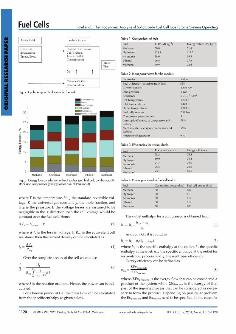
Fig. 3 Exergy loss distribution in heat exchanger, fuel cell, combustor, GT,stack and compressor (exergy losses as% of total input).
Table 1 Comparison of fuels
Fuel LHV (MJ kg–1) Exergy values (MJ kg–1)
Methane 50.0 51.4
Hydrogen 121.4 117.5
Ammonia 18.6 19.8
Ethanol 26.8 27.6
Methanol 19.9 22.5
Table 2 Input parameters for the models.
Parameter Value
Fuel utilization (based on fresh fuel) 85%
Current density 2,500 Am–2
Inlet pressure 1 bar
Resistance 5 × 10⁻⁵Xm2
Cell temperature 1,223 K
Inlet temperatures 1,173 K
Outlet temperatures 1,273 K
Fuel cell pressure 2.97 bar
Compressor pressure ratio 3Isentropic efficiency of compressor and
turbine
78%
Mechanical efficiency of compressor and
turbine
98%
Efficiency of generator 90%
Table 3 Efficiencies for various fuels.
Fuel Energy efficiency Exergy efficiency
Methane 78.3 75.5
Hydrogen 69.0 70.4
Ammonia 74.7 70.0
Ethanol 75.5 70.8
Methanol 73.1 68.5
Table 4 Power produced in fuel cell and GT.
Fuel Gas turbine power (kW) Fuel cell power (kW)
Methane 30 139
Hydrogen 30 81
Ammonia 30 112
Ethanol 30 117
Methanol 30 100
ORIGINALRESEARCH
PAPER
1120 © 2012 WILEY-VCH Verlag GmbH & Co. KGaA, Weinheim FUEL CELLS 12, 2012, No. 6, 1115–1128www.fuelcells.wiley-vch.de
7/24/2019 Thermodynamic Analysis of Solid Oxide Fuel Cell-Gas Turbine Systems Operating With Various Biofuels (1)
http://slidepdf.com/reader/full/thermodynamic-analysis-of-solid-oxide-fuel-cell-gas-turbine-systems-operating 7/14
Patel et al.: Thermodynamic Analysis of Solid Oxide Fuel Cell Gas Turbine Systems Operating
power plant, the electrical exergy efficiency of the system is
given as
gExel RPelout RPelin
Exfuelin(9
where RPel,out is the electrical output of the system and RPel,in
is the input electrical power. Exfuel,in is the exergy of the fuel
that is fed to the system.
For more details, the reader is referred to the work of Ara-
vind et al. [5] and the manual of Cycle Tempo [42].
4 Results and Discussion
The system with methane is taken as a basis and is
explained in detail while results are presented for the other
systems for comparison. With the GT power fixed at 30 kW
the fuel cell produces 139 kW based on the temperatures spe-
cified and recycle ratios obtained. The air compressor con-
sumes 29.6 kW while the recirculation fans consume 1.4 kW
of power. The fuel cell operating voltage for a resistance of
5 × 10⁻⁵Xm2 is 0.795 V. The corresponding area of the fuel
cell is 70.134 m2. The overall utilization is fixed at 85% while
the per pass utilization achieved, because of the recycle is
76.5%. The air recycle ratio is 0.1 and the fuel recycle ratio is
0.7. With this system the energy efficiency attained is 78.3%
and the exergy efficiency is 75.5%.
Efficiencies are obtained for all the fuels using the model
and input parameters are shown in Table 3.
The (system using) methane is clearly most efficient fol-
lowed by ammonia and ethanol. This trend is not followed bythe exergy efficiency. The exergy efficiency of methane is
highest but ammonia has a much lower exergy efficiency
compared to its energy efficiency and the exergy efficiency of
hydrogen is almost similar to that of ethanol even though the
energy efficiency of ethanol is around 6.5% more than that of
hydrogen.
The distribution of energy and exergy efficiencies can be
because of flows, the heat exchangers, the combustor or the
fuel cell itself. Another significant factor is the split between
the fuel cell and GT power as we expect that higher fraction
of power produced in the fuel cell would lead to higher effi-
ciency.
As shown in Table 4 the fuel cell produces most power in
the methane system and immediately points toward its high
energy and exergy efficiency. The low energy efficiency of
hydrogen is also clearer because of the relatively lower frac-
tion of power produced in the fuel cell. The energy efficiency
follows from the split in the GT and SOFC power but the
exergy efficiency of the various fuels do not follow this trend.
Losses in various subsystems can be quantified and a dis-
tribution is presented based on the following subsystems –
heat exchangers, combustor, fuel cell, GT, and compressor
(recirculation fans in addition to air and fuel compressors).
Each of these subsystems shows a different pattern in losses
for each fuel and based on the operating parameters the behavior can be understood better. It is noted here that losses
Fig. 4 Fuel utilization per pass of fuel cell alongwith exergy loss in fuel cell
for all fuels.
Fig. 5 Nernst voltage (V) based on compositions at the end of the cell andactual cell voltage.
Fig. 6 IV characteristics for fuel utilization of 76.5% for H2 and methane with no recirculation.
ORI GI N
AL RE S E AR C HP AP E R
FUEL CELLS 12, 2012, No. 6, 1115–1128 © 2012 WILEY-VCH Verlag GmbH & Co. KGaA, Weinheim 1121www.fuelcells.wiley-vch.de
7/24/2019 Thermodynamic Analysis of Solid Oxide Fuel Cell-Gas Turbine Systems Operating With Various Biofuels (1)
http://slidepdf.com/reader/full/thermodynamic-analysis-of-solid-oxide-fuel-cell-gas-turbine-systems-operating 8/14
Patel et al.: Thermodynamic Analysis of Solid Oxide Fuel Cell Gas Turbine Systems Operating
such as nodes are not included in the distribution depicted in
Figure 3.
Methane has high system efficiency with higher losses in
stack, GT combustor and fuel cell than compressor or heat
exchangers. The higher loss in the fuel cell can be attributedto the high fraction of power that is produced by the fuel cell.
Ammonia, methanol, and ethanol all have high fuel cell losses
inspite of the internal reforming reactions to remove heat
from the cell. Hydrogen is the most efficient exergetically as
far as the fuel cell itself is concerned with methanol being the
least efficient. The auxiliary power consumption (compres-
sors) is also very indicative of the reasons for the losses. The
auxiliary power consumption of hydrogen is highest fol-
lowed by methanol, ethanol, ammonia and the lowest is for
methane. This is because of larger airflows and compressors
required for both ammonia and hydrogen which mostly also
is followed by large fraction of GT power. A high GT power
fraction means that the combustor as well as the compressor
has higher flows leading to higher losses. The hydrogen sys-
tem has the highest losses in GT, compressor, and combustor.
From the distribution it seems likely that the internal
reforming reaction of ammonia, ethanol, and methanol influ-
ences the distribution of the losses especially the high losses
in the fuel cell. The above picture presents questions about
the source of these losses and corresponding influence on the
system performance.
Calculation of the flows in the system is based on the
power and temperatures and hence heat effects play an
important part in determining the flow through each of the
components. In addition to the normal heat exchangers thereis an additional source of heat in the fuel cell as well as a sink.
The fuel cell produces heat with fuel oxidation, while the
reforming reactions consume heat. Based on this balance the
flows in the system are set. The recycle adds some more com-
plexity as the flows are adjusted for maintaining temperature
at the fuel cell inlet which in turn sets the per pass utilization
in the fuel cell.
For each mole of H2 in an ideal fuel cell if we neglect all
other irreversibilities, there is around 65 kJ mol–1 of heat pro-
duced (using simply the difference between change in
enthalpy and Gibbs free energy) at around 1,223 K. For an
operating cell this will of course be higher with other irrever-
sibilities like Ohmic, activation, etc. Now, if we consider sim-
ple steam reforming reactions for each fuel then we may be
able to look at the losses qualitatively from the point of view
of heat utilization. For methanol and ammonia decomposi-
tion is considered. Reaction enthalpies are calculated for each
fuel at 1,223 K according to stoichiometric quantities, as
shown in Table 5.
Methane requires 227.2 kJ mol–1 of heat for reforming
while producing 3 moles of H2 at 1,223 K. Thus, per mole of
hydrogen the amount of heat required is large and if we con-
sider other irreversibilities in the cell the heat can for a large
part be easily taken away from the cell by the reforming reac-
tion of methane. The air to fuel ratio is least for the fuel cellwith methane fuel is the least showing very good heat use
within the cell. Ethanol however produces 4 moles H2 requir-
ing 308.2 kJ mol–1 heat. However, the air to fuel ratio is much
higher than methane. In case of Ammonia the reaction
requires 55.8 kJ mol–1 producing 1.5 moles of H2. This still
serves to remove heat, but is very low compared to the otherfuels corresponding air factor and GT powers are higher
when compared to other fuels. The nitrogen is not further
used in the WGS reaction which provides for another heat
sink within the cell as compared to the other fuels where the
WGS would tend to increase the heat release. Thus, the heats
from electrochemical and reforming reactions would tend to
be even more imbalanced. The nitrogen which is produced
does act as a diluent but serves to remove heat from the cell
as well. Methanol has an intermediate heat requirement
which is clear from its low heat requirement for reforming.
Now the picture is much clearer as to the reasons for exergy
losses in the system. There is a lot of excess heat in case of
ammonia ethanol and methanol which leads to much higher
cathode air flows and thus higher exergy losses. The WGS
reaction also plays a part in determining the heat released as
it is exothermic and will decrease the heat sink that is pro-
vided by the reforming reactions. In Cycle Tempo, as men-
tioned in Section 3, equilibrium compositions are calculated
based on reforming as well as WGS reactions. For the sake of
the discussion in the next two paragraphs only, we neglect
the WGS reaction which is not entirely accurate, but as can be
seen the comparison remains more or less similar qualita-
tively. We would like to point out again that in the calcula-
tions done by Cycle Tempo, the WGS reaction included for
heat as well as mass balances.If we now consider the recycle ratios for each of the fuels
then we can also explain why there is a distribution of recycle
ratios for fuel and air. This will indicate the amount of heat
which is recycled compared to fresh air/fuel which is taken
in. The recycle ratio is set by the inlet temperature which is
prescribed and heat recovery which is achieved from the GT
exit.
Methane and ammonia have low air recycle ratios while
methanol and ethanol have higher recycle ratios thus requir-
ing more recycle to maintain the cathode inlet temperature.
Less recycle is required to maintain the anode inlet tempera-
ture with methanol than with methane or ethanol while for
hydrogen, the recycle is very high. This distribution of recycle
ratios for various fuels brings to the front another parameter,
the per pass fuel utilization. Because of the different recycle
ratios the per-pass utilization in the fuel cell is different than
the overall utilization (which is fixed at 85%). This results in
different operating characteristics of each fuel cell and hence
different efficiencies.
In Figure 4 fuel utilization per pass is plotted for each fuel
alongwith the exergy loss in the fuel cell.
The per-pass utilization of hydrogen is the lowest and is
highest for methanol which is in agreement with the anode
recycle. From Figure 4 we can deduce that high per-pass utili-
zations is accompanied by higher exergy losses in the fuel celland hence a lower fuel cell efficiency even though the system
ORIGINALRESEARCH
PAPER
1122 © 2012 WILEY-VCH Verlag GmbH & Co. KGaA, Weinheim FUEL CELLS 12, 2012, No. 6, 1115–1128www.fuelcells.wiley-vch.de
7/24/2019 Thermodynamic Analysis of Solid Oxide Fuel Cell-Gas Turbine Systems Operating With Various Biofuels (1)
http://slidepdf.com/reader/full/thermodynamic-analysis-of-solid-oxide-fuel-cell-gas-turbine-systems-operating 9/14
Patel et al.: Thermodynamic Analysis of Solid Oxide Fuel Cell Gas Turbine Systems Operating
efficiency can go up if a higher fraction of power is derived
from the fuel cell. If the fuel utilization is increased the volt-
age will drop significantly toward the exit of the fuel cell
(where there is less fuel) and the local Nernst voltage drops.
Thus, for higher per pass utilizations the fuel cell itself is less
efficient.
Thus, we see that the utlization set by the recycle is a very
important factor governing the efficiency of the fuel cell. This
sets the operating efficiency of the fuel cell. Since the heat
recovery after the GT is set by the temperature which in turn
depends on the flows set by the fuel cell, the basic chemistry
of the fuel, i.e., the heats of formation, reforming as well as
the composition of the fuel plays an important part in deter-
mining the overall system as well as component efficiency.
The Nernst voltages are calculated for each fuel and
plotted in Figure 5. The Nernst voltages are based on compo-
sitions at the exit of the fuel cell considering only hydrogen
using Eq. (2).
The Nernst voltage at the outlet is highest for methane fol-
lowed by ethanol, hydrogen, ammonia, and lowest for metha-nol. The actual operating voltage is also highest for methane
and is lowest for hydrogen. While the low efficiency obtained
with methanol can be partly attributed to the low Nernst volt-
age the same is not the case with methane and hydrogen. In
the case of hydrogen inspite of the low per pass utilization
the high hydrogen fraction is offset by the fraction of waterlowering the Nernst voltage. Somewhat counter-intuitively
even though the system efficiency is the highest with
methane, it is not the most efficient fuel as far as only the fuel
cell is concerned in the configuration currently employed.
The parameter of per pass fuel utilization is responsible for
this seeming anomaly as a higher per pass utilization would
lead to higher drop of voltage across the cell and hence higher
loss. This high fuel utilization shows a more extended region
of operation for methane than hydrogen.
In order to verify this particularly in the case of hydrogen
and methane the fuel cells alone are operated under the same
fuel utilization without recycle and the IV curves are plotted
for a set utilization of 76.5%.
From Figure 6, it is clear that the methane system is much
more efficient than the hydrogen fuel cell for the same per
pass fuel utilization. The effect of per pass higher fuel utiliza-
tion is highlighted if we calculate the inlet and exit voltages
for hydrogen and methane.
Figure 7 shows the inlet and exit Nernst voltages for
hydrogen and methane for 70 and 76.5% utilizations, respec-
tively. Clearly, the methane fuel cell has a much higher volt-
age drop across the cell. This indicates a lower operating
point in the efficiency and hence the fuel cell losses are also
higher for methane than hydrogen. The Nernst voltages at
the beginning and end have a large influence on efficiency of the fuel cell and a larger drop across the fuel cell indicates a
higher loss. The difference between the voltages at the begin-
ning and end are indicative of a wider operating window of
local current densities. Thus inspite of having a large heat
sink in the reforming reaction, methane as fuel has slightly
lower fuel cell efficiency as compared to hydrogen because of
higher drop in Nernst voltage caused by the higher fuel utli-
zation.
5 Discussion
In previous studies, the combustor and SOFC have been
found to be major contributors to the exergy losses [12, 27, 28,
30, 31]. For the combustor, these have been attributed mainly
to the irreversible nature of combustion reactions in the com-
bustor. This is true in this work as well with the combustor
losses being in general high for almost all fuels. Granovskii et
al. [12] found that the maximum thermodynamic efficiency of
the system can reach as high as 70–80% for methane conver-
sion, similar to the efficiency obtained here. The reasons for
the high losses in the combustor and SOFC are not discussed
in detail, but are said to be related to methane oxidation in
the SOFC. Motahar and Alemrajabi [27] also found the com-
bustor and SOFC to be the dominant contributors to the
losses. SOFC losses were attributed to most of the reactionsoccurring in the SOFC and associated irreversibilities with
Fig. 7 Nernst voltage at begin and end of cell for methane and H2 for sys-
tem under consideration (see Figure 5).
Fig. 8 Fuel and air recycle ratios of the fuel cell for all fuels.
ORI GI N
AL RE S E AR C HP AP E R
FUEL CELLS 12, 2012, No. 6, 1115–1128 © 2012 WILEY-VCH Verlag GmbH & Co. KGaA, Weinheim 1123www.fuelcells.wiley-vch.de
7/24/2019 Thermodynamic Analysis of Solid Oxide Fuel Cell-Gas Turbine Systems Operating With Various Biofuels (1)
http://slidepdf.com/reader/full/thermodynamic-analysis-of-solid-oxide-fuel-cell-gas-turbine-systems-operating 10/14
Patel et al.: Thermodynamic Analysis of Solid Oxide Fuel Cell Gas Turbine Systems Operating
the reactions. Haseli et al. [30, 31] pointed out that the high
temperatures in the combustor and SOFC could be a possible
cause for the high exergy destruction in these apparatuses.
The highest temperatures occurred in the combustor followed
by the SOFC in their work. While previous work was instru-
mental in pointing out that the SOFC is among the major con-
tributors to the exergy losses of the system, the reason for the
high loss in the SOFC is not very clear. It is attempted in this
study to understand the reasons for the exergy losses occur-
ring in various components and gain a deeper insight into
operating characteristics of different fuels. In this study a step
further is taken to attempt to analyze the distribution of the
exergy losses across various fuels. Also the effect of recycling
the anode and cathode flows is studied with respect to its
effect on the overall system performance. When comparing
between two or more fuels it is important to identify various
components which dictate the overall efficiency of the system
and define the system behavior for a set of fixed parameters.
If sufficient information is obtained about the losses in indi-
vidual components it will help in optimizing the overall sys-
tem and eventually tailor the system based on the fuel. Such acomparison across fuels for this particular set of conditions is
missing in literature as far as the authors know. It is found
here that heat effects are important in setting up the flow con-
figuration and hence determining the cathode and anode air-
flows which determine the component as well as system effi-
ciency. Heat effects have also been discussed by Liu et al. [39]
in an experimental study of methanol, hydrogen and ammo-
nia in an SOFC, where a drop in the cell temperature because
of the internal reforming/decomposition reactions is sug-
gested to cause an increase in the resistance. This is signifi-
cant as it points to the heat effects being a contributor to the
overall response of the cell. At system level like in this study
it becomes important how well the heat is utilized in the sys-
tem for each fuel and the losses arising out of the same. If we
consider only reforming reactions for all the fuels considered
in this study then we can form a clear trend as to the heat bal-
ance between the electrochemical, reforming, and WGS reac-
tions. The reforming and WGS reactions influence the excess
air required which has a large influence on the split between
GT and fuel cell power. The recycle ratios determine the perpass utilization which has an effect on the efficiency of the
Fig. 9 Exergy flow diagram methane.
Fig. 10 Exergy flow diagram hydrogen.
ORIGINALRESEARCH
PAPER
1124 © 2012 WILEY-VCH Verlag GmbH & Co. KGaA, Weinheim FUEL CELLS 12, 2012, No. 6, 1115–1128www.fuelcells.wiley-vch.de
7/24/2019 Thermodynamic Analysis of Solid Oxide Fuel Cell-Gas Turbine Systems Operating With Various Biofuels (1)
http://slidepdf.com/reader/full/thermodynamic-analysis-of-solid-oxide-fuel-cell-gas-turbine-systems-operating 11/14
Patel et al.: Thermodynamic Analysis of Solid Oxide Fuel Cell Gas Turbine Systems Operating
fuel cell. Based on exergy flow diagrams we can try and ana-
lyze the results obtained and provide a basis for comparison.
Methane reforming (Exergy flow diagram Figure 9) is
highly endothermic and provides an excellent heat sink for
electrochemical as well as WGS reactions. The low air to fuel
ratio with methane makes the fuel cell power high compared
to the GT and correspondingly parasitic losses are small.
Moreover, GT power is small while the fuel cell produces
most of the power and so system efficiency is high. The
exergy loss in the fuel cell is higher because of the higher per
pass utlization.
The Nernst voltage for hydrogen as fuel (Exergy flow dia-
gram Figure 10) is low at the end of the cell (Figure 5). With
pure hydrogen we would expect an even higher Nernst volt-
age at the beginning of the cell but the high hydrogen mole
fraction is offset by the high water mole fraction because of
the high recycle (Figure 8) lowering the Nernst potential.
Thus, the voltage drop across the cell is low leading to higher
fuel cell efficiency. For hydrogen there is no reforming and so
all the heat has to be carried away by the incoming flows.This results in high cathodic flows and correspondingly high
parasitic losses. The high fuel recycle causes low fuel utiliza-
tion per pass and hence a higher fuel cell efficiency is
achieved. But the main detriment in system efficiency in this
case is the excess air required for cooling the cell which
causes higher power through the GT. Consequently losses in
combustor are high because of large amount of excess air.
This results in lower efficiency on the system level although
fuel cell losses are small because of the low utilization. The
fraction of GT power is highest in hydrogen with the per pass
utilization being the lowest.
Chan et al. [25] also found that the methane fed system
was more efficient than the hydrogen fed one. It was pointed
out that the heat transfer loss to the environment was lower
with methane because of the demand of vaporizer and refor-
mer. Even though this is not directly comparable as the sys-
tem is an SOFC system not an SOFC-GT system, better heat
utilization in the system similar to the internal reforming in
this study, results in higher system efficiency.
Ammonia (Exergy flow diagram Figure 11) presents an
interesting choice for the fuel. The system efficiency forammonia as fuel is high and comparable to the other fuels.
Fig. 11 Exergy flow diagram ammonia. Fig. 12 Exergy flow diagram ethanol.
ORI GI N
AL RE S E AR C HP AP E R
FUEL CELLS 12, 2012, No. 6, 1115–1128 © 2012 WILEY-VCH Verlag GmbH & Co. KGaA, Weinheim 1125www.fuelcells.wiley-vch.de
7/24/2019 Thermodynamic Analysis of Solid Oxide Fuel Cell-Gas Turbine Systems Operating With Various Biofuels (1)
http://slidepdf.com/reader/full/thermodynamic-analysis-of-solid-oxide-fuel-cell-gas-turbine-systems-operating 12/14
Patel et al.: Thermodynamic Analysis of Solid Oxide Fuel Cell Gas Turbine Systems Operating
The nitrogen formed on one hand dilutes the anode stream
but on the other hand can serve to remove heat from the cell
as opposed to the exothermic WGS reactions in case of other
fuels. The heat sink in ammonia reforming is not high; the
resulting high cathodic airflow makes the fraction of GT
power higher resulting in lower system exergy efficiency than
methane. Ishak et al. [44] have also found high exergy losses
in the fuel cell working on ammonia and have attributed the
losses to the irreversibilities of the electrochemical process
and also to the large thermal gradient between the fuel celland surroundings. While similar high losses have been found
in the fuel cell, the heat effects which set up the flows in the
system are found to be responsible for the exergy losses in
this study.
Ethanol (Exergy flow diagram Figure 12) is similar to
ammonia in efficiency with slightly higher exergy and energyefficiency. High Nernst voltage gives higher fuel cell effi-
ciency in addition to the endothermic internal reforming reac-
tion which serves to remove heat from the system. The sys-
tem efficiency for ethanol is lower than methane mainly
because of the lower per pass utlization as compared to
methane and so higher power is processed by the relatively
less efficient GT.
Douvartzides [32] have also found methane to be more
efficient than ethanol in their studies of the SOFC system
alone. This was attributed to methane’s exergy content
expressed as a ratio of hydrogen to carbon being higher than
that of ethanol. They reported the after burner to be the major
contributor to the losses barring the stack (exhaust) which
was attributed to the irreversible combustion process. As far
as the fuel cell itself is concerned, this is similar to our find-
ings here that the fuel cell is more efficient in case of methane
than in case of ethanol. Similarly Casas et al. [45] report high
SOFC losses which are attributed mainly to the high amount
of heat rejected by the chemical reaction.
Methanol (Exergy flow diagram Figure 13) is the least effi-
cient among the fuels considered in this particular study. The
heat of reforming is not that large, but it can provide some
heat recovery within the cell. The per pass fuel utilization is
the highest among all the fuels which results in low Nernst
voltage and low fuel cell efficiency. Correspondingly, the fuelrecycle is lowest among all the fuels. With the high utilization
in the cell should produce more power, but the low efficiency
means the power produced in the fuel cell is comparable to
that of ammonia but still higher than hydrogen, with high
parasitic losses.
From the above discussion it seems that methane is ideally
suited for a high temperature SOFC-GT system followed by
ethanol and ammonia. Even though methanol is more readily
reformed than most fuels it is less efficient than any of the
other fuels in this study but this is a reflection on the partic-
ular operating conditions than the applicability of the fuel
itself. As pointed out by Liu et al. [39] that compared to
ammonia and hydrogen, methanol was found to be a much
better performing fuel in the conditions that were used in
their study. Ammonia especially when sourced from waste
promises to be an exciting alternative, with decomposition to
produce hydrogen, without the need of an external reformer.
The high efficiency reached for all the fuels is indicative of
the potential of such combined systems to provide a sustain-
able and viable alternative.
5 Conclusion
With the system configuration considered in this study wecan conclude that methane is the most efficient fuel with
Fig. 13 Exergy flow diagram methanol.
Table 5 Heat of reaction for reforming with and without WGS reaction.
Fuel DHr (kJ mol–1) With WGS
(kJ mol–1)
DHr per mol H2
without WGS
(kJ mol–1)
Methane 227.2 194.4 75.7
Methanol 124.2 91.4 62.1Ethanol 308.2 242.6 77.0
Ammonia 55.8 55.8 37.2
ORIGINALRESEARCH
PAPER
1126 © 2012 WILEY-VCH Verlag GmbH & Co. KGaA, Weinheim FUEL CELLS 12, 2012, No. 6, 1115–1128www.fuelcells.wiley-vch.de
7/24/2019 Thermodynamic Analysis of Solid Oxide Fuel Cell-Gas Turbine Systems Operating With Various Biofuels (1)
http://slidepdf.com/reader/full/thermodynamic-analysis-of-solid-oxide-fuel-cell-gas-turbine-systems-operating 13/14
Patel et al.: Thermodynamic Analysis of Solid Oxide Fuel Cell Gas Turbine Systems Operating
respect to both energy and exergy efficiency (78 and 75.5%).
The energy as well as exergy efficiency of ethanol is slightly
higher than ammonia (76.48 and 70.8 vs. 74.7 and 70%).
Hydrogen has lower energy and exergy efficiency (70 and
69%) but is still similar to that of ethanol or ammonia forexergy but the energy efficiency is much lower than both
these fuels. Methanol is more efficient than hydrogen energe-
tically (73.5%) though the exergy efficiency is lowest (68.5%)
among all the fuels in this study.
The causes of exergy losses for various fuels are quite dif-
ferent. The high fuel cell losses are not entirely because of low
Nernst potentials. Using global reactions for reforming we
can conclude that the imbalance between heats from electro-
chemical and reforming reactions influences in a large way
the flows and hence the split between fuel cell and GT power.
The recycle ratios which are set by the inlet temperatures and
heat recovery, in turn determine the per pass utilization
across the fuel cell. The high per pass utilization of methane
makes the voltage drop across methane higher and hence the
fuel cell less efficient than hydrogen which has low per pass
utilization and high fuel cell efficiency although system effi-
ciency is lower. Ethanol is highly efficient and is similar to
ammonia in terms of both energy and exergy efficiency. High
per pass utilization also causes lower exergy efficiency of the
fuel cell itself though higher power is processed in the fuel
cell hence the system efficiency is higher. Methanol is least
efficient among the fuels considered here. Methanol has the
highest per pass utilization resulting in lower fuelcell efficiency.
In addition to this theexitNernst voltageis verylow and the fuel
cellbecomes a veryhigh contributorto theexergylosses.An important conclusion to draw from this is that at sys-
tem level, the efficiency of the fuel cell alone does not dictate
overall efficiency but it is dependent on other effects mostly
attributable to the nature of the fuel. The heat effects play a
major part in deciding flow distribution and setting of flows
for all equipment. Based on the per pass utilization that can
be achieved in the cell the efficiency of the fuel cell changes
but the overall efficiency does not always follow the fuel cell
efficiency. So, counter intuitively we find that hydrogen is
more efficient as far as the fuel cell alone is concerned though
the system efficiency of methane is higher for this particular
configuration. This is important for design at system level
where we need to accommodate each fuel uniquely.
It is seen from this study that heat effects play a major role
in determining the overall system efficiency. It can happen
that at different SOFC parameters like temperature, a com-
pletely different set of results is obtained for different fuels.
Thus, in order to truly tailor a system for any fuel, further
optimization with temperature as a parameter is required. In
addition to this, the fuel utilization is also another parameter
which needs to be optimized uniquely for each fuel. This is
ongoing work here at Delft and is being studied.
From this we also conclude that there is a need for differ-
ent system configuration for different fuels in order to accom-
modate each fuel as efficiently as possible. Also a clearerunderstanding of the thermodynamics of the fuel cell system
with respect to setting of the flows especially with recycle is
required for further refining this work and is considered
future work. In order to optimize the system for each fuel
uniquely, the dependence of system efficiency on individual
component (especially the SOFC) parameters must be studiedin more detail.
List of Symbols
Um,a,in Flow to the anode (kg s–1)
I Current (A)
V Voltage (V)
U f Fuel utilization
yi Mole fraction
Pe Power (W)
i current density (Am–2)
V rev,x Local Nernst voltage (V)V 0rev Standard reversible voltage (V)
R Universal gas constant (J mol–1 K–1)
T Temperature (K)
F Faradays constant (C mol–1)
Req Equivalent cell resistance (Xm2)
V x Loss in voltage (V)
A Area (m2)
k Reaction ordinate
h Specific enthalpy (J kg-1)
RExproducts Exergy of products (W)
RExsource Exergy at source (W)
gx Exergy efficiency
gx,el Electrical exergy efficiency
RPel,in Input electrical power (W)
Exfuel,in Exergy of the fuel input (W)
RPel,out Electrical output of the system (W)
WGS Water gas shift
References
[1] J. Larminie, A. Dicks, Fuel Cell Systems Explained, 2nd
Ed., John Wiley & Sons Ltd., West Sussex, United King-
dom, 2003, ISBN 0-470-84857-X.
[2] P. Aravind, Phd Thesis, Technical University of Delft,
2007, ISBN-13: 978-90-9022534-0.
[3] M. Cimenti, J. M. Hill, J. Power Sources 2009, 186, 377.
[4] N. Woudstra, T. P. van der Stelt, K. Hemmes, J. Fuel Cell
Sci. Technol. 2006, 3, 155.
[5] P. V. Aravind, T. Woudstra, N. Woudstra, H. Spliethoff,
J. Power Sources 2009, 190, 461.
[6] C. Zamfirescu, I. Dincer, J. Power Sources 2008, 185, 459.
[7] A. Fuerte, R. X. Valenzuela, M. J. Escudero, L. Daza,
J. Power Sources 2009, 192, 170.
[8] D. Cocco, V. Tola, Energy Convers. Manage. 2009, 50,
1040.
[9] M. Santin, A. Traverso, L. Magistri, A. Massardo, Energy
2010, 35, 1077.
ORI GI N
AL RE S E AR C HP AP E R
FUEL CELLS 12, 2012, No. 6, 1115–1128 © 2012 WILEY-VCH Verlag GmbH & Co. KGaA, Weinheim 1127www.fuelcells.wiley-vch.de
7/24/2019 Thermodynamic Analysis of Solid Oxide Fuel Cell-Gas Turbine Systems Operating With Various Biofuels (1)
http://slidepdf.com/reader/full/thermodynamic-analysis-of-solid-oxide-fuel-cell-gas-turbine-systems-operating 14/14
Patel et al.: Thermodynamic Analysis of Solid Oxide Fuel Cell Gas Turbine Systems Operating
[10] A. V. Akkaya, B. Sahin, H. H. Erdem, Int. J. Hydrogen
Energy 2008, 33, 2566.
[11] K. J. Bosch, N. Woudstra, K. V. van der Nat, Proceedings
of the 4th International Conference on Fuel Cell Science, En-
gineering, and Technology, Irvine, CA, USA, Pts A and B2006, pp. 557–564, 1220.
[12] M. Granovskii, I. Dincer, M. A. Rosen, J. Fuel Cell Sci.
Technol. 2008, 5, 0310051.
[13] P. Varbanov, J. Klemes, Energy 2008, 33, 1508.
[14] W. J. Yang, S. K. Park, T. S. Kim, J. H. Kim, J. L. Sohn, S.
T. Ro, J. Power Sources 2006, 160, 462.
[15] Y. Zhao, N. Shah, N. Brandon, Int. J. Hydrogen Energy
2011, 36, 10235.
[16] Y. Zhao, J. Sadhukhan, A. Lanzinid, N. Brandon,
N. Shah, J. Power Sources 2011, 196, 9516.
[17] M. Scupita, S. Kimijima, T. W. Song, K. Suzuki, J. Fuel
Cell Sci. Technol. 2008, 5, 041006.
[18] T. W. Song, et al., J. Power Sources 2005, 142, 30.
[19] S. K. Park, K. S. Oh, T. S. Kim, J. Power Sources 2007, 170,
130.
[20] F. Leucht, W. G. Bessler, J. Kallo, A. K. Friedrich,
H. Muller-Steinhagena, J. Power Sources 2011, 196, 1205.
[21] P. Kuchonthara, S. Bhattacharya, A. Tsutsumi, J. Power
Sources 2003, 117, 7.
[22] Y. Yi, A. Rao, J. Brouwer, S. G. Samuelsen, J. Power
Sources 2004, 132, 77.
[23] A. Selimovic, J. Palsson, J. Power Sources 2002, 106, 76.
[24] S. H. Chan, H. K. Ho, Y. Tian, Int. J. Hydrogen Energy
2003, 28, 889.
[25] S. H. Chan, C. F. Low, O. L. Ding, J. Power Sources 2002,103, 188.
[26] F. Calise, M. A. Dentice d’Accadia, A. Palombo, L. Va-
noli, Energy 2006, 31, 3278.
[27] S. Motahar, A. Alemrajabi, Int. J. Hydrogen Energy 2009,
34, 2396.
[28] P. G. Bavarsad, Int. J. Hydrogen Energy 2007, 32, 4591.
[29] P. V. Aravind, C. Schilt, B. Türker, T. Woudstra, J. Re-
new. Energy Dev. 2012, 1, 51.[30] Y. Haseli, I. Dincer, G. F. Naterer, Thermochim. Acta
2008, 480, 1.
[31] Y. Haseli, I. Dincer, G. F. Naterer, Int. J. Hydrogen Energy
2008, 33, 5811.
[32] S. Douvartzides, F. Coutelieris, P. Tsiakaras, J. Power
Sources 2004, 131, 224.
[33] S. H. Chan, S. K. Ho, Y. Tian, J. Power Sources 2002, 109,
111.
[34] T. H. Lim, et al., Int. J. Hydrogen Energy 2008, 33, 1076.
[35] R. Barrera, S. De Biase, S. Ginocchio, S. Bedogni,
L. Montelatici, Int. J. Hydrogen Energy 2008, 33, 3193.
[36] R. Toonsen, et al., Int. J. Hydrogen Energy 2011, 36,
10414.
[37] R. Toonsen, et al. Fuel Cells 2010, 10, 643.
[38] T. Suther, A. S. Fung, M. Koksal, F. Zabihian, Int. J. En-
ergy Res. 2011, 35, 616.
[39] M. Liu, R. Peng, D. Dong, X. Gao, X. Liu, G. Meng,
J. Power Sources 2008, 185, 188.
[40] S. Ma, J. Wang, Z. Yan, Y. Dai, B. Lu, J. Power Sources
2011, 196, 8463.
[41] A. Wojcik, H. Middleton, I. Damopoulos, J. Van herle,
J. Power Sources 2003, 118, 342.
[42] http://www.asimptote.com/software/cycletempo ac-
cessed on 11 July 2012.
[43] http://www.fluidprop.com/ accesed on 11 July 2012.[44] F. Ishak, I. Dincer, C. Zamfirescu, J. Power Sources 2012,
212, 73.
[45] Y. Casas, L. E. Arteaga, M. Morales, E. Rosa, L. M. Per-
alta, J. Dewulf, Chem. Eng. J. 2010, 162, 1057.
______________________
ORIGINALRESEARCH
PAPER
1128 © 2012 WILEY-VCH Verlag GmbH & Co. KGaA, Weinheim FUEL CELLS 12, 2012, No. 6, 1115–1128www.fuelcells.wiley-vch.de