41
Department of Energy Fundamentals Handbook THERMODYNAMICS, THERMODYNAMICS, HEAT HEAT TRANSFER, TRANSFER, AND AND FLUID FLUID FLOW, FLOW, Module Module 2 Heat Heat Transfer Transfer
Department of EnergyFundamentals Handbook
THERMODYNAMICS,THERMODYNAMICS, HEATHEAT TRANSFER,TRANSFER,ANDAND FLUIDFLUID FLOW,FLOW,
ModuleModule 22HeatHeat TransferTransfer


Heat Transfer TABLE OF CONTENTS
TABLE OF CONTENTS
LIST OF FIGURES . . . . . . . . . . . . . . . . . . . . . . . . . . . . . . . . . . . . . . . . . . . . . . . . . . iii
LIST OF TABLES . . . . . . . . . . . . . . . . . . . . . . . . . . . . . . . . . . . . . . . . . . . . . . . . . . . iv
REFERENCES . . . . . . . . . . . . . . . . . . . . . . . . . . . . . . . . . . . . . . . . . . . . . . . . . . . . . v
OBJECTIVES . . . . . . . . . . . . . . . . . . . . . . . . . . . . . . . . . . . . . . . . . . . . . . . . . . . . . vii
HEAT TRANSFER TERMINOLOGY . . . . . . . . . . . . . . . . . . . . . . . . . . . . . . . . . . . . . 1
Heat and Temperature. . . . . . . . . . . . . . . . . . . . . . . . . . . . . . . . . . . . . . . . . . . 1Heat and Work . . . . . . . . . . . . . . . . . . . . . . . . . . . . . . . . . . . . . . . . . . . . . . . . 2Modes of Transferring Heat. . . . . . . . . . . . . . . . . . . . . . . . . . . . . . . . . . . . . . . 2Heat Flux . . . . . . . . . . . . . . . . . . . . . . . . . . . . . . . . . . . . . . . . . . . . . . . . . . . . 3Thermal Conductivity. . . . . . . . . . . . . . . . . . . . . . . . . . . . . . . . . . . . . . . . . . . . 3Log Mean Temperature Difference. . . . . . . . . . . . . . . . . . . . . . . . . . . . . . . . . . 3Convective Heat Transfer Coefficient. . . . . . . . . . . . . . . . . . . . . . . . . . . . . . . . . 4Overall Heat Transfer Coefficient. . . . . . . . . . . . . . . . . . . . . . . . . . . . . . . . . . . 4Bulk Temperature. . . . . . . . . . . . . . . . . . . . . . . . . . . . . . . . . . . . . . . . . . . . . . 4Summary . . . . . . . . . . . . . . . . . . . . . . . . . . . . . . . . . . . . . . . . . . . . . . . . . . . . 5
CONDUCTION HEAT TRANSFER . . . . . . . . . . . . . . . . . . . . . . . . . . . . . . . . . . . . . . 6
Conduction . . . . . . . . . . . . . . . . . . . . . . . . . . . . . . . . . . . . . . . . . . . . . . . . . . . 6Conduction-Rectangular Coordinates. . . . . . . . . . . . . . . . . . . . . . . . . . . . . . . . . 7Equivalent Resistance Method. . . . . . . . . . . . . . . . . . . . . . . . . . . . . . . . . . . . . . 9Electrical Analogy. . . . . . . . . . . . . . . . . . . . . . . . . . . . . . . . . . . . . . . . . . . . . 10Conduction-Cylindrical Coordinates. . . . . . . . . . . . . . . . . . . . . . . . . . . . . . . . . 11Summary . . . . . . . . . . . . . . . . . . . . . . . . . . . . . . . . . . . . . . . . . . . . . . . . . . . 17
CONVECTION HEAT TRANSFER . . . . . . . . . . . . . . . . . . . . . . . . . . . . . . . . . . . . . 18
Convection . . . . . . . . . . . . . . . . . . . . . . . . . . . . . . . . . . . . . . . . . . . . . . . . . . 18Overall Heat Transfer Coefficient. . . . . . . . . . . . . . . . . . . . . . . . . . . . . . . . . . 20Convection Heat Transfer. . . . . . . . . . . . . . . . . . . . . . . . . . . . . . . . . . . . . . . . 23Summary . . . . . . . . . . . . . . . . . . . . . . . . . . . . . . . . . . . . . . . . . . . . . . . . . . . 25
RADIANT HEAT TRANSFER . . . . . . . . . . . . . . . . . . . . . . . . . . . . . . . . . . . . . . . . . 26
Thermal Radiation. . . . . . . . . . . . . . . . . . . . . . . . . . . . . . . . . . . . . . . . . . . . . 26Black Body Radiation . . . . . . . . . . . . . . . . . . . . . . . . . . . . . . . . . . . . . . . . . . 26Emissivity . . . . . . . . . . . . . . . . . . . . . . . . . . . . . . . . . . . . . . . . . . . . . . . . . . 27
Rev. 0 Page i HT-02

TABLE OF CONTENTS Heat Transfer
HT-02 Page ii Rev. 0
TABLE OF CONTENTS (Cont.)
Radiation Configuration Factor. . . . . . . . . . . . . . . . . . . . . . . . . . . . . . . . . . . . 27Summary. . . . . . . . . . . . . . . . . . . . . . . . . . . . . . . . . . . . . . . . . . . . . . . . . . . . . 29
HEAT EXCHANGERS. . . . . . . . . . . . . . . . . . . . . . . . . . . . . . . . . . . . . . . . . . . . . . . . 30
Heat Exchangers. . . . . . . . . . . . . . . . . . . . . . . . . . . . . . . . . . . . . . . . . . . . . . . 30Parallel and Counter-Flow Designs. . . . . . . . . . . . . . . . . . . . . . . . . . . . . . . . . . 31Non-Regenerative Heat Exchanger. . . . . . . . . . . . . . . . . . . . . . . . . . . . . . . . . . 34Regenerative Heat Exchanger. . . . . . . . . . . . . . . . . . . . . . . . . . . . . . . . . . . . . 34Cooling Towers . . . . . . . . . . . . . . . . . . . . . . . . . . . . . . . . . . . . . . . . . . . . . . . 35Log Mean Temperature Difference Application to Heat Exchangers. . . . . . . . . 36Overall Heat Transfer Coefficient. . . . . . . . . . . . . . . . . . . . . . . . . . . . . . . . . . . 37Summary. . . . . . . . . . . . . . . . . . . . . . . . . . . . . . . . . . . . . . . . . . . . . . . . . . . . . 39
BOILING HEAT TRANSFER . . . . . . . . . . . . . . . . . . . . . . . . . . . . . . . . . . . . . . . . . . 40
Boiling . . . . . . . . . . . . . . . . . . . . . . . . . . . . . . . . . . . . . . . . . . . . . . . . . . . . . . . 40Nucleate Boiling . . . . . . . . . . . . . . . . . . . . . . . . . . . . . . . . . . . . . . . . . . . . . . . 40Bulk Boiling . . . . . . . . . . . . . . . . . . . . . . . . . . . . . . . . . . . . . . . . . . . . . . . . . . . 41Film Boiling . . . . . . . . . . . . . . . . . . . . . . . . . . . . . . . . . . . . . . . . . . . . . . . . . . . 41Departure from Nucleate Boiling and Critical Heat Flux. . . . . . . . . . . . . . . . . . 42Summary. . . . . . . . . . . . . . . . . . . . . . . . . . . . . . . . . . . . . . . . . . . . . . . . . . . . . 43
HEAT GENERATION . . . . . . . . . . . . . . . . . . . . . . . . . . . . . . . . . . . . . . . . . . . . . . . . 44
Heat Generation. . . . . . . . . . . . . . . . . . . . . . . . . . . . . . . . . . . . . . . . . . . . . . . . 44Flux Profiles. . . . . . . . . . . . . . . . . . . . . . . . . . . . . . . . . . . . . . . . . . . . . . . . . . . 46Thermal Limits. . . . . . . . . . . . . . . . . . . . . . . . . . . . . . . . . . . . . . . . . . . . . . . . . 47Average Linear Power Density. . . . . . . . . . . . . . . . . . . . . . . . . . . . . . . . . . . . . 47Maximum Local Linear Power Density. . . . . . . . . . . . . . . . . . . . . . . . . . . . . . . 48Temperature Profiles. . . . . . . . . . . . . . . . . . . . . . . . . . . . . . . . . . . . . . . . . . . . 48Volumetric Thermal Source Strength. . . . . . . . . . . . . . . . . . . . . . . . . . . . . . . . 50Fuel Changes During Reactor Operation. . . . . . . . . . . . . . . . . . . . . . . . . . . . . 50Summary. . . . . . . . . . . . . . . . . . . . . . . . . . . . . . . . . . . . . . . . . . . . . . . . . . . . . 51
DECAY HEAT . . . . . . . . . . . . . . . . . . . . . . . . . . . . . . . . . . . . . . . . . . . . . . . . . . . . . . 52
Reactor Decay Heat Production. . . . . . . . . . . . . . . . . . . . . . . . . . . . . . . . . . . . 52Calculation of Decay heat. . . . . . . . . . . . . . . . . . . . . . . . . . . . . . . . . . . . . . . . . 53Decay Heat Limits. . . . . . . . . . . . . . . . . . . . . . . . . . . . . . . . . . . . . . . . . . . . . . 55Decay Heat Removal. . . . . . . . . . . . . . . . . . . . . . . . . . . . . . . . . . . . . . . . . . . . 56Summary. . . . . . . . . . . . . . . . . . . . . . . . . . . . . . . . . . . . . . . . . . . . . . . . . . . . . 57
Heat Transfer LIST OF FIGURES
Rev. 0 Page iii HT-02
LIST OF FIGURES
Figure 1 Conduction Through a Slab. . . . . . . . . . . . . . . . . . . . . . . . . . . . . . . . . . . 7
Figure 2 Equivalent Resistance. . . . . . . . . . . . . . . . . . . . . . . . . . . . . . . . . . . . . . 10
Figure 3 Cross-sectional Surface Area of a Cylindrical Pipe. . . . . . . . . . . . . . . . 11
Figure 4 Composite Cylindrical Layers. . . . . . . . . . . . . . . . . . . . . . . . . . . . . . . . 15
Figure 5 Pipe Insulation Problem. . . . . . . . . . . . . . . . . . . . . . . . . . . . . . . . . . . . 16
Figure 6 Overall Heat Transfer Coefficient. . . . . . . . . . . . . . . . . . . . . . . . . . . . . 20
Figure 7 Combined Heat Transfer. . . . . . . . . . . . . . . . . . . . . . . . . . . . . . . . . . . . 21
Figure 8 Typical Tube and Shell Heat Exchanger. . . . . . . . . . . . . . . . . . . . . . . . 31
Figure 9 Fluid Flow Direction. . . . . . . . . . . . . . . . . . . . . . . . . . . . . . . . . . . . . . . 32
Figure 10 Heat Exchanger Temperature Profiles. . . . . . . . . . . . . . . . . . . . . . . . . . 33
Figure 11 Non-Regenerative Heat Exchanger. . . . . . . . . . . . . . . . . . . . . . . . . . . . 34
Figure 12 Regenerative Heat Exchanger. . . . . . . . . . . . . . . . . . . . . . . . . . . . . . . . 35
Figure 13 Boiling Heat Transfer Curve. . . . . . . . . . . . . . . . . . . . . . . . . . . . . . . . . 42
Figure 14 Axial Flux Profile. . . . . . . . . . . . . . . . . . . . . . . . . . . . . . . . . . . . . . . . . 46
Figure 15 Radial Flux Profile. . . . . . . . . . . . . . . . . . . . . . . . . . . . . . . . . . . . . . . . 46
Figure 16 Axial Temperature Profile. . . . . . . . . . . . . . . . . . . . . . . . . . . . . . . . . . . 48
Figure 17 Radial Temperature Profile Across a Fuel Rod and Coolant Channel. . . . . . . . . . . . . . . . . . . . . . . . . . . . . . . . . . . . . . . . . . 49

LIST OF TABLES Heat Transfer
LIST OF TABLES
NONE
HT-02 Page iv Rev. 0

Heat Transfer REFERENCES
REFERENCES
VanWylen, G. J. and Sonntag, R. E., Fundamentals of Classical ThermodynamicsSI Version, 2nd Edition, John Wiley and Sons, New York, ISBN 0-471-04188-2.
Kreith, Frank, Principles of Heat Transfer, 3rd Edition, Intext Press, Inc., NewYork, ISBN 0-7002-2422-X.
Holman, J. P., Thermodynamics, McGraw-Hill, New York.
Streeter, Victor, L., Fluid Mechanics, 5th Edition, McGraw-Hill, New York, ISBN07-062191-9.
Rynolds, W. C. and Perkins, H. C., Engineering Thermodynamics, 2nd Edition,McGraw-Hill, New York, ISBN 0-07-052046-1.
Meriam, J. L., Engineering Mechanics Statics and Dynamics, John Wiley andSons, New York, ISBN 0-471-01979-8.
Schneider, P. J. Conduction Heat Transfer, Addison-Wesley Pub. Co., California.
Holman, J. P., Heat Transfer, 3rd Edition, McGraw-Hill, New York.
Knudsen, J. G. and Katz, D. L., Fluid Dynamics and Heat Transfer, McGraw-Hill,New York.
Kays, W. and London, A. L., Compact Heat Exchangers, 2nd Edition, McGraw-Hill, New York.
Weibelt, J. A., Engineering Radiation Heat Transfer, Holt, Rinehart and WinstonPublish., New York.
Sparrow, E. M. and Cess, R. E., Radiation Heat Transfer, Brooks/Cole Publish.Co., Belmont, California.
Hamilton, D. C. and Morgan, N. R., Radiant-Interchange Configuration Factors,Tech. Note 2836, National Advisory Committee for Aeronautics.
McDonald, A. T. and Fox, R. W., Introduction to Fluid mechanics, 2nd Edition,John Wiley and Sons, New York, ISBN 0-471-01909-7.
Rev. 0 Page v HT-02
REFERENCES Heat Transfer
REFERENCES (Cont.)
Zucrow, M. J. and Hoffman, J. D., Gas Dynamics Vol.b1, John Wiley and Sons,New York, ISBN 0-471-98440-X.
Crane Company, Flow of Fluids Through Valves, Fittings, and Pipe, Crane Co.Technical Paper No. 410, Chicago, Illinois, 1957.
Esposito, Anthony, Fluid Power with Applications, Prentice-Hall, Inc., NewJersey, ISBN 0-13-322701-4.
Beckwith, T. G. and Buck, N. L., Mechanical Measurements, Addison-WesleyPublish Co., California.
Wallis, Graham, One-Dimensional Two-Phase Flow, McGraw-Hill, New York,1969.
Kays, W. and Crawford, M. E., Convective Heat and Mass Transfer, McGraw-Hill, New York, ISBN 0-07-03345-9.
Collier, J. G., Convective Boiling and Condensation, McGraw-Hill, New York,ISBN 07-084402-X.
Academic Program for Nuclear Power Plant Personnel, Volumes III and IV,Columbia, MD: General Physics Corporation, Library of Congress Card #A326517, 1982.
Faires, Virgel Moring and Simmang, Clifford Max, Thermodynamics, MacMillanPublishing Co. Inc., New York.
HT-02 Page vi Rev. 0

Heat Transfer OBJECTIVES
TERMINAL OBJECTIVE
1.0 Given the operating conditions of a thermodynamic system and the necessaryformulas,EVALUATE the heat transfer processes which are occurring.
ENABLING OBJECTIVES
1.1 DESCRIBE the difference between heat and temperature.
1.2 DESCRIBE the difference between heat and work.
1.3 DESCRIBE the Second Law of Thermodynamics and how it relates to heat transfer.
1.4 DESCRIBE the three modes of heat transfer.
1.5 DEFINE the following terms as they relate to heat transfer:a. Heat fluxb. Thermal conductivityc. Log mean temperature differenced. Convective heat transfer coefficiente. Overall heat transfer coefficientf. Bulk temperature
1.6 Given Fourier’s Law of Conduction,CALCULATE the conduction heat flux in arectangular coordinate system.
1.7 Given the formula and the necessary values,CALCULATE the equivalent thermalresistance.
1.8 Given Fourier’s Law of Conduction,CALCULATE the conduction heat flux in acylindrical coordinate system.
1.9 Given the formula for heat transfer and the operating conditions of the system,CALCULATE the rate of heat transfer by convection.
1.10 DESCRIBE how the following terms relate to radiant heat transfer:a. Black body radiationb. Emissivityc. Radiation configuration factor
Rev. 0 Page vii HT-02

OBJECTIVES Heat Transfer
ENABLING OBJECTIVES (Cont.)
1.11 DESCRIBE the difference in the temperature profiles for counter-flow and parallel flowheat exchangers.
1.12 DESCRIBE the differences between regenerative and non-regenerative heat exchangers.
1.13 Given the temperature changes across a heat exchanger,CALCULATE the log meantemperature difference for the heat exchanger.
1.14 Given the formulas for calculating the conduction and convection heat transfercoefficients,CALCULATE the overall heat transfer coefficient of a system.
1.15 DESCRIBE the process that occurs in the following regions of the boiling heat transfercurve:a. Nucleate boilingb. Partial film boilingc. Film boilingd. Departure from nucleate boiling (DNB)e. Critical heat flux
HT-02 Page viii Rev. 0

Heat Transfer OBJECTIVES
TERMINAL OBJECTIVE
2.0 Given the operating conditions of a typical nuclear reactor,DESCRIBE the heat transferprocesses which are occurring.
ENABLING OBJECTIVES
2.1 DESCRIBE the power generation process in a nuclear reactor core and the factors thataffect the power generation.
2.2 DESCRIBE the relationship between temperature, flow, and power during operation ofa nuclear reactor.
2.3 DEFINE the following terms:a. Nuclear enthalpy rise hot channel factorb. Average linear power densityc. Nuclear heat flux hot channel factord. Heat generation rate of a coree. Volumetric thermal source strength
2.4 CALCULATE the average linear power density for an average reactor core fuel rod.
2.5 DESCRIBE a typical reactor core axial and radial flux profile.
2.6 DESCRIBE a typical reactor core fuel rod axial and radial temperature profile.
2.7 DEFINE the term decay heat.
2.8 Given the operating conditions of a reactor core and the necessary formulas,CALCULATE the core decay heat generation.
2.9 DESCRIBE two categories of methods for removing decay heat from a reactor core.
Rev. 0 Page ix HT-02
Heat Transfer
Intentionally Left Blank
HT-02 Page x Rev. 0

Heat Transfer HEAT TRANSFER TERMINOLOGY
HEAT TRANSFER TERMINOLOGY
To understand and communicate in the thermal science field, certain terms andexpressions must be learned in heat transfer.
EO 1.1 DESCRIBE the difference between heat and temperature.
EO 1.2 DESCRIBE the difference between heat and work.
EO 1.3 DESCRIBE the Second Law of Thermodynamics andhow it relates to heat transfer.
EO 1.4 DESCRIBE the three modes of heat transfer.
EO 1.5 DEFINE the following terms as they relate to heattransfer:a. Heat fluxb. Thermal conductivityc. Log mean temperature differenced. Convective heat transfer coefficiente. Overall heat transfer coefficientf. Bulk temperature
Heat and Temperature
In describing heat transfer problems, students often make the mistake of interchangeably usingthe terms heat and temperature. Actually, there is a distinct difference between the two.Temperatureis a measure of the amount of energy possessed by the molecules of a substance.It is a relative measure of how hot or cold a substance is and can be used to predict the directionof heat transfer. The symbol for temperature is T. The common scales for measuringtemperature are the Fahrenheit, Rankine, Celsius, and Kelvin temperature scales.
Heat is energy in transit. The transfer of energy as heat occurs at the molecular level as a resultof a temperature difference. Heat is capable of being transmitted through solids and fluids byconduction, through fluids by convection, and through empty space by radiation. The symbolfor heat is Q. Common units for measuring heat are the British Thermal Unit (Btu) in theEnglish system of units and the calorie in the SI system (International System of Units).
Rev. 0 Page 1 HT-02

HEAT TRANSFER TERMINOLOGY Heat Transfer
Heat and Work
Distinction should also be made between the energy termsheatandwork. Both represent energyin transition. Work is the transfer of energy resulting from a force acting through a distance.Heat is energy transferred as the result of a temperature difference. Neither heat nor work arethermodynamic properties of a system. Heat can be transferred into or out of a system and workcan be done on or by a system, but a system cannot contain or store either heat or work. Heatinto a system and work out of a system are considered positive quantities.
When a temperature difference exists across a boundary, the Second Law of Thermodynamicsindicates the natural flow of energy is from the hotter body to the colder body. The Second Lawof Thermodynamics denies the possibility of ever completely converting into work all the heatsupplied to a system operating in a cycle. The Second Law of Thermodynamics, described byMax Planck in 1903, states that:
It is impossible to construct an engine that will work in a complete cycle andproduce no other effect except the raising of a weight and the cooling of areservoir.
The second law says that if you draw heat from a reservoir to raise a weight, lowering the weightwill not generate enough heat to return the reservoir to its original temperature, and eventuallythe cycle will stop. If two blocks of metal at different temperatures are thermally insulated fromtheir surroundings and are brought into contact with each other the heat will flow from the hotterto the colder. Eventually the two blocks will reach the same temperature, and heat transfer willcease. Energy has not been lost, but instead some energy has been transferred from one blockto another.
Modes of Transferring Heat
Heat is always transferred when a temperature difference exists between two bodies. There arethree basic modes of heat transfer:
Conductioninvolves the transfer of heat by the interactions of atoms or molecules of amaterial through which the heat is being transferred.
Convectioninvolves the transfer of heat by the mixing and motion of macroscopicportions of a fluid.
Radiation, or radiant heat transfer, involves the transfer of heat by electromagneticradiation that arises due to the temperature of a body.
The three modes of heat transfer will be discussed in greater detail in the subsequent chaptersof this module.
HT-02 Page 2 Rev. 0

Heat Transfer HEAT TRANSFER TERMINOLOGY
Heat Flux
The rate at which heat is transferred is represented by the symbol . Common units for heatQ̇transfer rate is Btu/hr. Sometimes it is important to determine the heat transfer rate per unit area,
or heat flux, which has the symbol . Units for heat flux are Btu/hr-ft2. The heat flux can beQ̇determined by dividing the heat transfer rate by the area through which the heat is beingtransferred.
(2-1)Q̇ Q̇A
where:
= heat flux (Btu/hr-ft2)Q̇
= heat transfer rate (Btu/hr)Q̇
A = area (ft2)
Thermal Conductivity
The heat transfer characteristics of a solid material are measured by a property called thethermalconductivity(k) measured in Btu/hr-ft-oF. It is a measure of a substance’s ability to transfer heatthrough a solid by conduction. The thermal conductivity of most liquids and solids varies withtemperature. For vapors, it depends upon pressure.
Log Mean Temperature Difference
In heat exchanger applications, the inlet and outlet temperatures are commonly specified basedon the fluid in the tubes. The temperature change that takes place across the heat exchanger fromthe entrance to the exit is not linear. A precise temperature change between two fluids acrossthe heat exchanger is best represented by thelog mean temperature difference(LMTD or ∆Tlm),defined in Equation 2-2.
(2-2)∆T1m
(∆T2 ∆T1)
ln(∆T2/∆T1)
where:
∆T2 = the larger temperature difference between the two fluid streams at eitherthe entrance or the exit to the heat exchanger
∆T1 = the smaller temperature difference between the two fluid streams at eitherthe entrance or the exit to the heat exchanger
Rev. 0 Page 3 HT-02

HEAT TRANSFER TERMINOLOGY Heat Transfer
Convective Heat Transfer Coefficient
The convective heat transfer coefficient (h), defines, in part, the heat transfer due to convection.The convective heat transfer coefficientis sometimes referred to as a film coefficient andrepresents the thermal resistance of a relatively stagnant layer of fluid between a heat transfersurface and the fluid medium. Common units used to measure the convective heat transfercoefficient are Btu/hr - ft2 - oF.
Overall Heat Transfer Coefficient
In the case of combined heat transfer, it is common practice to relate the total rate of heat
transfer ( ), the overall cross-sectional area for heat transfer (Ao), and the overall temperatureQ̇difference (∆To) using the overall heat transfer coefficient (Uo). The overall heat transfercoefficientcombines the heat transfer coefficient of the two heat exchanger fluids and the thermalconductivity of the heat exchanger tubes. Uo is specific to the heat exchanger and the fluids thatare used in the heat exchanger.
(2-3)Q̇ UoAo∆T0
where:
= the rate heat of transfer (Btu/hr)Q̇
Uo = the overall heat transfer coefficient (Btu/hr - ft2 - oF)
Ao = the overall cross-sectional area for heat transfer (ft2)
∆To = the overall temperature difference (oF)
Bulk Temperature
The fluid temperature (Tb), referred to as thebulk temperature, varies according to the details ofthe situation. For flow adjacent to a hot or cold surface, Tb is the temperature of the fluid thatis "far" from the surface, for instance, the center of the flow channel. For boiling orcondensation, Tb is equal to the saturation temperature.
HT-02 Page 4 Rev. 0

Heat Transfer HEAT TRANSFER TERMINOLOGY
Summary
The important information in this chapter is summarized below.
Heat Transfer Terminology Summary
Heat is energy transferred as a result of a temperature difference.
Temperature is a measure of the amount of molecular energy containedin a substance.
Work is a transfer of energy resulting from a force acting through adistance.
The Second Law of Thermodynamics implies that heat will not transferfrom a colder to a hotter body without some external source of energy.
Conduction involves the transfer of heat by the interactions of atoms ormolecules of a material through which the heat is being transferred.
Convection involves the transfer of heat by the mixing and motion ofmacroscopic portions of a fluid.
Radiation, or radiant heat transfer, involves the transfer of heat byelectromagnetic radiation that arises due to the temperature of a body.
Heat flux is the rate of heat transfer per unit area.
Thermal conductivity is a measure of a substance’s ability to transfer heatthrough itself.
Log mean temperature difference is the∆T that most accurately represents the∆T for a heat exchanger.
The local heat transfer coefficient represents a measure of the ability to transferheat through a stagnant film layer.
The overall heat transfer coefficient is the measure of the ability of a heatexchanger to transfer heat from one fluid to another.
The bulk temperature is the temperature of the fluid that best represents themajority of the fluid which is not physically connected to the heat transfer site.
Rev. 0 Page 5 HT-02

CONDUCTION HEAT TRANSFER Heat Transfer
CONDUCTION HEAT TRANSFER
Conduction heat transfer is the transfer of thermal energy by interactions betweenadjacent atoms and molecules of a solid.
EO 1.6 Given Fourier’s Law of Conduction, CALCULATE theconduction heat flux in a rectangular coordinate system.
EO 1.7 Given the formula and the necessary values,CALCULATE the equivalent thermal resistance.
EO 1.8 Given Fourier’s Law of Conduction, CALCULATE theconduction heat flux in a cylindrical coordinate system.
Conduction
Conduction involves the transfer of heat by the interaction between adjacent molecules of amaterial. Heat transfer by conduction is dependent upon the driving "force" of temperaturedifference and the resistance to heat transfer. The resistance to heat transfer is dependent uponthe nature and dimensions of the heat transfer medium. All heat transfer problems involve thetemperature difference, the geometry, and the physical properties of the object being studied.
In conduction heat transfer problems, the object being studied is usually a solid. Convectionproblems involve a fluid medium. Radiation heat transfer problems involve either solid or fluidsurfaces, separated by a gas, vapor, or vacuum. There are several ways to correlate the geometry,physical properties, and temperature difference of an object with the rate of heat transfer throughthe object. In conduction heat transfer, the most common means of correlation is throughFourier’s Law of Conduction. The law, in its equation form, is used most often in its rectangularor cylindrical form (pipes and cylinders), both of which are presented below.
Rectangular (2-4)Q̇ k A
∆T∆x
Cylindrical (2-5)Q̇ k A
∆T∆r
HT-02 Page 6 Rev. 0

Heat Transfer CONDUCTION HEAT TRANSFER
where:
= rate of heat transfer (Btu/hr)Q̇A = cross-sectional area of heat transfer (ft2)∆x = thickness of slab (ft)∆r = thickness of cylindrical wall (ft)∆T = temperature difference (°F)k = thermal conductivity of slab (Btu/ft-hr-°F)
The use of Equations 2-4 and 2-5 in determining the amount of heat transferred by conductionis demonstrated in the following examples.
Conduction-Rectangular Coordinates
Example:
1000 Btu/hr is conducted through a section of insulating material shown in Figure 1 thatmeasures 1 ft2 in cross-sectional area. The thickness is 1 in. and the thermal conductivityis 0.12 Btu/hr-ft-°F. Compute the temperature difference across the material.
Figure 1 Conduction Through a Slab
Rev. 0 Page 7 HT-02

CONDUCTION HEAT TRANSFER Heat Transfer
Solution:
Using Equation 2-4:
Q̇ k A
∆T∆x
Solving for ∆T:
∆T Q̇
∆xk A
1000 Btuhr
112
ft
0.12 Btuhr ft °F
1 ft2
∆T 694°F
Example:
A concrete floor with a conductivity of 0.8 Btu/hr-ft-°F measures 30 ft by 40 ft with athickness of 4 inches. The floor has a surface temperature of 70°F and the temperaturebeneath it is 60°F. What is the heat flux and the heat transfer rate through the floor?
Solution:
Using Equations 2-1 and 2-4:
Q̇ Q̇A
k
∆T∆x
0.8 Btuhr ft °F
10°F0.333 ft
24 Btu
hr ft 2
HT-02 Page 8 Rev. 0

Heat Transfer CONDUCTION HEAT TRANSFER
Using Equation 2-3:
Q̇ k A
∆T∆x
Q̇ A
24 Btu
hr ft 2(1200 ft2)
28,800 Btuhr
Equivalent Resistance Method
It is possible to compare heat transfer to current flow in electrical circuits. The heat transfer ratemay be considered as a current flow and the combination of thermal conductivity, thickness ofmaterial, and area as a resistance to this flow. The temperature difference is the potential ordriving function for the heat flow, resulting in the Fourier equation being written in a formsimilar to Ohm’s Law of Electrical Circuit Theory. If the thermal resistance term∆x/k is writtenas a resistance term where the resistance is the reciprocal of the thermal conductivity divided bythe thickness of the material, the result is the conduction equation being analogous to electricalsystems or networks. The electrical analogy may be used to solve complex problems involvingboth series and parallel thermal resistances. The student is referred to Figure 2, showing theequivalent resistance circuit. A typical conduction problem in its analogous electrical form isgiven in the following example, where the "electrical" Fourier equation may be written asfollows.
= (2-6)Q̇ ∆TRth
where:
= Heat Flux ( /A) (Btu/hr-ft2)Q̇ Q̇
∆T = Temperature Difference (oF)
Rth = Thermal Resistance (∆x/k) (hr-ft2-oF/Btu)
Rev. 0 Page 9 HT-02

CONDUCTION HEAT TRANSFER Heat Transfer
Electrical Analogy
Figure 2 Equivalent Resistance
Example:
A composite protective wall is formed of a 1 in. copper plate, a 1/8 in. layer of asbestos,and a 2 in. layer of fiberglass. The thermal conductivities of the materials in units ofBtu/hr-ft-oF are as follows: kCu = 240, kasb = 0.048, and kfib = 0.022. The overalltemperature difference across the wall is 500°F. Calculate the thermal resistance of eachlayer of the wall and the heat transfer rate per unit area (heat flux) through the compositestructure.
Solution:
RCu
∆xCu
kCu
1 in
1 ft12 in
240 Btuhr ft °F
0.000347 hr ft 2 °FBtu
Rasb
∆xasb
kasb
0.125 in
1 ft12 in
0.048 Btuhr ft °F
0.2170 hr ft 2 °FBtu
Rfib
∆xfib
kfib
2 in
1 ft12 in
0.022 Btuhr ft °F
7.5758 hr ft 2 °FBtu
HT-02 Page 10 Rev. 0

Heat Transfer CONDUCTION HEAT TRANSFER
Q̇A
(Ti To)
(RCu Rasb Rfib)
500°F
(0.000347 0.2170 7.5758) hr ft 2 °FBtu
64.2 Btu
hr ft 2
Conduction-Cylindrical Coordinates
Heat transfer across a rectangular solid is the most direct application of Fourier’s law. Heattransfer across a pipe or heat exchanger tube wall is more complicated to evaluate. Across acylindrical wall, the heat transfer surface area is continually increasing or decreasing. Figure 3is a cross-sectional view of a pipe constructed of a homogeneous material.
Figure 3 Cross-sectional Surface Area of a Cylindrical Pipe
Rev. 0 Page 11 HT-02

CONDUCTION HEAT TRANSFER Heat Transfer
The surface area (A) for transferring heat through the pipe (neglecting the pipe ends) is directlyproportional to the radius (r) of the pipe and the length (L) of the pipe.
A = 2πrL
As the radius increases from the inner wall to the outer wall, the heat transfer area increases.
The development of an equation evaluating heat transfer through an object with cylindricalgeometry begins with Fourier’s law Equation 2-5.
Q̇ k A
∆T∆r
From the discussion above, it is seen that no simple expression for area is accurate. Neither thearea of the inner surface nor the area of the outer surface alone can be used in the equation. Fora problem involving cylindrical geometry, it is necessary to define a log mean cross-sectionalarea (Alm).
(2-7)Alm
Aouter Ainner
ln
Aouter
Ainner
Substituting the expression 2πrL for area in Equation 2-7 allows the log mean area to becalculated from the inner and outer radius without first calculating the inner and outer area.
Alm
2 π router L 2 π rinner L
ln
2 π router L
2 π rinner L
2 π L
router rinner
lnrouter
rinner
This expression for log mean area can be inserted into Equation 2-5, allowing us to calculate theheat transfer rate for cylindrical geometries.
HT-02 Page 12 Rev. 0
Heat Transfer CONDUCTION HEAT TRANSFER
Q̇ k Alm
∆T∆r
k
2 π L
ro ri
lnro
ri
To Ti
ro ri
(2-8)Q̇ 2 π k L(∆T)ln(ro/ ri)
where:
L = length of pipe (ft)
ri = inside pipe radius (ft)
ro = outside pipe radius (ft)
Example:
A stainless steel pipe with a length of 35 ft has an inner diameter of 0.92 ft and an outerdiameter of 1.08 ft. The temperature of the inner surface of the pipe is 122oF and thetemperature of the outer surface is 118oF. The thermal conductivity of the stainless steelis 108 Btu/hr-ft-oF.
Calculate the heat transfer rate through the pipe.
Calculate the heat flux at the outer surface of the pipe.
Solution:
Q̇2 π k L (Th Tc)
ln(ro/ri)
6.28
108 Btuhr ft °F
(35 ft) (122°F 118°F)
ln 0.54 ft0.46 ft
5.92 x 10⁵ Btuhr
Rev. 0 Page 13 HT-02
CONDUCTION HEAT TRANSFER Heat Transfer
Q̇ Q̇A
Q̇2 π ro L
5.92 x 10⁵ Btuhr
2 (3.14) (0.54 ft) (35 ft)
4985 Btu
hr ft 2
Example:
A 10 ft length of pipe with an inner radius of 1 in and an outer radius of 1.25 in has anouter surface temperature of 250°F. The heat transfer rate is 30,000 Btu/hr. Find theinterior surface temperature. Assume k = 25Btu/hr-ft-°F.
Solution:
Q̇2 π k L(Th Tc)
ln(ro/ ri )
Solving for Th:
Th
Q̇ ln(ro/ ri)
2 π k LTc
30,000 Btuhr
ln 1.25 in1 in
2 (3.14)
25 Btuhr ft °F
(10 ft)
250°F
254°F
The evaluation of heat transfer through a cylindrical wall can be extended to include a compositebody composed of several concentric, cylindrical layers, as shown in Figure 4.
HT-02 Page 14 Rev. 0

Heat Transfer CONDUCTION HEAT TRANSFER
Figure 4 Composite Cylindrical Layers
Rev. 0 Page 15 HT-02
CONDUCTION HEAT TRANSFER Heat Transfer
Example:
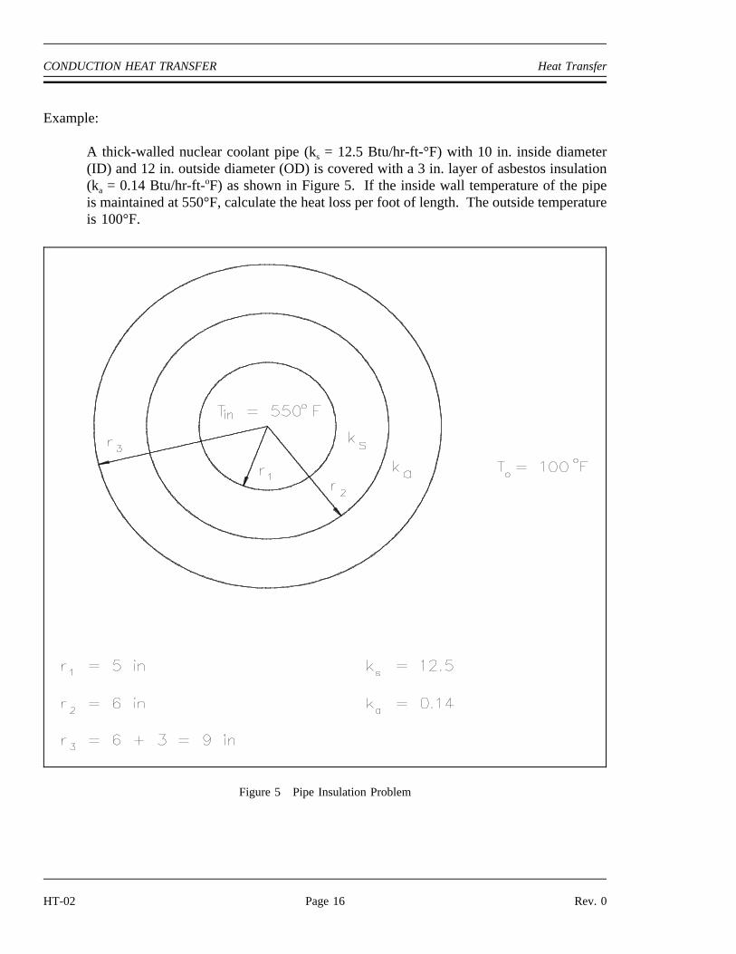
A thick-walled nuclear coolant pipe (ks = 12.5 Btu/hr-ft-°F) with 10 in. inside diameter(ID) and 12 in. outside diameter (OD) is covered with a 3 in. layer of asbestos insulation(ka = 0.14 Btu/hr-ft-oF) as shown in Figure 5. If the inside wall temperature of the pipeis maintained at 550°F, calculate the heat loss per foot of length. The outside temperatureis 100°F.
Figure 5 Pipe Insulation Problem
HT-02 Page 16 Rev. 0

Heat Transfer CONDUCTION HEAT TRANSFER
Solution:
Q̇L
2π (Tin To)
ln
r2
r1
ks
ln
r3
r2
ka
2π (5500F 100oF)
ln
6 in5 in
12.5 Btu
hr ft oF
ln
9 in6 in
0.14 Btu
hr ft oF
971 Btuhr ft
Summary
The important information in this chapter is summarized below.
Conduction Heat Transfer Summary
• Conduction heat transfer is the transfer of thermal energy by interactions betweenadjacent molecules of a material.
• Fourier’s Law of Conduction can be used to solve for rectangular and cylindricalcoordinate problems.
• Heat flux ( ) is the heat transfer rate ( ) divided by the area (A).Q̇ Q̇
• Heat conductance problems can be solved using equivalent resistance formulasanalogous to electrical circuit problems.
Rev. 0 Page 17 HT-02

CONVECTION HEAT TRANSFER Heat Transfer
CONVECTION HEAT TRANSFER
Heat transfer by the motion and mixing of the molecules of a liquid or gas iscalled convection.
EO 1.9 Given the formula for heat transfer and the operatingconditions of the system, CALCULATE the rate of heattransfer by convection.
Convection
Convection involves the transfer of heat by the motion and mixing of "macroscopic" portions ofa fluid (that is, the flow of a fluid past a solid boundary). The term natural convection is usedif this motion and mixing is caused by density variations resulting from temperature differenceswithin the fluid. The term forced convection is used if this motion and mixing is caused by anoutside force, such as a pump. The transfer of heat from a hot water radiator to a room is anexample of heat transfer by natural convection. The transfer of heat from the surface of a heatexchanger to the bulk of a fluid being pumped through the heat exchanger is an example offorced convection.
Heat transfer by convection is more difficult to analyze than heat transfer by conduction becauseno single property of the heat transfer medium, such as thermal conductivity, can be defined todescribe the mechanism. Heat transfer by convection varies from situation to situation (upon thefluid flow conditions), and it is frequently coupled with the mode of fluid flow. In practice,analysis of heat transfer by convection is treated empirically (by direct observation).
Convection heat transfer is treated empirically because of the factors that affect the stagnant filmthickness:
Fluid velocityFluid viscosityHeat fluxSurface roughnessType of flow (single-phase/two-phase)
Convection involves the transfer of heat between a surface at a given temperature (Ts) and fluidat a bulk temperature (Tb). The exact definition of the bulk temperature (Tb) varies dependingon the details of the situation. For flow adjacent to a hot or cold surface, Tb is the temperatureof the fluid "far" from the surface. For boiling or condensation, Tb is the saturation temperatureof the fluid. For flow in a pipe, Tb is the average temperature measured at a particular cross-section of the pipe.
HT-02 Page 18 Rev. 0

Heat Transfer CONVECTION HEAT TRANSFER
The basic relationship for heat transfer by convection has the same form as that for heat transferby conduction:
(2-9)Q̇ h A ∆T
where:
= rate of heat transfer (Btu/hr)Q̇
h = convective heat transfer coefficient (Btu/hr-ft2-°F)
A = surface area for heat transfer (ft2)
∆T = temperature difference (°F)
The convective heat transfer coefficient (h) is dependent upon the physical properties of the fluidand the physical situation. Typically, the convective heat transfer coefficient for laminar flowis relatively low compared to the convective heat transfer coefficient for turbulent flow. This isdue to turbulent flow having a thinner stagnant fluid film layer on the heat transfer surface.Values of h have been measured and tabulated for the commonly encountered fluids and flowsituations occurring during heat transfer by convection.
Example:
A 22 foot uninsulated steam line crosses a room. The outer diameter of the steam lineis 18 in. and the outer surface temperature is 280oF. The convective heat transfercoefficient for the air is 18 Btu/hr-ft2-oF. Calculate the heat transfer rate from the pipeinto the room if the room temperature is 72oF.
Solution:
Q̇ h A ∆T
h (2 π r L) ∆T
18 Btu
hr ft 2 °F2 (3.14) (0.75 ft) (22 ft) (280°F 72°F)
3.88 x 10⁵ Btuhr
Many applications involving convective heat transfer take place within pipes, tubes, or somesimilar cylindrical device. In such circumstances, the surface area of heat transfer normally given
in the convection equation ( ) varies as heat passes through the cylinder. In addition,Q̇ h A ∆Tthe temperature difference existing between the inside and the outside of the pipe, as well as thetemperature differences along the pipe, necessitates the use of some average temperature valuein order to analyze the problem. This average temperature difference is called the log meantemperature difference (LMTD), described earlier.
Rev. 0 Page 19 HT-02

CONVECTION HEAT TRANSFER Heat Transfer
It is the temperature difference at one end of the heat exchanger minus the temperature differenceat the other end of the heat exchanger, divided by the natural logarithm of the ratio of these twotemperature differences. The above definition for LMTD involves two important assumptions:(1) the fluid specific heats do not vary significantly with temperature, and (2) the convection heattransfer coefficients are relatively constant throughout the heat exchanger.
Overall Heat Transfer Coefficient
Many of the heat transfer processes encountered in nuclear facilities involve a combination ofboth conduction and convection. For example, heat transfer in a steam generator involvesconvection from the bulk of the reactor coolant to the steam generator inner tube surface,conduction through the tube wall, and convection from the outer tube surface to the secondaryside fluid.
In cases of combined heat transfer for a heat exchanger, there are two values for h. There is theconvective heat transfer coefficient (h) for the fluid film inside the tubes and a convective heattransfer coefficient for the fluid film outside the tubes. The thermal conductivity (k) andthickness (∆x) of the tube wall must also be accounted for. An additional term (Uo), called theoverall heat transfer coefficient, must be used instead. It is common practice to relate the total
rate of heat transfer ( ) to the cross-sectional area for heat transfer (Ao) and the overall heatQ̇transfer coefficient (Uo). The relationship of the overall heat transfer coefficient to the individualconduction and convection terms is shown in Figure 6.
Figure 6 Overall Heat Transfer Coefficient
HT-02 Page 20 Rev. 0
Heat Transfer CONVECTION HEAT TRANSFER
Recalling Equation 2-3:
Q̇ UoAo∆To
where Uo is defined in Figure 6.
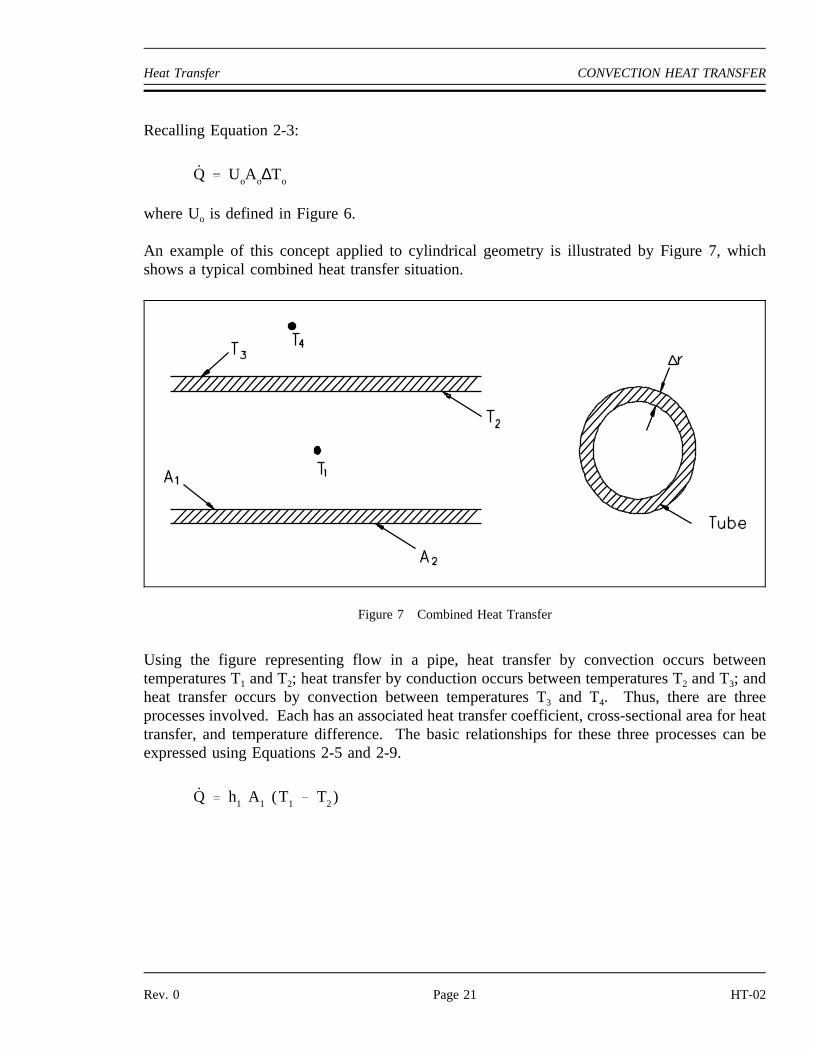
An example of this concept applied to cylindrical geometry is illustrated by Figure 7, whichshows a typical combined heat transfer situation.
Figure 7 Combined Heat Transfer
Using the figure representing flow in a pipe, heat transfer by convection occurs betweentemperatures T1 and T2; heat transfer by conduction occurs between temperatures T2 and T3; andheat transfer occurs by convection between temperatures T3 and T4. Thus, there are threeprocesses involved. Each has an associated heat transfer coefficient, cross-sectional area for heattransfer, and temperature difference. The basic relationships for these three processes can beexpressed using Equations 2-5 and 2-9.
Q̇ h1 A1 (T1 T2)
Rev. 0 Page 21 HT-02

CONVECTION HEAT TRANSFER Heat Transfer
Q̇ k∆r
Alm (T2 T3)
Q̇ h2 A2 (T3 T4)
∆To can be expressed as the sum of the∆T of the three individual processes.
∆To (T1 T2) (T2 T3) (T3 T4)
If the basic relationship for each process is solved for its associated temperature difference andsubstituted into the expression for∆To above, the following relationship results.
∆To Q̇
1h1 A1
∆rk Alm
1h2 A2
This relationship can be modified by selecting a reference cross-sectional area Ao.
∆To
Q̇Ao
Ao
h1 A1
∆r Ao
k Alm
Ao
h2 A2
Solving for results in an equation in the form .Q̇ Q̇ Uo Ao ∆To
Q̇ 1
Ao
h1 A1
∆r Ao
k Alm
Ao
h2 A2
Ao ∆To
where:
(2-10)Uo
1
Ao
h1 A1
∆r Ao
k Alm
Ao
h2 A2
Equation 2-10 for the overall heat transfer coefficient in cylindrical geometry is relativelydifficult to work with. The equation can be simplified without losing much accuracy if the tubethat is being analyzed is thin-walled, that is the tube wall thickness is small compared to the tubediameter. For a thin-walled tube, the inner surface area (A1), outer surface area (A2), and logmean surface area (A1m), are all very close to being equal. Assuming that A1, A2, and A1m areequal to each other and also equal to Ao allows us to cancel out all the area terms in thedenominator of Equation 2-11.
HT-02 Page 22 Rev. 0

Heat Transfer CONVECTION HEAT TRANSFER
This results in a much simpler expression that is similar to the one developed for a flat plate heatexchanger in Figure 6.
(2-11)Uo
11h1
∆rk
1h2
The convection heat transfer process is strongly dependent upon the properties of the fluid beingconsidered. Correspondingly, the convective heat transfer coefficient (h), the overall coefficient(Uo), and the other fluid properties may vary substantially for the fluid if it experiences a largetemperature change during its path through the convective heat transfer device. This is especiallytrue if the fluid’s properties are strongly temperature dependent. Under such circumstances, thetemperature at which the properties are "looked-up" must be some type of average value, ratherthan using either the inlet or outlet temperature value.
For internal flow, the bulk or average value of temperature is obtained analytically through theuse of conservation of energy. For external flow, an average film temperature is normallycalculated, which is an average of the free stream temperature and the solid surface temperature.In any case, an average value of temperature is used to obtain the fluid properties to be used inthe heat transfer problem. The following example shows the use of such principles by solvinga convective heat transfer problem in which the bulk temperature is calculated.
Convection Heat Transfer
Example:
A flat wall is exposed to the environment. The wall is covered with a layer of insulation1 in. thick whose thermal conductivity is 0.8 Btu/hr-ft-°F. The temperature of the wallon the inside of the insulation is 600°F. The wall loses heat to the environment byconvection on the surface of the insulation. The average value of the convection heattransfer coefficient on the insulation surface is 950 Btu/hr-ft2-°F. Compute the bulktemperature of the environment (Tb) if the outer surface of the insulation does not exceed105°F.
Rev. 0 Page 23 HT-02

CONVECTION HEAT TRANSFER Heat Transfer
Solution:
a. Find heat flux ( ) through the insulation.Q̇
Q̇ k A
∆T∆x
Q̇A
0.8 Btuhr ft °F
600°F 105°F
1 in 1 ft12 in
4752 Btu
hr ft 2
b. Find the bulk temperature of the environment.
Q̇ h A (Tins Tb)
(Tins Tb)Q̇
h A
Tb Tins
Q̇h
Tb 105°F
4752 Btu
hr ft 2
950 Btu
hr ft 2 °F
Tb 100°F
HT-02 Page 24 Rev. 0

Heat Transfer CONVECTION HEAT TRANSFER
Summary
The important information in this chapter is summarized below.
Convection Heat Transfer Summary
• Convection heat transfer is the transfer of thermal energy by the mixing andmotion of a fluid or gas.
• Whether convection is natural or forced is determined by how the mediumis placed into motion.
• When both convection and conduction heat transfer occurs, the overall heattransfer coefficient must be used to solve problems.
• The heat transfer equation for convection heat transfer is .Q̇ hA∆T
Rev. 0 Page 25 HT-02

RADIATION HEAT TRANSFER Heat Transfer
RADIANT HEAT TRANSFER
Radiant heat transfer is thermal energy transferred by means of electromagneticwaves or particles.
EO 1.10 DESCRIBE how the following terms relate to radiantheat transfer:a. Black body radiationb. Emissivityc. Radiation configuration factor
Thermal Radiation
Radiant heat transfer involves the transfer of heat by electromagnetic radiation that arises due tothe temperature of a body. Most energy of this type is in the infra-red region of theelectromagnetic spectrum although some of it is in the visible region. The term thermal radiationis frequently used to distinguish this form of electromagnetic radiation from other forms, suchas radio waves, x-rays, or gamma rays. The transfer of heat from a fireplace across a room inthe line of sight is an example of radiant heat transfer.
Radiant heat transfer does not need a medium, such as air or metal, to take place. Any materialthat has a temperature above absolute zero gives off some radiant energy. When a cloud coversthe sun, both its heat and light diminish. This is one of the most familiar examples of heattransfer by thermal radiation.
Black Body Radiation
A body that emits the maximum amount of heat for its absolute temperature is called a blackbody. Radiant heat transfer rate from a black body to its surroundings can be expressed by thefollowing equation.
(2-12)Q̇ σAT 4
where:
= heat transfer rate (Btu/hr)Q̇
σ = Stefan-Boltzman constant (0.174 Btu/hr-ft2-°R4)
A = surface area (ft2)
T = temperature (°R)
HT-02 Page 26 Rev. 0

Heat Transfer RADIATION HEAT TRANSFER
Two black bodies that radiate toward each other have a net heat flux between them. The netflow rate of heat between them is given by an adaptation of Equation 2-12.
Q̇ σA(T 41 T4
2 )
where:
A = surface area of the first body (ft2)
T1 = temperature of the first body (°R)
T2 = temperature of the second body (°R)
All bodies above absolute zero temperature radiate some heat. The sun and earth both radiateheat toward each other. This seems to violate the Second Law of Thermodynamics, which statesthat heat cannot flow from a cold body to a hot body. The paradox is resolved by the fact thateach body must be in direct line of sight of the other to receive radiation from it. Therefore,whenever the cool body is radiating heat to the hot body, the hot body must also be radiatingheat to the cool body. Since the hot body radiates more heat (due to its higher temperature) thanthe cold body, the net flow of heat is from hot to cold, and the second law is still satisfied.
Emissivity
Real objects do not radiate as much heat as a perfect black body. They radiate less heat than ablack body and are called gray bodies. To take into account the fact that real objects are graybodies, Equation 2-12 is modified to be of the following form.
Q̇ εσAT 4
where:
ε = emissivity of the gray body (dimensionless)
Emissivity is simply a factor by which we multiply the black body heat transfer to take intoaccount that the black body is the ideal case. Emissivity is a dimensionless number and has amaximum value of 1.0.
Radiation Configuration Factor
Radiative heat transfer rate between two gray bodies can be calculated by the equation statedbelow.
Q̇ fa fe σA(T 41 T4
2 )
Rev. 0 Page 27 HT-02

RADIATION HEAT TRANSFER Heat Transfer
where:
fa = is the shape factor, which depends on the spatial arrangement of the two objects(dimensionless)
fe = is the emissivity factor, which depends on the emissivities of both objects(dimensionless)
The two separate terms fa and fe can be combined and given the symbol f. The heat flowbetween two gray bodies can now be determined by the following equation:
(2-13)Q̇ fσA(T 41 T4
2 )
The symbol (f) is a dimensionless factor sometimes called theradiation configuration factor,which takes into account the emissivity of both bodies and their relative geometry. The radiationconfiguration factor is usually found in a text book for the given situation. Once theconfiguration factor is obtained, the overall net heat flux can be determined. Radiant heat fluxshould only be included in a problem when it is greater than 20% of the problem.
Example:
Calculate the radiant heat between the floor (15 ft x 15 ft) of a furnace and the roof, ifthe two are located 10 ft apart. The floor and roof temperatures are 2000°F and 600°F,respectively. Assume that the floor and the roof have black surfaces.
Solution:
A1 = A2 = (15 ft) (15 ft) = 225 ft2
T1 = 2000oF + 460 = 2460°R
T2 = 600oF + 460 = 1060°R
Tables from a reference book, or supplied by the instructor, give:
f1-2 = f2-1 = 0.31
Q1-2 = σAf(T14 - T2
4)
= (0.174 Btu
hr ft 2 oR4) (225 ft2) (0.31) [ (2460oR)4 (1060oR)4]
= 4.29 x 10¹⁴ Btu/hr
HT-02 Page 28 Rev. 0

Heat Transfer RADIATION HEAT TRANSFER
Summary
The important information in this chapter is summarized below.
Radiant Heat Transfer Summary
Black body radiation is the maximum amount of heat that can betransferred from an ideal object.
Emissivity is a measure of the departure of a body from the ideal blackbody.
Radiation configuration factor takes into account the emittance andrelative geometry of two objects.
Rev. 0 Page 29 HT-02


![L 18 Thermodynamics [3] Heat transfer Heat transfer convectionconvection conductionconduction radiationradiation emitters of radiationemitters of radiation.](https://static.documents.pub/doc/80x56/5697c0151a28abf838ccdafc/l-18-thermodynamics-3-heat-transfer-heat-transfer-convectionconvection-conductionconduction.jpg)


![L 18 Thermodynamics [3] Review Review Heat transfer processes Heat transfer processes –convection –conduction –radiation Greenhouse effect Greenhouse effect.](https://static.documents.pub/doc/80x56/56649f0c5503460f94c1fbfb/l-18-thermodynamics-3-review-review-heat-transfer-processes-heat-transfer.jpg)


