32
THERMOLIGN ® Products for 3M ™ Aluminum Conductor Composite Reinforced (3M ACCR) July 2015
THERMOLIGN® Products for 3M™ Aluminum Conductor
Composite Reinforced (3M ACCR)
July 2015
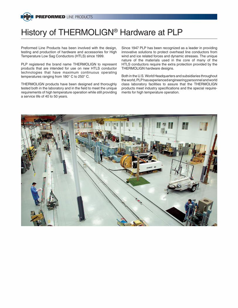
History of THERMOLIGN® Hardware at PLP
Preformed Line Products has been involved with the design, testing and production of hardware and accessories for High Temperature Low Sag Conductors (HTLS) since 1999.
PLP registered the brand name THERMOLIGN to represent products that are intended for use on new HTLS conductor technologies that have maximum continuous operating temperatures ranging from 180° C to 250° C.
THERMOLIGN products have been designed and thoroughly tested both in the laboratory and in the fi eld to meet the unique requirements of high temperature operation while still providing a service life of 40 to 50 years.
Since 1947 PLP has been recognized as a leader in providing innovative solutions to protect overhead line conductors from wind and ice related forces and dynamic stresses. The unique nature of the materials used in the core of many of the HTLS conductors require the extra protection provided by the THERMOLIGN hardware designs.
Both in the U.S. World Headquarters and subsidiaries throughout the world, PLP has experienced engineering personnel and world class laboratory facilities to assure that the THERMOLIGN products meet industry specifi cations and the special require-ments for high temperature operation.

THERMOLIGN® Products for 3M™ Aluminum Conductor Composite Reinforced
Table of Contents
Section 1 – Suspension & Support ProductsTHERMOLIGN® Suspension .................................................................................................................. 1-1
THERMOLIGN® Suspension Fittings ..................................................................................................... 1-2
THERMOLIGN® Suspension: Double .....................................................................................................1-4
THERMOLIGN® Support ........................................................................................................................1-5
Line Guards ............................................................................................................................................. 1-7
Section 2 – Dead-End & Splice ProductsTHERMOLIGN® Dead-End .....................................................................................................................2-9
THERMOLIGN® Splice ..........................................................................................................................2-11
Section 3 – Motion ControlTHERMOLIGN® Twin Spacer ............................................................................................................... 3-13
THERMOLIGN® Spacer Damper .......................................................................................................... 3-14
VORTX™ Vibration Damper .................................................................................................................. 3-16
Section 4 – Repair ProductsArmor Rods for Repair .......................................................................................................................... 4-19
Conductor Splices .................................................................................................................................4-21
Splice/Dead-end Shunt .........................................................................................................................4-22
Section 5 – Installation ProductsTensioning Grip Dead-end ....................................................................................................................5-23
I

THERMOLIGN® Products for 3M™ Aluminum Conductor Composite Reinforced
3M™ is a registered trademark of 3M.II
Designation 267-T16 26/7
300-T16 26/7
336-T16 26/7
427-T13 24/7
397-T23 30/7
477-T13 24/7
477-T16 26/7
557-T16 26/7
605-T13 24/7
636-T10 22/7
kcmil 257 297 340 427 400 480 470 573 591 634
Code Word Partridge Ostrich Linnet Lark Flicker Hawk Dove Peacock Goldfi nch
Diameter (in) 0.630 0.677 0.724 0.800 0.809 0.849 0.852 0.941 0.941 0.962
Product
THERMOLIGN® Suspension TLS- 0094 TLS- 0095 TLS- 0096 TLS- 0099 TLS- 0099 TLS- 0100 TLS- 0100 TLS- 0103 TLS- 0103 TLS- 0104
THERMOLIGN® Suspension, EHV N/A N/A N/A N/A N/A N/A N/A N/A N/A N/A
THERMOLIGN® Susp, Double TLS- 0294 TLS- 0295 TLS- 0296 TLS- 0299 TLS- 0299 TLS- 0300 TLS- 0300 TLS- 0303 TLS- 0303 TLS- 0304
THERMOLIGN® Susp, Double, EHV N/A N/A N/A N/A N/A N/A N/A N/A N/A N/A
THERMOLIGN® Support TLS- 0194 TLS- 0195 TLS- 0196 TLS- 0199 TLS- 0199 TLS- 0200 TLS- 0200 TLS- 0203 TLS- 0203 TLS- 0204
THERMOLIGN® Dead-End TLDE-0097 TLDE-0099 TLS- 0100 TLDE- 0103 TLDE- 0103 TLDE- 0104 TLDE- 0104 TLDE- 0107 TLDE- 0107 TLDE- 0108
THERMOLIGN® Dead-End, EHV N/A N/A N/A N/A N/A N/A N/A N/A N/A N/A
THERMOLIGN® Splice TLSP- 0097 TLSP- 0099 TLSP- 0100 TLSP- 0103 TLSP- 0103 TLSP- 0104 TLSP- 0104 TLSP- 0107 TLSP- 0107 TLSP- 0108
THERMOLIGN® Splice, EHV N/A N/A N/A N/A N/A N/A N/A N/A N/A N/A
VORTX™ Damper (on Susp.) VSD- 2032B VSD- 2032B VSD- 2032B VSD- 2540B VSD- 2540B VSD- 2540B VSD- 2540B VSD- 3540B VSD- 3540B VSD- 3540B
Protector Rods (PR) PR- 0144 PR- 0146 PR- 0148 PR- 0148 PR- 0148 PR- 0150 PR- 0150 PR- 0151 PR- 0151 PR- 0152
Protector Rods (PR), EHV N/A N/A N/A N/A N/A N/A N/A N/A N/A N/A
VORTX™ Damper (on PR) VSD- 2025B VSD- 2025B VSD- 2032B VSD- 2532B VSD- 2532B VSD- 2532B VSD- 2532B VSD- 3540B VSD- 3540B VSD- 3540B
THERMOLIGN® Twin Spacer (18") N/A TLTS- 0101 TLTS- 0102 TLTS- 0104 TLTS- 0104 TLTS- 0105 TLTS- 0105 TLTS- 0107 TLTS- 0107 TLTS- 0108
THERMOLIGN® Twin Spacer (13") N/A TLTS- 0101-13 TLTS- 0102-13 TLTS- 0104-13 TLTS- 0104-13 TLTS- 0105-13 TLTS- 0105-13 TLTS- 0107-13 TLTS- 0107-13 TLTS- 0108-13
THERMOLIGN® Spacer Damper (Tri) N/A TLSDB- 34518 TLSDB- 34519 TLSDB- 34521 TLSDB- 34521 TLSDB- 34522 TLSDB- 34522 TLSDB- 34524 TLSDB- 34524 TLSDB- 34525
THERMOLIGN® Spacer Damper (Quad) N/A TLSDB- 44518 TLSDB- 44519 TLTSB- 44521 TLTSB- 44521 TLSDB- 44522 TLSDB- 44522 TLSDB- 44524 TLSDB- 44524 TLSDB- 44525
Repair Rods (Armor Rods) AR- 0126 AR- 0128 AR- 0130 AR- 0132 AR- 0132 AR- 0134 AR- 0134 AR- 0136 AR- 0136 AR- 0136
Repair Rods (Armor Rods), EHV N/A N/A N/A N/A N/A N/A N/A N/A N/A N/A
Line Guards MG- 0143 MG- 0145 MG- 0147 MG- 0149 MG- 0149 MG- 0150 MG- 0150 MG- 0151 MG- 0151 MG- 0152
Line Guards, EHV N/A N/A N/A N/A N/A N/A N/A N/A N/A N/A
Conductor Splice LS- 0137 LS- 0139 LS- 0140 LS- 0143 LS- 0143 LS- 0144 LS- 0144 LS- 0147 LS- 0147 LS- 0147
Conductor Splice, EHV N/A N/A N/A N/A N/A N/A N/A N/A N/A N/A
Splice/Dead-end Shunt SS- 0008 SS- 0009 SDES- 0001 SDES- 0004 SDES- 0004 SDES- 0005 SDES- 0006 SDES- 0008 SDES- 0008 SDES- 0008
Tensioning Grip TG- 3006 TG- 3009 TG- 3011 TG- 3015 TG- 3015 TG- 3017 TG- 3017 TG- 3020 TG- 3020 TG- 3021

THERMOLIGN® Products for 3M™ Aluminum Conductor Composite Reinforced
3M™ is a registered trademark of 3M. III
Designation 557-T23 30/19
763TW-T17 20/19
795TW-T13 20/19
636-T16 26/19
680-T19 28/19
715-T13 24/7
795-T10 22/7
795-T13 24/19
795-T16 26/19
kcmil 575 763 795 656 680 720 780 824 824
Code Word Eagle Wabash/TW Condor/TW Grosbeak Stilt Puffi n Condor Drake
Diameter (in) 0.970 0.990 0.992 1.006 1.039 1.040 1.067 1.112 1.128
Product
THERMOLIGN® Suspension TLS-0104 TLS-0105 TLS-0105 TLS-0105 TLS-0106 TLS-0106 TLS-0107 TLS-0109 TLS-0109
THERMOLIGN® Suspension, EHV N/A TLS-0105EHV TLS-0105EHV TLS-0105EHV TLS-0106EHV TLS-0106EHV TLS-0107EHV TLS-0109EHV TLS-0109EHV
THERMOLIGN® Susp, Double TLS-0304 TLS-0305 TLS-0305 TLS-0305 TLS-0306 TLS-0306 TLS-0307 TLS-0309 TLS-0309
THERMOLIGN® Susp, Double, EHV N/A TLS-0305EHV TLS-0305EHV TLS-0305EHV TLS-0306EHV TLS-0306EHV TLS-0307EHV TLS-0309EHV TLS-0309EHV
THERMOLIGN® Support TLS-0204 TLS-0205 TLS-0205 TLS-0205 TLS-0206 TLS-0206 TLS-0207 TLS-0209 TLS-0209
THERMOLIGN® Dead-End TLDE-0109 TLDE-0110 TLDE-0110 TLDE-0111 TLDE-0112 TLDE-0112 TLDE-0112 TLDE-0114 TLDE-0114
THERMOLIGN® Dead-End, EHV N/A TLDE-0110EHV TLDE-0110EHV TLDE-0111EHV TLDE-0112EHV TLDE-0112EHV TLDE-0112EHV TLDE-0114EHV TLDE-0114EHV
THERMOLIGN® Splice TLSP-0109 TLSP-0110 TLSP-0110 TLSP-0111 TLSP-0112 TLSP-0112 TLSP-0112 TLSP-0114 TLSP-0114
THERMOLIGN® Splice, EHV N/A TLSP-0110EHV TLSP-0110EHV TLSP-0111EHV TLSP-0112EHV TLSP-0112EHV TLSP-0112EHV TLSP-0114EHV TLSP-0114EHV
VORTX™ Damper (on Susp.) VSD-3540B VSD-4040B VSD-4040B VSD-4040B VSD-4040B VSD-4040B VSD-4040B VSD-4050B VSD-4050B
Protector Rods (PR) PR-0152 PR-0152 PR-0152 PR-0152 PR-0154 PR-0154 PR-0155 PR-0156 PR-0156
Protector Rods (PR), EHV N/A PR-0152E PR-0152E PR-0152E PR-0154E PR-0154E PR-0155E PR-0156E PR-0156E
VORTX™ Damper (on PR) VSD-3540B VSD-4040B VSD-4040B VSD-4040B VSD-4040B VSD-4040B VSD-4040B VSD-4040B VSD-4050B
THERMOLIGN® Twin Spacer (18") TLTS-0108 TLTS-0109 TLTS-0109 TLTS-0109 TLTS-0110 TLTS-0110 TLTS-0110 TLTS-0112 TLTS-0112
THERMOLIGN® Twin Spacer (13") TLTS-0108-13 TLTS-0109-13 TLTS-0109-13 TLTS-0109-13 TLTS-0110-13 TLTS-0110-13 TLTS-0110-13 TLTS-0112-13 TLTS-0112-13
THERMOLIGN® Spacer Damper (Tri) TLSDB-34525 TLSDB-34526 TLSDB-34526 TLSDB-34526 TLSDB-34527 TLSDB-34527 TLSDB-34527 TLSDB-34529 TLSDB-34529
THERMOLIGN® Spacer Damper (Quad) TLSDB-44525 TLSDB-44526 TLSDB-44526 TLSDB-44526 TLSDB-44527 TLSDB-44527 TLSDB-44527 TLSDB-44529 TLSDB-44529
Repair Rods (Armor Rods) AR-0136 AR-0137 AR-0137 AR-0137 AR-0139 AR-0139 AR-0140 AR-0141 AR-0141
Repair Rods (Armor Rods), EHV N/A AR-0500 AR-0500 AR-0500 AR-0502 AR-0502 AR-0503 AR-0504 AR-0504
Line Guards MG-0152 MG-0153 MG-0153 MG-0153 MG-0154 MG-0154 MG-0155 MG-0156 MG-0156
Line Guards, EHV N/A MGMS13889 MGMS13889 MGMS13889 MGMS3517 MGMS3517 N/A MGMS11556 MGMS11556
Conductor Splice LS-0148 LS-0148 LS-0148 LS-0148 LS-0149 LS-0149 LS-0150 LS-0151 LS-0151
Conductor Splice, EHV N/A N/A N/A N/A LSMS7953 LSMS7953 N/A LSMS4854 LSMS4854
Splice/Dead-end Shunt SDES-0009 SDES-0009 SDES-0009 SDES-0009 SDES-0010 SDES-0010 SDES-0011 SDES-0012 SDES-0012
Tensioning Grip TG-3021 TG-3022 TG-3022 TG-3022 TG-3024 TG-3024 TG-3025 TG-3027 TG-3027
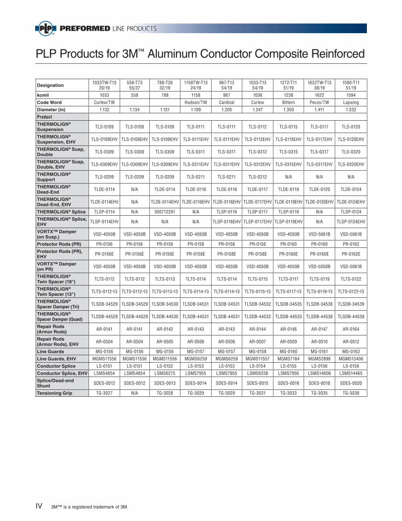
PLP Products for 3M™ Aluminum Conductor Composite Reinforced
3M™ is a registered trademark of 3M.
Designation 1033TW-T13 20/19
558-T73 55/37
788-T26 32/19
1158TW-T13 24/19
967-T13 54/19
1033-T13 54/19
1272-T11 51/19
1622TW-T13 38/19
1590-T11 51/19
kcmil 1033 558 788 1158 967 1036 1238 1622 1594
Code Word Curlew/TW Hudson/TW Cardinal Curlew Bittern Pecos/TW Lapwing
Diameter (in) 1.132 1.134 1.151 1.199 1.205 1.247 1.350 1.411 1.532
Product
THERMOLIGN® Suspension TLS-0109 TLS-0109 TLS-0109 TLS-0111 TLS-0111 TLS-0112 TLS-0115 TLS-0117 TLS-0120
THERMOLIGN® Suspension, EHV TLS-0109EHV TLS-0109EHV TLS-0109EHV TLS-0111EHV TLS-0111EHV TLS-0112EHV TLS-0115EHV TLS-0117EHV TLS-0120EHV
THERMOLIGN® Susp, Double TLS-0309 TLS-0309 TLS-0309 TLS-0311 TLS-0311 TLS-0312 TLS-0315 TLS-0317 TLS-0320
THERMOLIGN® Susp, Double, EHV TLS-0309EHV TLS-0309EHV TLS-0309EHV TLS-0311EHV TLS-0311EHV TLS-0312EHV TLS-0315EHV TLS-0317EHV TLS-0320EHV
THERMOLIGN® Support TLS-0209 TLS-0209 TLS-0209 TLS-0211 TLS-0211 TLS-0212 N/A N/A N/A
THERMOLIGN® Dead-End TLDE-0114 N/A TLDE-0114 TLDE-0116 TLDE-0116 TLDE-0117 TLDE-0119 TLDE-0120 TLDE-0124
THERMOLIGN® Dead-End, EHV TLDE-0114EHV N/A TLDE-0114EHV TLDE-0116EHV TLDE-0116EHV TLDE-0117EHV TLDE-0119EHV TLDE-0120EHV TLDE-0124EHV
THERMOLIGN® Splice TLSP-0114 N/A 300712291 N/A TLSP-0116 TLSP-0117 TLSP-0119 N/A TLSP-0124
THERMOLIGN® Splice, EHV TLSP-0114EHV N/A N/A N/A TLSP-0116EHV TLSP-0117EHV TLSP-0119EHV N/A TLSP-0124EHV
VORTX™ Damper (on Susp.) VSD-4050B VSD-4050B VSD-4050B VSD-4050B VSD-4050B VSD-4050B VSD-4050B VSD-5061B VSD-5061B
Protector Rods (PR) PR-0156 PR-0156 PR-0156 PR-0158 PR-0158 PR-0158 PR-0160 PR-0160 PR-0162
Protector Rods (PR), EHV PR-0156E PR-0156E PR-0156E PR-0158E PR-0158E PR-0158E PR-0160E PR-0160E PR-0162E
VORTX™ Damper (on PR) VSD-4050B VSD-4050B VSD-4050B VSD-4050B VSD-4050B VSD-4050B VSD-4050B VSD-5050B VSD-5061B
THERMOLIGN® Twin Spacer (18") TLTS-0112 TLTS-0112 TLTS-0113 TLTS-0114 TLTS-0114 TLTS-0115 TLTS-0117 TLTS-0119 TLTS-0122
THERMOLIGN® Twin Spacer (13") TLTS-0112-13 TLTS-0112-13 TLTS-0113-13 TLTS-0114-13 TLTS-0114-13 TLTS-0115-13 TLTS-0117-13 TLTS-0119-13 TLTS-0122-13
THERMOLIGN® Spacer Damper (Tri) TLSDB-34529 TLSDB-34529 TLSDB-34530 TLSDB-34531 TLSDB-34531 TLSDB-34532 TLSDB-34535 TLSDB-34536 TLSDB-34539
THERMOLIGN® Spacer Damper (Quad) TLSDB-44529 TLSDB-44529 TLSDB-44530 TLSDB-44531 TLSDB-44531 TLSDB-44532 TLSDB-44535 TLSDB-44536 TLSDB-44539
Repair Rods (Armor Rods) AR-0141 AR-0141 AR-0142 AR-0143 AR-0143 AR-0144 AR-0146 AR-0147 AR-0164
Repair Rods (Armor Rods), EHV AR-0504 AR-0504 AR-0505 AR-0506 AR-0506 AR-0507 AR-0509 AR-0510 AR-0512
Line Guards MG-0156 MG-0156 MG-0156 MG-0157 MG-0157 MG-0158 MG-0160 MG-0161 MG-0163
Line Guards, EHV MGMS11556 MGMS11556 MGMS11556 MGMS6259 MGMS6259 MGMS11557 MGMS7184 MGMS2898 MGMS13406
Conductor Splice LS-0151 LS-0151 LS-0152 LS-0153 LS-0153 LS-0154 LS-0155 LS-0156 LS-0159
Conductor Splice, EHV LSMS4854 LSMS4854 LSMS6275 LSMS7955 LSMS7955 LSMS8338 LSMS7956 LSMS14606 LSMS14465
Splice/Dead-end Shunt SDES-0012 SDES-0012 SDES-0013 SDES-0014 SDES-0014 SDES-0015 SDES-0016 SDES-0018 SDES-0020
Tensioning Grip TG-3027 N/A TG-3028 TG-3029 TG-3029 TG-3031 TG-3033 TG-3035 TG-3038
IV
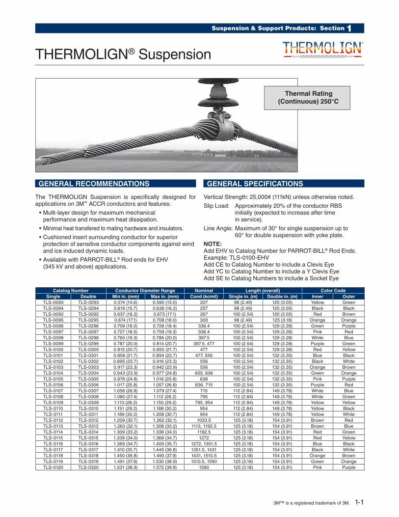
Suspension & Support Products: Section 1
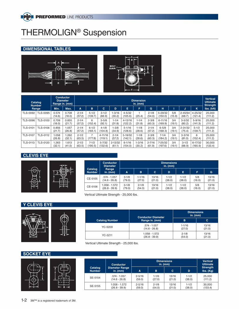
THERMOLIGN® Suspension
GENERAL RECOMMENDATIONS
The THERMOLIGN Suspension is specifically designed for applications on 3M™ ACCR conductors and features:
• Multi-layer design for maximum mechanical performance and maximum heat dissipation.
• Minimal heat transfered to mating hardware and insulators.
• Cushioned insert surrounding conductor for superior protection of sensitive conductor components against wind and ice induced dynamic loads.
• Available with PARROT-BILL® Rod ends for EHV (345 kV and above) applications.
GENERAL SPECIFICATIONS
Vertical Strength: 25,000# (111kN) unless otherwise noted.
Slip Load: Approximately 20% of the conductor RBS initially (expected to increase after time in service).
Line Angle: Maximum of 30° for single suspension up to 60° for double suspension with yoke plate.
NOTE: Add EHV to Catalog Number for PARROT-BILL® Rod Ends. Example: TLS-0100-EHVAdd CE to Catalog Number to include a Clevis EyeAdd YC to Catalog Number to include a Y Clevis EyeAdd SE to Catalog Numbers to include a Socket Eye
Catalog Number Conductor Diameter Range Nominal Length (overall) Color CodeSingle Double Min in. (mm) Max in. (mm) Cond (kcmil) Single in. (m) Double in. (m) Inner Outer
TLS-0093 TLS-0293 0.574 (14.6) 0.590 (15.0) 207 98 (2.49) 120 (3.05) Yellow GreenTLS-0094 TLS-0294 0.619 (15.7) 0.636 (16.2) 257 98 (2.49) 120 (3.05) Black BlackTLS-0092 TLS-0292 0.637 (16.2) 0.673 (17.1) 267 100 (2.54) 120 (3.05) Red BrownTLS-0095 TLS-0295 0.674 (17.1) 0.708 (18.0) 300 98 (2.49) 125 (3.18) Orange OrangeTLS-0096 TLS-0296 0.709 (18.0) 0.726 (18.4) 336.4 100 (2.54) 129 (3.28) Green PurpleTLS-0097 TLS-0297 0.727 (18.5) 0.759 (19.3) 336.4 100 (2.54) 129 (3.28) Pink RedTLS-0098 TLS-0298 0.760 (19.3) 0.786 (20.0) 397.5 100 (2.54) 129 (3.28) White BlueTLS-0099 TLS-0299 0.787 (20.0) 0.814 (20.7) 397.5, 477 100 (2.54) 129 (3.28) Purple GreenTLS-0100 TLS-0300 0.815 (20.7) 0.855 (21.7) 477 100 (2.54) 129 (3.28) Red YellowTLS-0101 TLS-0301 0.856 (21.7) 0.894 (22.7) 477, 556 100 (2.54) 132 (3.35) Blue BlackTLS-0102 TLS-0302 0.895 (22.7) 0.916 (23.3) 556 100 (2.54) 132 (3.35) Black WhiteTLS-0103 TLS-0303 0.917 (23.3) 0.942 (23.9) 556 100 (2.54) 132 (3.35) Orange BrownTLS-0104 TLS-0304 0.943 (23.9) 0.977 (24.8) 605, 636 100 (2.54) 132 (3.35) Green OrangeTLS-0105 TLS-0305 0.978 (24.8) 1.016 (25.8) 636 100 (2.54) 132 (3.35) Pink PurpleTLS-0106 TLS-0306 1.017 (25.8) 1.057 (26.8) 636, 715 100 (2.54) 132 (3.35) Purple RedTLS-0107 TLS-0307 1.058 (26.8) 1.079 (27.4) 715 112 (2.84) 149 (3.78) White BlueTLS-0108 TLS-0308 1.080 (27.4) 1.112 (28.2) 795 112 (2.84) 149 (3.78) White GreenTLS-0109 TLS-0309 1.113 (28.2) 1.150 (29.2) 795, 954 112 (2.84) 149 (3.78) Yellow YellowTLS-0110 TLS-0310 1.151 (29.2) 1.188 (30.2) 954 112 (2.84) 149 (3.78) Yellow BlackTLS-0111 TLS-0311 1.189 (30.2) 1.208 (30.7) 954 112 (2.84) 149 (3.78) Yellow WhiteTLS-0112 TLS-0312 1.209 (30.7) 1.262 (32.1) 1033.5 125 (3.18) 154 (3.91) Brown RedTLS-0113 TLS-0313 1.263 (32.1) 1.308 (33.2) 1113, 1192.5 125 (3.18) 154 (3.91) Brown BlueTLS-0114 TLS-0314 1.309 (33.2) 1.338 (34.0) 1192.5 125 (3.18) 154 (3.91) Red GreenTLS-0115 TLS-0315 1.339 (34.0) 1.368 (34.7) 1272 125 (3.18) 154 (3.91) Red YellowTLS-0116 TLS-0316 1.369 (34.7) 1.409 (35.7) 1272, 1351.5 125 (3.18) 154 (3.91) Blue BlackTLS-0117 TLS-0317 1.410 (35.7) 1.449 (36.8) 1351.5, 1431 125 (3.18) 154 (3.91) Black WhiteTLS-0118 TLS-0318 1.450 (36.8) 1.490 (37.9) 1431, 1510.5 125 (3.18) 154 (3.91) Orange BrownTLS-0119 TLS-0319 1.491 (37.9) 1.530 (38.9) 1510.5, 1590 125 (3.18) 154 (3.91) Green OrangeTLS-0120 TLS-0320 1.531 (38.9) 1.572 (39.9) 1590 125 (3.18) 154 (3.91) Pink Purple
Thermal Rating (Continuous) 250°C
3M™ is a registered trademark of 3M. 1-1
THERMOLIGN® Suspension
DIMENSIONAL TABLES
Catalog NumberRange
Conductor Diameter
Range in. (mm)Dimension
in. (mm)
Vertical Ultimate Strength lbs. (kN)Min. Max. A B C D E F G H I J K
TLS-0092 TLS-0095 0.574 (14.6)
0.708 (18.0)
2-1/4 (57.2)
5-1/2 (139.7)
3-1/2 (88.9)
1-3/16 (30.2)
4-5/32 (105.6)
1 (25.4)
2-1/8 (54.0)
5-29/32 (150.0)
5/8 (15.9)
2-45/64 (68.7)
4-25/32 (121.4)
25,000 (111.2)
TLS-0096 TLS-0100 0.709 (18.0)
0.855 (21.7)
2-1/4 (57.2)
6 (152.4)
3-5/8 (92.1)
1-1/4 (31.8)
4-13/16 (122.2)
1-1/4 (31.8)
2-3/8 (60.3)
6-11/16 (169.9)
3/4 (19.1)
3-5/32 (80.2)
5-9/16 (141.3)
25,000 (111.2)
TLS-0101 TLS-0106 0.856 (21.7)
1.057 (26.8)
2-1/4 (57.2)
6-1/2 (165.1)
4-1/8 (104.8)
1-3/8 (34.9)
5-1/16 (128.6)
1-1/8 (28.6)
2-1/4 (57.2)
6-5/8 (168.3)
3/4 (19.1)
2-31/32 (75.4)
5-1/2 (139.7)
25,000 (111.2)
TLS-0107 TLS-0112 1.058 (26.8)
1.262 (32.1)
2-1/2 (63.5)
7 (177.8)
4-11/16 (119.1)
2-1/4 (57.2)
5-19/32 (142.1)
1-1/8 (28.6)
2-3/8 (60.3)
7-1/4 (184.2)
3/4 (19.1)
3-3/16 (81.0)
6 (152.4)
25,000 (111.2)
TLS-0113 TLS-0120 1.263 (32.1)
1.613 (41.0)
2-1/2 (63.5)
7-1/2 (190.5)
5-7/32 (132.6)
2-13/32 (61.1)
6-1/16 (154.0)
1-3/16 (30.2)
2-7/16 (61.9)
7-25/32 (197.6)
3/4 (19.1)
3-1/2 (88.9)
6-17/32 (165.9)
30,000 (133.4)
CLEVIS EYE
Y CLEVIS EYE
SOCKET EYE
Catalog NumberConductor Diameter
Range in. (mm)
Dimensions in. (mm)
B C
YC-5209 .574 - 1.057(14.6 - 26.8)
1-1/16 (27.0)
13/16 (21.0)
YC-5211 1.058 - 1.572 (26.8 - 39.9)
2-1/8 (54.0)
13/16 (21.0)
Vertical Ultimate Strength - 25,000 lbs.
Catalog Number
Conductor Diameter
Range in. (mm)
Dimensionsin. (mm)
A B C D E F G
CE-5105 .574 - 1.057(14.6 - 26.8)
3-1/8(79.0)
1-1/16(27.0)
13/16(21.0)
1-1/2(38.0)
1-1/2(38.0)
5/8(16.0)
13/16(21.0)
CE-5106 1.058 - 1.572(26.8 - 39.9)
3-1/8(79.0)
2-1/8(54.0)
13/16(21.0)
1-1/2(38.0)
1-1/2(38.0)
5/8(16.0)
13/16(21.0)
Vertical Ultimate Strength - 25,000 lbs.
Catalog Number
Conductor Diameter Range
in. (mm)
Dimensionsin. (mm)
Vertical Ultimate Strength lbs. (Kg)A B C D
SE-5154 .574 - 1.057(14.6 - 26.8)
2-5/16(59.0)
1-1/6(27.0)
13/16(21.0)
1-1/2(38.0)
25,000 (111.2)
SE-5155 1.058 - 1.572(26.8 - 39.9)
2-5/16(59.0)
2-1/8(54.0)
13/16(21.0)
1-1/2(38.0)
30,000 (133.4)
1-2 3M™ is a registered trademark of 3M.
Suspension & Support Products: Section 1
THERMOLIGN® Suspension
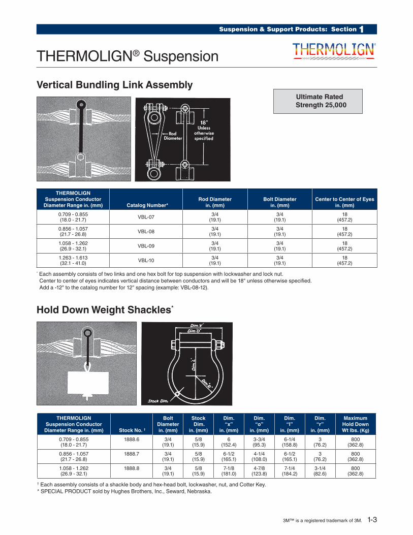
Vertical Bundling Link Assembly
Hold Down Weight Shackles*
THERMOLIGN Suspension Conductor
Diameter Range in. (mm) Catalog Number*Rod Diameter
in. (mm)Bolt Diameter
in. (mm)Center to Center of Eyes
in. (mm)
0.709 - 0.855 (18.0 - 21.7) VBL-07 3/4
(19.1)3/4
(19.1)18
(457.2)
0.856 - 1.057 (21.7 - 26.8) VBL-08 3/4
(19.1)3/4
(19.1)18
(457.2)
1.058 - 1.262 (26.9 - 32.1) VBL-09 3/4
(19.1)3/4
(19.1)18
(457.2)
1.263 - 1.613 (32.1 - 41.0) VBL-10 3/4
(19.1)3/4
(19.1)18
(457.2)
* Each assembly consists of two links and one hex bolt for top suspension with lockwasher and lock nut. Center to center of eyes indicates vertical distance between conductors and will be 18" unless otherwise specified. Add a -12" to the catalog number for 12" spacing (example: VBL-08-12).
THERMOLIGN Suspension Conductor
Diameter Range in. (mm) Stock No. †
Bolt Diameter in. (mm)
Stock Dim.
in. (mm)
Dim.“x”
in. (mm)
Dim.“o”
in. (mm)
Dim.“l”
in. (mm)
Dim.“r”
in. (mm)
Maximum Hold Down Wt lbs. (Kg)
0.709 - 0.855 (18.0 - 21.7)
1888.6 3/4 (19.1)
5/8 (15.9)
6 (152.4)
3-3/4 (95.3)
6-1/4 (158.8)
3 (76.2)
800 (362.8)
0.856 - 1.057 (21.7 - 26.8)
1888.7 3/4 (19.1)
5/8 (15.9)
6-1/2 (165.1)
4-1/4 (108.0)
6-1/2 (165.1)
3 (76.2)
800 (362.8)
1.058 - 1.262 (26.9 - 32.1)
1888.8 3/4 (19.1)
5/8 (15.9)
7-1/8 (181.0)
4-7/8 (123.8)
7-1/4 (184.2)
3-1/4 (82.6)
800 (362.8)
† Each assembly consists of a shackle body and hex-head bolt, lockwasher, nut, and Cotter Key.* SPECIAL PRODUCT sold by Hughes Brothers, Inc., Seward, Nebraska.
Ultimate Rated Strength 25,000
3M™ is a registered trademark of 3M. 1-3

DIMENSIONAL TABLES
Catalog Number Range
Conductor Diameter RangeDimensions
in. (mm) Vertical Ultimate Strength lbs. (kN)Min in. (mm) Max in. (mm) J K L
TLS-0293 – TLS-0295 0.574 (14.6)
0.708 (18.0)
2-45/64 (68.7)
4-25/32 (121.4)
26 (660.4)
50,000 (222.4)
TLS-0296 – TLS-0300 0.709 (18.0)
0.855 (21.7)
3-5/32 (80.2)
5-9/16 (141.3)
29 (736.6)
50,000 (222.4)
TLS-0301 – TLS-0306 0.856 (21.7)
1.057 (26.8)
2-31/32 (75.4)
5-1/2 (139.7)
32 (812.8)
50,000 (222.4)
TLS-0307 – TLS 0312 1.058 (26.8)
1.262 (32.1)
3-3/16 (81.0)
6 (152.4)
37 (939.8)
50,000 (222.4)
TLS-0313 – TLS-0320 1.263 (32.1)
1.572 (39.9)
3-1/2 (88.9)
6-17/32 (165.9)
42 (1066.8)
60,000 (266.9)
EXPLANATORY NOTES:(1) THERMOLIGN® Rod Length and diameter for individual sizes can be taken from catalog number table.(2) Additional dimensional information of the THERMOLIGN Housing is tabulated on Dimensional Tables preceding the THERMOLIGN Suspension: Double section.
THERMOLIGN® Suspension: Double
AGS Yoke Plate
Catalog Number
Dimensions in. (mm) Plate Thickness
in. (mm)
Ultimate Strength lbs. (kN)L H D R A F
YP-5907 12 (304.8)
4 (101.6)
13/16 (20.6)
13/16 (20.6)
1 (25.4) NONE 1/2
(12.7)30,000 (133.4)
YP-5908 18 (457.2)
6-1/4 (158.8)
1 (25.4)
15/16 (23.8)
1-1/4 (31.8)
3-1/2 (88.9)
5/8 (15.9)
40,000 (177.9)
YP-5909 22 (558.8)
7-1/4 (184.2)
1 (25.4)
15/16 (23.8)
1-1/4 (31.8)
4-3/16 (106.4)
5/8 (15.9)
40,000 (177.9)
YP-5910 26 (660.4)
8-1/2 (215.9)
1 (25.4)
15/16 (23.8)
1-1/4 (31.8)
4-15/16 (125.4)
3/4 (19.1)
50,000 (222.4)
YP-5911 29 (736.6)
9-1/2 (241.3)
1 (25.4)
15/16 (23.8)
1-1/4 (31.8)
5-1/2 (139.7)
3/4 (19.1)
50,000 (222.4)
YP-5912 32 (812.8)
10-1/2 (266.7)
1 (25.4)
15/16 (23.8)
1-1/4 (31.8)
6-1/8 (155.6)
3/4 (19.1)
50,000 (222.4)
YP-5913 37 (939.8)
11-3/4 (298.5)
1 (25.4)
15/16 (23.8)
1-1/4 (31.8)
7-1/16 (179.4)
3/4 (19.1)
50,000 (222.4)
Contact PLP or 3M for additional information concerning the correct Yoke Plate selection.
1-4 3M™ is a registered trademark of 3M.

Suspension & Support Products: Section 1THERMOLIGN (TM) Support AssemblyCatalog Number - TLS-0210
C
E
A
B
D Boltlength F
L
StructuralReinforcing
Rods
Outer SupportRods
HardwareAssembly
H
G
2 31
Thermal Rating (Continuous) 250°C
GENERAL RECOMMENDATIONS
The THERMOLIGN Support is specifically designed for trunnion applications on 3M™ ACCR conductors and features:
• Multi-layer design for maximum mechanical performance and maximum heat dissipation.
• Minimal heat transferred to mating hardware and insulators.
• Cushioned insert surrounding conductor for superior protection of sensitive conductor components against wind and ice induced dynamic loads.
GENERAL SPECIFICATIONS
Vertical Strength: 5,000# (22kN) in any direction.
Slip Load: Approximately 20% of the conductor RBS.
Line Angle: Maximum of 30° for single support.
Catalog Number
Diameter Range Length in. (m) (overall)
Color Code
Min in. (mm) Max in. (mm) Inner Outer
TLS-0194 0.634 (16.2) 0.673 (17.1) 98 (2.5) Black Black
TLS-0195 0.674 (17.1) 0.708 (18.0) 98 (2.5) Orange Orange
TLS-0196 0.709 (18.0) 0.726 (18.4) 100 (2.5) Green Purple
TLS-0197 0.727 (18.5) 0.759 (19.3) 100 (2.5) Pink Red
TLS-0198 0.760 (19.3) 0.786 (20.0) 100 (2.5) White Blue
TLS-0199 0.787 (20.0) 0.814 (20.7) 100 (2.5) Purple Green
TLS-0200 0.815 (20.7) 0.855 (21.7) 100 (2.5) Red Yellow
TLS-0201 0.856 (21.7) 0.894 (22.7) 100 (2.5) Blue Black
TLS-0202 0.895 (22.7) 0.916 (23.3) 100 (2.5) Black White
TLS-0203 0.917 (23.3) 0.942 (23.9) 100 (2.5) Orange Brown
TLS-0204 0.943 (23.9) 0.977 (24.8) 100 (2.5) Green Orange
TLS-0205 0.978 (24.8) 1.016 (25.8) 100 (2.5) Pink Purple
TLS-0206 1.017 (25.8) 1.057 (26.8) 100 (2.5) Purple Red
TLS-0207 1.058 (26.8) 1.079 (27.4) 112 (2.8) White Blue
TLS-0208 1.080 (27.4) 1.112 (28.2) 112 (2.8) White Green
TLS-0209 1.113 (28.2) 1.150 (29.2) 112 (2.8) Yellow Yellow
TLS-0210 1.151 (29.2) 1.188 (30.2) 112 (2.8) Yellow Black
TLS-0211 1.189 (30.2) 1.208 (30.7) 112 (2.8) Yellow White
TLS-0212 1.209 (30.7) 1.262 (32.1) 125 (3.2) Brown Red
THERMOLIGN® Support
3M™ is a registered trademark of 3M. 1-5

CLAMP TOP TRUNNION
To insure proper fi t and service life, it is rec om mend ed that only line post insulators with clamp top trunnion caps that conform to ANSI standards be used. See the il lus tra tion on the right for nominal cap dimensions that illustrate ANSI standards that have been es tab lished out lin ing the per mis si ble dimensions and tol er anc es for trunnion caps. Consult the insulator man u fac tur er when in doubt about insulator standards.
The above dimensions are approximates for design information. Consult ANSI specifi cation C29.7-1977 for exact dimensions.
DIMENSIONAL DATA
Conductor Diameter Ranges
in. (mm)
Dimensions in. (mm)
A B C D E F G H
.637-.708 (16.2 - 18.0)
5-1/2 (139.7)
1-5/16 (33.3)
13/16 (20.6)
4-3/16 (106.4)
19/32 (15.1)
2-1/4 (57.2)
3/4 (19.1)
3-7/8 (98.4)
.709-.855 (18.0 - 21.7)
6 (152.4)
1-1/2 (38.1)
13/16 (20.6)
4-5/8 (117.5)
19/32 (15.1)
2-1/4 (57.2)
3/4 (19.1)
3-7/8 (98.4)
.856-1.057 (21.7 - 26.8)
6-1/2 (165.1)
1-5/8 (41.3)
29/32 (23.0)
5-7/64 (129.8)
19/32 (15.1)
2-1/4 (57.2)
3/4 (19.1)
3-7/8 (98.4)
1.058-1.208 (26.8 - 30.7)
7 (177.8)
1-15/16 (49.2)
49/64 (19.4)
5-13/32 (137.3)
19/32 (15.1)
2-1/4 (57.2)
3/4 (19.1)
3-7/8 (98.4)
THERMOLIGN (TM) Support AssemblyCatalog Number - TLS-0210
C
E
A
B
D Boltlength F
L
StructuralReinforcing
Rods
Outer SupportRods
HardwareAssembly
H
G
2 31
THERMOLIGN® Support
1-6 3M™ is a registered trademark of 3M.

Suspension & Support Products: Section 1
Line Guards
GENERAL RECOMMENDATIONS
Line Guards are used with high temperature bolted suspension clamps for jumper loop supports associated with dead-end structures. Line Guards with PARROT-BILL® rod ends are available for applications at 345kV and above.
Catalog NumberConductor Diameter
Range
Length in. (m)
Rod Diameter in. (mm)
Rods Per Set Color Code
UnitsWt.
lbs. (Kg)
StandardEHV
(345kV & above)Min
in. (mm)Max
in. (mm) Per Carton
MG-0143 N/A 0.607 (15.4) 0.63 (16.0) 33 (0.83) 0.146 (3.7) 14 White 50 42 (19.0)
MG-0145 N/A 0.656 (16.7) 0.679 (17.2) 35 (0.89) 0.146 (3.7) 15 Brown 50 48 (21.8)
MG-0147 N/A 0.704 (17.9) 0.74 (18.8) 37 (0.93) 0.146 (3.7) 16 Green 50 54 (24.5)
MG-0149 N/A 0.793 (20.1) 0.84 (21.3) 41 (1.04) 0.146 (3.7) 18 Purple 50 64 (29.0)
MG-0150 N/A 0.841 (21.4) 0.898 (22.8) 43 (1.09) 0.146 (3.7) 19 Blue 25 36 (16.3)
MG-0151 N/A 0.899 (22.8) 0.954 (24.2) 45 (1.14) 0.167 (4.2) 18 Green 25 46 (20.9)
MG-0152 N/A 0.955 (24.3) 0.986 (25.0) 47 (1.19) 0.182 (4.6) 17 White 25 54 (24.5)
MG-0153 MGMS13889 0.987 (25.1) 1.016 (25.8) 49 (1.24) 0.182 (4.6) 18 Yellow 25 58 (26.3)
MG-0154 MGMS3517 1.017 (25.8) 1.064 (27.0) 49 (1.24) 0.182 (4.6) 18 Brown 25 60 (27.2)
MG-0155 N/A 1.065 (27.1) 1.098 (27.9) 51 (1.30) 0.204 (5.2) 17 Green 15 44 (20.0)
MG-0156 MGMS11556 1.099 (27.9) 1.153 (29.3) 53 (1.35) 0.25 (6.4) 15 Orange 15 58 (26.3)
MG-0157 MGMS6259 1.154 (29.3) 1.208 (30.7) 51 (1.30) 0.25 (6.4) 15 Purple 15 62 (28.1)
MG-0158 MGMS11557 1.209 (30.7) 1.268 (32.2) 53 (1.35) 0.25 (6.4) 16 Black 15 68 (30.8)
MG-0160 MGMS7184 1.328 (33.7) 1.39 (35.3) 55 (1.40) 0.25 (6.4) 17 Yellow 10 50 (22.7)
MG-0161 MGMS2898 1.391 (35.3) 1.44 (36.6) 57 (1.44) 0.31 (7.9) 15 Brown 5 36 (16.3)
MG-0163 MGMS13406 1.509 (38.3) 1.578 (40.1) 60 (1.52) 0.31 (7.9) 16 Green 5 41 (18.6)
Single Support and Double Support Length: Identified by “S” and “D” appearing in the length column on the catalog page. Should the maximum distance between tied supports exceed 12 inches, consult the Factory.
Rod Diameter: Added to conductor O.D., assists in arriving at applied overall diameter.
Rods Per Set: Indicates the proper number of rods for each application.
Center Mark: Establishes recommended alignment of rods during application.
NOMENCLATURE
Color Code and Length: Assists in identification of conductor size, correspond-ing to tabular information appearing on catalog page.
Identification Tape: Shows catalog number, nominal sizes.
3M™ is a registered trademark of 3M. 1-7
1-8 3M™ is a registered trademark of 3M.
Dead-End & Splice Products: Section 2
THERMOLIGN® Dead-End
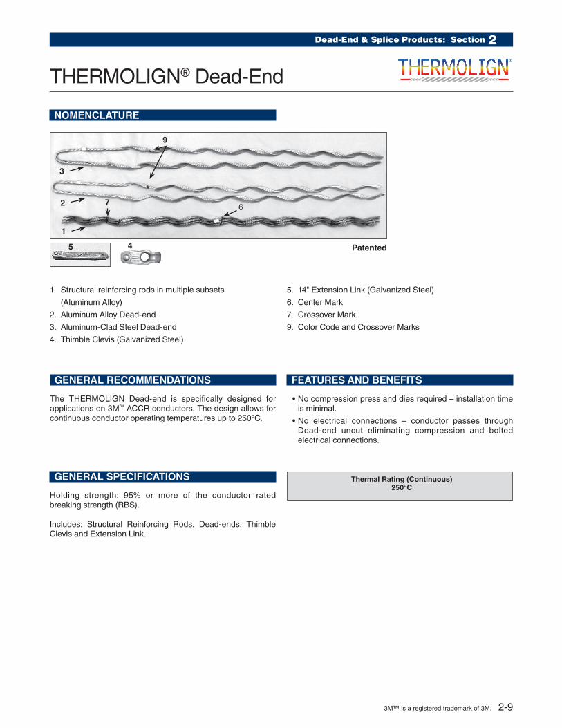
NOMENCLATURE
GENERAL RECOMMENDATIONS
The THERMOLIGN Dead-end is specifi cally designed for applications on 3M™ ACCR conductors. The design allows for continuous conductor operating temperatures up to 250°C.
1. Structural reinforcing rods in multiple subsets
(Aluminum Alloy)
2. Aluminum Alloy Dead-end
3. Aluminum-Clad Steel Dead-end
4. Thimble Clevis (Galvanized Steel)
5. 14" Extension Link (Galvanized Steel)
6. Center Mark
7. Crossover Mark
9. Color Code and Crossover Marks
5
1
2
3
67
9
GENERAL SPECIFICATIONS
Holding strength: 95% or more of the conductor rated breaking strength (RBS).
Includes: Structural Reinforcing Rods, Dead-ends, Thimble Clevis and Extension Link.
FEATURES AND BENEFITS
• No compression press and dies required – installation time is minimal.
• No electrical connections – conductor passes through Dead-end uncut eliminating compression and bolted electrical connections.
Patented
Thermal Rating (Continuous)250°C
4
3M™ is a registered trademark of 3M. 2-9

THERMOLIGN® Dead-End
Catalog Number
Conductor Diameter Range Length in. (m)
Color Codes
Extension Link
Part Number
Thimble Clevis
Part NumberMin
in. (mm)Max
in. (mm)Structural
Rods Dead-ends
TLDE-0100 0.720 (18.3) 0.720 (18.3) 128 (3.25) 89 (2.26) Blue
000601325 00065486
TLDE-0101 0.741 (18.8) 0.752 (19.1) 131 (3.37) 91 (2.31) Brown
TLDE-0102 0.772 (19.6) 0.783 (19.3) 134 (3.40) 93 (2.36) Pink
TLDE-0103 0.806 (20.5) 0.823 (20.9) 138 (3.50) 95 (2.41) Green
TLDE-0104 0.846 (21.5) 0.860 (21.8) 141 (3.58) 97 (2.46) Red
TLDE-0105 0.883 (22.4) 0.900 (22.9) 144 (3.65) 99 (2.51) Purple
TLDE-0106 0.901 (22.9) 0.914 (23.2) 158 (4.01) 109 (2.76) Yellow
TLDE-0107 0.927 (23.5) 0.930 (23.6) 161 (4.08) 111 (2.81) Orange
TLDE-0108 0.953 (24.2) 0.962 (24.2) 162 (4.11) 111 (2.81) Black
TLDE-0109 0.963 (24.5) 0.977 (24.8) 163 (4.14) 112 (2.84) Blue
TLDE-0110 0.990 (25.1) 0.994 (25.2) 166 (4.21) 114 (2.89) Brown
TLDE-0111 1.000 (25.4) 1.019 (25.9) 168 (4.26) 115 (2.92) Pink
TLDE-0112 1.036 (26.3) 1.063 (27.0) 171 (4.34) 117 (2.97) Green
TLDE-0113 1.081 (27.4) 1.092 (27.7) 176 (4.47) 120 (3.04) Red
TLDE-0114 1.108 (28.1) 1.140 (29.0) 179 (4.54) 122 (3.09) Black
TLDE-0115 1.162 (29.5) 1.175 (29.8) 183 (4.64) 124 (3.15) Purple
000610320 00065478
TLDE-0116 1.196 (30.4) 1.212 (30.8) 194 (4.92) 132 (3.35) Yellow
TLDE-0117 1.240 (31.5) 1.259 (32.0) 199 (5.05) 135 (3.42) Orange
TLDE-0118 1.290 (32.8) 1.302 (33.1) 203 (5.15) 138 (3.50) Black
TLDE-0119 1.338 (34.0) 1.345 (34.2) 207 (5.25) 140 (3.55) Blue
TLDE-0120 1.380 (35.1) 1.386 (35.2) 211 (5.35) 143 (3.63) Red
TLDE-0121 1.420 (36.1) 1.427 (36.2) 216 (5.48) 146 (3.70) Purple
TLDE-0122 1.465 (37.2) 1.466 (37.2) 221 (5.61) 149 (3.78) Yellow
TLDE-0123 1.492 (37.9) 1.505 (38.2) 223 (5.66) 150 (3.81) Orange
TLDE-0124 1.540 (39.1) 1.544 (39.2) 227 (5.76) 153 (3.88) Green
Extension Link Dimensions
0.81"000601325
1.06"00061032
2-10 3M™ is a registered trademark of 3M.
Dead-End & Splice Products: Section 2
THERMOLIGN® Splice
NOMENCLATURE
GENERAL RECOMMENDATIONS
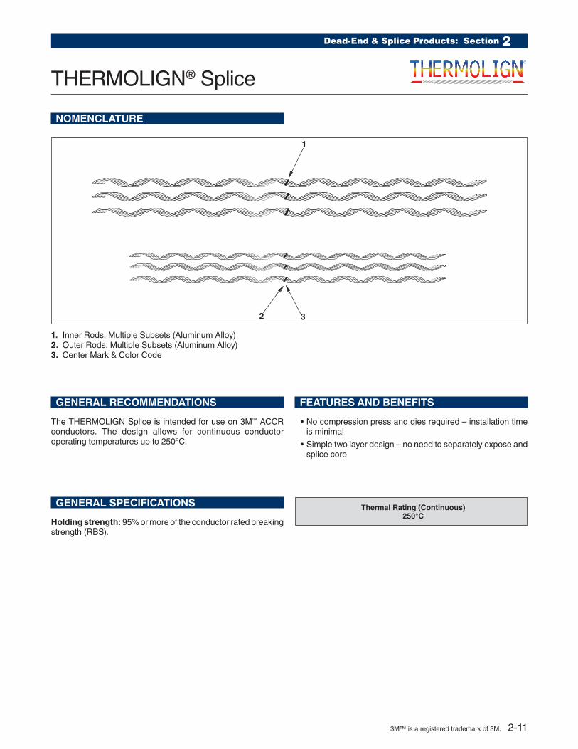
The THERMOLIGN Splice is intended for use on 3M™ ACCR conductors. The design allows for continuous conductor operating temperatures up to 250°C.
GENERAL SPECIFICATIONS
Holding strength: 95% or more of the conductor rated breaking strength (RBS).
1. Inner Rods, Multiple Subsets (Aluminum Alloy)2. Outer Rods, Multiple Subsets (Aluminum Alloy)3. Center Mark & Color Code
FEATURES AND BENEFITS
• No compression press and dies required – installation time is minimal
• Simple two layer design – no need to separately expose and splice core
1
2 3
Thermal Rating (Continuous)250°C
3M™ is a registered trademark of 3M. 2-11

THERMOLIGN® Splice
Catalog Number
Conductor Diameter Range Length in. (m)
Color CodeMin
in. (m)Max
in. (m) Inner Rods Outer Rods
TLSP-0100 0.720 (18.3) 0.720 (18.3) 118 (2.97) 108 (2.74) Blue
TLSP-0101 0.741 (18.8) 0.752 (19.1) 119 (3.02) 109 (2.76) Brown
TLSP-0102 0.772 (19.6) 0.783 (19.3) 121 (3.07) 111 (2.81) Pink
TLSP-0103 0.806 (20.5) 0.823 (20.9) 124 (3.15) 114 (2.89) Green
TLSP-0104 0.846 (21.5) 0.860 (21.8) 131 (3.32) 121 (3.07) Red
TLSP-0105 0.883 (22.4) 0.900 (22.9) 133 (3.37) 123 (3.12) Purple
TLSP-0106 0.901 (22.9) 0.914 (23.2) 135 (3.42) 125 (3.17) Yellow
TLSP-0107 0.927 (23.5) 0.930 (23.6) 136 (3.45) 126 (3.20) Orange
TLSP-0108 0.953 (24.2) 0.962 (24.4) 146 (3.70) 136 (3.45) Black
TLSP-0109 0.963 (24.5) 0.977 (24.8) 147 (3.73) 137 (3.48) Blue
TLSP-0110 0.990 (25.1) 0.994 (25.2) 149 (3.78) 139 (3.53) Brown
TLSP-0111 1.000 (25.4) 1.019 (25.9) 151 (3.83) 141 (3.58) Pink
TLSP-0112 1.036 (26.3) 1.063 (27.0) 152 (3.86) 142 (3.60) Green
TLSP-0113 1.081 (27.4) 1.092 (27.7) 154 (3.91) 144 (3.65) Red
TLSP-0114 1.108 (28.1) 1.140 (29.0) 159 (4.03) 149 (3.78) Black
TLSP-0115 1.162 (29.5) 1.175 (29.8) 162 (4.11) 152 (3.86) Purple
TLSP-0116 1.196 (30.4) 1.212 (30.8) 163 (4.14) 153 (3.88) Yellow
TLSP-0117 1.240 (31.5) 1.259 (32.0) 165 (4.19) 155 (3.93) Orange
TLSP-0118 1.290 (32.8) 1.302 (33.1) 171 (4.34) 161 (4.08) Black
TLSP-0119 1.338 (34.0) 1.345 (34.2) 174 (4.42) 164 (4.16) Blue
TLSP-0120 1.380 (35.1) 1.386 (35.2) 177 (4.49) 167 (4.24) Red
TLSP-0121 1.420 (36.1) 1.427 (36.2) 181 (4.59) 171 (4.34) Purple
TLSP-0122 1.465 (37.2) 1.466 (37.2) 183 (4.64) 173 (4.39) Yellow
TLSP-0123 1.492 (37.9) 1.505 (38.2) 185 (4.69) 175 (4.44) Orange
TLSP-0124 1.540 (39.1) 1.544 (39.2) 188 (4.77) 178 (4.52) Green
Conductor
OUTER SPLICE ROD LENGTH
FIRST LAYER SPLICE ROD LENGTH
2-12 3M™ is a registered trademark of 3M.

Motion Control: Section 3
THERMOLIGN® Twin Spacer
GENERAL INFORMATION
The THERMOLIGN Twin Spacer is simple to install and is shipped with the rods (6 per side).
The break-away bolt provides a clear indication that the proper installation torque has been achieved (no special tools required).
Conductor Spacing is 18 inches (457 mm), but also available in 13 inch (330 mm) spacing.
Catalog Number
Conductor Diameter Range
Min in. (mm)
Max in. (mm)
TLTS-0101 0.673 (17.1) 0.713 (18.1)
TLTS-0102 0.714 (18.1) 0.752 (19.1)
TLTS-0103 0.753 (19.1) 0.791 (20.1)
TLTS-0104 0.792 (20.1) 0.831 (21.1)
TLTS-0105 0.832 (21.1) 0.87 (22.1)
TLTS-0106 0.871 (22.1) 0.909 (23.1)
TLTS-0107 0.91 (23.1) 0.949 (24.1)
TLTS-0108 0.95 (24.1) 0.988 (25.1)
TLTS-0109 0.989 (25.1) 1.028 (26.1)
TLTS-0110 1.029 (26.1) 1.067 (27.1)
TLTS-0111 1.068 (27.1) 1.106 (28.1)
TLTS-0112 1.107 (28.1) 1.146 (29.1)
TLTS-0113 1.147 (29.1) 1.185 (30.1)
TLTS-0114 1.186 (30.1) 1.224 (31.1)
TLTS-0115 1.225 (31.1) 1.264 (32.1)
TLTS-0116 1.265 (32.1) 1.303 (33.1)
TLTS-0117 1.304 (33.1) 1.345 (34.2)
TLTS-0118 1.346 (34.2) 1.382 (35.1)
TLTS-0119 1.383 (35.1) 1.421 (36.1)
TLTS-0120 1.422 (36.1) 1.461 (37.1)
TLTS-0121 1.462 (37.1) 1.5 (38.1)
TLTS-0122 1.501 (38.1) 1.539 (39.1)
TLTS-0123 1.54 (39.1) 1.579 (40.1)
TLTS-0124 1.58 (40.1) 1.618 (41.1)
TLTS-0125 1.619 (41.1) 1.657 (42.1)
TLTS-0126 1.658 (42.1) 1.697 (43.1)
TLTS-0127 1.698 (43.1) 1.736 (44.1)
TLTS-0128 1.737 (44.1) 1.776 (45.1)
TLTS-0129 1.777 (45.1) 1.821 (46.3)
For 13 inch spacing add -13 to catalog number (Example: TLTS - 0112 - 13)
Thermal Rating Standard 250°C
3M™ is a registered trademark of 3M. 3-13
THERMOLIGN® Spacer Damper
GENERAL INFORMATION
NOMENCLATURE
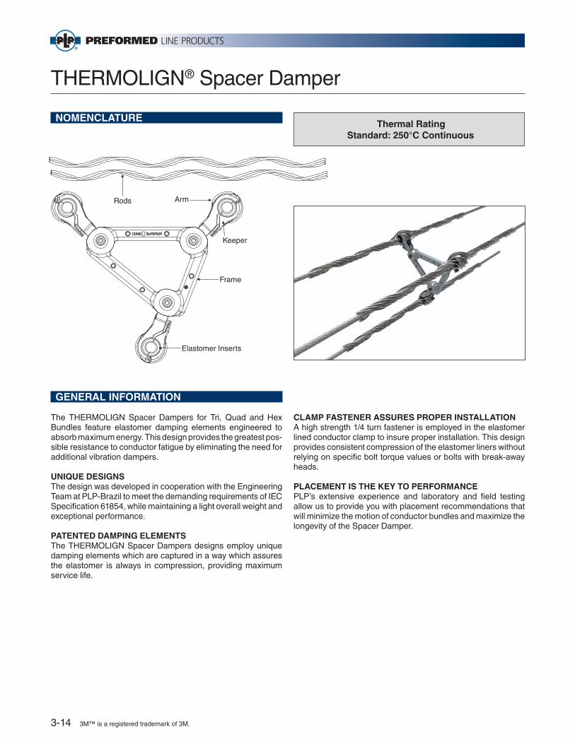
The THERMOLIGN Spacer Dampers for Tri, Quad and Hex Bundles feature elastomer damping elements engineered to absorb maximum energy. This design provides the greatest pos-sible resistance to conductor fatigue by eliminating the need for additional vibration dampers.
UNIQUE DESIGNSThe design was developed in cooperation with the Engineering Team at PLP-Brazil to meet the demanding requirements of IEC Specifi cation 61854, while maintaining a light overall weight and exceptional performance.
PATENTED DAMPING ELEMENTSThe THERMOLIGN Spacer Dampers designs employ unique damping elements which are captured in a way which assures the elastomer is always in compression, providing maximum service life.
CLAMP FASTENER ASSURES PROPER INSTALLATIONA high strength 1/4 turn fastener is employed in the elastomer lined conductor clamp to insure proper installation. This design provides consistent compression of the elastomer liners without relying on specifi c bolt torque values or bolts with break-away heads.
PLACEMENT IS THE KEY TO PERFORMANCEPLP’s extensive experience and laboratory and fi eld testing allow us to provide you with placement recommendations that will minimize the motion of conductor bundles and maximize the longevity of the Spacer Damper.
Thermal RatingStandard: 250°C Continuous
Arm
Keeper
Frame
Elastomer Inserts
Rods
3-14 3M™ is a registered trademark of 3M.

Motion Control: Section 3
THERMOLIGN® Spacer Damper
ORDERING INFORMATION
For standard 18" (457mm) sub-conductor spacing the catalog numbers are:
TLSDB-X45YZYZ is taken from the conductor range table belowX is 2 for Twin, 3 for Tri, 4 for Quad, 6 for Hex
Example:TLSDB-34529 is a Spacer Damper for a Tri Bundle of conductors within a diameter range of 1.107" to 1.146".
YZ Conductor Range in. (mm)
18 0.673-0.713 (17-18)
19 0.714-0.752 (18-19)
20 0.753-0.791 (19-20)
21 0.792-0.831 (20-21)
22 0.832-0.870 (21-22)
23 0.871-0.909 (22-23)
24 0.910-0.949 (23-24)
25 0.950-0.988 (24-25)
26 0.989-1.028 (25-26)
27 1.029-1.067 (26-27)
28 1.068-1.106 (27-28)
29 1.107-1.146 (28-29)
30 1.147-1.185 (29-30)
31 1.186-1.224 (30-31)
Contact PLP for other sub-conductor spacings and configurations.
Catalog Number Description
00071004 CUSHION-GRIP Spacer Damper installation tool
YZ Conductor Range in. (mm)
32 1.225-1.264 (31-32)
33 1.265-1.303 (32-33)
34 1.304-1.345 (33-34)
35 1.346-1.382 (34-35)
36 1.383-1.421 (35-36)
37 1.422-1.461 (36-37)
38 1.462-1.500 (37-38)
39 1.501-1.539 (38-39)
40 1.540-1.579 (39-40)
41 1.580-1.618 (40-41)
42 1.619-1.657 (41-42)
43 1.658-1.697 (42-43)
44 1.698-1.736 (43-44)
45 1.737-1.776 (44-45)
46 1.777-1.821 (45-46)
3M™ is a registered trademark of 3M. 3-15

VORTX™ Vibration Damper
NOMENCLATURE
1. Clamp & Keeper: The Clamp has an extruded hook shaped profi le to hang onto the cable or conductor while tightening the keeper. Together, the aluminum keeper and clamp capture the conductor to hold the damper assembly fi rmly onto the conductor or cable. Product identifi cation, installation torque, and lot number are permanently etched on the clamp.
2. Break-Away Bolt, Washer, and Lock Washer: The break-away bolt, washer, and lock washer are used to fas-ten the keeper to the clamp and secure the entire damper assembly to the cable or conductor. The materials used are galvanized steel.
3. Large Damper Weight: The VORTX damper design shown above has two weight sizes – this provides up to 4 resonant response frequencies (two for the large weight and two for the small weight) for more effective protection. The weight is a galvanized ductile iron casting.
4. Small Damper Weight: The small weight provides damping at higher frequencies. The weight is a galvanized ductile iron casting.
5. Messenger: The messenger is made of formed hard steel wires that are galvanized for corrosion resistance.
250°C when applied over THERMOLIGN® Suspension AGS Rods or Protector Rods
12
3
5
4
VORTX Dampers meet the requirements of IEC-61897
Damper Confi gurationCorona Rating
kV
VSD20 Single 200
VSD25 Single 200
VSD35 Single 260
Twin 345
VSD40 Single 230
Twin 345
Tri 400
Tri 400
Quad 400
VSD50 Single 330
Twin 400
VSD55 Twin 550
For use on ACCR Conductor
3-16 3M™ is a registered trademark of 3M.
Motion Control: Section 3
VORTX™ Vibration Damper
GENERAL RECOMMENDATIONS
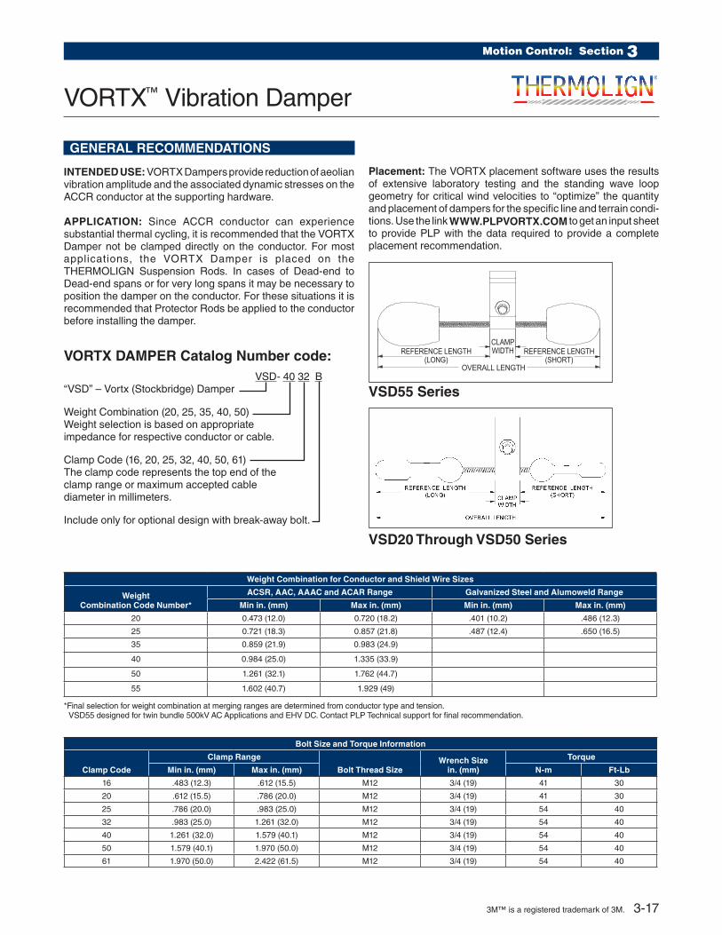
INTENDED USE: VORTX Dampers provide reduction of aeolian vibration amplitude and the associated dynamic stresses on the ACCR conductor at the supporting hardware.
APPLICATION: Since ACCR conductor can experience substantial thermal cycling, it is recommended that the VORTX Damper not be clamped directly on the conductor. For most applications, the VORTX Damper is placed on the THERMOLIGN Suspension Rods. In cases of Dead-end to Dead-end spans or for very long spans it may be necessary to position the damper on the conductor. For these situations it is recommended that Protector Rods be applied to the conductor before installing the damper.
Placement: The VORTX placement software uses the results of extensive laboratory testing and the standing wave loop geometry for critical wind velocities to “optimize” the quantity and placement of dampers for the specific line and terrain condi-tions. Use the link WWW.PLPVORTX.COM to get an input sheet to provide PLP with the data required to provide a complete placement recommendation.
VORTX DAMPER Catalog Number code: VSD- 40 32 B“VSD” – Vortx (Stockbridge) Damper
Weight Combination (20, 25, 35, 40, 50) Weight selection is based on appropriate impedance for respective conductor or cable.
Clamp Code (16, 20, 25, 32, 40, 50, 61) The clamp code represents the top end of the clamp range or maximum accepted cable diameter in millimeters.
Include only for optional design with break-away bolt.
VSD20 Through VSD50 Series
OVERALL LENGTH
REFERENCE LENGTH(SHORT)
REFERENCE LENGTH(LONG)
CLAMPWIDTH
VSD55 Series
Weight Combination for Conductor and Shield Wire Sizes
Weight Combination Code Number*
ACSR, AAC, AAAC and ACAR Range Galvanized Steel and Alumoweld Range
Min in. (mm) Max in. (mm) Min in. (mm) Max in. (mm)
20 0.473 (12.0) 0.720 (18.2) .401 (10.2) .486 (12.3)
25 0.721 (18.3) 0.857 (21.8) .487 (12.4) .650 (16.5)
35 0.859 (21.9) 0.983 (24.9)
40 0.984 (25.0) 1.335 (33.9)
50 1.261 (32.1) 1.762 (44.7)
55 1.602 (40.7) 1.929 (49)
*Final selection for weight combination at merging ranges are determined from conductor type and tension. VSD55 designed for twin bundle 500kV AC Applications and EHV DC. Contact PLP Technical support for final recommendation.
Bolt Size and Torque Information
Clamp Code
Clamp Range
Bolt Thread SizeWrench Size
in. (mm)
Torque
Min in. (mm) Max in. (mm) N-m Ft-Lb
16 .483 (12.3) .612 (15.5) M12 3/4 (19) 41 30
20 .612 (15.5) .786 (20.0) M12 3/4 (19) 41 30
25 .786 (20.0) .983 (25.0) M12 3/4 (19) 54 40
32 .983 (25.0) 1.261 (32.0) M12 3/4 (19) 54 40
40 1.261 (32.0) 1.579 (40.1) M12 3/4 (19) 54 40
50 1.579 (40.1) 1.970 (50.0) M12 3/4 (19) 54 40
61 1.970 (50.0) 2.422 (61.5) M12 3/4 (19) 54 40
3M™ is a registered trademark of 3M. 3-17

VORTX™ Vibration Damper
VORTX Damper Details
Catalog Number
Clamp Range Inches
Overall Lengthin. (mm)
Reference Length Long
in. (mm)Clamp Width
in. (mm)Bolt Sizein. (mm)
Install Torque
Assembled Weight lbs. (kg)
Min in. (mm)
Max in. (mm) Ft-lb N-m
VSD-2032B 0.983 (25.0) 1.261 (32.0) 15.1 (384) 6.9 (175) 2.200 (55.9) M12 x 70 40 54 4.4 (2.0)
VSD-2532B 0.983 (25.0) 1.261 (32.0) 12.9 (327) 6.4 (161) 2.200 (55.9) M12 x 70 40 54 5.4 (2.5)
VSD-2540B 1.261 (32.0) 1.579 (40.1) 13.1 (332) 6.4 (161) 2.380 (60.5) M12 x 70 40 54 5.7 (2.6)
VSD-3540B 1.261 (32.0) 1.579 (40.1) 15.1 (384) 7.0 (179) 2.380 (60.5) M12 x 70 40 54 7.9 (3.6)
VSD-4040B 1.261 (32.0) 1.579 (40.1) 20.4 (519) 10.5 (267) 2.380 (60.5) M12 x 70 40 54 11.1 (5.0)
VSD-4050B 1.579 (40.1) 1.970 (50.0) 20.6 (523) 10.5 (267) 2.500 (63.5) M12 x 70 40 54 11.4 (5.2)
VSD-4061B 1.970 (50.0) 2.403 (61.0) 21.1 (535) 10.5 (267) 3.000 (76.2) M12 x 75 40 54 12.1 (5.5)
VSD-5061B 1.970 (50.0) 2.403 (61.0) 24.5 (622) 12.1 (307) 3.000 (76.2) M12 x 75 40 54 12.5 (5.7)
VSD-5543 1.500 (38.1) 1.700 (43.2) 21.6 (548) 11.2 (285) 2.61 (66.3) M12 x 75 45 61 18.4 (8.3)
VSD-5549 1.700 (43.2) 1.950 (49.5) 21.8 (553) 11.3 (286) 2.75 (69.9) M12 x 50 50 68 18.5 (8.4)
PROTECTOR RODS FOR VORTX DAMPER
Protector Rods are required under the VORTX Damper for applica-tions (Dead-end to Dead-end spans and longer spans) where the placement would be off of the THERMOLIGN® Suspension rods.
PROTECTOR RODS
Thermal Rating (Continuous) 250°C
PLP Protector Rods
Catalog Number
Conductor Diameter Range
Rod Lengthin. (m)
Rod Diameter in. (mm)
Rods Per Set Color Code
Units Per Carton
Carton Weight lbs.(Kg)
Min in. (mm)
Max in. (mm)
PR-0135 0.378 (9.6) 0.423 (10.7) 12 (.30) 0.121 (3.1) 11 Yellow 50 10 (4.5)
PR-0137 0.424 (10.8) 0.475 (12.1) 12 (.40) 0.121 (3.1) 12 Brown 50 10 (4.5)
PR-0139 0.476 (12.1) 0.533 (13.5) 16 (.40) 0.121 (3.1) 13 Blue 50 14 (6.4)
PR-0141 0.534 (13.6) 0.585 (14.8) 16 (.40) 0.121 (3.1) 14 Green 50 14 (6.4)
PR-0142 0.586 (14.9) 0.618 (15.6) 16 (.40) 0.146 (3.7) 13 Orange 50 21 (9.5)
PR-0144 0.619 (15.7) 0.667 (16.9) 16 (.40) 0.146 (3.7) 14 Purple 50 21 (9.5)
PR-0146 0.668 (17.0) 0.722 (18.3) 20 (.50) 0.146 (3.7) 15 Red 50 29 (13.1)
PR-0148 0.723 (18.4) 0.816 (20.3) 20 (.50) 0.146 (3.7) 16 Black 50 29 (13.1)
PR-0150 0.817 (20.8) 0.898 (22.7) 20 (.50) 0.146 (3.7) 17 White 50 31 (14.1)
PR-0151 0.899 (22.8) 0.954 (24.2) 24 (.61) 0.167 (4.2) 17 Yellow 50 47 (21.3)
PR-0152 0.955 (24.3) 1.019 (25.8) 24 (.61) 0.182 (4.6) 16 Brown 25 29 (13.1)
PR-0154 1.020 (25.9) 1.064 (27.0) 24 (.61) 0.182 (4.6) 17 Blue 25 29 (16.1)
PR-0155 1.065 (27.1) 1.098 (27.8) 26 (.66) 0.204 (5.2) 16 Green 25 36 (16.3)
PR-0156 1.099 (27.9) 1.181 (29.9) 26 (.66) 0.250 (6.4) 14 Orange 25 48 (21.7)
PR-0158 1.182 (30.0) 1.298 (32.9) 26 (.66) 0.250 (6.4) 15 Purple 25 51 (23.1)
PR-0160 1.299 (33.0) 1.415 (35.9) 26 (.66) 0.250 (6.4) 16 Blue 20 44 (19.9)
PR-0162 1.416 (36.0) 1.543 (39.2) 26 (.66) 0.250 (6.4) 17 Yellow 20 48 (21.7)
PR-0163 1.544 (39.2) 1.685 (42.8) 26 (.66) 0.250 (6.4) 19 Brown 15 40 (18.1)
PR-0164 1.686 (42.8) 1.840 (46.7) 26 (.66) 0.250 (6.4) 20 Blue 15 42 (19.0)
3-18 3M™ is a registered trademark of 3M.
Repair Products: Section 4
Armor Rods
Thermal Rating (Continuous)ACCR Repair 250°C
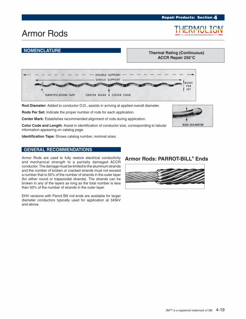
Rod Diameter: Added to conductor O.D., assists in arriving at applied overall diameter.
Rods Per Set: Indicate the proper number of rods for each application.
Center Mark: Establishes recommended alignment of rods during application.
Color Code and Length: Assist in identification of conductor size, corresponding to tabular information appearing on catalog page.
Identification Tape: Shows catalog number, nominal sizes.
NOMENCLATURE
GENERAL RECOMMENDATIONS
Armor Rods are used to fully restore electrical conductivity and mechanical strength to a partially damaged ACCR conductor. The damage must be limited to the aluminum strands and the number of broken or cracked strands must not exceed a number that is 50% of the number of strands in the outer layer (for either round or trapezoidal strands). The strands can be broken in any of the layers as long as the total number is less than 50% of the number of strands in the outer layer.
EHV versions with Parrot Bill rod ends are available for larger diameter conductors typically used for application at 345kV and above.
Armor Rods: PARROT-BILL® Ends
3M™ is a registered trademark of 3M. 4-19

CatalogNumber
EHV Armor Rod
Catalog Number
Conductor Diameter Range Per Carton
Lengthin. (m)
RodDiameterin. (mm)
RodsPerSet
ColorCode
Min in. (mm)
Max in. (mm) Units
Wt. lbs. (Kg)
AR-0124 0.552 (14.0) 0.5 85 (14.9) 25 46 (20.9) 60 (1.52) 0.182 (4.6) 11 Red
AR-0125 0.586 (14.9) 0.606 (15.4) 25 52 (23.6) 62 (1.57) 0.182 (4.6) 12 Black
AR-0126 0.607 (15.4) 0.63 (16.0) 25 54 (24.5) 64 (1.63) 0.182 (4.6) 12 Purple
AR-0127 0.631 (16.0) 0.655 (16.6) 25 54 (24.5) 64 (1.63) 0.182 (4.6) 12 Yellow
AR-0128 0.656 (16.7) 0.679 (17.2) 18 43 (19.5) 66 (1.68) 0.182 (4.6) 13 Brown
AR-0129 0.68 (17.3) 0.703 (17.9) 18 52 (23.6) 68 (1.73) 0.204 (5.2) 12 Blue
AR-0130 0.704 (17.9) 0.74 (18.8) 18 54 (24.5) 72 (1.83) 0.204 (5.2) 12 Green
AR-0131 0.741 (18.8) 0.782 (19.9) 18 59 (26.8) 72 (1.83) 0.204 (5.2) 13 Orange
AR-0132 0.783 (19.9) 0.814 (20.7) 15 66 (29.9) 76 (1.93) 0.25 (6.4) 11 Purple
AR-0133 0.815 (20.7) 0.845 (21.5) 15 66 (29.9) 76 (1.93) 0.25 (6.4) 11 Red
AR-0134 0.846 (21.5) 0.907 (23.0) 15 74 (33.6) 78 (1.98) 0.25 (6.4) 12 Blue
AR-0135 0.908 (23.1) 0.929 (23.6) 12 66 (29.9) 80 (2.03) 0.25 (6.4) 13 Green
AR-0136 0.93 (23.6) 0.976 (24.8) 12 72 (32.7) 88 (2.24) 0.25 (6.4) 13 White
AR-0137 AR-0500 0.977 (24.8) 1.016 (25.8) 9 50 (22.7) 92 (2.34) 0.31 (7.9) 11 Yellow
AR-0138 AR-0501 1.017 (25.8) 1.035 (26.3) 6 55 (24.9) 94 (2.39) 0.31 (7.9) 12 Brown
AR-0139 AR-0502 1.036 (26.3) 1.064 (27.0) 6 56 (25.4) 96 (2.44) 0.31 (7.9) 12 Blue
AR-0140 AR-0503 1.065 (27.1) 1.098 (27.9) 6 56 (25.4) 96 (2.44) 0.31 (7.9) 12 Green
AR-0141 AR-0504 1.099 (27.9) 1.139 (28.9) 6 62 (28.1) 100 (2.54) 0.31 (7.9) 12 Orange
AR-0142 AR-0505 1.14 (29.0) 1.161 (29.5) 6 63 (28.6) 101 (2.54) 0.31 (7.9) 13 Purple
AR-0143 AR-0506 1.162 (29.5) 1.208 (30.7) 6 69 (31.3) 102 (2.54) 0.31 (7.9) 13 Red
AR-0144 AR-0507 1.209 (30.7) 1.269 (32.2) 6 81 (36.7) 103 (2.54) 0.365 (9.3) 12 Black
AR-0145 AR-0508 1.27 (32.3) 1.327 (33.7) 6 81 (36.7) 104 (2.54) 0.365 (9.3) 12 White
AR-0146 AR-0509 1.328 (33.7) 1.39 (35.3) 3 45 (20.4) 105 (2.54) 0.365 (9.3) 13 Yellow
AR-0147 AR-0510 1.391 (35.3) 1.44 (36.6) 3 54 (24.5) 106 (2.54) 0.436 (11.1) 11 Brown
AR-0163 AR-0511 1.441 (36.6) 1.508 (38.3) 3 58 (26.3) 107 (2.54) 0.436 (11.1) 12 Blue
AR-0164 AR-0512 1.509 (38.3) 1.578 (40.1) 3 58 (26.3) 108 (2.54) 0.436 (11.1) 12 Green
AR-0165 AR-0513 1.579 (40.1) 1.651 (41.9) 3 60 (27.2) 109 (2.54) 0.436 (11.1) 13 Orange
AR-0166 AR-0514 1.652 (42.0) 1.728 (43.9) 3 60 (27.2) 110 (2.54) 0.436 (11.1) 13 Purple
AR-0167 AR-0516 1.729 (43.9) 1.809 (45.9) 3 64 (29.0) 111 (2.54) 0.436 (11.1) 14 Red
AR-0168 AR-0517 1.81 (46.0) 1.898 (48.2) 3 64 (29.0) 112 (2.54) 0.436 (11.1) 14 Black
AR-0169 AR-0518 1.899 (48.2) 1.991 (50.6) 3 68 (30.8) 113 (2.54) 0.436 (11.1) 15 White
AR-0170 AR-0519 1.992 (50.6) 2.09 (53.1) 3 68 (30.8) 114 (2.54) 0.436 (11.1) 15 Yellow
AR-0171 AR-0520 2.091 (53.1) 2.193 (55.7) 3 80 (36.3) 115 (2.54) 0.468 (11.9) 15 Brown
Armor Rods: Aluminum
4-20 3M™ is a registered trademark of 3M.

Repair Products: Section 4
NOMENCLATURE
Sub-Sets: Individual rods assembled and gritted into groups (subsets), corresponding to tabular information appearing on catalog page.
Center Mark: Establishes recommended alignment of rods during application.
Color Code and Length: Assist in identification of conduc-tor size, corresponding to tabular information appearing on catalog page.
Identification Tape: Shows catalog number, nominal sizes.
GENERAL RECOMMENDATIONS
Conductor Splices can be used on 3M™ ACCR conductor to repair damage to the Aluminum strands that exceeds the maximum number that can be repaired by Armor Rods.
Conductor Splices are capable of restoring the electrical con-ductivity of the conductor even if all of the aluminum strands have been broken or cracked. The composite core must be intact (undamaged).
EHV (345kV and above) versions of the conductor splices with Parrot Bill rod ends are available for the larger conductors typically used for higher line voltages.
Thermal Rating 250°C Continuous
Conductor Splices
Catalog Number Conductor Diameter Range
Length in. (m)
Rod Diameter in. (mm)
No. of Sub-sets
Color Code
Units Wt. lbs.(Kg)
StandardEHV (345kV and above)
Min in. (mm)
Max in. (mm) Per Carton
LS-0137 N/A 0.619 (15.7) 0.644 (16.4) 67 (1.70) 0.182 (4.6) 3 Yellow 25 58 (26.3)
LS-0139 N/A 0.672 (17.1) 0.7 (17.8) 70 (1.78) 0.204 (5.2) 3 Orange 25 68 (30.8)
LS-0140 N/A 0.701 (17.8) 0.729 (18.5) 77 (1.96) 0.25 (6.4) 3 Green 15 62 (28.1)
LS-0143 N/A 0.793 (20.1) 0.825 (21.0) 84 (2.13) 0.25 (6.4) 3 Red 3 18 (8.2)
LS-0144 N/A 0.826 (21.0) 0.85 (21.6) 86 (2.18) 0.25 (6.4) 3 Blue 3 19 (8.2)
LS-0147 N/A 0.93 (23.6) 0.968 (24.6) 108 (2.74) 0.31 (7.9) 4 Brown 3 37 (16.8)
LS-0148 N/A 0.969 (24.6) 1.008 (25.6) 111 (2.82) 0.31 (7.9) 4 Yellow 3 38 (16.8)
LS-0149 LSMS7953 1.009 (25.6) 1.05 (26.7) 121 (3.07) 0.31 (7.9) 4 Green 3 39 (17.7)
LS-0150 N/A 1.051 (26.7) 1.091 (27.7) 127 (3.23) 0.31 (7.9) 4 Black 3 45 (20.4)
LS-0151 LSMS4854 1.092 (27.7) 1.136 (28.9) 137 (3.48) 0.365 (9.3) 4 Purple 3 59 (26.8)
LS-0152 LSMS6275 1.137 (28.9) 1.183 (30.0) 141 (3.58) 0.365 (9.3) 4 Red 3 62 (28.1)
LS-0153 LSMS7955 1.184 (30.1) 1.232 (31.3) 143 (3.63) 0.365 (9.3) 4 Blue 3 63 (28.6)
LS-0154 LSMS8338 1.233 (31.3) 1.299 (33.0) 149 (3.78) 0.365 (9.3) 4 Green 3 65 (29.5)
LS-0155 LSMS7956 1.3 (33.0) 1.353 (34.4) 165 (4.19) 0.436 (11.1) 4 Yellow 3 101 (45.8)
LS-0156 LSMS14606 1.354 (34.4) 1.409 (35.8) 168 (4.27) 0.436 (11.1) 4 Brown 2 60 (27.2)
LS-0159 LSMS14465 1.529 (38.8) 1.591 (40.4) 184 (4.67) 0.436 (11.1) 4 Black 2 75 (34.0)
3M™ is a registered trademark of 3M. 4-21
Splice/Dead-end Shunt
Thermal Rating (Continuous)250°C
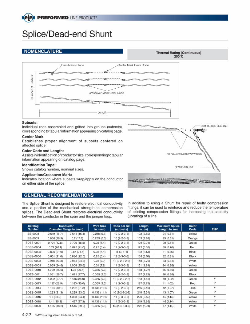
Subsets: Individual rods assembled and gritted into groups (subsets), corresponding to tabular information appearing on catalog page.
Center Mark: Establishes proper align ment of subsets centered on affected splice.
Color Code and Length: Assists in identifi cation of conductor size, corresponding to tabular in for ma tion ap pear ing on catalog page.
Identifi cation Tape: Shows catalog number, nom i nal sizes.
Application/Crossover Mark: Indicates location where subsets wrap/apply on the conductor on either side of the splice.
NOMENCLATURE
Identification Tape Center Mark Color Code
Crossover Mark Color Code
LengthLength
Num
ber o
f Sub
sets
GENERAL RECOMMENDATIONS
The Splice Shunt is designed to restore electrical conductivity and a portion of the mechanical strength to compression splices. The Dead-end Shunt restores electrical conductivity between the conductor in the span and the jumper loop.
In addition to using a Shunt for repair of faulty compression fi ttings, it can be used to reinforce and reduce the temperature of existing compression fi ttings for increasing the capacity (uprating) of a line.
Catalog Number
Conductor Diameter Range in. (mm)
Wire Size in. (mm)
Rods per Set(subsets)
Lengthin. (m)
Maximum Splice Length in. (m)
Color Code EHV
SS-0008 0.619 (15.7) 0.644 (16.4) 0.218 (5.5) 10 (2-2-3-3) 102 (2.59) 24 (0.61) Yellow
SS-0009 0.666 (16.9) 0.7 (17.8) 0.235 (6.0) 10 (2-2-3-3) 103 (2.62) 25 (0.61) Orange
SDES-0001 0.701 (17.8) 0.729 (18.5) 0.25 (6.4) 10 (2-2-3-3) 108 (2.74) 20 (0.51) Green
SDES-0004 0.79 (20.1) 0.825 (21.0) 0.25 (6.4) 11 (2-3-3-3) 122 (3.10) 30 (0.76) Red
SDES-0005 0.826 (21.0) 0.85 (21.6) 0.25 (6.4) 11 (3-4-4) 138 (3.51) 31 (0.76) Black
SDES-0006 0.851 (21.6) 0.886 (22.5) 0.25 (6.4) 12 (3-3-3-3) 138 (3.51) 32 (0.81) Black
SDES-0008 0.918 (23.3) 0.968 (24.6) 0.31 (7.9) 11 (2-2-2-2-3) 148 (3.76) 33 (0.81) White
SDES-0009 0.969 (24.6) 1.008 (25.6) 0.31 (7.9) 11 (2-3-3-3) 151 (3.84) 34 (0.86) Yellow
SDES-0010 1.009 (25.6) 1.05 (26.7) 0.365 (9.3) 10 (2-2-3-3) 168 (4.27) 35 (0.86) Green
SDES-0011 1.051 (26.7) 1.091 (27.7) 0.365 (9.3) 10 (2-2-3-3) 187 (4.75) 36 (0.86) Black
SDES-0012 1.092 (27.7) 1.136 (28.9) 0.365 (9.3) 11 (2-2-2-2-3) 183 (4.65) 40 (1.02) Green Y
SDES-0013 1.137 (28.9) 1.183 (30.0) 0.365 (9.3) 11 (2-3-3-3) 187 (4.75) 41 (1.02) Red Y
SDES-0014 1.184 (30.1) 1.232 (31.3) 0.436 (11.1) 10 (2-2-3-3) 216 (5.49) 42 (1.07) Blue Y
SDES-0015 1.233 (31.3) 1.299 (33.0) 0.436 (11.1) 10 (2-2-2-2-2) 218 (5.54) 43 (1.07) Green Y
SDES-0016 1.3 (33.0) 1.353 (34.4) 0.436 (11.1) 11 (2-3-3-3) 220 (5.59) 45 (1.14) Yellow Y
SDES-0018 1.41 (35.8) 1.467 (37.3) 0.436 (11.1) 11 (2-3-3-3) 219 (5.56) 46 (1.14) Yellow Y
SDES-0020 1.505 (38.2) 1.545 (39.2) 0.365 (9.3) 14 (2-3-3-3-3) 226 (5.74) 47 (1.14) White Y
COMPRESSION DEAD-END
DEAD-END SHUNT
COLOR MARKS AND CENTER MARK
4-22 3M™ is a registered trademark of 3M.
Installation Products: Section 5
Tensioning Grip Dead-end
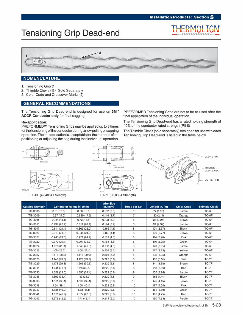
NOMENCLATURE
1. Tensioning Grip (1)2. Thimble Clevis (1) - Sold Separately 3. Color Code and Crossover Marks (2)
Catalog Number Conductor Range in. (mm)Wire Size in. (mm) Rods per Set Length in. (m) Color Code Thimble Clevis
TG-3006 0.61 (15.5) 0.63 (16.0) 0.102 (2.6) 9 77 (1.96) Purple TC-6F
TG-3009 0.67 (17.0) 0.689 (17.5) 0.144 (3.7) 7 83 (2.11) Orange TC-6F
TG-3011 0.711 (18.1) 0.73 (18.5) 0.128 (3.3) 8 88 (2.24) Brown TC-6F
TG-3015 0.794 (20.2) 0.814 (20.7) 0.144 (3.7) 8 94 (2.39) Purple TC-6F
TG-3017 0.841 (21.4) 0.866 (22.0) 0.162 (4.1) 8 101 (2.57) Black TC-6F
TG-3020 0.919 (23.3) 0.944 (24.0) 0.162 (4.1) 8 109 (2.77) Brown TC-6F
TG-3021 0.945 (24.0) 0.971 (24.7) 0.183 (4.6) 8 114 (2.90) Pink TC-6F
TG-3022 0.972 (24.7) 0.997 (25.3) 0.183 (4.6) 8 116 (2.95) Green TC-6F
TG-3024 1.029 (26.1) 1.049 (26.6) 0.183 (4.6) 8 120 (3.05) Purple TC-6F
TG-3025 1.05 (26.7) 1.08 (27.4) 0.204 (5.2) 8 127 (3.23) Yellow TC-6F
TG-3027 1.111 (28.2) 1.141 (29.0) 0.204 (5.2) 8 132 (3.35) Orange TC-6F
TG-3028 1.142 (29.0) 1.172 (29.8) 0.229 (5.8) 8 138 (3.51) Blue TC-7F
TG-3029 1.173 (29.8) 1.206 (30.6) 0.229 (5.8) 8 141 (3.58) Brown TC-7F
TG-3031 1.241 (31.5) 1.28 (32.5) 0.229 (5.8) 8 153 (3.89) Red TC-7F
TG-3033 1.321 (33.6) 1.355 (34.4) 0.229 (5.8) 9 155 (3.94) Purple TC-7F
TG-3035 1.393 (35.4) 1.43 (36.3) 0.229 (5.8) 9 163 (4.14) Black TC-7F
TG-3038 1.501 (38.1) 1.539 (39.1) 0.229 (5.8) 10 175 (4.45) Brown TC-7F
TG-3039 1.54 (39.1) 1.58 (40.1) 0.229 (5.8) 10 177 (4.50) Pink TC-7F
TG-3040 1.581 (40.2) 1.62 (41.1) 0.229 (5.8) 10 181 (4.60) Green TC-7F
TG-3041 1.621 (41.2) 1.677 (42.6) 0.229 (5.8) 10 187 (4.75) Red TC-7F
TG-3042 1.678 (42.6) 1.71 (43.4) 0.244 (6.2) 10 190 (4.83) Purple TC-7F
TC-7F (60,000# Strength)
2-7/8
2-1/43-1/2
SECTION A-A
AA
1-1/4
7-1/4
3-3/4
1
TC-6F (42,400# Strength)
CLEVIS PIN
COTTER PIN
THIMBLE CLEVIS, 60K
1
2
3
GENERAL RECOMMENDATIONS
The Tensioning Grip Dead-end is designed for use on 3M™
ACCR Conductor only for final sagging.
Re-application:PREFORMED™ Tensioning Grips may be applied up to 3 times for the tensioning of the conductor during a new pulling or sagging operation. The re-application is acceptable for the purpose of re-positioning or adjusting the sag during that individual operation.
PREFORMED Tensioning Grips are not to be re-used after the final application of the individual operation.
The Tensioning Grip Dead-end has a rated holding strength of 40% of the conductor rated strength (RBS)
The Thimble Clevis (sold separately) designed for use with each Tensioning Grip Dead-end is listed in the table below.
3M™ is a registered trademark of 3M. 5-23
NOTES
3M™ Aluminum Conductor Composite Reinforced (3M ACCR) is a registered trademark of 3M.

3M™ Aluminum Conductor Composite Reinforced (3M ACCR) is a registered trademark of 3M.

PLP OFFERS A WIDE ARRAY OF PRODUCT SOLUTIONS. WE KNOW WHAT IT TAKES TO PROVIDE THE RIGHT SOLUTIONS WITHIN THE VARIED GEOGRAPHY OF ENERGY AND COMMUNICATION INFRASTRUCTURES AROUND THE WORLD.
EMEA PLP FranceParis www.preformed.com
PLP Great Britain Andover, Hampshire www.preformed-gb.com
PLP PolandBielsko–Biala www.belos-plp.com.pl
PLP RussiaMoscow www.plp.ru
PLP SpainSeville www.plp-spain.com
PLP South Africa Pietermaritzburg www.preformedsa.co.za
PLP ThailandBangkok www.preformed.asia
PLP AustraliaSydney www.preformed.com.au
PLP New Zealand Electropar Ltd. Auckland www.electropar.co.nz
AMERICAS PLP U.S.A/World Headquarters Cleveland, OH www.preformed.com
Rogers, AR Albemarle, NC Albuquerque, NM www.DPWSolar.comPLP Canada Cambridge, Ontario www.preformed.on.ca Helix Uniformed Ltd. Lachine, Quebec www.helix-uni.ca PLP Mexico Querétaro www.plpmexico.com PLP Argentina Buenos Aires PLP Brazil São Paulo www.plp.com.br
ASIA PACIFIC PLP China Beijing www.plp.com.cnPLP IndonesiaJakarta www.preformed.asia/Indonesia
PLP MalaysiaKuala Lumpur www.preformed.asia/Malaysia
World HeadquartersPreformed Line Products Company660 Beta DriveCleveland, Ohio 44143
Mailing AddressP.O. Box 91129 Cleveland, Ohio 44101
Telephone: 440.461.5200Fax: 440.442.8816Web Site: www.preformed.comE-mail: [email protected]
© 2015 Preformed Line Products Company Printed in U.S.A.EN-ML-1130-107-15-5C


