International Journal of Rotating Machinery, 9(1): 41–47, 2003 Copyright c 2003 Taylor & Francis 1023-621X/03 $12.00 + .00 DOI: 10.1080/10236210390147371 Thermomechanical Behavior of Rotor with Rubbing Jerzy T. Sawicki and Alberto Montilla-Bravo Department of Mechanical Engineering, Cleveland State University, Cleveland, Ohio, USA Zdzislaw Gosiewski Aviation Institute, Warsaw, Poland This article presents an analytical study of the dynam- ics and stability of rotors subjected to rubbing due to con- tact with seals, taking account of associated thermal effects. The seal interaction force acting on the shaft gives rise to a friction force, which is a source of heating and can induce so-called spiral vibrations. A mathematical model that has been developed couples the heat-conduction equation with the equations for motion of the rotor. Numerical simulations have been conducted that show the thermomechanical be- havior of the rotor at various operating conditions. A proce- dure for analyzing the stability of multibearing rotors based on the system eigenvalue analysis and the state-space ap- proach has been proposed. Finally, the experimental data related to full annular rub have been presented. Keywords contact force, rotor rubbing, spiral vibration, stability, thermal bow Steam turbine rotors are generally large, precision-machined steel forgings with multiple turbine wheels machined directly out of a single forging for the attachment of buckets (blades). Such rotors can exceed 20 feet in length and can have body diameters exceeding 30 inches. As such, most steam turbine ro- tors are relatively flexible as compared to gas turbine rotors that employ a bolted construction. Because of this, most steam tur- bine rotors operate at speeds exceeding the first critical speed and sometimes operate near their second critical speed. One consequence of the integral rotor design and the relative flex- ibility of the rotors is that steam turbine rotors can be sensi- tive to rub-induced vibrations. This is unfortunate, since steam turbines employ multiple turbine stages to extract energy from Received 20 March 2001; accepted 18 October 2001. Address correspondence to Jerzy T. Sawicki, Department of Mechanical Engineering, Cleveland State University, Cleveland, OH 44115-2425, USA. E-mail: [email protected]the steam and therefore require many seals between the static and rotating elements to minimize parasitic leakage and maxi- mize thermal performance. Obviously, minimizing the rotor/seal clearances enhances thermal performance; the drawback to this approach is the increased risk of rotor/seal rubs and the resulting rotor vibration. This vibration may be self-correcting (stable), or self-propagating (unstable). In the worst case, the vibration can prohibit operation of the machine. The rubbing phenomenon in rotating machinery has been widely written about during the past 3 decades. It has been well recognized that under certain conditions rotating machinery ex- hibits vibrations that have chaotic content, that is, they present unpredictable behavior. Such behavior is driven by the existence of nonlinearities in the system, which could have many roots; one of them is the interaction of the rotating and stationary com- ponents (Bently, 1974; Ehrich, 1992; Goldman and Muszynska, 1993, 1994; Kraker et al., 1988; Muszynska, 1989; Padovan and Choy, 1987). Numerous papers have employed bifurcation diagrams or Poincar´ e maps to report on the chaotic nature of rub interactions; for example, see Bently (1974), Goldman and Muszynska (1993), and Sawicki (1999). Some authors have ex- plained the occurrence of such phenomena in terms of induced nonlinearities, for example, Sawicki (1999). A relatively small number of papers have addressed the ther- mal effect associated with the rubbing of a rotor against its sta- tionary components, which tends to heat the rotor at the angular location of the rub and is responsible for the rotor thermal bal- ance change, known as the Newkirk effect. Based on Taylor’s results (1924), Newkirk (1926) pointed out that when a rubbing rotor is running below its first balance resonance speed, the rub- induced lateral vibrations increase in time. Since then, many researchers have studied this effect. The most significant anal- yses have been provided by Dimarogonas (1973, 1983) and by Kellenberger (1980). Childs (1997) extended the Kellenberger model to include the effects of a radial clearance at the rub loca- tion. All these authors confirmed that these vibrations grow in amplitude and phase, resulting in spiral vibrations. One exam- ple is contacts between the rotor and seals, such as oil-lubricated 41
Jerzy T. Sawicki and Alberto Montilla-BravoDepartment of Mechanical Engineering, Cleveland State University, Cleveland, Ohio, USA
Zdzislaw GosiewskiAviation Institute, Warsaw, Poland
This article presents an analytical study of the dynam-ics and stability of rotors subjected to rubbing due to con-tact with seals, taking account of associated thermal effects.The seal interaction force acting on the shaft gives rise to afriction force, which is a source of heating and can induceso-called spiral vibrations. A mathematical model that hasbeen developed couples the heat-conduction equation withthe equations for motion of the rotor. Numerical simulationshave been conducted that show the thermomechanical be-havior of the rotor at various operating conditions. A proce-dure for analyzing the stability of multibearing rotors basedon the system eigenvalue analysis and the state-space ap-proach has been proposed. Finally, the experimental datarelated to full annular rub have been presented.
Steam turbine rotors are generally large, precision-machinedsteel forgings with multiple turbine wheels machined directlyout of a single forging for the attachment of buckets (blades).Such rotors can exceed 20 feet in length and can have bodydiameters exceeding 30 inches. As such, most steam turbine ro-tors are relatively flexible as compared to gas turbine rotors thatemploy a bolted construction. Because of this, most steam tur-bine rotors operate at speeds exceeding the first critical speedand sometimes operate near their second critical speed. Oneconsequence of the integral rotor design and the relative flex-ibility of the rotors is that steam turbine rotors can be sensi-tive to rub-induced vibrations. This is unfortunate, since steamturbines employ multiple turbine stages to extract energy from
Received 20 March 2001; accepted 18 October 2001.Address correspondence to Jerzy T. Sawicki, Department of
Mechanical Engineering, Cleveland State University, Cleveland, OH44115-2425, USA. E-mail: [email protected]
the steam and therefore require many seals between the staticand rotating elements to minimize parasitic leakage and maxi-mize thermal performance. Obviously, minimizing the rotor/sealclearances enhances thermal performance; the drawback to thisapproach is the increased risk of rotor/seal rubs and the resultingrotor vibration. This vibration may be self-correcting (stable),or self-propagating (unstable). In the worst case, the vibrationcan prohibit operation of the machine.
The rubbing phenomenon in rotating machinery has beenwidely written about during the past 3 decades. It has been wellrecognized that under certain conditions rotating machinery ex-hibits vibrations that have chaotic content, that is, they presentunpredictable behavior. Such behavior is driven by the existenceof nonlinearities in the system, which could have many roots;one of them is the interaction of the rotating and stationary com-ponents (Bently, 1974; Ehrich, 1992; Goldman and Muszynska,1993, 1994; Kraker et al., 1988; Muszynska, 1989; Padovanand Choy, 1987). Numerous papers have employed bifurcationdiagrams or Poincar´e maps to report on the chaotic nature ofrub interactions; for example, see Bently (1974), Goldman andMuszynska (1993), and Sawicki (1999). Some authors have ex-plained the occurrence of such phenomena in terms of inducednonlinearities, for example, Sawicki (1999).
A relatively small number of papers have addressed the ther-mal effect associated with the rubbing of a rotor against its sta-tionary components, which tends to heat the rotor at the angularlocation of the rub and is responsible for the rotor thermal bal-ance change, known as the Newkirk effect. Based on Taylor’sresults (1924), Newkirk (1926) pointed out that when a rubbingrotor is running below its first balance resonance speed, the rub-induced lateral vibrations increase in time. Since then, manyresearchers have studied this effect. The most significant anal-yses have been provided by Dimarogonas (1973, 1983) and byKellenberger (1980). Childs (1997) extended the Kellenbergermodel to include the effects of a radial clearance at the rub loca-tion. All these authors confirmed that these vibrations grow inamplitude and phase, resulting in spiral vibrations. One exam-ple is contacts between the rotor and seals, such as oil-lubricated
41
42 J. T. SAWICKI ET AL.
generator shaft seals (Kellenberger, 1980) or brush seals(Sawicki, 2000), which can generate an asymmetrical periph-eral temperature distribution and consequent rotor bow. If thatis coupled with rotor vibration, a spiraling phenomenon may beobserved. Another example is asymmetrical heating of the jour-nal in fluid-film bearings; for example, see Kirk and Balbahadur(2000). The thermally induced vibrations can lead to problems,such as difficulties in performing proper balancing or, in seriouscases, a situation in which it is impossible to operate the machine.
This article presents an analytical study of the dynamics ofrotors subjected to rubbing due to contact with seals and alsoconsiders thermal effects. The induced thermal bow is modeledon Kellenberger’s approach (1980). A mathematical model thathas been developed couples the heat conduction equation withthe equations of motion for the rotor. Numerical simulationsthat have been conducted show the thermomechanical behaviorof the rotor at various operating conditions. The procedure forstability analysis of the multibearing rotor systems based onthe eigenvalue analysis and state-space approach is proposed.Finally, the experimental data related to the full annular rubhave been presented.
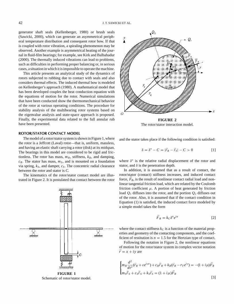
ROTOR/STATOR CONTACT MODELThe model of a rotor/stator system is shown in Figure 1, where
the rotor is a Jeffcott (Laval) rotor—that is, uniform, massless,and having an elastic shaft carrying a rotor (disk) at its midspan.The bearings in this model are considered to be rigid and fric-tionless. The rotor has mass,mR, stiffness,kR, and damping,cR. The stator has mass,mS, and is mounted on a foundationvia spring,kS, and damper,cS. The concentric radial clearancebetween the rotor and stator isC.
The kinematics of the rotor/stator contact model are illus-trated in Figure 2. It is postulated that contact between the rotor
FIGURE 1Schematic of rotor/stator model.
FIGURE 2The rotor/stator interaction model.
and the stator takes place if the following condition is satisfied:
δ = δ∗ − C = |r R− r S| − C > 0 [1]
whereδ∗ is the relative radial displacement of the rotor andstator, andδ is the penetration depth.
In addition, it is assumed that as a result of contact, therotor/stator (contact) stiffness increases, and induced contactforce, FR, is the result of nonlinear contact radial load and non-linear tangential friction load, which are related by the Coulombfriction coefficientµ. A portion of heat generated by frictionload Q1 diffuses into the rotor, and the portionQ2 diffuses outof the rotor. Also, it is assumed that if the contact condition inEquation (1) is satisfied, the induced contact force modeled bya simple model takes the form
F R = kCδneiα [2]
where the contact stiffnesskC is a function of the material prop-erties and geometry of the contacting components, and the coef-ficient of restitution isn = 1.5 for the Hertzian type of contact.
Following the notation in Figure 2, the nonlinear equationsof motion for the rotor/stator system in complex vector notationr = x + iy are
THERMAL BOW OF THE ROTORThe radial contact force,FR, acting on the shaft (see Figure 2)
gives rise to a friction force, which is a source of heating.Kellenberger (1980) used a heat-balance equation to arrive atthe following definition for excess temperatureT:
T(t) = k1
k3µωRFR(t)− k2
k3T(t) [4]
where
R is the rotor radius at which contact occurs;FR is the seal interactive force;µωRFR(t) is the power dissipated due to rubbing contact;k1 is the proportionality factor defining the proportion of gener-
ated power that enters the shaft;k2 is the proportionality factor that defines the amount of heat
lost from the shaft; andk3 is the factor that is proportional to the specific heat, density,
and geometry of the shaft in the vicinity of the rubbinglocation.
Following Kellenberger’s (1980) development, we assumed thatthe shaft’s thermal deflection (bow) was proportional to the ex-cess temperature,T, that is,
ρT = k4T [5]
whereρT is the rotating shaft with thermal deflection, andk4
is the proportionality factor containing the thermal expansioncoefficient, the material constants of the shaft, and the rotor’sgeometry, such as diameter, length, and bearings positions.
Now, taking into account the relationship in Equation (5), thetemperature, Equation (4), can be rewritten in terms of thermaldeflection in stationary coordinates as
˙r T (t)− iωr T (t)+ pµωRFR(t)+ qrT (t) = 0 [6]
where parameterspandqcharacterize heat input and heat output,respectively, for the shaft and are defined as
p = k1k4
k3, q = k2
k3[7]
Note that the rotor/stator’s motion, Equation (3), and thermalbow, Equation (6), are coupled by the normal and tangentialcomponents of the contact force and by the thermal bow vector,r T . Equations (3) and (6) are written in inertial coordinates.
NUMERICAL RESULTSThe equations of motion, Equations (3) and (6), can be written
in a nondimensional format by introducing the dimensionlesstimez= ωRt , and the following definitions (Kellenberger, 1980;Liebich, 1998):
ωR =√
kR
mR, p = pRkR, q = q
ωR, ξR = cR
2mRωR, η = ω
ωR
[8]
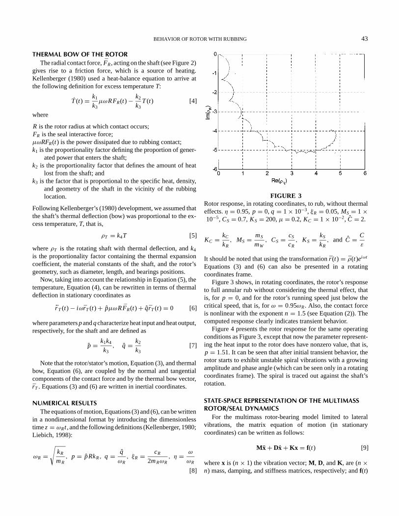
FIGURE 3Rotor response, in rotating coordinates, to rub, without thermaleffects.η = 0.95, p = 0, q = 1× 10⁻³, ξR = 0.05, MS= 1×10⁻⁵, CS= 0.7, KS= 200,µ = 0.2, KC = 1× 10⁻², C = 2.
KC = kC
kR, MS = mS
mW, CS = cS
cR, KS = kS
kR, and C = C
ε
It should be noted that using the transformationr (t) = ρ(t)eiωt
Equations (3) and (6) can also be presented in a rotatingcoordinates frame.
Figure 3 shows, in rotating coordinates, the rotor’s responseto full annular rub without considering the thermal effect, thatis, for p = 0, and for the rotor’s running speed just below thecritical speed, that is, forω = 0.95ωR. Also, the contact forceis nonlinear with the exponentn = 1.5 (see Equation (2)). Thecomputed response clearly indicates transient behavior.
Figure 4 presents the rotor response for the same operatingconditions as Figure 3, except that now the parameter represent-ing the heat input to the rotor does have nonzero value, that is,p = 1.51. It can be seen that after initial transient behavior, therotor starts to exhibit unstable spiral vibrations with a growingamplitude and phase angle (which can be seen only in a rotatingcoordinates frame). The spiral is traced out against the shaft’srotation.
STATE-SPACE REPRESENTATION OF THE MULTIMASSROTOR/SEAL DYNAMICS
For the multimass rotor-bearing model limited to lateralvibrations, the matrix equation of motion (in stationarycoordinates) can be written as follows:
Mx+ Dx+ Kx = f(t) [9]
wherex is (n× 1) the vibration vector;M , D, andK , are (n×n) mass, damping, and stiffness matrices, respectively; andf(t)
44 J. T. SAWICKI ET AL.
FIGURE 4Rotor response, in rotating coordinates, to rub, with thermal
is the excitation force vector. The properties of bearings areincluded in matricesD andK .
The equation of motion for the multimass rotor-bearing sys-tem with thermal bow takes the following form (Schmied, 1987):
Mx+ Dx+ Kx − K RTxThs= f(t) [10]
whereK R is (n × n) the stiffness matrix of the rotor withoutpedestals and bearings;T is the (n × 2) matrix describing thelinear relation between the thermal deflections of all coordinates
FIGURE 5Diagram of rotor/seal test rig with two disks.
and the translatory coordinates at the rubbing site (the hot spot);andxThs is (2× 1) the vector of thermally induced translatorydisplacements at the location of the hot spot (rubbing).
In stationary coordinates, the thermal equation can be writtenin the following form (Kellenberger, 1980):
I xThs+ Pxhs+QxThs= 0 [11]
whereI and0 are (2× 2) unity and zero matrices, respectively,and xhs is the (2× 1) vector of translatory displacements ofthe shaft at the location of the rubbing. The matricesP andQare (2× 2) and represent added heat and dissipated heat,respectively.
Equations (10) and (11) are coupled and can be combined asfollows:[
M 0
0 0
]{x
xThs
}+[
D 0
0 I
]{x
xThs
}+[
K −K RT
P Q
]{x
xThs
}={
f(t)
0
}[12]
whereP is (2× n) a matrix having coefficients of matrixP atthe columns corresponding to the translatory coordinatesxhs ofthe hot spot.
Introducing state variables, defined asx1 = x, x2 = x,x3 = xThs, and writing the equations
x1 = x2
Mx2 = −Kx1− Dx2+ K RTx3+ f
x3 = −Px1−Qx3
[13]
BEHAVIOR OF ROTOR WITH RUBBING 45
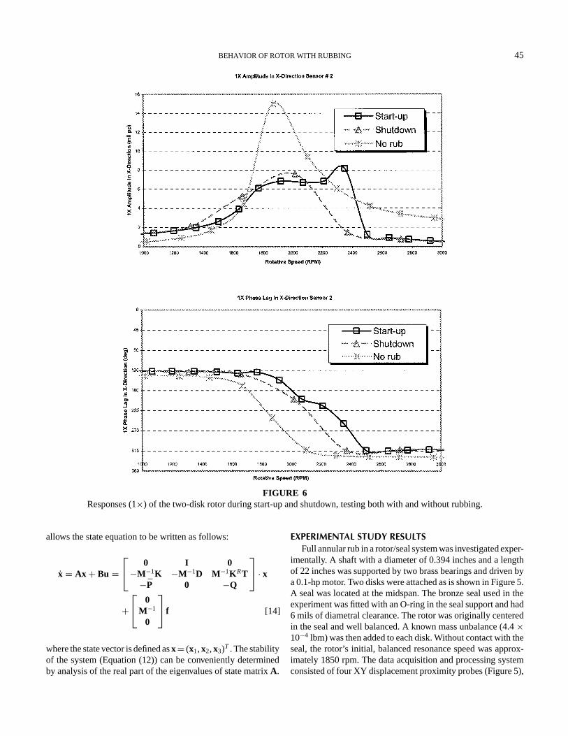
FIGURE 6Responses (1×) of the two-disk rotor during start-up and shutdown, testing both with and without rubbing.
allows the state equation to be written as follows:
x = Ax + Bu = 0 I 0−M−1K −M−1D M−1K RT−P 0 −Q
· x+ 0
M−1
0
f [14]
where the state vector is defined asx= (x1,x2,x3)T . The stabilityof the system (Equation (12)) can be conveniently determinedby analysis of the real part of the eigenvalues of state matrixA.
EXPERIMENTAL STUDY RESULTSFull annular rub in a rotor/seal system was investigated exper-
imentally. A shaft with a diameter of 0.394 inches and a lengthof 22 inches was supported by two brass bearings and driven bya 0.1-hp motor. Two disks were attached as is shown in Figure 5.A seal was located at the midspan. The bronze seal used in theexperiment was fitted with an O-ring in the seal support and had6 mils of diametral clearance. The rotor was originally centeredin the seal and well balanced. A known mass unbalance (4.4×10⁻⁴ lbm) was then added to each disk. Without contact with theseal, the rotor’s initial, balanced resonance speed was approx-imately 1850 rpm. The data acquisition and processing systemconsisted of four XY displacement proximity probes (Figure 5),
46 J. T. SAWICKI ET AL.
one speed probe, one Keyphasor probe to measure speed andphase, and ADRE software.
The 1× Bode plots of the X-direction responses of the two-disk rotor during the startup and shutdown testing, with andwithout rubbing, are presented in Figure 6. In the test with therubbing, the peak amplitude of vibration was limited by theclearance between the rotor and the seal. In addition, the inher-ent nonlinearity of the system gave rise not only to subharmonicvibrations (Sawicki et al., 1999), but also to amplitude jump dis-continuities, which occur when multitude solutions exist. This isclearly demonstrated in Figure 6. It is mainly during the startupthat the amplitude drops down; then it jumps up during the shut-down operation. The range of resonance speeds is much widerduring startup than it is during shutdown.
An excellent description of the phenomena observed wasprovided by Bently and colleagues (2000a, 2000b), who pre-sented insightful data concerning the experiment and studied theprecessional rub in great detail. They also analyzed the effectof unbalance, friction, rotative speed, rub frequency, and otherparameters.
SUMMARY AND CONCLUSIONSRubbing occurring in a rotor/stator/seal system was inves-
tigated analytically, numerically, and experimentally. The an-alytical model accounts for the thermal effect associated withrubbing. The characteristic spiral vibrations of the generic ro-tor/stator system was calculated. The issue of the stability ofmultimass rotor-bearing systems subjected to thermal bow dueto the occurrence of rub was addressed by developing a pro-cedure based on the state-space representation and eigenvalueanalysis. Finally, the characteristic for full annular rub amplitudejump has been demonstrated experimentally.
NOMENCLATURES Geometric center of the statorR Geometric center of the rotor (also radius of the rotor)G Rotor center of gravityε Mass eccentricitymR Rotor masskR Rotor stiffnesscR Rotor dampingmS Stator masskS Stator stiffnesscS Stator dampingrT Thermal bow in inertial coordinates frameω Angular speed of rotorωR Rotor critical speedFR Contact force vectorµ Coulomb friction coefficientkC Contact stiffness between rotor and statorC Concentric radial clearanceγ Position of the hot spotξR Rotor damping ratio
r R Rotor vibration vector in inertial coordinates frameρR Rotor vibration vector in rotating coordinates frameT Excess temperatureQ1 Heat entering the rotor per unit timeQ2 Heat loss per unit time
REFERENCESBently, D. E. 1974. Forced subrotative dynamic action of rotating ma-
Bently, D. E., Goldman, P., and Yu, J. J. 2000. Full annular rub inmechanical seals Part II: Analytical study.Proceedings of the 8thInternational Symposium on Transport Phenomena and Dynamicsof Rotating Machinery, ISROMAC-8, Honolulu, HI, pp. 1003–1010.
Bently, D. E., Goldman, P., and Yu, J. J. 2000. Full annular rub inmechanical seals Part I: Experimental results,Proceedings of the 8thInternational Symposium on Transport Phenomena and Dynamicsof Rotating Machinery, ISROMAC-8, Honolulu, HI, pp. 995–1002.
Childs, D. W. 1997. Clearance effects on spiral vibrations due to rub-bing. Proceedings of the 1997 ASME Design Engineering Confer-ences, DETC-97, 16th Biennial Conference on Mechanical Vibrationand Noise, Sacramento, CA, pp. 1–9.
Dimarogonas, A. D. 1973. Newkirk effect, thermally induced dynamicinstability of high-speed rotors. International Gas Turbine Confer-ence, Washington, DC. ASME Paper No. 73-GT-26.
Dimarogonas, A. D. 1983.Analytical Methods in Rotor Dynamics.London: Applied Science Publishers.
Ehrich, F. 1992. Observations of subcritical superharmonic and chaoticresponse in rotordynamics.ASME Journal of Vibration and Acoustics114:93–100.
Goldman, P., and Muszynska, A. 1993. Chaotic behavior of rotor/statorsystems with rubs.ASME Turbo Expo Conference, Cincinnati.
Goldman, P., and Muszynska, A. 1994. Dynamic effects in mechanicalstructures with gaps and impacting: Order and chaos.ASME Journalof Vibration and Acoustics116:541–547.
Kellenberger, W. 1980. Spiral vibrations due to seal rings in turbogener-ators: Thermally induced interaction between rotor and stator.ASMEJournal of Mechanical Design102:177–184.
Kirk, R. G., and Balbahadur, A. C. 2000. Thermal distortion syn-chronous rotor instability.Proceedings of the 7th InternationalConference on Vibrations in Rotating Machinery, ImechE, PaperC576/041, pp. 427–436, Nottingham, UK.
Kraker, D., Crooijmans, M. T. M., and Campen, D. H. 1988. The dy-namics of a rotor with rubbing.Proceedings of the 4th InternationalConference on Vibrations in Rotating Machinery, ImechE, PaperC284/88, pp. 297–303, Edinburgh, UK.
Liebich, R. 1998. Rub induced non-linear vibrations considering thethermo-elastic effect.Proceedings of the Fifth International Confer-ence on Rotor Dynamics, IFToMM, 802-815, Darmstadt, Germany.
Muszynska, A. 1989. Rotor-to-stator element rub-related vibration phe-nomena in rotating machinery—literature survey.Shock and Vibra-tion Digest21(3):3–11.
Newkirk, B. L. 1926. Shaft rubbing: Relative freedom of rotor shaftsfrom sensitiveness to rubbing contact when running above their crit-ical speeds.Mechanical Engineering48(8):830–832.
Padovan, J., and Choy, F. K. 1987. Nonlinear dynamics of ro-tor/blade/casing rub interactions.ASME Journal of Turbomachinery108:527–534.
BEHAVIOR OF ROTOR WITH RUBBING 47
Sawicki, J. T., Padovan, J., and Al-Khatib, R. 1999. The dynamicsof rotor with rubbing.International Journal of Rotating Machinery5(4):295–304.
Sawicki, J. T. 2000. Steam turbine rotors rub sensitivity study. Phase I:The development study. Technical report submitted to GE CorporateResearch & Development Center, Schenectady, NY.
Schmied, J. 1987. Spiral vibrations of rotors.Proceedings of the 11thBiennial ASME Vibration and Noise Conference.Boston, pp. 449–456.
Taylor, H. D. 1924.Rubbing Shafts Above and Below the Reso-nance Speed (Critical Speed), General Electric Company, R-16709,Schenectady, NY.