+ All Categories
Home > Documents > Thermoplastic polyurethane/polypropylene blends based on novel vane extruder: A study of morphology...

Thermoplastic polyurethane/polypropylene blends based on novel vane extruder: A study of morphology...

Date post: 23-Dec-2016
Category:
Upload: zan
View: 214 times
Download: 1 times
Share this document with a friend
9
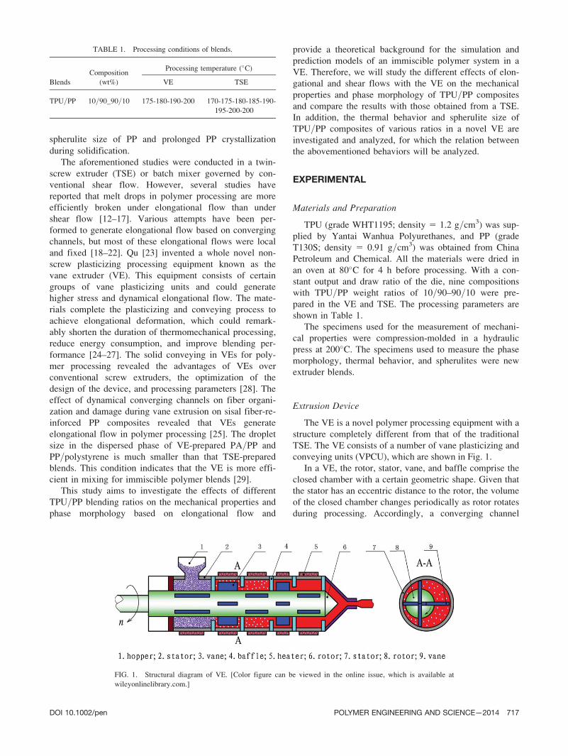
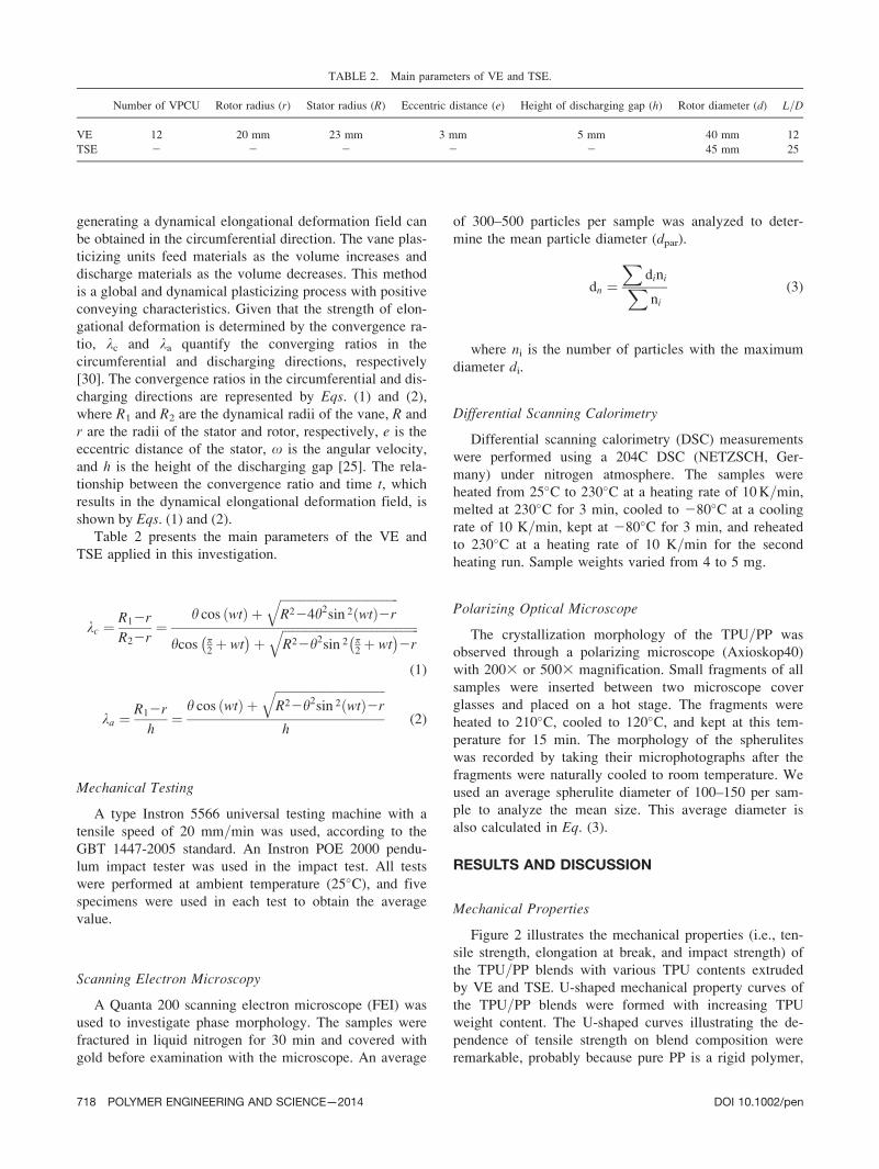
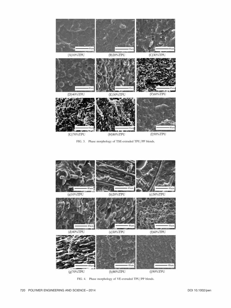
Thermoplastic Polyurethane=Polypropylene Blends Based on Novel Vane Extruder: A Study of Morphology and Mechanical Properties Shikui Jia, Jinping Qu, Weifeng Liu, Chengran Wu, Rongyuan Chen, Shufeng Zhai, Zan Huang National Engineering Research Center of Novel Equipment for Polymer Processing, Key Laboratory of Polymer Processing Engineering of the Ministry of Education, South China University of Technology, Guangzhou, 510640, China Thermoplastic polyurethane (TPU) polypropylene (PP) blends of different weight ratios were prepared with a self-made vane extruder (VE), which generates global dynamic elongational flow, and a traditional twin-screw extruder (TSE), which generates shear flow. The mechanical properties, phase morphology, thermal behavior, and spherulite size of the blends were investi- gated to compare the different processing techniques. Samples prepared with a VE had superior mechanical properties than the samples prepared with a TSE. Scan- ning emission micrographs show that the fiber morphol- ogy of the TPU=PP blends (<60 wt% TPU) was improved by elongational flow in VE. Differential scanning calorim- etry curves indicate that a dynamical elongational flow could improve the miscibility of the TPU=PP blends. The U-shaped spherulite size curve indicates the changes in the spherulite size, as observed from a polarization microscope. Interlocked spherulites also reveal the apparent partial miscibility of the TPU=PP blends under elongational flow. POLYM. ENG. SCI., 54:716–724, 2014. V C 2013 Society of Plastics Engineers INTRODUCTION Thermoplastic polyurethane (TPU) has been exten- sively used because of its superior mechanical properties such as high tensile strength, abrasion and tear resistance, oil and solvent resistance, and low temperature flexibility. TPU is a linear copolymer composed of microphase- separated hard and soft segments. The soft segments usu- ally form an elastomer matrix responsible for the elastic and low-temperature properties of TPU, whereas the hard segments act as multifunctional tie points that function as physical crosslinks and reinforcing fillers [1,2]. For cost reduction and improvement of thermal stability, chemical properties, mechanical properties, and processing per- formance, polypropylene (PP) could be added to TPU to create TPU=PP blends. Generally, TPU and PP blends are highly immiscible because of the large differences in their polarities and high interfacial tensions. Potschke et al. [3,4] reported that, at similar viscosity ratios, blends with polyether- based TPU have finer morphology than those with polyester-based TPU because of the lower free energy of the soft segment surfaces of polyether than that of polyes- ter. Moreover, the surface tension of the TPU hard and soft segments depends on the molecular weight of polyols and temperature. Wallheinke et al. [5,6] concluded that coalescence in the TPU=PP blends starts at a dispersed- phase content of approximately 1 wt%, and two different mechanisms of coalescence occurs in a quiescent melt. Lu and Macosko [7] blended TPU with three functional- ized PPs at different compositions. The blends with the two types of amine-functionalized PP exhibited enhanced synergy and finer morphology because of the higher reac- tivity of amine (primary and secondary) with urethane linkages. Shadi et al. [8] reported that TPU=PP blends are homogeneous with higher mechanical strength and blood compatibility than the commercial polyvinyl chloride blood bag. Kannan and Bhagawan [9] used nanoclay to reduce the surface energy of TPU hard segments and made them more compatible with nonpolar PP. Emi et al. [10,11] discovered that the crystallinity of TPU=PP blends and the PP crystallization temperature decrease with increasing TPU content. The addition of elastomeric TPU to PP significantly enhanced the Correspondence to: Jinping Qu; e-mail: [email protected] Contract grant sponsor: The National Nature Science Foundation of China; contract grant numbers: 10872071, 50973035 and 50903033; con- tract grant sponsor: National Key Technology R&D Program of China; contract grant numbers: 2009BAI84B05 and 2009BAI84B06; contract grant sponsor: The Fundamental Research Funds for the Central Univer- sities; contract grant number: 2012ZM0047; contract grant sponsor: Pro- gram for New Century Excellent Talents in University; contract grant number: NCET-11-0152; contract grant sponsor: Pearl River Talent Fund for Young Sci-Tech Researchers of Guangzhou City; contract grant number: 2011J2200058; contract grant sponsor: National Natural Science Foundation of China-Guangdong Joint Fundation Project; contract grant number: U1201242; contract grant sponsor: 973 Program; contract grant number 2012CB025902. DOI 10.1002/pen.23598 Published online in Wiley Online Library (wileyonlinelibrary.com). V C 2013 Society of Plastics Engineers POLYMER ENGINEERING AND SCIENCE—2014
Transcript

Thermoplastic Polyurethane=Polypropylene BlendsBased on Novel Vane Extruder: A Study of Morphologyand Mechanical Properties

Shikui Jia, Jinping Qu, Weifeng Liu, Chengran Wu, Rongyuan Chen, Shufeng Zhai, Zan HuangNational Engineering Research Center of Novel Equipment for Polymer Processing, Key Laboratory ofPolymer Processing Engineering of the Ministry of Education, South China University of Technology,Guangzhou, 510640, China

Thermoplastic polyurethane (TPU) polypropylene (PP)blends of different weight ratios were prepared with aself-made vane extruder (VE), which generates globaldynamic elongational flow, and a traditional twin-screwextruder (TSE), which generates shear flow. Themechanical properties, phase morphology, thermalbehavior, and spherulite size of the blends were investi-gated to compare the different processing techniques.Samples prepared with a VE had superior mechanicalproperties than the samples prepared with a TSE. Scan-ning emission micrographs show that the fiber morphol-ogy of the TPU=PP blends (<60 wt% TPU) was improvedby elongational flow in VE. Differential scanning calorim-etry curves indicate that a dynamical elongational flowcould improve the miscibility of the TPU=PP blends. TheU-shaped spherulite size curve indicates the changes inthe spherulite size, as observed from a polarizationmicroscope. Interlocked spherulites also reveal theapparent partial miscibility of the TPU=PP blends underelongational flow. POLYM. ENG. SCI., 54:716–724, 2014.VC 2013 Society of Plastics Engineers

INTRODUCTION

Thermoplastic polyurethane (TPU) has been exten-

sively used because of its superior mechanical properties

such as high tensile strength, abrasion and tear resistance,

oil and solvent resistance, and low temperature flexibility.

TPU is a linear copolymer composed of microphase-

separated hard and soft segments. The soft segments usu-

ally form an elastomer matrix responsible for the elastic

and low-temperature properties of TPU, whereas the hard

segments act as multifunctional tie points that function as

physical crosslinks and reinforcing fillers [1,2]. For cost

reduction and improvement of thermal stability, chemical

properties, mechanical properties, and processing per-

formance, polypropylene (PP) could be added to TPU to

create TPU=PP blends.

Generally, TPU and PP blends are highly immiscible

because of the large differences in their polarities and

high interfacial tensions. Potschke et al. [3,4] reported

that, at similar viscosity ratios, blends with polyether-

based TPU have finer morphology than those with

polyester-based TPU because of the lower free energy of

the soft segment surfaces of polyether than that of polyes-

ter. Moreover, the surface tension of the TPU hard and

soft segments depends on the molecular weight of polyols

and temperature. Wallheinke et al. [5,6] concluded that

coalescence in the TPU=PP blends starts at a dispersed-

phase content of approximately 1 wt%, and two different

mechanisms of coalescence occurs in a quiescent melt.

Lu and Macosko [7] blended TPU with three functional-

ized PPs at different compositions. The blends with the

two types of amine-functionalized PP exhibited enhanced

synergy and finer morphology because of the higher reac-

tivity of amine (primary and secondary) with urethane

linkages. Shadi et al. [8] reported that TPU=PP blends are

homogeneous with higher mechanical strength and blood

compatibility than the commercial polyvinyl chloride

blood bag. Kannan and Bhagawan [9] used nanoclay to

reduce the surface energy of TPU hard segments and

made them more compatible with nonpolar PP. Emi et al.

[10,11] discovered that the crystallinity of TPU=PP

blends and the PP crystallization temperature

decrease with increasing TPU content. The addition of

elastomeric TPU to PP significantly enhanced the

Correspondence to: Jinping Qu; e-mail: [email protected]

Contract grant sponsor: The National Nature Science Foundation of

China; contract grant numbers: 10872071, 50973035 and 50903033; con-

tract grant sponsor: National Key Technology R&D Program of China;

contract grant numbers: 2009BAI84B05 and 2009BAI84B06; contract

grant sponsor: The Fundamental Research Funds for the Central Univer-

sities; contract grant number: 2012ZM0047; contract grant sponsor: Pro-

gram for New Century Excellent Talents in University; contract grant

number: NCET-11-0152; contract grant sponsor: Pearl River Talent

Fund for Young Sci-Tech Researchers of Guangzhou City; contract grant

number: 2011J2200058; contract grant sponsor: National Natural Science

Foundation of China-Guangdong Joint Fundation Project; contract grant

number: U1201242; contract grant sponsor: 973 Program; contract grant

number 2012CB025902.

DOI 10.1002/pen.23598

Published online in Wiley Online Library (wileyonlinelibrary.com).

VC 2013 Society of Plastics Engineers

POLYMER ENGINEERING AND SCIENCE—2014

spherulite size of PP and prolonged PP crystallization

during solidification.

The aforementioned studies were conducted in a twin-

screw extruder (TSE) or batch mixer governed by con-

ventional shear flow. However, several studies have

reported that melt drops in polymer processing are more

efficiently broken under elongational flow than under

shear flow [12–17]. Various attempts have been per-

formed to generate elongational flow based on converging

channels, but most of these elongational flows were local

and fixed [18–22]. Qu [23] invented a whole novel non-

screw plasticizing processing equipment known as the

vane extruder (VE). This equipment consists of certain

groups of vane plasticizing units and could generate

higher stress and dynamical elongational flow. The mate-

rials complete the plasticizing and conveying process to

achieve elongational deformation, which could remark-

ably shorten the duration of thermomechanical processing,

reduce energy consumption, and improve blending per-

formance [24–27]. The solid conveying in VEs for poly-

mer processing revealed the advantages of VEs over

conventional screw extruders, the optimization of the

design of the device, and processing parameters [28]. The

effect of dynamical converging channels on fiber organi-

zation and damage during vane extrusion on sisal fiber-re-

inforced PP composites revealed that VEs generate

elongational flow in polymer processing [25]. The droplet

size in the dispersed phase of VE-prepared PA=PP and

PP=polystyrene is much smaller than that TSE-prepared

blends. This condition indicates that the VE is more effi-

cient in mixing for immiscible polymer blends [29].

This study aims to investigate the effects of different

TPU=PP blending ratios on the mechanical properties and

phase morphology based on elongational flow and

provide a theoretical background for the simulation and

prediction models of an immiscible polymer system in a

VE. Therefore, we will study the different effects of elon-

gational and shear flows with the VE on the mechanical

properties and phase morphology of TPU=PP composites

and compare the results with those obtained from a TSE.

In addition, the thermal behavior and spherulite size of

TPU=PP composites of various ratios in a novel VE are

investigated and analyzed, for which the relation between

the abovementioned behaviors will be analyzed.

EXPERIMENTAL

Materials and Preparation

TPU (grade WHT1195; density 5 1.2 g=cm3) was sup-

plied by Yantai Wanhua Polyurethanes, and PP (grade

T130S; density 5 0.91 g=cm3) was obtained from China

Petroleum and Chemical. All the materials were dried in

an oven at 80�C for 4 h before processing. With a con-

stant output and draw ratio of the die, nine compositions

with TPU=PP weight ratios of 10=90–90=10 were pre-

pared in the VE and TSE. The processing parameters are

shown in Table 1.

The specimens used for the measurement of mechani-

cal properties were compression-molded in a hydraulic

press at 200�C. The specimens used to measure the phase

morphology, thermal behavior, and spherulites were new

extruder blends.

Extrusion Device

The VE is a novel polymer processing equipment with a

structure completely different from that of the traditional

TSE. The VE consists of a number of vane plasticizing and

conveying units (VPCU), which are shown in Fig. 1.

In a VE, the rotor, stator, vane, and baffle comprise the

closed chamber with a certain geometric shape. Given that

the stator has an eccentric distance to the rotor, the volume

of the closed chamber changes periodically as rotor rotates

during processing. Accordingly, a converging channel

TABLE 1. Processing conditions of blends.

CompositionProcessing temperature (�C)

Blends (wt%) VE TSE

TPU=PP 10=90_90=10 175-180-190-200 170-175-180-185-190-

195-200-200

FIG. 1. Structural diagram of VE. [Color figure can be viewed in the online issue, which is available at

wileyonlinelibrary.com.]

DOI 10.1002/pen POLYMER ENGINEERING AND SCIENCE—2014 717

generating a dynamical elongational deformation field can

be obtained in the circumferential direction. The vane plas-

ticizing units feed materials as the volume increases and

discharge materials as the volume decreases. This method

is a global and dynamical plasticizing process with positive

conveying characteristics. Given that the strength of elon-

gational deformation is determined by the convergence ra-

tio, kc and ka quantify the converging ratios in the

circumferential and discharging directions, respectively

[30]. The convergence ratios in the circumferential and dis-

charging directions are represented by Eqs. (1) and (2),

where R1 and R2 are the dynamical radii of the vane, R and

r are the radii of the stator and rotor, respectively, e is the

eccentric distance of the stator, x is the angular velocity,

and h is the height of the discharging gap [25]. The rela-

tionship between the convergence ratio and time t, which

results in the dynamical elongational deformation field, is

shown by Eqs. (1) and (2).

Table 2 presents the main parameters of the VE and

TSE applied in this investigation.

kc ¼R12r

R22r¼

h cos ðwtÞ þffiffiffiffiffiffiffiffiffiffiffiffiffiffiffiffiffiffiffiffiffiffiffiffiffiffiffiffiffiffiffiffiffiffiffiffiffiffiffiR224h2sin 2ðwtÞ2r

q

hcos p2þ wt

� �þ

ffiffiffiffiffiffiffiffiffiffiffiffiffiffiffiffiffiffiffiffiffiffiffiffiffiffiffiffiffiffiffiffiffiffiffiffiffiffiffiffiffiffiffiffiffiR22h2sin 2 p

2þ wt

� �2r

q

(1)

ka ¼R12r

h cos ðwtÞ þffiffiffiffiffiffiffiffiffiffiffiffiffiffiffiffiffiffiffiffiffiffiffiffiffiffiffiffiffiffiffiffiffiffiffiffiR22h2sin 2ðwtÞ2r

q

h(2)

Mechanical Testing

A type Instron 5566 universal testing machine with a

tensile speed of 20 mm=min was used, according to the

GBT 1447-2005 standard. An Instron POE 2000 pendu-

lum impact tester was used in the impact test. All tests

were performed at ambient temperature (25�C), and five

specimens were used in each test to obtain the average

value.

Scanning Electron Microscopy

A Quanta 200 scanning electron microscope (FEI) was

used to investigate phase morphology. The samples were

fractured in liquid nitrogen for 30 min and covered with

gold before examination with the microscope. An average

of 300–500 particles per sample was analyzed to deter-

mine the mean particle diameter (dpar).

dn ¼X

diniXni

(3)

where ni is the number of particles with the maximum

diameter di.

Differential Scanning Calorimetry

Differential scanning calorimetry (DSC) measurements

were performed using a 204C DSC (NETZSCH, Ger-

many) under nitrogen atmosphere. The samples were

heated from 25�C to 230�C at a heating rate of 10 K=min,

melted at 230�C for 3 min, cooled to 280�C at a cooling

rate of 10 K=min, kept at 280�C for 3 min, and reheated

to 230�C at a heating rate of 10 K=min for the second

heating run. Sample weights varied from 4 to 5 mg.

Polarizing Optical Microscope

The crystallization morphology of the TPU=PP was

observed through a polarizing microscope (Axioskop40)

with 2003 or 5003 magnification. Small fragments of all

samples were inserted between two microscope cover

glasses and placed on a hot stage. The fragments were

heated to 210�C, cooled to 120�C, and kept at this tem-

perature for 15 min. The morphology of the spherulites

was recorded by taking their microphotographs after the

fragments were naturally cooled to room temperature. We

used an average spherulite diameter of 100–150 per sam-

ple to analyze the mean size. This average diameter is

also calculated in Eq. (3).

RESULTS AND DISCUSSION

Mechanical Properties

Figure 2 illustrates the mechanical properties (i.e., ten-

sile strength, elongation at break, and impact strength) of

the TPU=PP blends with various TPU contents extruded

by VE and TSE. U-shaped mechanical property curves of

the TPU=PP blends were formed with increasing TPU

weight content. The U-shaped curves illustrating the de-

pendence of tensile strength on blend composition were

remarkable, probably because pure PP is a rigid polymer,

TABLE 2. Main parameters of VE and TSE.

Number of VPCU Rotor radius (r) Stator radius (R) Eccentric distance (e) Height of discharging gap (h) Rotor diameter (d) L=D

VE 12 20 mm 23 mm 3 mm 5 mm 40 mm 12

TSE 2 2 2 2 2 45 mm 25

718 POLYMER ENGINEERING AND SCIENCE—2014 DOI 10.1002/pen

whereas pure TPU is a ductile elastomer. The initial

decrease in tensile strength with the addition of the sec-

ond phase reveals that the blends had weak interface

interaction (Fig. 2A). Incorporated PP may cause disrup-

tions in the TPU interchange of hydrogen bonding, facili-

tate crack propagation at weak phase interfaces, and

thereby lower the tensile strength of the blends [31]. The

minimum value of the impact strength was obtained at

60% TPU content. Thus, the minimum of 60% content

acts like a breaking point in the strength versus composi-

tion curve, which indicates a substantial structural and

morphological change caused by phase inversion [32].

Figure 2B demonstrates the elongation at the break of

blends of various TPU contents. The blends exhibited a

slight decrease in elongation at break with low TPU con-

tent (i.e., lower than 40%) but then increased with rising

TPU content. Elongation was obviously enhanced with

high TPU content. An increase in ductile elastomer in

rigid materials generally increases the toughness of

blends. Figure 2C depicts the impact strength of the

TPU=PP blends at various TPU contents. The impact

strength of the blends significantly improved at high TPU

content. The strength increased remarkably especially at

60% TPU content, indicating that a strong interface could

effectively transfer stress. As previously mentioned, when

the PP matrix has an inverted TPU, the mechanical prop-

erties are also inverted.

However, the mechanical properties of the VE-

extruded TPU=PP blends were superior to those of the

TSE-extruded blends (Fig. 2). In other words, elonga-

tional flow was more effective than shear flow in polymer

processing, which indicates that novel VE processing was

better than the traditional TSE. Elongational flow was

more effective probably because a positive displacement-

type flow dominates the solid conveying mechanism of

the VE. Moreover, the solids were not only compacted

but also transported regardless of their material properties,

which can remarkably shorten the thermo-mechanical his-

tory of the material and improve its suitability [28].

Moreover, higher pressure and shorter thermo-history are

achieved because of the positive displacement-type con-

veying characteristics of the VE compared with those of

the TSE [28]. Thermo-mechanical history and high pres-

sure can reduce macromolecule chain damage and particle

size, as well as generate fine particle distribution, which

are discussed in the following section.

Morphology Evolution

The SEMs of the TPU=PP blends with different TPU

contents extruded by VE and TSE are shown in Figs. 3

and 4. Particle size changed from small to large and then

back to small (Fig. 3A–I). Such evolution shows a U-

shaped inversion. In particular, the TPU=PP blend had a

bicontinuous phase at a 50% TPU weight content (Fig.

3E). In addition, when the TPU was in the dispersed

phase, the particle size was small at low TPU content

(<30%). The particle size remarkably increased with

increased TPU content (<50%).

The abovementioned changes are attributed to the

merging of several small particles caused by increasing

dispersed-phase TPU content. The particle size decreased

sharply at TPU > 60% in the matrix because PP viscosity

was lower than that of TPU during processing. PP was

easily dispersed, resulting in smaller particle size.

Figure 4A–I reveals the phase morphology of the

TPU=PP blends prepared by the novel VE. Two-phase

morphology was observed with low TPU content (<40%)

(Fig. 4A–D). More importantly, dispersed TPU formed

long fibers with a large aspect ratio because of the elon-

gational flow. The interface between the TPU and PP

matrices was sharp because of high interfacial tension.

The formation of TPU droplets could be clearly observed.

One fiber broke up and became droplets under the

FIG. 2. Mechanical properties as functions of blend composition. (A)

Tensile strength, (B) elongation at break, and (C) impact strength.

DOI 10.1002/pen POLYMER ENGINEERING AND SCIENCE—2014 719

FIG. 3. Phase morphology of TSE-extruded TPU=PP blends.

FIG. 4. Phase morphology of VE-extruded TPU=PP blends.

720 POLYMER ENGINEERING AND SCIENCE—2014 DOI 10.1002/pen

influence of the elongational deformation field. A bicon-

tinuous phase was also observed with a TPU content of

up to 50% (Fig. 4E). Interestingly, smaller TPU particles

could be found in the cross-section of the TPU compo-

nent, which has not been previously reported [8,10,11].

The existence of such particles indicates the effective dis-

persive mixing of materials by the elongational flow gen-

erated by VE. The dispersion of PP in the TPU matrix

created clear phase-separated morphology (Fig. 4F). This

morphology proves phase inversion and the abovemen-

tioned change in mechanical performance with 60% TPU

content. The processing conditions significantly affected

morphology development during melt mixing, especially

at a higher content of the dispersed phase and at a high

viscosity ratio [33]. At 70% TPU content, the elonga-

tional flow transformed the dispersed phase of the PP into

fibers (Fig. 4G). Some fibers broke up and became ellipti-

cal particles with size smaller than that with 60% TPU

content. In particular, at higher TPU content, the dis-

persed phase of the PP changed from a fibrillar to a drop-

let structure, and its particle size was reduced (Fig. 4H

and I). A few of the PP particles were also pulled out

from the matrix because of the sufficient interfacial adhe-

sion in Fig. 4I. Many of the pull-out hollows are shown

in Fig. 4F and G. Given the finer morphology and stron-

ger interfacial adhesion responsible for efficient stress

transfer across interfaces, the mechanical properties of the

blends considerably improved at high TPU content.

Figure 5 demonstrates the particle size and size distri-

bution with 90% TPU weight content prepared by VE

and TSE. The mean particle size decreased, and size dis-

tribution narrowed with 90% TPU content by VE extru-

sion compared with the case of TSE. The VE generated a

strong and dynamical elongational flow, decreasing parti-

cle size and narrowing its distribution. By contrast, the

TSE generated a fluctuating and longer thermo-history

shear flow, broadening particle size distribution. This dif-

ference proves that the mechanical properties of samples

extruded by VE are better than those of TSE.

The phase morphology of the 50=50 TPU=PP blend

sharply presented a bicontinuous phase under elongational

and shear flows (Table 3). The TPU hard segments,

which acted as multifunctional tie points, exhibited high

compatibility with the nonpolar PP. The TPU soft seg-

ments also exhibited high interaction with amorphous PP

under the influence of stronger elongational flow. More-

over, at 60% content, TPU seemed like a critical compo-

sition of coalescence in elongational and shear flow

induced by VE and TSE, respectively.

The mechanisms governing morphology development

include drop breakup and coalescence. Although drop

breakup is not dependent on the content of the dispersed

phase, coalescence is strongly influenced by blend com-

position. This phenomenon is caused by coalescence,

which has been previously observed [34]. Wallheinke

et al. [5] concluded that the reshaping of elongated drop-

lets and the breakup of fibers result in interparticle con-

tact and coalescence. After the coalescence of two

neighboring droplets, the resulting larger particle can

become closer to another particle, leading to further coa-

lescence. This process was repeated until the interparticle

distance became too long. The particle size of the

TPU=PP blends with increased TPU content under elon-

gational flow was smaller than that of blends under shear

flow (Table 3). More particles and narrow particle size

distribution can generate a greater and stronger interlock-

ing ratio between the PP and TPU phases. This result

clearly explains why the mechanical properties of the

FIG. 5. Particle size distributions of TPU (90%) extruded by VE and

TSE.

TABLE 3. Average diameter (lm) of droplets in blends extruded

by VE and TSE.

Blends TPU=PP

Content

ratio

10=90 20=80 30=70 40=60 50=50 60=40 70=30 80=20 90=10

VE 0.69 1.18 4.28 6.67 2 7.17 3.34 1.83 1.02

TSE 1.45 3.61 9.27 12.68 2 13.67 5.17 4.11 2.13FIG. 6. Melting behavior of VE-extruded TPU=PP blends.

DOI 10.1002/pen POLYMER ENGINEERING AND SCIENCE—2014 721

samples under elongational flow were superior to those of

samples under shear flow.

Thermal Behavior

Figures 6 and 7 present the DSC thermograms for the

blends with varied TPU=PP contents. All the DSC curves

show two melting (Fig. 6) and crystallizing (Fig. 7) endo-

thermic peaks, except for pure polymer PP and elastomer

TPU. The melt and crystallization enthalpies of the com-

ponents, as well as their characteristic melting and crys-

tallizing temperatures, are influenced by blending based

on elongational flow.

The heat of crystallization (DHc,PP) and melting

(DHm,PP) decreased continuously with increasing TPU

elastomer content, which suggests that the TPU addition

decreased the crystallinity of PP. Crystallization was

delayed in some polymer blends probably because of

decreased mobility and the slowed diffusion of the PP

chains by a partially miscible amorphous TPU=PP melt

[35]. Particularly, the crystallization (Tc,TPU) and melting

(Tm,TPU) temperatures remarkably increased with the PP

addition, compared with those of pure TPU (Tc 5

64.7�C, Tm 5 153.8�C). The temperatures increased

because the TPU soft segments interlocked well with the

PP amorphous region, and the regularity and degree of

crystallization of the TPU hard segments sharply

increased with lower PP content (<30%). The crystalliza-

tion temperature of PP (Tc,PP) also decreased from 121.1

to 116.5�C with the TPU incorporation, which indicates

that the crystallization ability of PP was reduced. Such

reduction probably resulted from the orientation and regu-

larity of PP molecular chains damaged differently by the

elastomer TPU, which facilitated diffusion from partially

miscible amorphous TPU=PP blends.

The thermal properties of the TPU=PP blends with dif-

ferent compositions are detailed in Table 4. The Tc,PP-TPU

and Tm,PP-TPU curves exhibited a U-shape with increasing

TPU weight content. In other words, when at low dis-

persed phase content (PP or TPU < 30%), the Tc or Tm

of both TPU and PP shifted toward each other. This

behavior suggests that TPU and PP were partially misci-

ble and that some molecular interactions occurred

between the two components. The interactions might have

originated from the change in the microphase separation

within TPU and the consequent miscibility between the

PP molecular chain and the soft segment (polyester) of

TPU.

Spherulite Morphology

The polarizing optical microscope (POM) photographs

of the VE-extruded TPU=PP blends are shown in Fig. 8.

The TPU=PP composites show the spherulite evolution

and structure. The spherulites of pure PP were fine and

close because of the isotacticity of PP (Fig. 8A). Figure

8G shows almost no spherulites because of the low

degree of TPU crystallinity.

The spherulites were improved by TPU incorporation,

and spherulite shape became more complete and nuclea-

tion density increased drastically (Fig. 8B). This phenom-

enon is attributed to the nucleation effect of TPU, which

provided much more heterogeneous nuclei and reduced

the size of the spherulites. Moreover, the presence of

TPU brought numerous spherulites in the limited space.

FIG. 7. Crystallization behavior of VE-extruded TPU=PP blends.

TABLE 4. Thermal properties of TPU=PP blends extruded by VE.

TPU=PP

content

ratio

Tm,PP

(�C)

Tm,TPU

(�C)

DHm,PP

(J=g)

DHm,TPU

(J=g)

Tc,TPU

(�C)

Tc,PP

(�C)

DHc,TPU

(J=g)

DHc,PP

(J=g)

Tm,PP-TPU

(�C)

Tc,PP-TPU

(�C)

0=100 166.4 2 109.37 2 2 121.1 2 96.36 2 2

10=90 168.0 197.1 65.9 0.26 95.8 116.5 0.29 78.56 29.1 20.7

30=70 168.5 197.6 49.77 0.44 96.3 115.8 0.47 59.82 29.1 19.5

50=50 166.4 196.9 30.52 0.89 98.5 118.7 1.43 32.93 30.5 20.2

70=30 165.6 196.0 17.13 1.47 101.6 118.9 3.53 10.32 30.4 17.3

90=10 169.4 194.0 8.45 2.39 102.4 120.1 6.31 1.36 24.6 17.7

100=0 2 153.8 2 1.21 64.7 2 0.87 2 2 2

Tm,PP-TPU denotes Tm,PP-Tm,TPU. Tc,PP-TPU denotes Tc,PP-Tc,TPU.

722 POLYMER ENGINEERING AND SCIENCE—2014 DOI 10.1002/pen

Accordingly, many spherulites were embedded in bulky

spherulites. The addition of great amounts of elastomers

to a semicrystalline PP matrix leads to spherulite growth

[36,37]. Spherulite size increased significantly, but spher-

ulite integrity was reduced (Fig. 8C and D). This phe-

nomenon was due to the further increase in TPU weight

content, which caused many PP nuclei to migrate to TPU.

Consequently, PP spherulites had more space to increase

and contain other smaller spherulites. Spherulite number

and integrity were reduced apparently because of matrix

reversal from PP to TPU (Fig. 8E and F). TPU also

reduced the crystallization ratio of PP in limited space,

and the limited space constrained the diffusing motion

and conformational transitions of the molecules during

crystal growth. These results diminished spherulite size

and caused more defects in the crystals.

Figure 9 shows the average diameter evolution of the

TPU=PP blends with different compositions. PP spherulite

size increased, and more diffuse PP spherulites were em-

bedded in the TPU soft segments. With a TPU weight

content >50%, spherulite size sharply decreased (Fig.

9E–G). Thus, the partial interlocking effect of the TPU

and PP chains may lead to the result of dsph. The PP

chains can remain in the TPU melt islands, and the TPU

chains (as a transport medium) partially included in the

amorphous intraspherulitic and interspherulitic regions of

the PP matrix lead to the apparent partial miscibility in

amorphous regions [38]. Further addition of the TPU to

the PP matrix caused the coalescence of the TPU melt

regions and the growth of the dispersed TPU particles

(Fig. 8E and F). The dispersed TPU particles may have

hindered the regular growth of the PP spherulites, and

thus, the effect of interlocking prevailed. The mixing of

the PP and TPU chains in the soft amorphous phases

reduced the mobility of the macromolecular chains, creat-

ing stiffer TPU=PP blends when PP was the matrix

phase [39].

CONCLUSIONS

As expected, the mechanical properties (i.e., tensile

strength, elongation at break, and impact strength) of the

VE-extruded TPU=PP blends were superior to those

extruded by conventional TSE. The phase morphology of

FIG. 8. Optical micrographs (3500) of VE-extruded TPU=PP blends.

FIG. 9. Spherulite size of the VE-extruded TPU=PP blends.

DOI 10.1002/pen POLYMER ENGINEERING AND SCIENCE—2014 723

the samples deduced influenced by the elongational flow

in VE exhibited smaller particle size and narrower size

distribution than those of TSE. These reductions were due

to the high pressure and dynamical elongational flow of

the novel VE. With either VE or TSE, the U-shaped

curve of particle size depended on the composition of the

dispersed phase. According to the DSC curves and POM

photographs of the TPU=PP blends, TPU and PP are par-

tially miscible and have stronger interlocking under elon-

gational flow. Finally, given the finer morphology and

stronger interfacial adhesion, the mechanical properties of

the blends were enhanced significantly with high TPU

content under the influence of elongational flow.

REFERENCES

1. H. Domininghaus, Plastics for Engineers, Materials, Proper-

ties, Applications, Hanser, Munich (1988).

2. B.M. Walker and C.P. Rader, Handbook of Thermoplastic

Elastomers, Van Nostrand Reinhold, New York (1988).

3. P. Potschke, K. Wallheinke, and H. Fritsche, J. Appl.Polym. Sci., 64, 749 (1997).

4. P. Potschke, J. Pionteck, and H. Stuz, Polymer, 43, 6965 (2002).

5. K. Wallheinke, P.W. Potschke, and W. Macosko, Polym.Eng. Sci., 39, 1022 (1999).

6. H. Stuz, W. Heckmann, and P. Potschke, J. Appl. Polym.Sci., 83, 2901 (2002).

7. Q.W. Lu and W. Macosko, Polymer, 45, 1981 (2004).

8. H. Ajili Shadi, G. Ebrahimi Nadereh, and T. Khorasani

Mohammad, J. Appl. Polym. Sci., 89, 2496 (2003).

9. M. Kannan and S.S. Bhagawan, J. Polym. Plast. Technol.,48, 871 (2009).

10. G.B. Emi, P. Andela, S. Ivan, and L. Mirela, J. Appl.Polym. Sci., 104, 3980 (2007).

11. G.B. Emi, P. Andela, S. Ivan, and L. Mirela, J. Appl.Polym. Sci., 117, 1378 (2010).

12. H.P. Grace, Chem. Eng. Commun., 14, 225 (1982).

13. C.E. Scott and W. Macosko, Polym. Bull., 26, 341 (1991).

14. L.A. Utracki and Z.H. Shi, Polym. Eng. Sci., 32, 1824 (1992).

15. J.M.H. Janssen and H.E.H. Mejijer, J. Rheol., 37, 597 (1993).

16. S C.E. Cott and W. Macosko, Polymer., 36, 461 (1995).

17. J. Kong and T.G. Simth, AIChE J., 42, 649 (1996).

18. Y. Suzaka, U.S. Patent, 4,334,783 (1982).

19. X.Q. Nguyen, D. Ormeaux, and L.A. Utracki, U.S. Patent,

5,4511,06A (1995).

20. C. Ranwendaal, T. Osswald, and P. Gramann, Proceedings

of the 56th SPE ANTEC, Atlanta, GA, 277 (1998).

21. C. Ranwendaal, T. Osswald, and P. Gramann, Int. Polym.Proc., 14, 28 (1999).

22. K. Chiba and K. Nakamura, J. Non-Newtonian Fluid.Mech., 78, 167 (1998).

23. J.P. Qu, CN. Patent, 200810026054.X (2008).

24. J.P. Qu, Z.T. Yang, and X.C. Yin, Polym. Plast. Technol.Eng., 48, 269 (2009).

25. J.P. Qu, L.M. Liu, and B. Tan, Polym. Compos., 33, 185

(2012).

26. J.P. Qu, CN. Eng. Sci., 10, 20 (2012).

27. J.P. Qu, X.Q. Zhao, and J.B. Li, J. Appl. Polym. Sci.; DOI:

10. 1002=app. 36806 (2012).

28. J.P. Qu, G.Z. Zhang, and H.Z. Chen, Polym. Eng. Sci., 10,

2147 (2012).

29. J.P. Qu, H.Z. Chen, and L.S. Liu, J. Appl. Polym. Sci.;DOI: 10. 1002=app. 38573 (2012).

30. G.F. Modlen, J. Mater. Sci., 4, 283 (1969).

31. C. Hepburn, Polyurethane Elastomers, Applied Science,

London (1982).

32. X. Zhang and Z. Yin, J. Appl. Polym. Sci., 62, 893 (1996).

33. B.D. Favis and D. Therrien, Polymer, 32, 1474 (1991).

34. J.J. Elmendorp and A.K. Van Der Vegt, Polym. Eng. Sci.,26, 1332 (1986).

35. G. Gorrassi, R. Pucciariello, V. Vilani, and V. Vittoria, J.Appl. Polym. Sci., 90, 3338 (2003).

36. G. Radonjic and I. �Smit, J. Polym. Sci. Part B: Polym.Phys., 39, 566 (2001).

37. I. �Smit, V. Musil, and I. �Svab, J. Appl. Polym. Sci., 91,

4072 (2004).

38. L. Tan, Y. Chen, W. Zhou, H. Nie, and F. Li, Polym.Degrad. Stab., 95, 1920 (2010).

39. E. Govorcin Bajsic, I. �Smit, and M. Leskovac, J. Appl.Polym. Sci., 104, 3980 (2007).

724 POLYMER ENGINEERING AND SCIENCE—2014 DOI 10.1002/pen


Recommended