THERMOSTATIC EXPANSION VALVES AND THERMOSTAT CONTROL DEVICES SPECIFICATIONS 03/2016 - EN ICMA S.p.a. via Garavaglia, 4 20012 Cuggiono (MI) – ITALY Tel. +39 02 97249134 / +39 02 97249135 Fax +39 02 97241550 www.icmaspa.it e-mail: [email protected]pag. 1 FUNCTION Thermostatic expansion valves are used to regulate and cut-off the flow of the heat transfer fluid that circulates inside air- conditioning system terminals (radiators, fan coils, etc.). Thermostat control devices are used in combination with the thermostatic expansion valves to automatically regulate ambient temperature wherever they are installed, keeping the temperature at a preset value. This avoids the needless wasting of heat and provides a considerable saving of energy. PRODUCT RANGE THERMOSTATIC EXPANSION VALVES – COPPER, MULTI-LAYER, POLYETHYLENE PIPE Angled Pipe fitting Radiator 840 Angled thermostatic expansion valve for multi-layer, polyethylene and copper pipe M24x1.5 G1/2” – G3/8” 842 Angled thermostatic expansion valve for multi-layer, polyethylene and copper pipe G1/2” G1/2” – G3/8” 852 Angled thermostatic expansion valve for multi-layer, polyethylene and copper pipe G3/4” G1/2” – G3/8” Straight 841 Straight thermostatic expansion valve for multi-layer, polyethylene and copper pipe M24x1.5 G1/2” – G3/8” 843 Straight thermostatic expansion valve for multi-layer, polyethylene and copper pipe G1/2” G1/2” – G3/8” 853 Straight thermostatic expansion valve for multi-layer, polyethylene and copper pipe G3/4” G1/2” – G3/8” THERMOSTATIC EXPANSION VALVES – IRON PIPE Angled Pipe fitting and Radiator 844 Angled thermostatic expansion valve for iron pipe G3/8” - G1/2” - G3/4” Straight 845 Straight thermostatic expansion valve for iron pipe G3/8” - G1/2” - G3/4” THERMOSTAT CONTROL DEVICE Item Code Connection 1100 Thermostat control device with built-in sensor, with liquid-sensitive component 821100AC20 M28x1.5 MATCHING FITTINGS For heating systems with copper, polyethylene or multi-layer polyethylene pipes, use the following fittings to connect ICMA thermostatic expansion valves to the heating system: Item Fitting Thread 90 Patented SICURBLOC fitting for copper pipe G1/2” – M24x1.5 93 EUROCONUS O-Ring leak-proof fitting for copper pipe G3/4” 98 Fitting for multi-layer, polyethylene pipe G1/2” 100 Fitting for multi-layer, polyethylene pipe M24x1.5 101 Fitting for multi-layer and polyethylene pipe G3/4” 119 Fitting for multi-layer and polyethylene pipe G3/4” 840-842-852 841-843-853 845 844 THERMOSTATIC EXPANSION VALVES 1100 THERMOSTAT CONTROL DEVICE
Transcript
THERMOSTATIC EXPANSION VALVES AND THERMOSTAT CONTROL DEVICES
Thermostatic expansion valves are used to regulate and cut-off the flow of the heat transfer fluid that circulates inside air-conditioning system terminals (radiators, fan coils, etc.). Thermostat control devices are used in combination with the thermostatic expansion valves to automatically regulate ambient temperature wherever they are installed, keeping the temperature at a preset value. This avoids the needless wasting of heat and provides a considerable saving of energy.
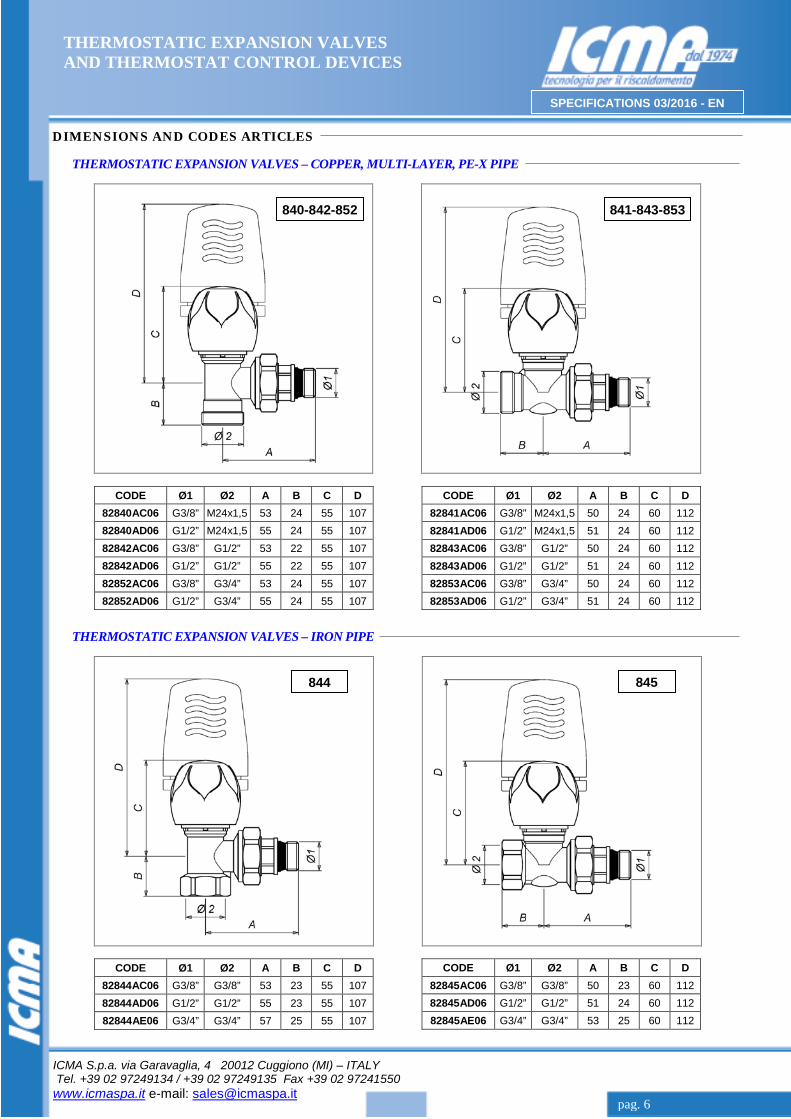
840 Angled thermostatic expansion valve for multi-layer, polyethylene and copper pipe M24x1.5 G1/2” – G3/8” 842 Angled thermostatic expansion valve for multi-layer, polyethylene and copper pipe G1/2” G1/2” – G3/8” 852 Angled thermostatic expansion valve for multi-layer, polyethylene and copper pipe G3/4” G1/2” – G3/8”
Straight
841 Straight thermostatic expansion valve for multi-layer, polyethylene and copper pipe M24x1.5 G1/2” – G3/8” 843 Straight thermostatic expansion valve for multi-layer, polyethylene and copper pipe G1/2” G1/2” – G3/8” 853 Straight thermostatic expansion valve for multi-layer, polyethylene and copper pipe G3/4” G1/2” – G3/8”
THERMOSTATIC EXPANSION VALVES – IRON PIPE
Angled Pipe fitting and Radiator
844 Angled thermostatic expansion valve for iron pipe G3/8” - G1/2” - G3/4”
Straight
845 Straight thermostatic expansion valve for iron pipe G3/8” - G1/2” - G3/4”
THERMOSTAT CONTROL DEVICE
Item Code Connection
1100 Thermostat control device with built-in sensor, with liquid-sensitive component 821100AC20 M28x1.5
MATCHING FITTINGS
For heating systems with copper, polyethylene or multi-layer polyethylene pipes, use the following fittings to connect ICMA thermostatic expansion valves to the heating system:
Item Fitting Thread
90 Patented SICURBLOC fitting for copper pipe G1/2” – M24x1.5 93 EUROCONUS O-Ring leak-proof fitting for copper pipe G3/4” 98 Fitting for multi-layer, polyethylene pipe G1/2” 100 Fitting for multi-layer, polyethylene pipe M24x1.5 101 Fitting for multi-layer and polyethylene pipe G3/4” 119 Fitting for multi-layer and polyethylene pipe G3/4”
ICMA thermostat control devices can be installed on all thermostatic expansion valves of this line to convert heating systems with manual operating mode to automatic operating mode. To install the thermostat control device, simply replace the thermostatic expansion valve knob with an ICMA thermostat control device. This is done with a few easy operations. These are described in detail in the paragraph “Thermostat Control Device Installation and Regulation”. The valves come in “straight” and “angled” versions so that they can be connected to two different types of pipes, at the side of the heating system: − The valves with GAS thread (side of heating system) are designed for connection to a steel pipe. − The valves with standard ICMA thread (side of heating system) are designed for connection to a copper pipe, a
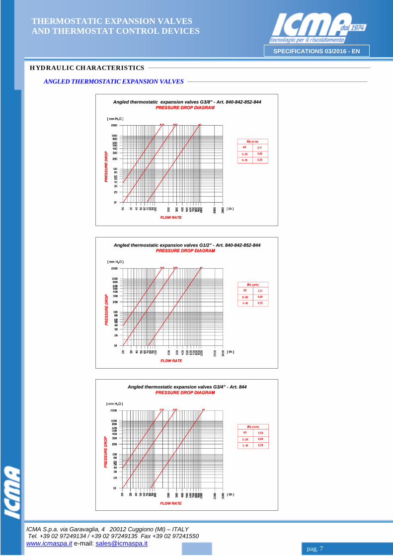
polyethylene pipe and a multi-layer polyethylene pipe, for which specific pipe fittings are provided. The valves are also equipped with a rubber, water-sealed socket. This allows the valve to be connected to the radiator easily and safely without the use of a sealant. Pressure loss can be detected by following the indications provided in the diagrams shown in the paragraph “Fluid Dynamic Characteristics”.
TECHNICAL SPECIFICATIONS
Performance Fluids used: Water and glycol solutions Maximum percentage of glycol: 50% Maximum operating pressure: 10 Bar Maximum differential pressure: 1 Bar (with control device mounted) Temperature of heat transfer fluid: 5 to 120°C Valve obturator travel: 3.5 mm Connection with thermostat control devices: M28x1.5
Materials Body, cap and socket union: CW617N Brass - UNI 12165 – Nickel-plated Large screw: CW614N Brass - UNI 12164 Spring and obturator control rod: Stainless steel Liquid sealings: Peroxy EPDM Control knob: RAL 9010 ABS White
VALVE INSTALLATION
Install ICMA thermostatic expansion valves on the heating system making sure to observe the direction of flow. The fluid must enter from the side on which the valve is connected to the system and go out toward the heating body. The following problems can occur if the valve is installed incorrectly: - A noise similar to a continuous sound of heavy hammering is due to the passage of fluid through the valve in the
wrong direction. This problem can only be solved by inverting the valve with holder on radiators that have this problem, thus restoring the correct direction of flow of the fluid inside the valve.
- A noise similar to a sound of heavy whistling during the succession of specified on and off times is due to an excessive flow inside the valve. This problem can be solved by keeping the system pressure under control, and equipping the system with variable rotation pumps along with differential pressure regulators, or by making use of differential by-pass valves.
Thermostat control devices are used to regulate ambient temperatures automatically wherever they are installed so that the temperature is kept at a preset value. Residential and working environments often contain other sources of heat, such as electrical appliances, stove-top cookers, computers, servers, and simple sunlight. Combined with the heating system, these additional heat sources cause a needless, uncontrolled increase in ambient temperature and the wasting of heat. Thermostat control devices detect variations in ambient temperature in the environments in which they are installed making it possible to keep the heat supplied by the heating system at optimal temperatures and to provide a considerable saving of energy. The ICMA, 1100, thermostat control device can be installed on all thermostatic expansion valves of this line. ICMA valves are supplied with the current manual control knob (for manual operation). The valves can be converted into thermostatic valves that function completely automatically by installing a thermostat control device. To install the thermostat control device, simply remove the thermostatic expansion valve control knob and replace it with the 1100 thermostat control device. This is done with just a few easy operations. These are described in detail in the paragraph “Thermostat Control Device Installation and Regulation”. ADJUSTMENT SCALE
Adjustment scale: ❅ to 5 Temperature adjustment range: 7 to 28°C The asterisk * indicates the freezing protection position, which corresponds to 7°C.
TECHNICAL SPECIFICATIONS
Performance
Minimum adjustment calibration (anti-freeze position): ts min 7°C (❅) Maximum adjustment calibration (position): ts max 28°C (5) Saving condition (position): 20°C (3) Maximum working pressure: PN 1000 KPa Maximum differential pressure: Δp 100 KPa Nominal capacity “qm N” (DP=10 KPa) angolo-diritta: qm N 190 Kg/h Maximum working temperature: 110°C Maximum storage temperature: 50°C Hysteresis: C 0.25 K Authority: a 0.9 Response time: Z 20 min Differential pressure influence: D 0,25 K Water temperature influence: W 0,7 K Use of the protection cap: 55°≈1K Connection to thermostatic expansion valves: M28x1,5
Thermostat control device conform with Standard: EN215 The thermostatic valve is fitted with manual adjustment handwheel (rotation)
Materials
Knob and stop ring: RAL 9010 ABS White Body and transmitter: RAL 9010 PA6 30% F.V. Sensor liquid: Thermostatic ethyl-acetate Connection ring: CW614N Brass - UNI 12164 - Nickel-plated Compensation pin: CW614N Brass - UNI 12164 Compensation pin spring: SH steel for springs - Phosphated
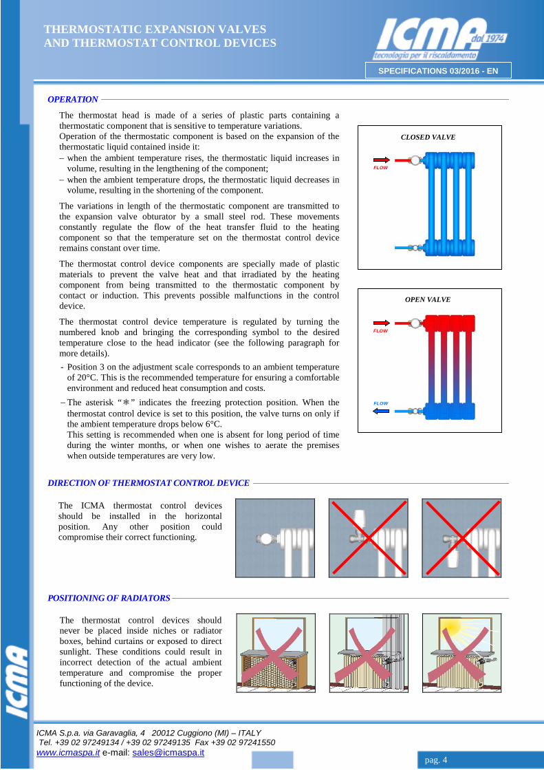
The thermostat head is made of a series of plastic parts containing a thermostatic component that is sensitive to temperature variations. Operation of the thermostatic component is based on the expansion of the thermostatic liquid contained inside it: − when the ambient temperature rises, the thermostatic liquid increases in
volume, resulting in the lengthening of the component; − when the ambient temperature drops, the thermostatic liquid decreases in
volume, resulting in the shortening of the component.
The variations in length of the thermostatic component are transmitted to the expansion valve obturator by a small steel rod. These movements constantly regulate the flow of the heat transfer fluid to the heating component so that the temperature set on the thermostat control device remains constant over time.
The thermostat control device components are specially made of plastic materials to prevent the valve heat and that irradiated by the heating component from being transmitted to the thermostatic component by contact or induction. This prevents possible malfunctions in the control device.
The thermostat control device temperature is regulated by turning the numbered knob and bringing the corresponding symbol to the desired temperature close to the head indicator (see the following paragraph for more details).
- Position 3 on the adjustment scale corresponds to an ambient temperature of 20°C. This is the recommended temperature for ensuring a comfortable environment and reduced heat consumption and costs.
− The asterisk “❅” indicates the freezing protection position. When the thermostat control device is set to this position, the valve turns on only if the ambient temperature drops below 6°C.
This setting is recommended when one is absent for long period of time during the winter months, or when one wishes to aerate the premises when outside temperatures are very low.
DIRECTION OF THERMOSTAT CONTROL DEVICE
POSITIONING OF RADIATORS
The thermostat control devices should never be placed inside niches or radiator boxes, behind curtains or exposed to direct sunlight. These conditions could result in incorrect detection of the actual ambient temperature and compromise the proper functioning of the device.
The ICMA thermostat control devices should be installed in the horizontal position. Any other position could compromise their correct functioning.
THERMOSTAT CONTROL DEVICE INSTALLATION AND REGULATION
CONVERSION OF MANUAL VALVES TO THERMOSTATIC VALVES
INSTALLATION OF THERMOSTAT CONTROL DEVICE
TEMPERATURE ADJUSTMENT
BLOCKING OF TEMPERATURE
LIMITATATION OF TEMPERATURE
The forked pin is sold separately from the control device.
FORKED PIN CODE:
111100AC06
Insert the forked pin inside these two holes and push until com-pletely inserted. The knob can now be move from 0 to the number set.
In order to limit the temperature, simply identify the two holes located right after the number set.
Insert the forked pin inside these two holes and push until com-pletely inserted. The knob is now blocked at the desired setting.
The same num-bering is also indicated on the lower part of the device. Identify the hole before and the hole after the number set.
Turn the thermo-stat control devi-ce knob to one of the setting num-bers from 0 to 5 shown on the knob. Setting ex-ample on the n°2.
Fasten the thermo-stat control device to the valve and screw the chrome-plated ring com-pletely onto the grey ring. Tighten with suitable wrench.
Set the control de-vice to setting 5 and install the de-vice on the valve body. Keep the indicator turned upward so that it is clearly visible.
Mount the grey ring supplied with the thermostat control device on the valve body. Keep the hexago-nal socket turned toward the operator.
The knob indicates the numbers from 0 to 5, which correspond to specific temperatures (see the adjustment scale shown at side). Set the desired temperature simply by turning the knob to the corresponding number close to the indicator.
Unfasten the whi-te adapter from the valve body by simultaneously pulling and ben-ding it .
Turn the knob in the counter clock-wise direction to remove it com-pletely from the valve.
Remove the pro-tective cover from the knob using a small screwdriver.