62
Thermowell Selection and Application PROPRIETY INFORMATION. ANY UNAUTHORISED DISCLOSURE IS STRICTLY FORBIDDEN
| Date post: | 17-Jul-2015 |
| Category: |
Engineering |
| Upload: | acez-sensing |
| View: | 132 times |
| Download: | 10 times |
Thermowell Selection and Application
PROPRIETY INFORMATION. ANY UNAUTHORISED DISCLOSURE IS STRICTLY FORBIDDEN
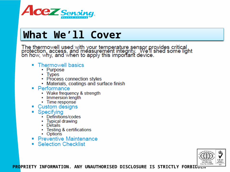
What We’ll Cover
PROPRIETY INFORMATION. ANY UNAUTHORISED DISCLOSURE IS STRICTLY FORBIDDEN
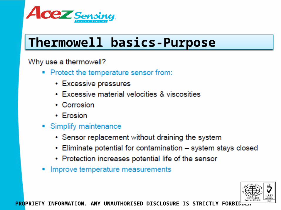
Thermowell basics-Purpose
PROPRIETY INFORMATION. ANY UNAUTHORISED DISCLOSURE IS STRICTLY FORBIDDEN
Thermowell Basics- Purpose
PROPRIETY INFORMATION. ANY UNAUTHORISED DISCLOSURE IS STRICTLY FORBIDDEN
A thermowell’s main purpose is to protect the temperature sensor to insure long life and accurate measurement. Maintenance is aided by allowing the sensor to be removed without having to drain the pipe or tank. Sensor changes can be done on the fly.
Thermowell Basics- Types
PROPRIETY INFORMATION. ANY UNAUTHORISED DISCLOSURE IS STRICTLY FORBIDDEN
Thermowell Basics- Types
PROPRIETY INFORMATION. ANY UNAUTHORISED DISCLOSURE IS STRICTLY FORBIDDEN
Thermowell types are designated by the style of stem or wetted portion of the well. Protection tubes are typically used for thermocouples and are not suited for use with RTDs because they do not provide enough support for the sensor. Most thermowells are machined from bar stock to insure integrity for high pressure applications. Flanges are joined to a thermowell stem most commonly by a welding process. Smaller wells may be constructed from tubing and have the end welded closed and a process connection welded on. These are typically used in low pressure applications.
Thermowell Basics- Stem types
PROPRIETY INFORMATION. ANY UNAUTHORISED DISCLOSURE IS STRICTLY FORBIDDEN
Thermowell Basics- Stem types
PROPRIETY INFORMATION. ANY UNAUTHORISED DISCLOSURE IS STRICTLY FORBIDDEN
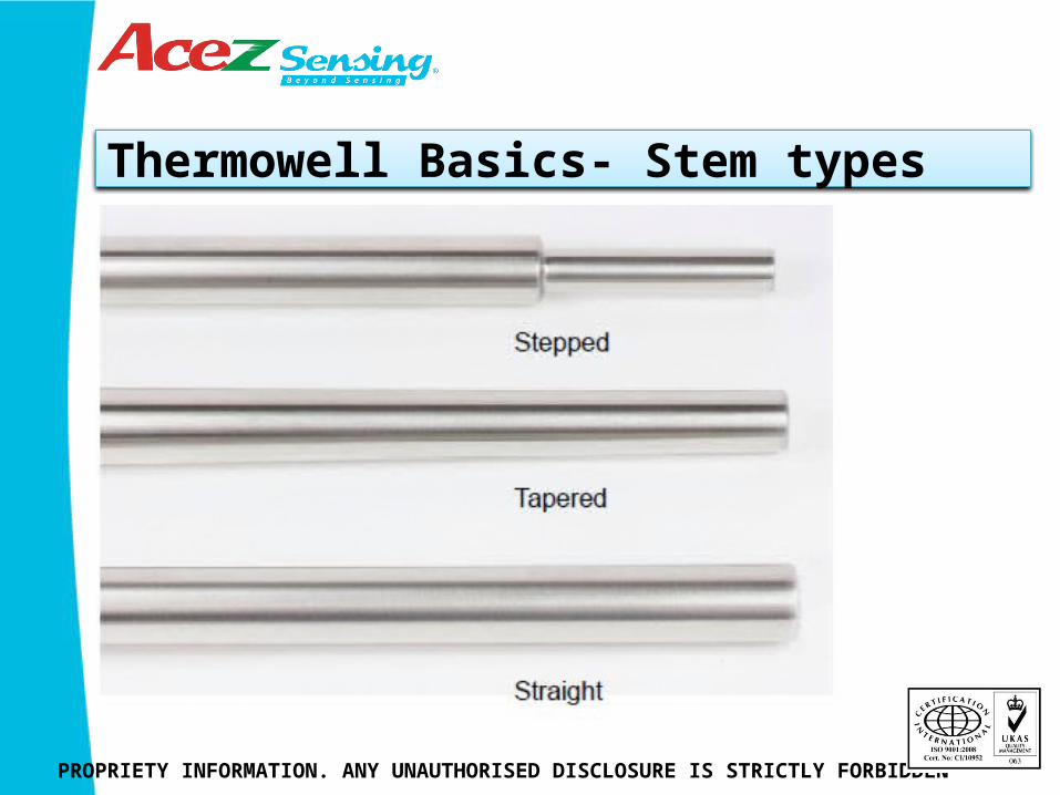
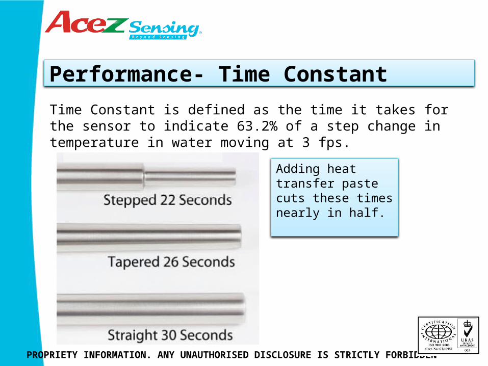
Stepped, sometimes referred to as reduced tip, wells are usually ¾” diameter and step down to ½” diameter to improve time response. Tapered wells are a balance between strength and time response. Straight wells are specified where increased life is desired due to corrosion or erosion.
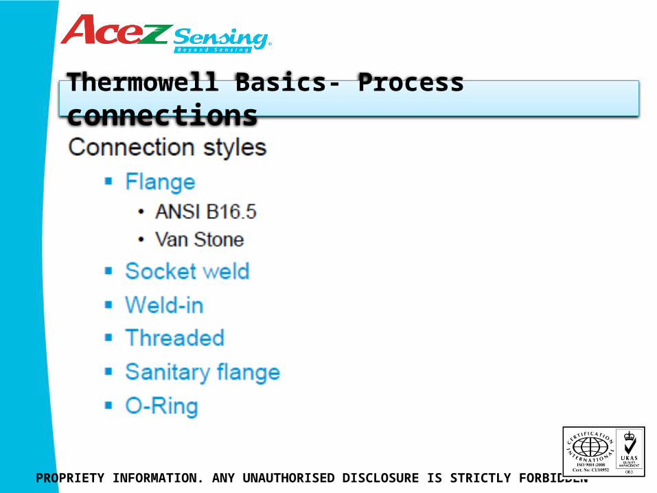
Thermowell Basics- Process connections
PROPRIETY INFORMATION. ANY UNAUTHORISED DISCLOSURE IS STRICTLY FORBIDDEN
PROPRIETY INFORMATION. ANY UNAUTHORISED DISCLOSURE IS STRICTLY FORBIDDEN
Connections to the process are accomplished with tapered pipe threads or adaptations of pipe or sanitary tubing flange connections. A blank or blind flange is modified to accept the thermowell stem and then easily attaches to standard flanges.
Weld‐in styles are used for convenience or where exposed threads may collect contaminants such as in food processing or pharmaceutical production.
A specialty type of connection incorporates an O‐ring to seal inside a sleeve welded to a tank. Sometimes referred to as an Ingold® fitting after the company that invented it for PH and oxygen sensors.
Thermowell Basics- Process connections
PROPRIETY INFORMATION. ANY UNAUTHORISED DISCLOSURE IS STRICTLY FORBIDDEN
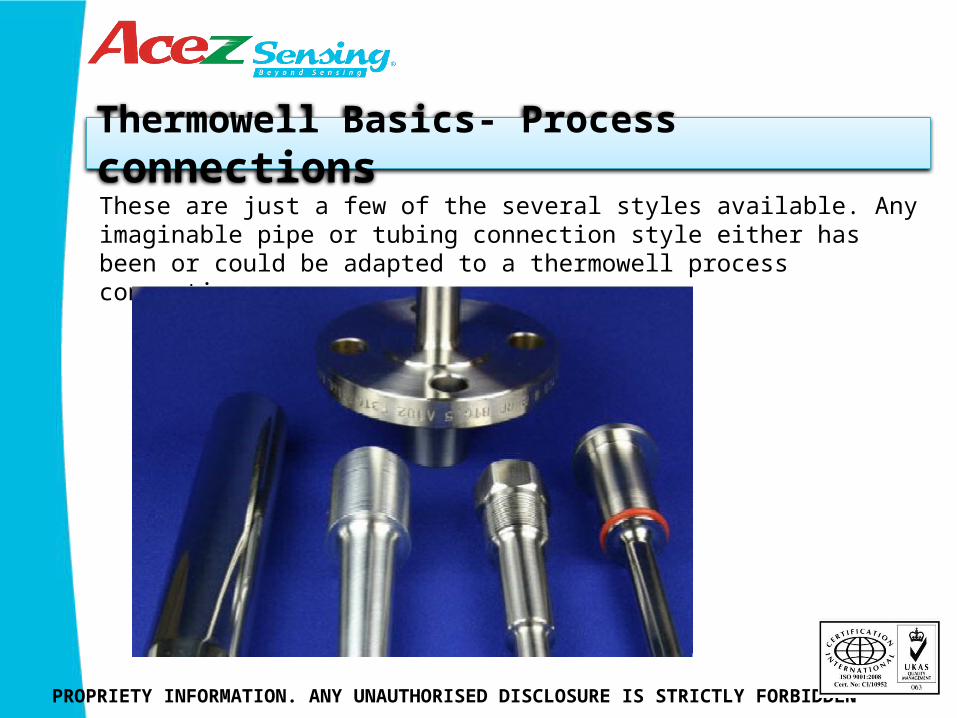
These are just a few of the several styles available. Any imaginable pipe or tubing connection style either has been or could be adapted to a thermowell process connection.
Thermowell Basics- Process connections
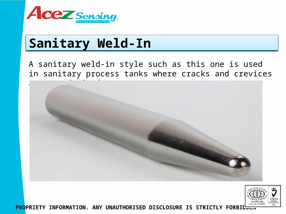
Sanitary Weld-In
PROPRIETY INFORMATION. ANY UNAUTHORISED DISCLOSURE IS STRICTLY FORBIDDEN
A sanitary weld‐in style such as this one is used in sanitary process tanks where cracks and crevices are not desired.
Sanitary Flange
PROPRIETY INFORMATION. ANY UNAUTHORISED DISCLOSURE IS STRICTLY FORBIDDEN
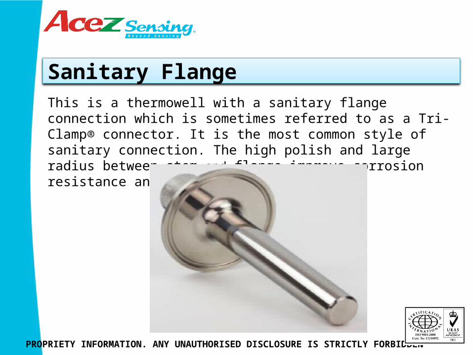
This is a thermowell with a sanitary flange connection which is sometimes referred to as a Tri‐Clamp® connector. It is the most common style of sanitary connection. The high polish and large radius between stem and flange improve corrosion resistance and make cleaning easier.
Sanitary with Process & Instrument Flange
PROPRIETY INFORMATION. ANY UNAUTHORISED DISCLOSURE IS STRICTLY FORBIDDEN
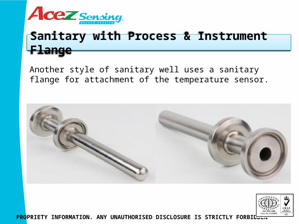
Another style of sanitary well uses a sanitary flange for attachment of the temperature sensor.

Sanitary –Easy Access Tri-clamp
PROPRIETY INFORMATION. ANY UNAUTHORISED DISCLOSURE IS STRICTLY FORBIDDEN
No tools are required to install or remove the sensor which makes for easier maintenance.
O-ring
PROPRIETY INFORMATION. ANY UNAUTHORISED DISCLOSURE IS STRICTLY FORBIDDEN
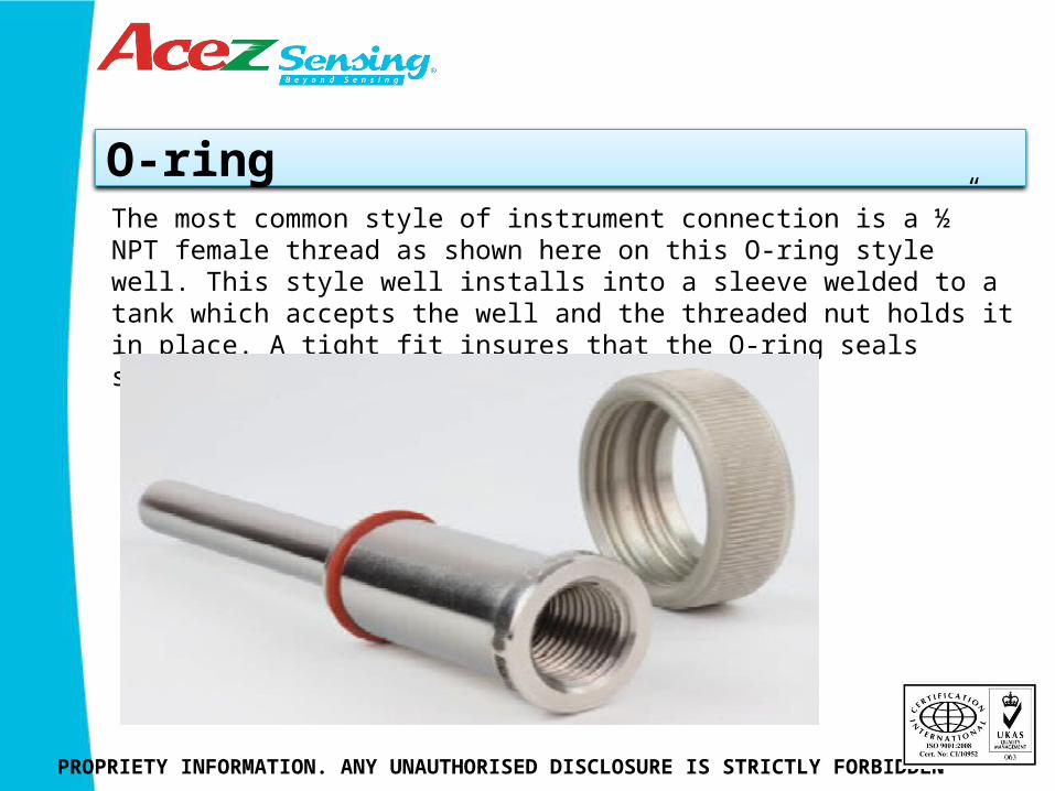
The most common style of instrument connection is a ½” NPT female thread as shown here on this O‐ring style well. This style well installs into a sleeve welded to a tank which accepts the well and the threaded nut holds it in place. A tight fit insures that the O‐ring seals securely.
Thermowell Basics-Process connections
PROPRIETY INFORMATION. ANY UNAUTHORISED DISCLOSURE IS STRICTLY FORBIDDEN
PROPRIETY INFORMATION. ANY UNAUTHORISED DISCLOSURE IS STRICTLY FORBIDDEN
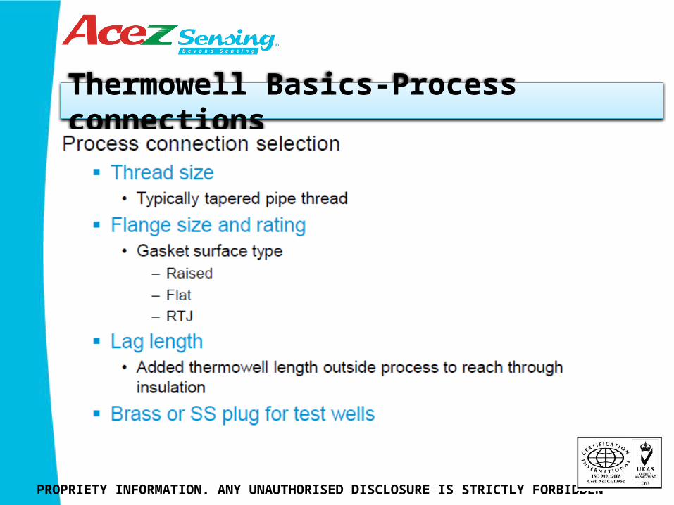
When selecting a process connection there are several things to consider. Threaded connections are the easiest, flange connection require a flange size, pressure rating, and gasket surface style.
Lag length is an extension of the non‐wetted portion of the well to reach through insulation or other obstacles to provide wrench access.
Typically specified for threaded wells. Test wells that sit empty for long periods of time should have a plug in the instrument connection to prevent debris from entering.
Thermowell Basics-Process connections
Materials
PROPRIETY INFORMATION. ANY UNAUTHORISED DISCLOSURE IS STRICTLY FORBIDDEN
Materials
PROPRIETY INFORMATION. ANY UNAUTHORISED DISCLOSURE IS STRICTLY FORBIDDEN
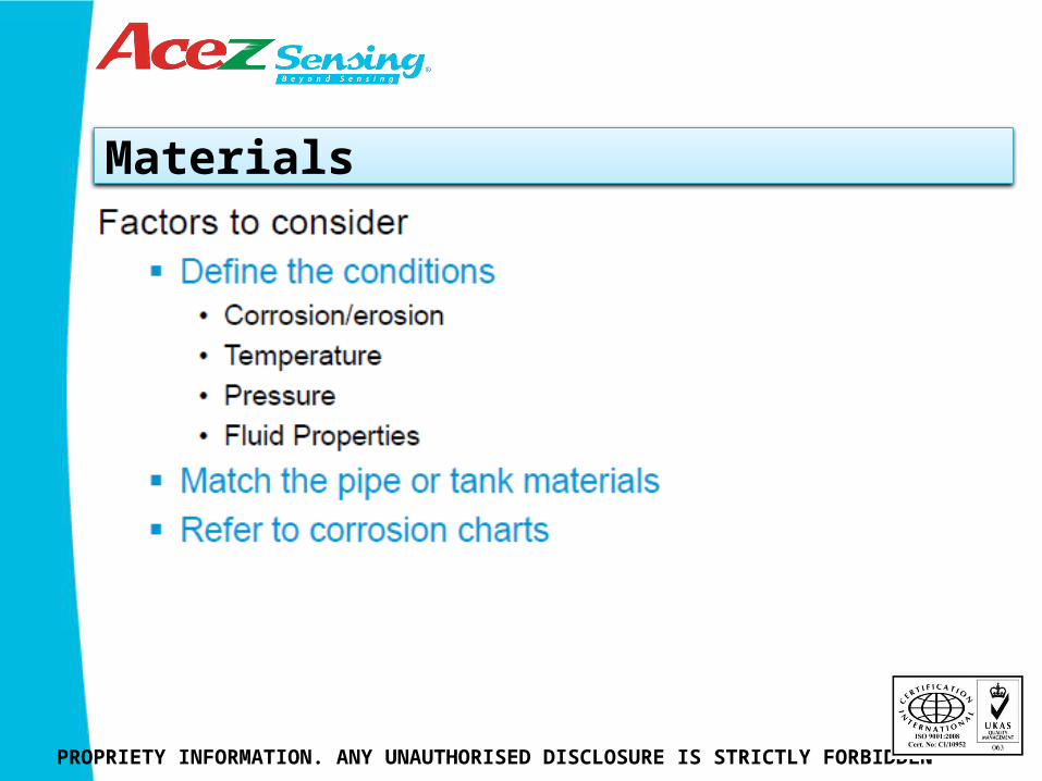
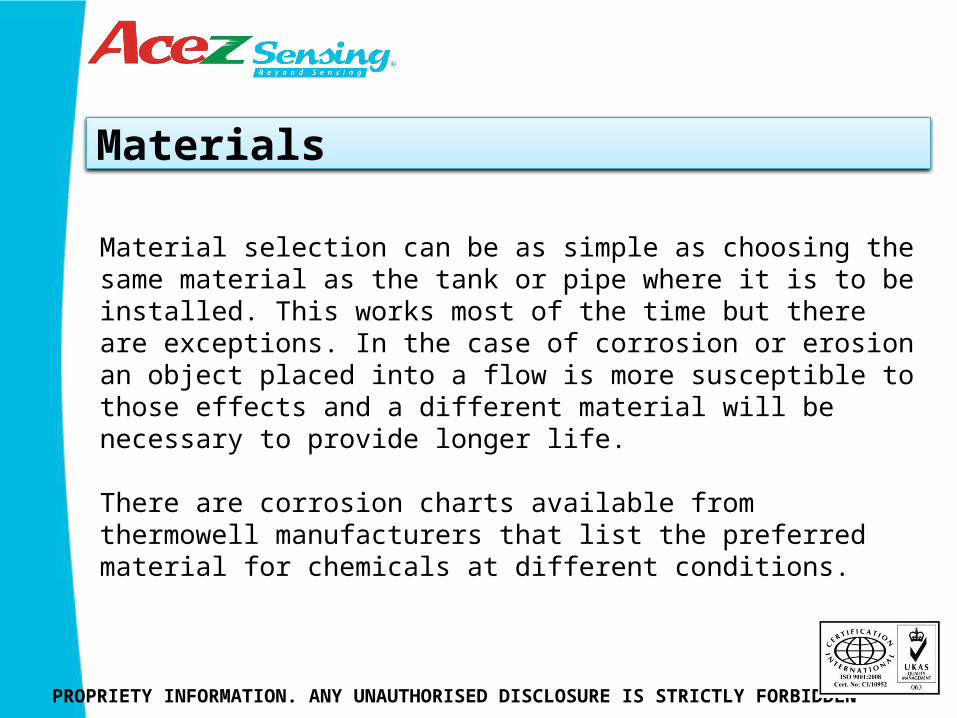
Material selection can be as simple as choosing the same material as the tank or pipe where it is to be installed. This works most of the time but there are exceptions. In the case of corrosion or erosion an object placed into a flow is more susceptible to those effects and a different material will be necessary to provide longer life.
There are corrosion charts available from thermowell manufacturers that list the preferred material for chemicals at different conditions.
Materials Corrosion
PROPRIETY INFORMATION. ANY UNAUTHORISED DISCLOSURE IS STRICTLY FORBIDDEN
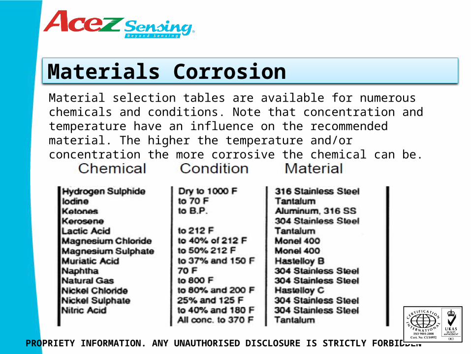
Material selection tables are available for numerous chemicals and conditions. Note that concentration and temperature have an influence on the recommended material. The higher the temperature and/or concentration the more corrosive the chemical can be.

Corrosion
PROPRIETY INFORMATION. ANY UNAUTHORISED DISCLOSURE IS STRICTLY FORBIDDEN
Choosing the wrong material can result in failure of the well. Here the tip has corroded away and allowed the process fluid to leak inside the well.
Corrosion
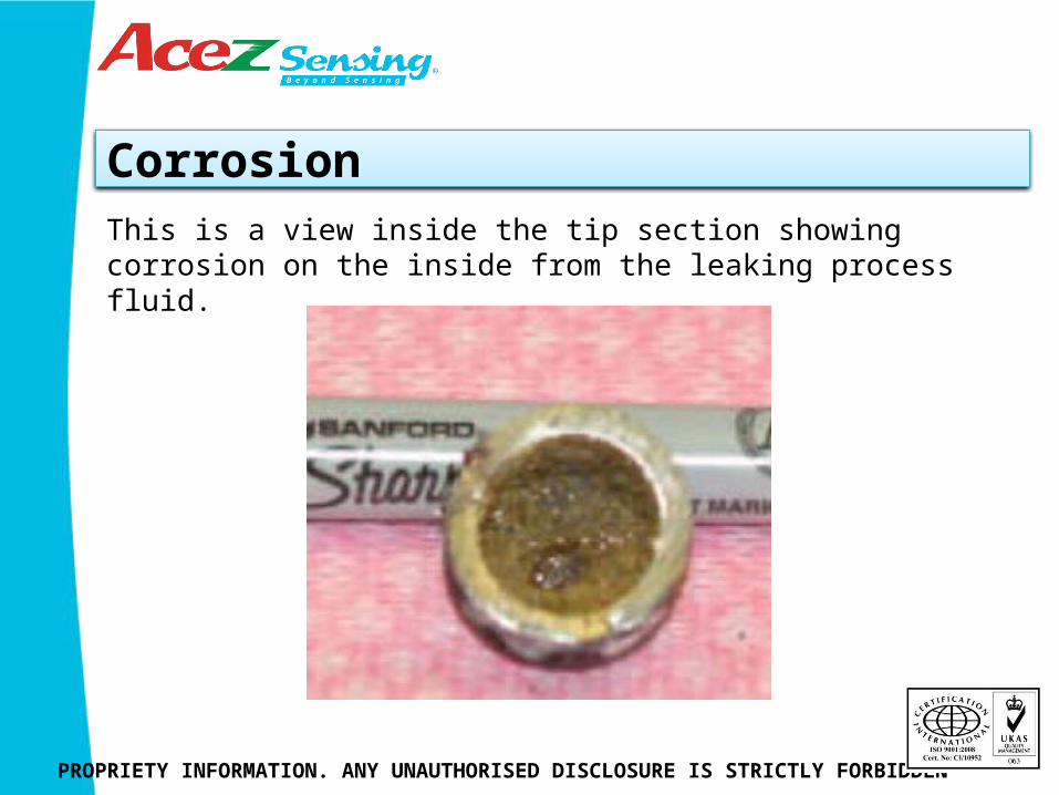
PROPRIETY INFORMATION. ANY UNAUTHORISED DISCLOSURE IS STRICTLY FORBIDDEN
This is a view inside the tip section showing corrosion on the inside from the leaking process fluid.
Materials- Erosion
PROPRIETY INFORMATION. ANY UNAUTHORISED DISCLOSURE IS STRICTLY FORBIDDEN
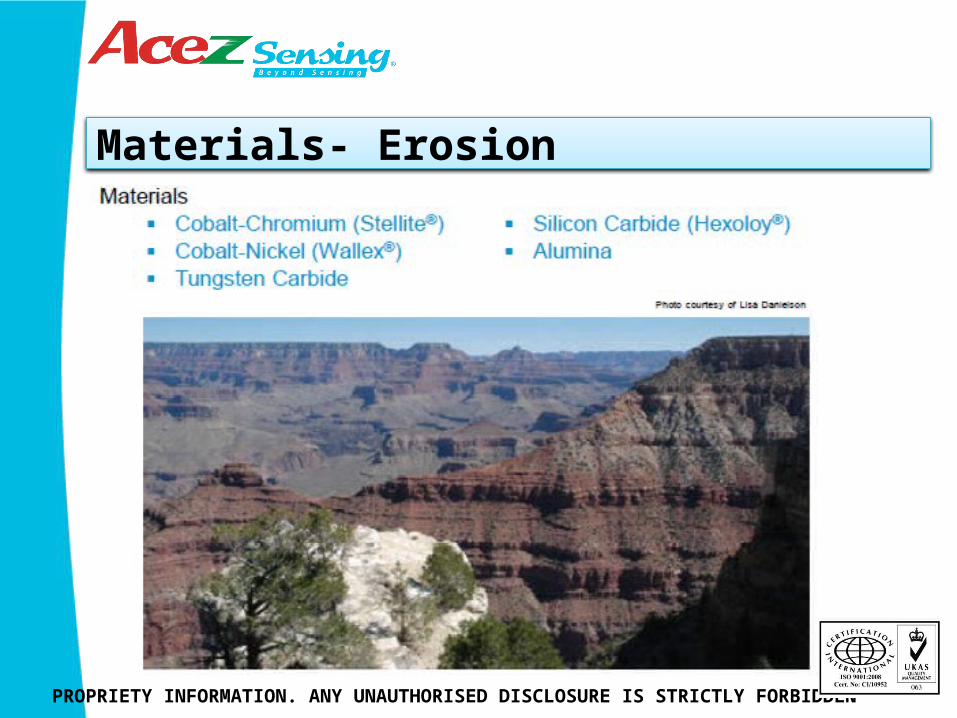
Particles suspended in a fluid or powdered materials can cause erosion of the well over time. There are several materials available to slow down the erosion. Most are hard materials that are applied through a welding or spraying process. Sometimes just picking the correct thermowell material is sufficient to minimize the erosion affects.
Materials- Erosion
PROPRIETY INFORMATION. ANY UNAUTHORISED DISCLOSURE IS STRICTLY FORBIDDEN
PROPRIETY INFORMATION. ANY UNAUTHORISED DISCLOSURE IS STRICTLY FORBIDDEN
Materials -Selection
Materials -Selection
PROPRIETY INFORMATION. ANY UNAUTHORISED DISCLOSURE IS STRICTLY FORBIDDEN
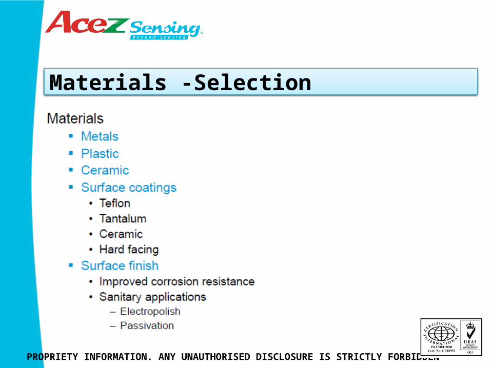
A variety of materials can be used to construct thermowells. Surface coatings can be used to improve corrosion and erosion resistance. Plastics such as Teflon are highly corrosion resistant and ceramics offer high temperature capabilities and can be a good choice for erosive applications.
Tantalum is used for acid resistance and can be applied as a sleeve or it can be bonded to the surface of nearly any thermowell style. Improving the surface finish will increase corrosion resistance and make it easier to clean. Fewer ridges and crevices means a smaller surface area for the corrodent to attack. Electropolishing or passivating the surface further increases corrosion resistance.
Materials
PROPRIETY INFORMATION. ANY UNAUTHORISED DISCLOSURE IS STRICTLY FORBIDDEN
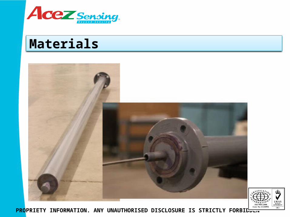
Sometimes less expensive materials turn out to be the best choice. Originally a Teflon plated metal well was used for monitoring the temperature of an acidic waste product. Teflon plating is easily damaged (think of your frying pan) and the acid quickly ate away the metal well causing it to leak. The solution was to use standard 3” PVC pipe to construct the well which was about 10 fts long and attached with a flange connection. An internal well was made with ½” PVC to house the temperature sensor allowing it to stick out a couple inches for better time response.
Materials
PROPRIETY INFORMATION. ANY UNAUTHORISED DISCLOSURE IS STRICTLY FORBIDDEN

Positive Material Identification (PMI)
PROPRIETY INFORMATION. ANY UNAUTHORISED DISCLOSURE IS STRICTLY FORBIDDEN
Positive Material Identification (PMI)
PROPRIETY INFORMATION. ANY UNAUTHORISED DISCLOSURE IS STRICTLY FORBIDDEN
Positive Material Identification (PMI) refers to the identification and analysis of various metal alloys based on their chemical composition in non-destructive testing (NDT). Measurement results are shown in the form of elemental concentration in percentage or by specific alloy name such as SS316L or Inconel 625. PMI is a field‐testing method made possible by the portability of most PMI analysers. These instruments also can be used in the laboratory The X‐Ray Fluorescence Technique XRF XRF instruments work by exposing a sample to a beam of X‐rays. The atoms of the sample absorb energy from the X‐rays, become temporarily excited and then emit secondary X‐rays. Each chemical element emits X‐rays at a unique energy. By measuring intensity and characteristic energy of the emitted X‐rays, an XRF analyser can provide qualitative and quantitative analysis regarding the composition of the material being tested.
Performance
PROPRIETY INFORMATION. ANY UNAUTHORISED DISCLOSURE IS STRICTLY FORBIDDEN
Performance
PROPRIETY INFORMATION. ANY UNAUTHORISED DISCLOSURE IS STRICTLY FORBIDDEN
Measurement accuracy can be adversely affected by a thermowell unless a few precautions are taken. Wake frequency and strength calculations are probably the most important. These calculations will tell you how long the well can be immersed into your process based on the flow conditions (more on this later). This has to be balanced with the accuracy needs of the sensor to be immersed sufficiently to prevent stem conduction or immersion error. Finally, time response is slower with the addition of a thermowell and for processes that change temperature rapidly this can be a significant error source.
ASME PTC 19.3 TW-2010
PROPRIETY INFORMATION. ANY UNAUTHORISED DISCLOSURE IS STRICTLY FORBIDDEN
Application ASME PTC 19.3 TW -2010The long awaited PTC 19.3 TW-2010 is a completely new standard that establishes the practical design considerations for thermowell installations in power and process piping. This code is an expanded version of the thermowell section contained in the PTC 19.3-1974, and incorporates the latest theory in the areas of natural frequency, Strouhal frequency, in-line resonance and stress evaluation. ASME responded to changing industry demands for a more comprehensive set of thermowell evaluations. Key enhancements over the 1974 edition include:
• Expanded coverage for thermowellgeometry• Natural frequency correction factors for mounting compliance, added fluid mass, and sensor mass• Consideration for partial shielding from flow• Intrinsic thermowell damping;• Steady state and dynamic stress evaluations• Improved allowable fatigue limit definition.

ASME PTC 19.3 TW-2010
PROPRIETY INFORMATION. ANY UNAUTHORISED DISCLOSURE IS STRICTLY FORBIDDEN
The new release of the thermowell section of the Power Test Code incorporate the latest theory for wake frequency and strength calculations . If you’re a piping designer all this probably means a lot to you. For someone selecting a thermowell it may be a little like learning how to build a chainsaw to cut down a tree. Interesting but not really necessary. Your thermowell supplier will provide the calculations based your process conditions and desired thermowell configuration. You need to know that you want the calculations done to the new 2010 version of the standard.

Von Kármán Vortex
PROPRIETY INFORMATION. ANY UNAUTHORISED DISCLOSURE IS STRICTLY FORBIDDEN
When a cylindrical object is placed in a flow there is a disturbance created on the downstream side that oscillates back and forth. The frequency of the oscillation increases as the flow rate increases. If the resonant frequency of the thermowell matches the frequency of the vortices the well will start to vibrate and will first damage the RTD and then the well will fail. There are a lot of good illustrations of this phenomena on the internet. A search for von karman or wake frequency will return several.
Thermowell Selection
PROPRIETY INFORMATION. ANY UNAUTHORISED DISCLOSURE IS STRICTLY FORBIDDEN
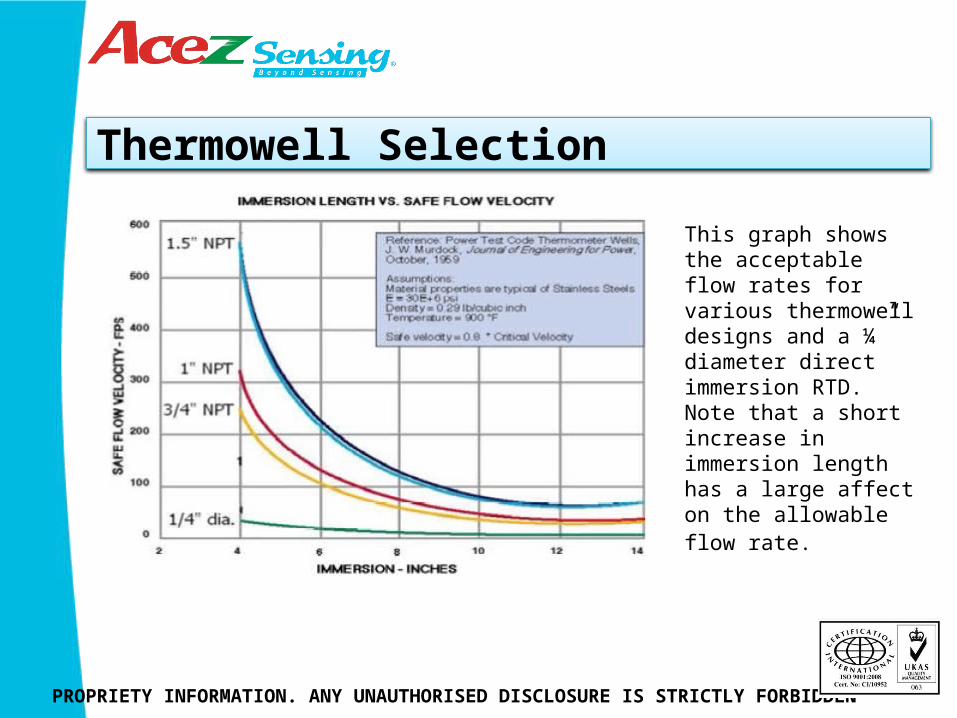
This graph shows the acceptable flow rates for various thermowell designs and a ¼” diameter direct immersion RTD. Note that a short increase in immersion length has a large affect on the allowable flow rate.

Information Required
PROPRIETY INFORMATION. ANY UNAUTHORISED DISCLOSURE IS STRICTLY FORBIDDEN
This is typical of the information that is needed to perform the calculations.
Stress Crack
PROPRIETY INFORMATION. ANY UNAUTHORISED DISCLOSURE IS STRICTLY FORBIDDEN
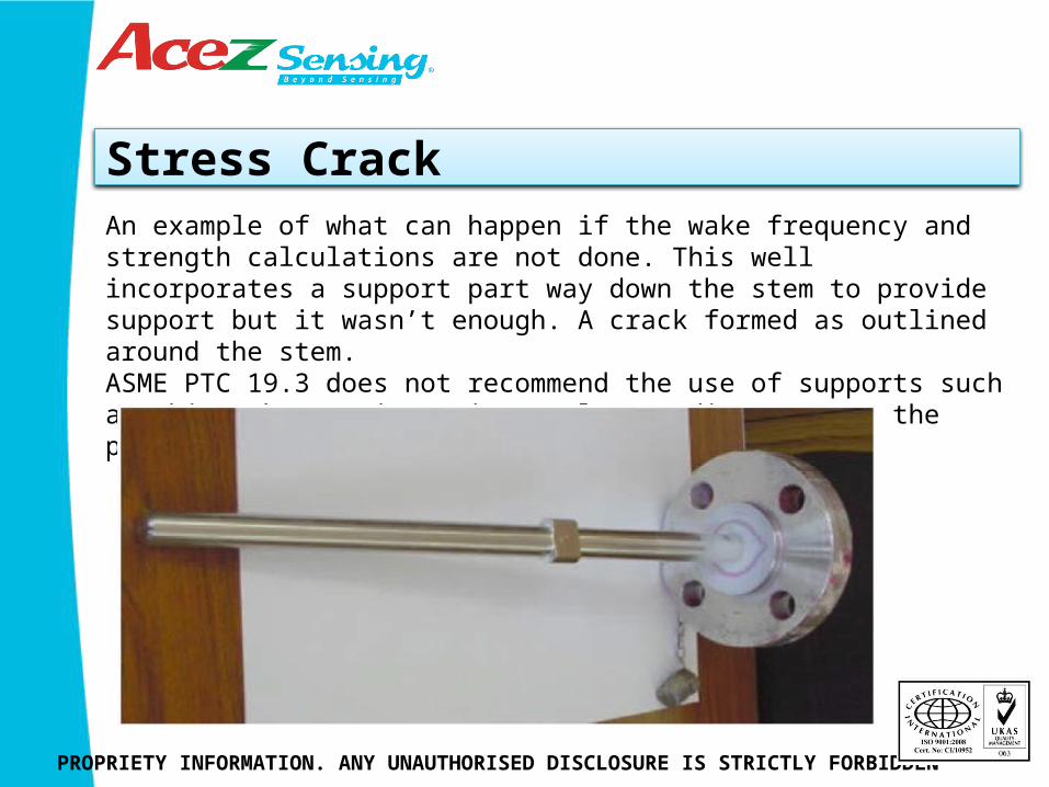
An example of what can happen if the wake frequency and strength calculations are not done. This well incorporates a support part way down the stem to provide support but it wasn’t enough. A crack formed as outlined around the stem. ASME PTC 19.3 does not recommend the use of supports such as this. Shorter immersion or larger diameter are the preferred solutions.
Stress Crack
PROPRIETY INFORMATION. ANY UNAUTHORISED DISCLOSURE IS STRICTLY FORBIDDEN
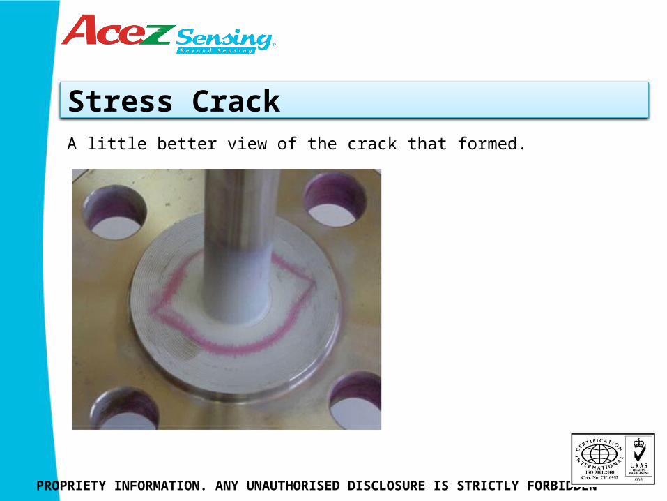
A little better view of the crack that formed.
Immersion length
PROPRIETY INFORMATION. ANY UNAUTHORISED DISCLOSURE IS STRICTLY FORBIDDEN
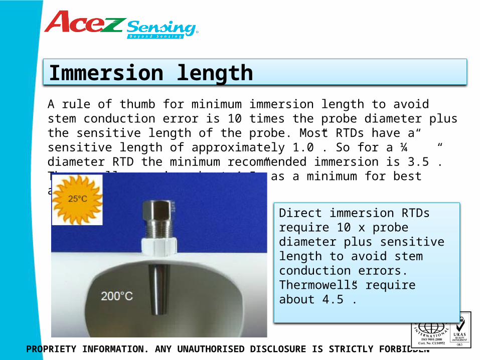
Direct immersion RTDs require 10 x probe diameter plus sensitive length to avoid stem conduction errors. Thermowells require about 4.5”.
A rule of thumb for minimum immersion length to avoid stem conduction error is 10 times the probe diameter plus the sensitive length of the probe. Most RTDs have a sensitive length of approximately 1.0”. So for a ¼” diameter RTD the minimum recommended immersion is 3.5”. Thermowells require about 4.5” as a minimum for best accuracy.
Immersion Error
PROPRIETY INFORMATION. ANY UNAUTHORISED DISCLOSURE IS STRICTLY FORBIDDEN
Immersion Error
PROPRIETY INFORMATION. ANY UNAUTHORISED DISCLOSURE IS STRICTLY FORBIDDEN
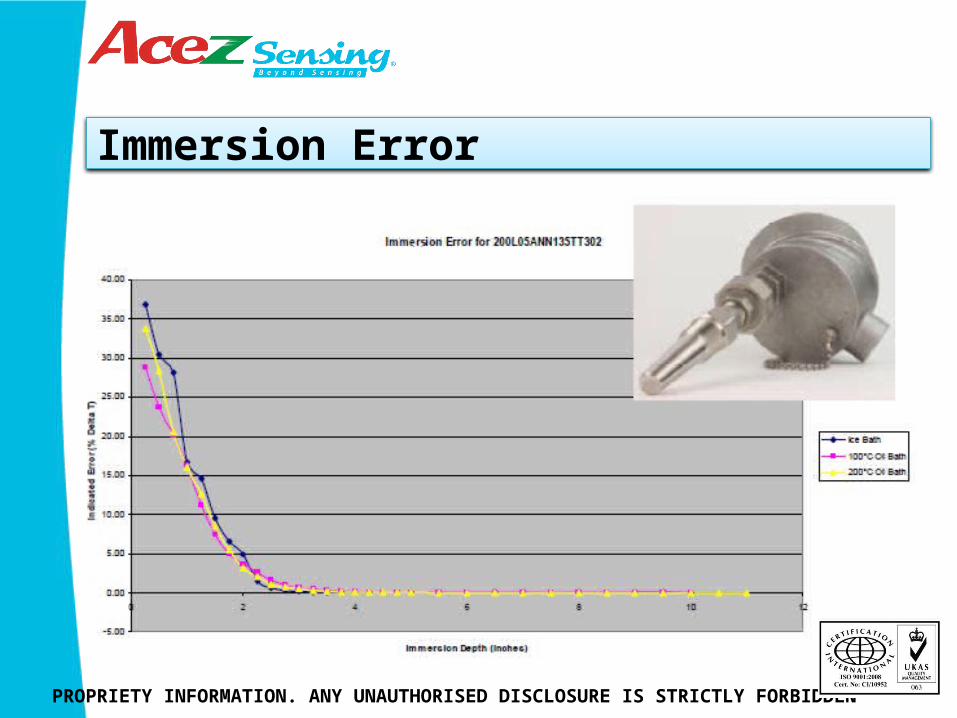
A thermowell/RTD assembly was immersed in a bath to determine the stem conduction at various depths. At 4.5 inches most of the error has disappeared. As you can see the error is mostly independent of the bath temperature used. The error is expressed as a percentage of the delta T between ambient and process conditions.
Specialty- Elbow Wells
PROPRIETY INFORMATION. ANY UNAUTHORISED DISCLOSURE IS STRICTLY FORBIDDEN
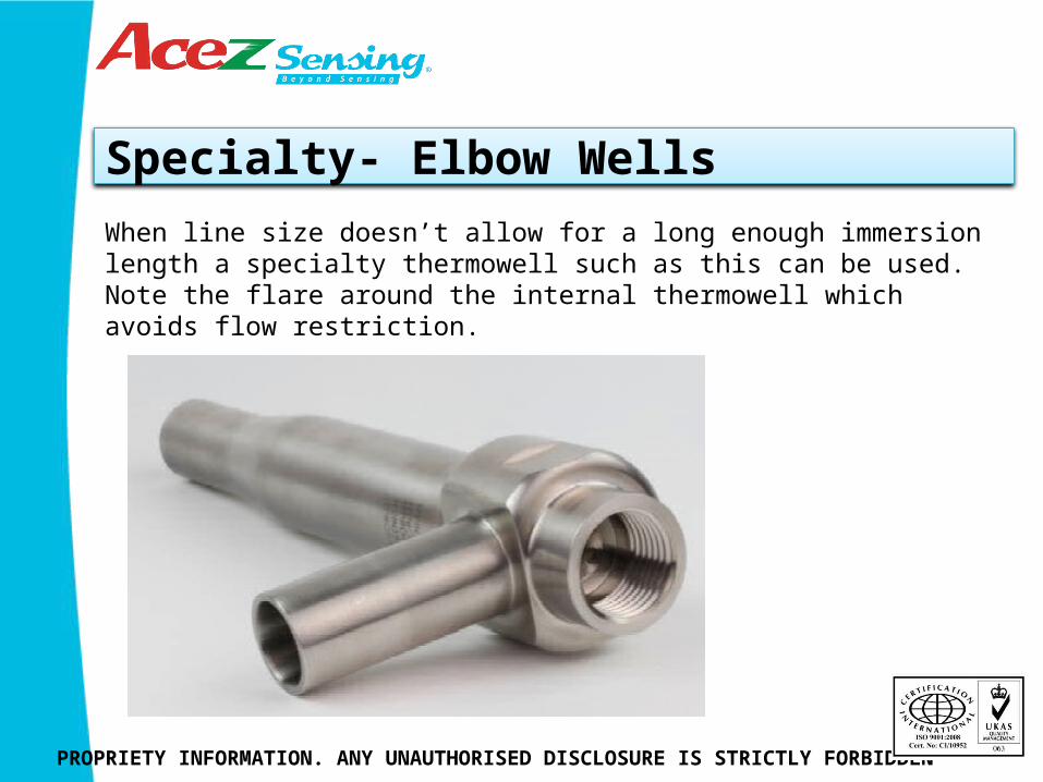
When line size doesn’t allow for a long enough immersion length a specialty thermowell such as this can be used. Note the flare around the internal thermowell which avoids flow restriction.
Elbow Well Drawing
PROPRIETY INFORMATION. ANY UNAUTHORISED DISCLOSURE IS STRICTLY FORBIDDEN
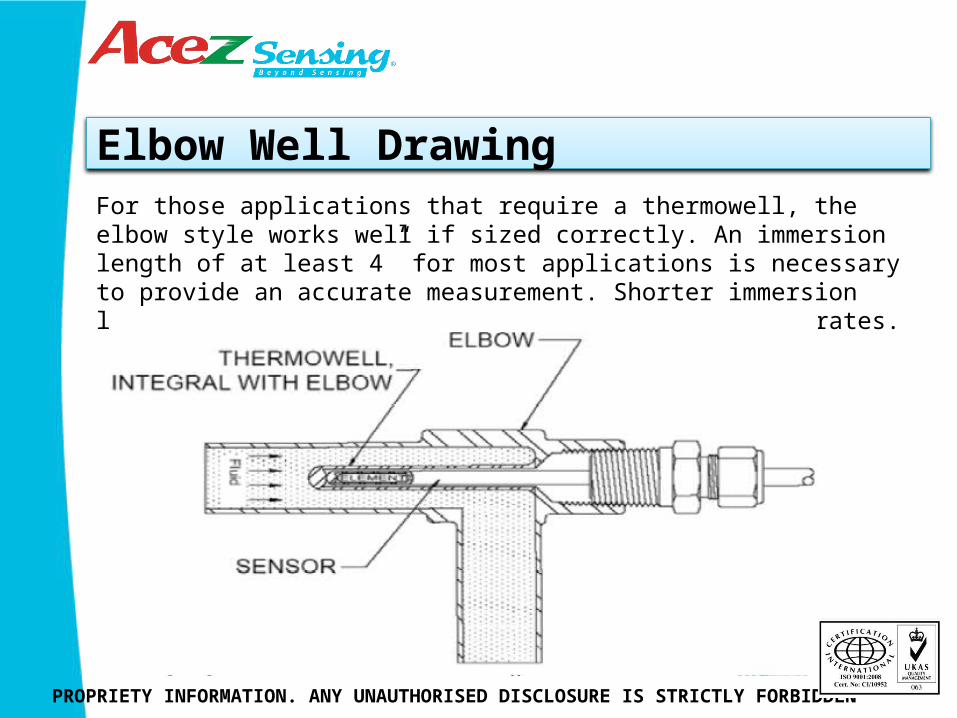
For those applications that require a thermowell, the elbow style works well if sized correctly. An immersion length of at least 4” for most applications is necessary to provide an accurate measurement. Shorter immersion lengths may work for some process fluids and flow rates.
Installation in a Tee
PROPRIETY INFORMATION. ANY UNAUTHORISED DISCLOSURE IS STRICTLY FORBIDDEN
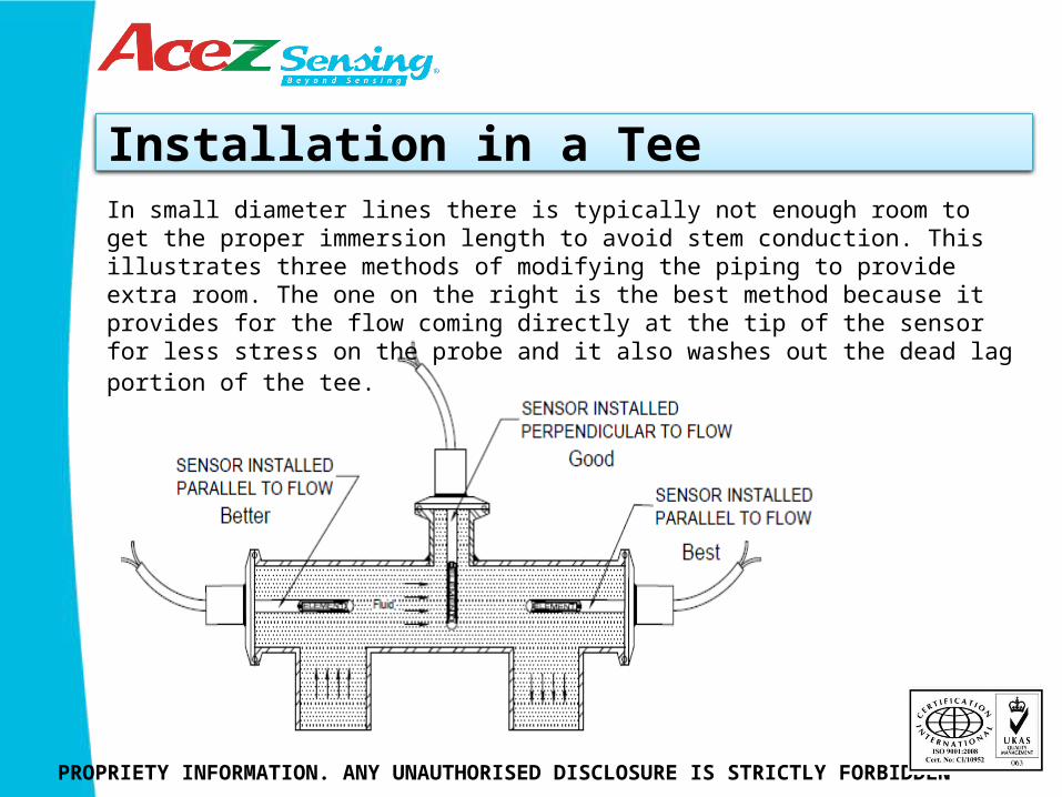
In small diameter lines there is typically not enough room to get the proper immersion length to avoid stem conduction. This illustrates three methods of modifying the piping to provide extra room. The one on the right is the best method because it provides for the flow coming directly at the tip of the sensor for less stress on the probe and it also washes out the dead lag portion of the tee.

Anti-Immersion?
PROPRIETY INFORMATION. ANY UNAUTHORISED DISCLOSURE IS STRICTLY FORBIDDEN
Another installation method which we don’t recommend. There’s probably a joke behind this such as “it’s for room air temperature” or it makes a nice “hand hold”. Likely just the 2nd shift crew having fun with the 1st shift crew. In any case, a reminder to always double‐check your installation.
Performance- Time Constant
PROPRIETY INFORMATION. ANY UNAUTHORISED DISCLOSURE IS STRICTLY FORBIDDEN
Time Constant is defined as the time it takes for the sensor to indicate 63.2% of a step change in temperature in water moving at 3 fps.
Adding heat transfer paste cuts these times nearly in half.
Specialty- Fast Response Tip
PROPRIETY INFORMATION. ANY UNAUTHORISED DISCLOSURE IS STRICTLY FORBIDDEN
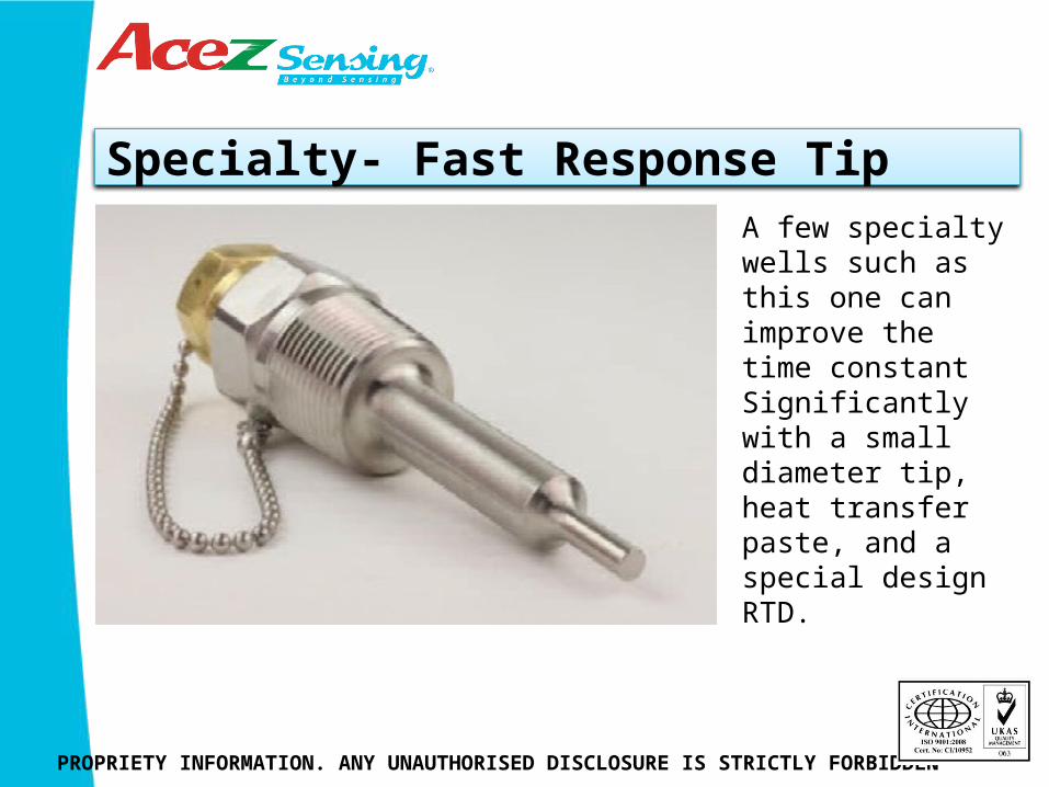
A few specialty wells such as this one can improve the time constant Significantly with a small diameter tip, heat transfer paste, and a special design RTD.
Specialty-Flow-Through Design
PROPRIETY INFORMATION. ANY UNAUTHORISED DISCLOSURE IS STRICTLY FORBIDDEN
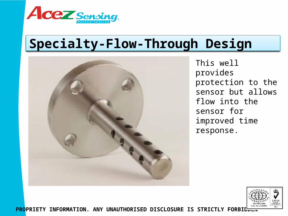
This well provides protection to the sensor but allows flow into the sensor for improved time response.
Specialty-Large Diameter Elbow
PROPRIETY INFORMATION. ANY UNAUTHORISED DISCLOSURE IS STRICTLY FORBIDDEN
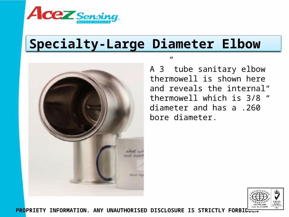
A 3” tube sanitary elbow thermowell is shown here and reveals the internal thermowell which is 3/8” diameter and has a .260” bore diameter.
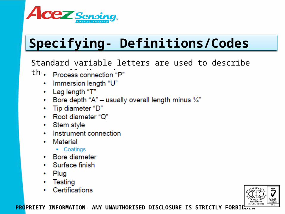
Specifying- Definitions/Codes
PROPRIETY INFORMATION. ANY UNAUTHORISED DISCLOSURE IS STRICTLY FORBIDDEN
Standard variable letters are used to describe thermowell dimensions.

Specifying- Typical Drawing
PROPRIETY INFORMATION. ANY UNAUTHORISED DISCLOSURE IS STRICTLY FORBIDDEN
Of these the immersion length U and the bore depth A are most commonly used for specifying the length of the sensor.
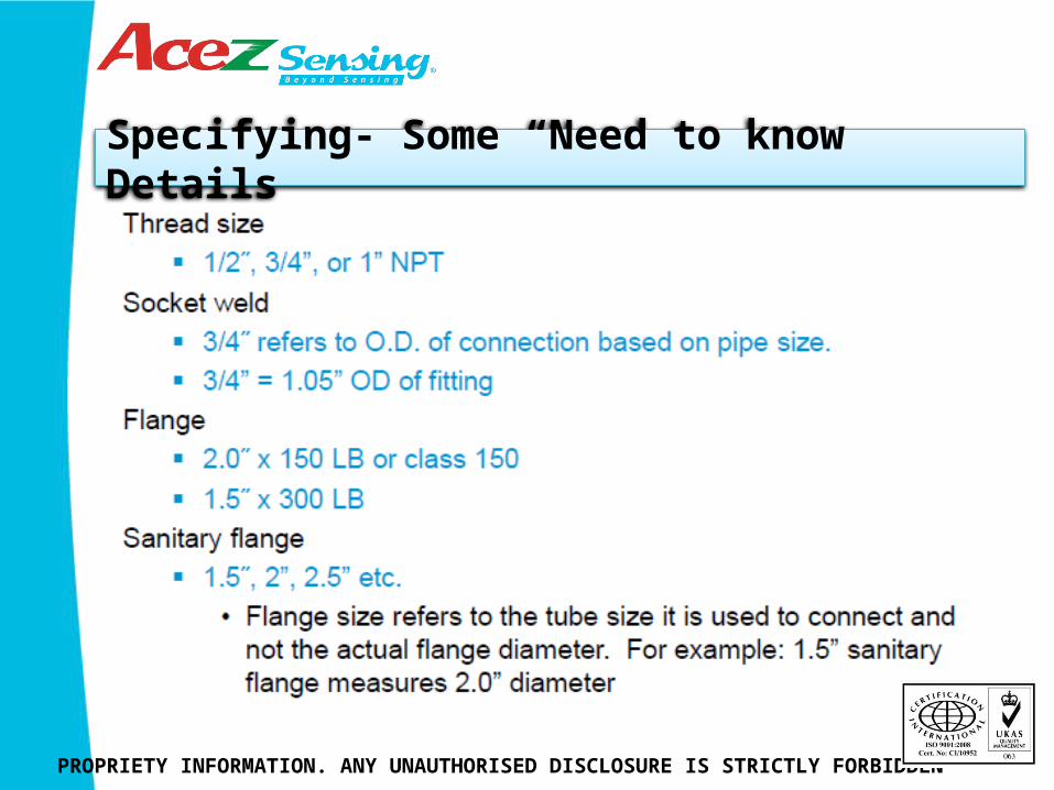
Specifying- Some “Need to know” Details
PROPRIETY INFORMATION. ANY UNAUTHORISED DISCLOSURE IS STRICTLY FORBIDDEN
Some knowledge of the various types of process connections is required to choose the correct size. Threaded connections are NPT and fairly straight forward. Flange connection sizes refer to the size pipe or tube which they connect.
Specifying- Some “Need to know Details
PROPRIETY INFORMATION. ANY UNAUTHORISED DISCLOSURE IS STRICTLY FORBIDDEN
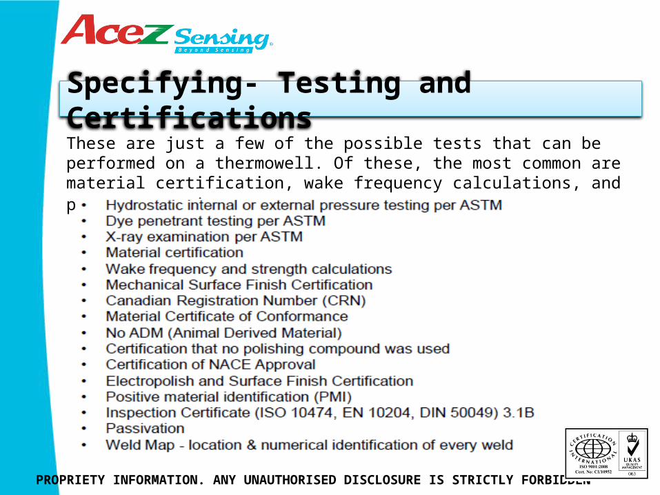
Specifying- Testing and Certifications
PROPRIETY INFORMATION. ANY UNAUTHORISED DISCLOSURE IS STRICTLY FORBIDDEN
These are just a few of the possible tests that can be performed on a thermowell. Of these, the most common are material certification, wake frequency calculations, and pressure testing.
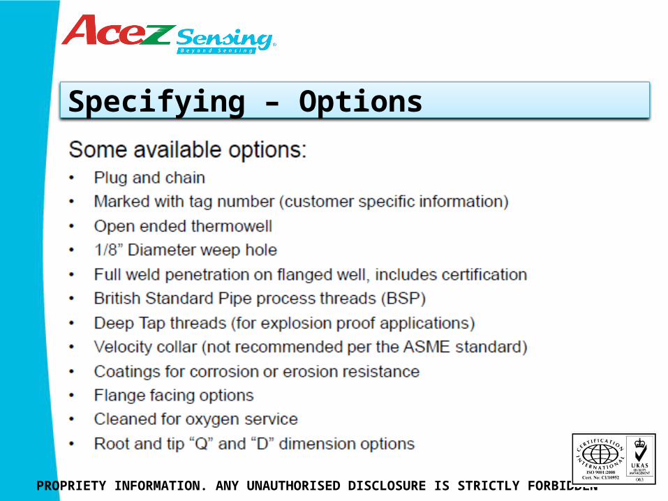
Specifying – Options
PROPRIETY INFORMATION. ANY UNAUTHORISED DISCLOSURE IS STRICTLY FORBIDDEN
An ounce of prevention
PROPRIETY INFORMATION. ANY UNAUTHORISED DISCLOSURE IS STRICTLY FORBIDDEN
Thermowells typically need only minimal maintenance, keeping them clean inside and out is usually all that is required. Heat transfer paste should be renewed if the sensor is removed for calibration or replacement.
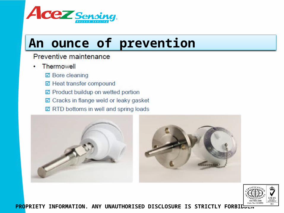
An ounce of prevention
PROPRIETY INFORMATION. ANY UNAUTHORISED DISCLOSURE IS STRICTLY FORBIDDEN
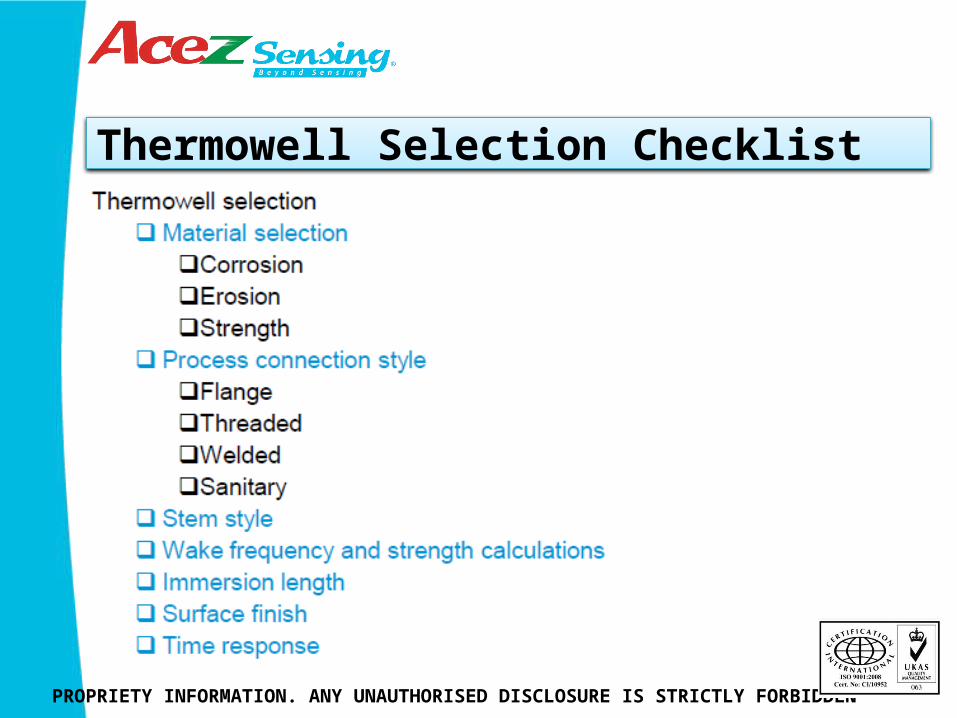
Thermowell Selection Checklist
PROPRIETY INFORMATION. ANY UNAUTHORISED DISCLOSURE IS STRICTLY FORBIDDEN
Summary
PROPRIETY INFORMATION. ANY UNAUTHORISED DISCLOSURE IS STRICTLY FORBIDDEN

Thank you for attending
PROPRIETY INFORMATION. ANY UNAUTHORISED DISCLOSURE IS STRICTLY FORBIDDEN


