UNIVERSIDADE DE LISBOA INSTITUTO SUPERIOR TÉCNICO Integrating Enterprise Architecture and IT Service Management NELSON FERNANDO PINHEIRO DA GAMA Supervisor: Doctor MIGUEL LEITÃO BIGNOLAS MIRA DA SILVA Thesis approved in public session to obtain the PhD Degree in Information Systems and Computer Engineering Jury final classification: Pass with Merit Jury Chairperson: CHAIRMAN OF THE IST SCIENTIFIC BOARD Members of the Committee: Doctor JOÃO PAULO ANDRADE ALMEIDA Doctor FERNANDO MANUEL DA COSTA BRITO E ABREU Doctor JOSÉ LUIS BRINQUETE BORBINHA Doctor MIGUEL LEITÃO BIGNOLAS MIRA DA SILVA 2014
Transcript
UNIVERSIDADE DE LISBOA
INSTITUTO SUPERIOR TÉCNICO
Integrating Enterprise Architecture and
IT Service Management
NELSON FERNANDO PINHEIRO DA GAMA
Supervisor: Doctor MIGUEL LEITÃO BIGNOLAS MIRA DA SILVA
Thesis approved in public session to obtain the PhD Degree in
Information Systems and Computer Engineering
Jury final classification: Pass with Merit
Jury
Chairperson: CHAIRMAN OF THE IST SCIENTIFIC BOARD
Members of the Committee: Doctor JOÃO PAULO ANDRADE ALMEIDA Doctor FERNANDO MANUEL DA COSTA BRITO E ABREU Doctor JOSÉ LUIS BRINQUETE BORBINHA Doctor MIGUEL LEITÃO BIGNOLAS MIRA DA SILVA
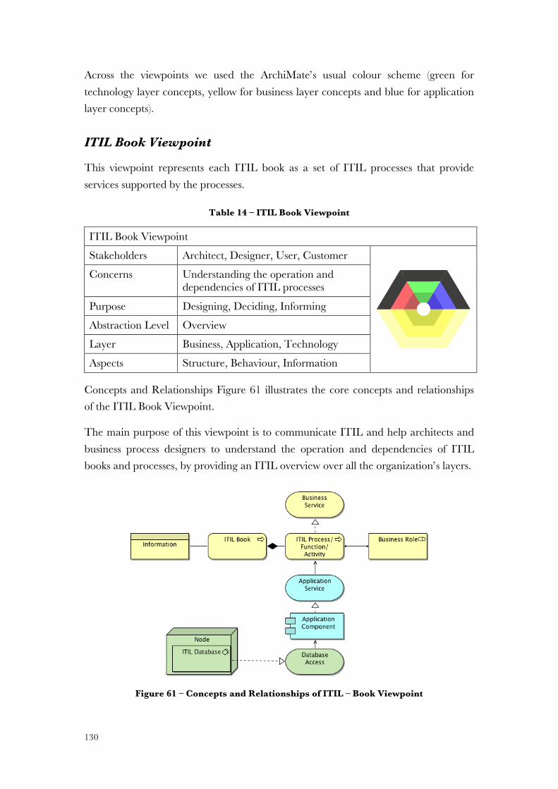
2014
UNIVERSIDADE DE LISBOA
INSTITUTO SUPERIOR TÉCNICO
Integrating Enterprise Architecture and
IT Service Management
NELSON FERNANDO PINHEIRO DA GAMA
Supervisor: Doctor MIGUEL LEITÃO BIGNOLAS MIRA DA SILVA
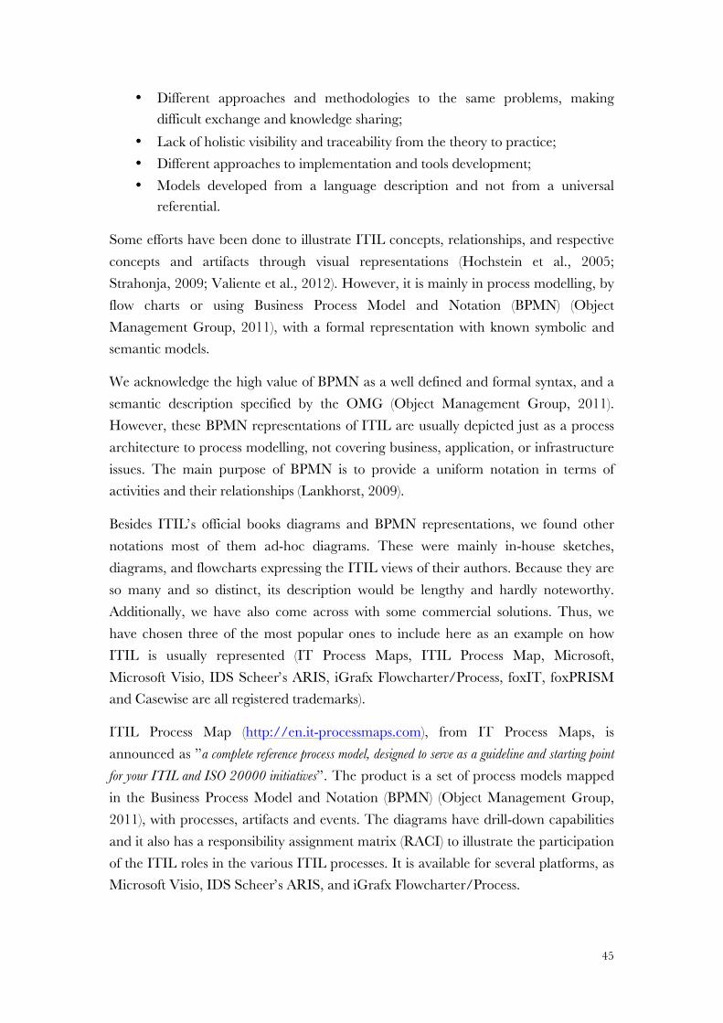
Thesis approved in public session to obtain the PhD Degree in Engenharia Informática e de Computadores
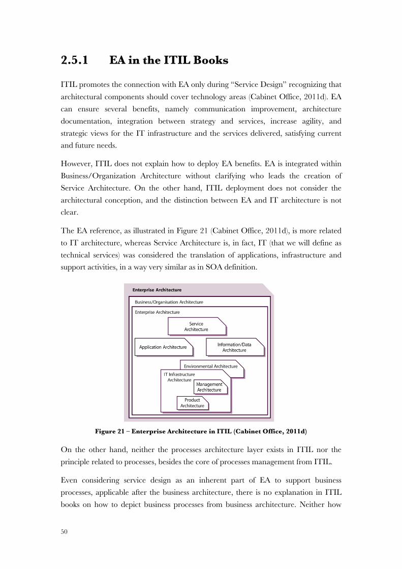
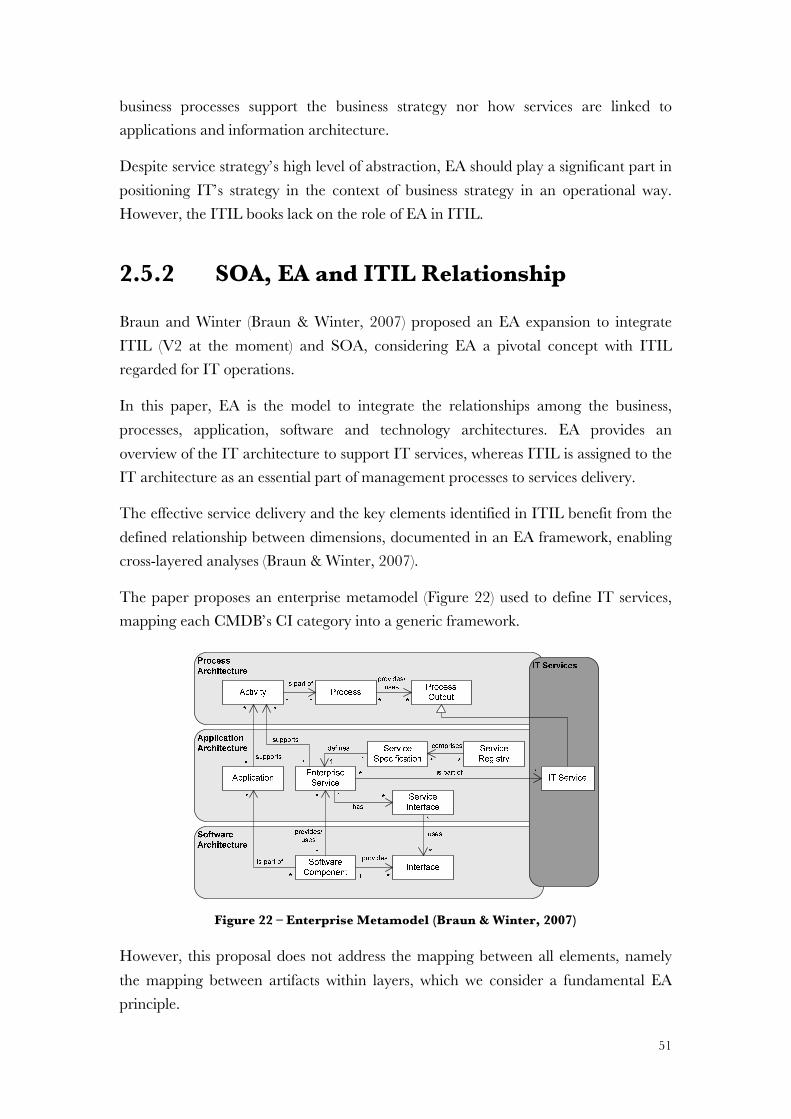
Jury final classification: Pass with Merit
Jury
Chairperson: CHAIRMAN OF THE IST SCIENTIFIC BOARD Members of the Committee:
Doctor JOÃO PAULO ANDRADE ALMEIDA, Professor Associado da Universidade Federal do Espírito Santo, Brasil Doctor FERNANDO MANUEL DA COSTA BRITO E ABREU, Professor Associado do Instituto Superior de Ciências do Trabalho e da Empresa – Instituto Universitário de Lisboa Doctor JOSÉ LUÍS BRINQUETE BORBINHA, Professor Associado do Instituto Superior Técnico, da Universidade de Lisboa Doctor MIGUEL LEITÃO BIGNOLAS MIRA DA SILVA, Professor Auxiliar do Instituto Superior Técnico, da Universidade de Lisboa
2014
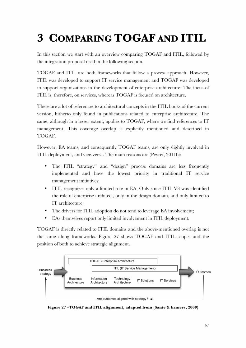
vii
ABSTRACT Different efforts have been developed focusing on the alignment between organizations’ concepts. From these initiatives, two have had outstanding relevance: Enterprise Architecture (EA) and IT Service Management (ITSM). However, these two approaches are often used complementarily and simultaneously. The integration of both approaches avoids the need to adopt different frameworks covering overlapping topics.
In the literature we found few scientific papers regarding this integration. Although some have tried to integrate these two approaches, we have not identified a proposal satisfying our integration requirements. The lack of integration proposals increases the problem’s relevance.
This dissertation proposes the integration between EA and ITSM through the integration of two of the best known and used frameworks, respectively TOGAF and ITIL. We analysed the relationship among the concepts from TOGAF and ITIL identifying a common ontology. We identified similarities between both approaches and mapped the integration using ArchiMate as a mutual modelling language to model ITIL, defining an ITIL metamodel and an ArchiMate specialization.
Based on Design Science Research methodology we demonstrated and evaluated our research proposal using a set of ITIL models and applying the proposal in a field study inside a public organization.
ix
RESUMO Diferentes esforços têm sido desenvolvidos visando alinhar as diferentes dimensões organizacionais. Dessas iniciativas, duas têm tido maior relevo: Enterprise Architecture (EA) e IT Service Management (ITSM). Contudo, estas abordagens são frequentemente usadas complementarmente e em simultâneo. A integração destas abordagens, num referencial comum, evita a necessidade de adoptar diferentes quadros de referência cobrindo em sobreposição os mesmos tópicos.
Da revisão bibliográfica constatámos que existem poucas referências científicas em matéria de integração e as que existem não satisfazem os nossos requisitos de integração. A ausência de propostas de integração aumenta a relevância do problema.
Esta dissertação propõe a integração das abordagens EA e ITSM através da integração de dois dos quadros de referência de maior relevo, respetivamente, TOGAF e ITIL. Analisámos o relacionamento entre conceitos TOGAF e ITIL identificando uma ontologia comum. Identificámos semelhanças entre ambas as abordagens e mapeámos a integração usando a linguagem ArchiMate como uma linguagem de modelação mútua para modelar o ITIL, definindo um metamodelo para o ITIL e especializando a linguagem ArchiMate.
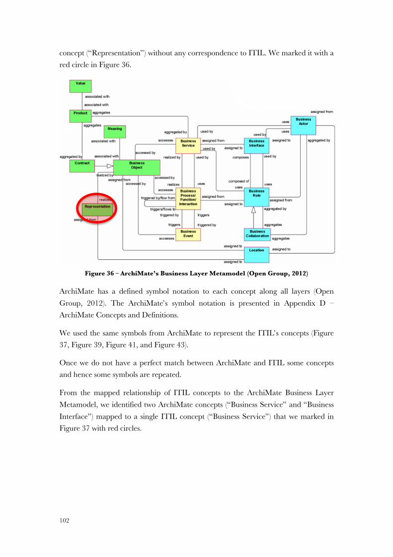
Baseada na metodologia Design Science Research, demonstrámos e avaliámos a nossa proposta através de um conjunto de modelos ITIL e aplicando a proposta como caso prático numa organização pública.
xi
ACKNOWLEDGEMENTS First of all, I am grateful to Professor Miguel Mira da Silva for supporting me through his encouragement and guidance, and for allowing me to develop this work, opening the doors to a new world of knowledge.
My thanks also go to Professors José Manuel Tribolet, Pedro Sousa, Pedro Barros, José Borbinha, Alberto Silva and Artur Ferreira da Silva, who, sometimes without even realizing it, encouraged me in the most crucial part of my PhD.
My thanks to Professors Fernando Brito e Abreu and João Paulo Almeida for their constructive criticism, decisive for the outcome of the dissertation's final document.
My grateful thanks for the support of my superiors in the Navy and the Ministry of Defence who trusted, believed and allowed me to develop my research and apply it in practice.
I would also like to thank my family, colleagues and friends who always encouraged me to go forward and to Rita for her valuable help, immense patience and friendship.
Thanks to my in-laws, who always helped me with time management and support.
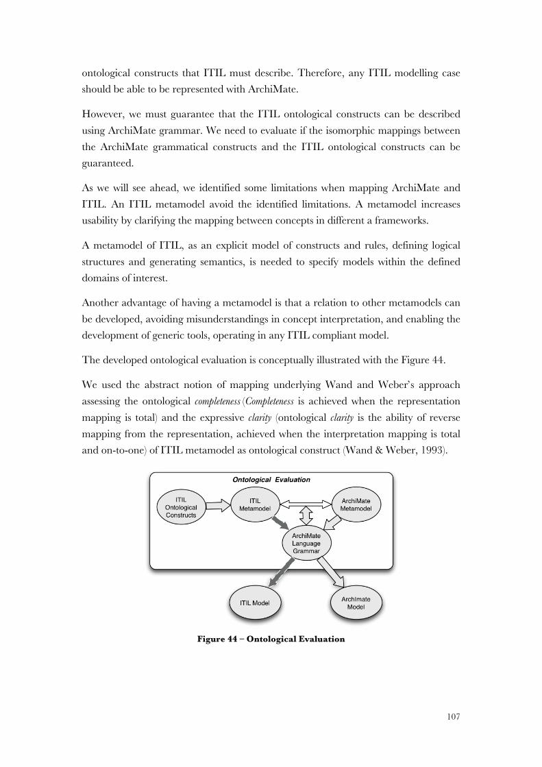
Thanks to my parents, my best friends but also the best parents anyone could have. Thanks for always supporting my decisions (not always wise), for your patience, and for always encouraging and helping me to be a better person.
My special thanks go to my sister, my biggest fan and my unconditional darling. Thanks sis, for being as you are.
I also want to thank my two “forces of nature”, my dear sons Simão and Afonso, for still loving your daddy, despite so many absences and hours of play lost.
Finally, a particularly distinctive and meaningful thank you to Sandra, my wife, my friend, my inspiration, my faithful companion and confidant. Thank you for your constant patience and support. Without you none of this would have been possible…
xiii
AGRADECIMENTOS Primeiramente, o meu agradecimento ao Professor Miguel Mira da Silva pelo seu apoio, encorajamento, orientação e por me ter permitido desenvolver este trabalho, abrindo-me as portas a um novo mundo do conhecimento.
Os meus agradecimentos também aos Professores José Manuel Tribolet, Pedro Sousa, Pedro Barros, José Borbinha, Alberto Silva e Artur Ferreira da Silva, os quais, por vezes sem se aperceberem foram determinantes pelo seu encorajamento na parte mais crucial do meu percurso académico.
Agradeço também aos Professores Fernando Brito e Abreu e João Paulo Almeida pela sua critica construtiva determinante para o resultado final do documento de dissertação.
O meu reconhecido agradecimento pelo apoio dos meus superiores hierárquicos na Marinha Portuguesa e no Ministério da Defesa, que acreditaram no meu trabalho e me permitiram desenvolver a sua aplicação.
Aos meus familiares, amigos, camaradas e colegas, que sempre me incentivaram e apoiaram. Entre eles estão os amigos de sempre e para sempre. Um especial agradecimento à Rita pela sua valiosa ajuda, imensa paciência e amizade.
Aos meus sogros que sempre me suportaram e ajudaram imensamente a gerir o tão escasso tempo.
Aos meus pais, os meus melhores amigos mas também os melhores pais que alguém pode ter. Obrigado por sempre apoiarem as minhas decisões (nem sempre as mais sábias), pela vossa paciência, compreensão e por sempre me encorajarem, ajudando-me a ser uma pessoa melhor.
O meu especial agradecimento à minha irmã, a minha maior fã, melhor amiga e minha querida incondicional. Obrigado mana, por seres como és.
O meu agradecimento às minhas duas “forças da natureza”, meus queridos filhos Simão e Afonso por continuarem a gostar do pai apesar do sacrifício de inúmeras horas de brincadeira perdidas.
Finalmente, o mais significativo dos agradecimentos à Sandra, minha mulher, minha amiga, minha inspiração, minha fiel companheira e confidente. Obrigado pela tua constante paciência e apoio. Sem ti nada disto teria sido possível...
xv
TABLE OF CONTENTS ABSTRACT ....................................................................................... VII!RESUMO ......................................................................................... IX!ACKNOWLEDGEMENTS ....................................................................... XI!AGRADECIMENTOS .......................................................................... XIII!TABLE OF CONTENTS ......................................................................... XV!LIST OF FIGURES ............................................................................. XIX!LIST OF TABLES .............................................................................. XXV!ACRONYMS .................................................................................. XXVII!1! INTRODUCTION ............................................................................. 1!
1.1! Motivation ........................................................................................................ 3!1.2! Problem Area ................................................................................................... 4!1.3! Problem ............................................................................................................ 5!
1.3.1! Thesis Statement .......................................................................................... 6!1.3.2! Research Objectives .................................................................................... 7!1.3.3! Research Questions ..................................................................................... 7!
1.4! Research Methodology .................................................................................... 8!1.4.1! Design Science Research Methodology ....................................................... 9!
1.5! Document Structure ....................................................................................... 12!2! LITERATURE REVIEW .................................................................... 15!
2.2! Modelling Languages ..................................................................................... 28!2.2.1! Ontology’s Definition and Representation ................................................ 29!2.2.2! ArchiMate .................................................................................................. 32!
2.3! Service Oriented Architecture (SOA) ............................................................ 35!2.4! IT Service Management ................................................................................ 38!
2.4.4! SOA and ITIL ........................................................................................... 48!2.5! Related Work ................................................................................................. 49!
2.5.1! EA in the ITIL Books ................................................................................ 50!2.5.2! SOA, EA and ITIL Relationship .............................................................. 51!2.5.3! TOGAF and ITIL ..................................................................................... 53!2.5.4! Extending EA ............................................................................................. 54!2.5.5! Alignment between EA and ITIL .............................................................. 55!2.5.6! Shared Repository ..................................................................................... 57!2.5.7! Tools for EA and ITIL .............................................................................. 58!2.5.8! Synopsis of Related Work .......................................................................... 58!
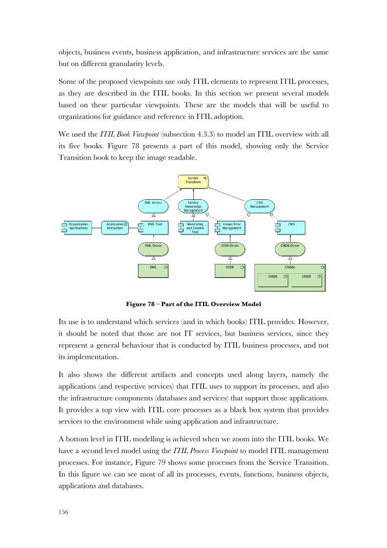
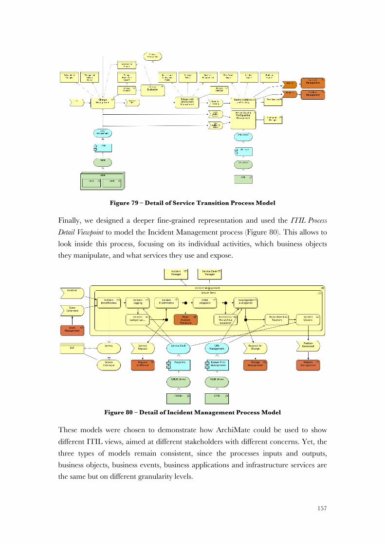
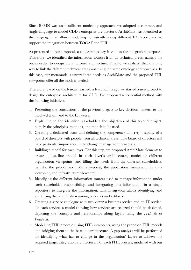
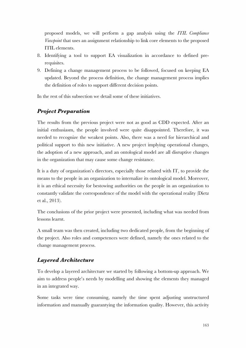
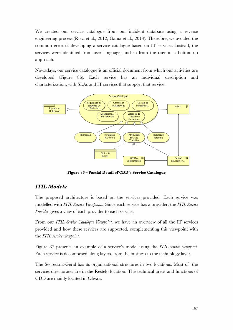
5.1! ITIL Models ................................................................................................. 155!5.2! Field Study ................................................................................................... 158!
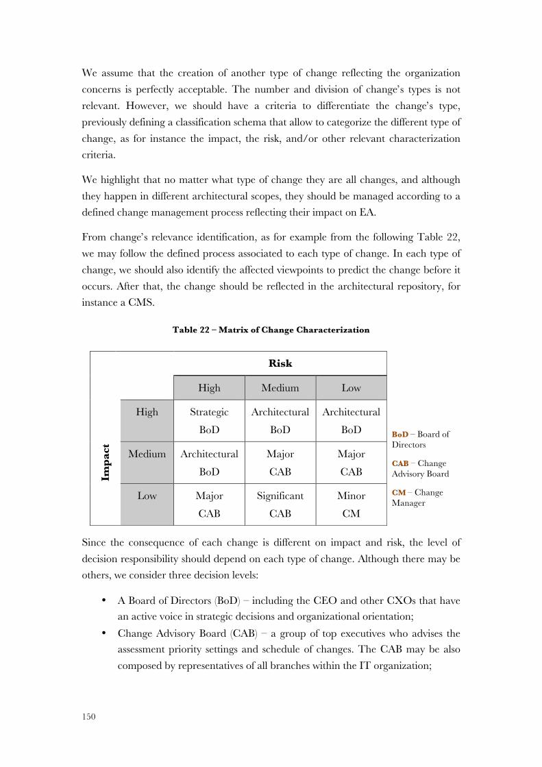
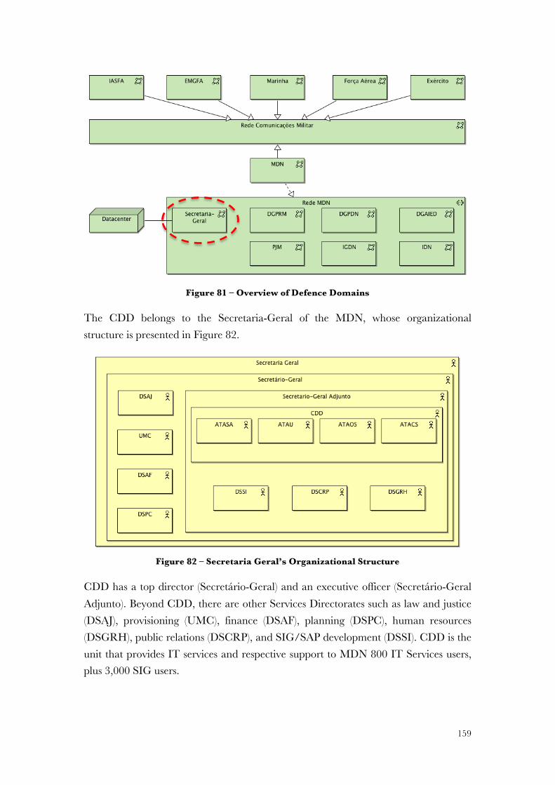
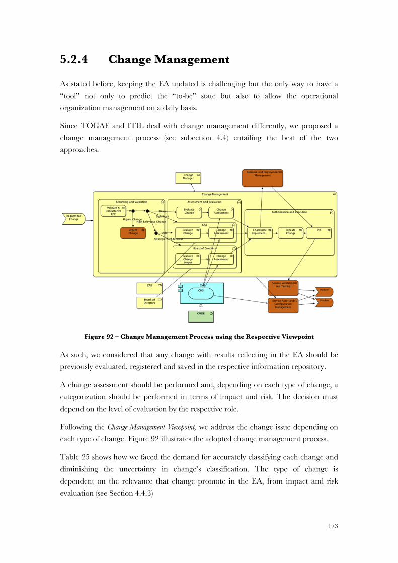
5.2.1! Organization ............................................................................................ 158!5.2.2! Historical Overview ................................................................................. 160!5.2.3! Current EA Project .................................................................................. 161!5.2.4! Change Management .............................................................................. 173!5.2.5! Summary ................................................................................................. 175!
6! EVALUATION ............................................................................. 177!6.1! Wand and Weber Method ........................................................................... 178!6.2! Moody and Shanks Framework ................................................................... 179!6.3! Action Design Research ............................................................................... 182!
6.3.1! Interviews ................................................................................................. 183!6.3.2! Field Study ............................................................................................... 185!
7.1! Answer to Research Questions ..................................................................... 189!7.2! Main Contributions ...................................................................................... 191!7.3! Limitations .................................................................................................... 192!7.4! Publications .................................................................................................. 193!7.5! Future Work ................................................................................................. 195!
REFERENCES .................................................................................. 197!APPENDIX A –! ARCHITECTURE MODELLING LANGUAGES .......................... A-1!
Business Process Modelling ................................................................................... A-1!IDEF ...................................................................................................................... A-3!
APPENDIX C –! EA DEFINITIONS AND CORE CONCEPTS ............................ C-1!APPENDIX D –! ARCHIMATE CONCEPTS AND DEFINITIONS ........................ D-1!APPENDIX E –! SOA ELEMENTS .......................................................... E-1!APPENDIX F –! ITIL ARTEFACTS AND PROCESSES .................................... F-1!APPENDIX G –!CONCEPT MAPPING BETWEEN ITIL AND ARCHIMATE ......... G-1!APPENDIX H –! IMAGES FROM THE FIELD STUDY .................................... H-1!
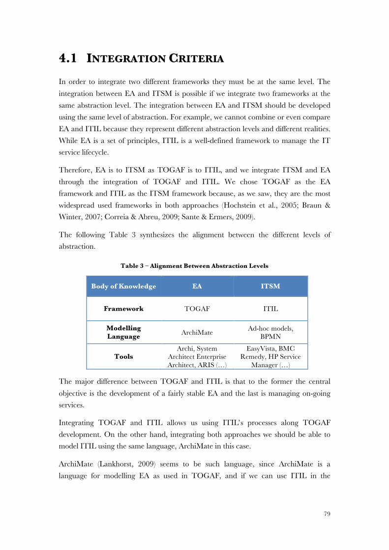
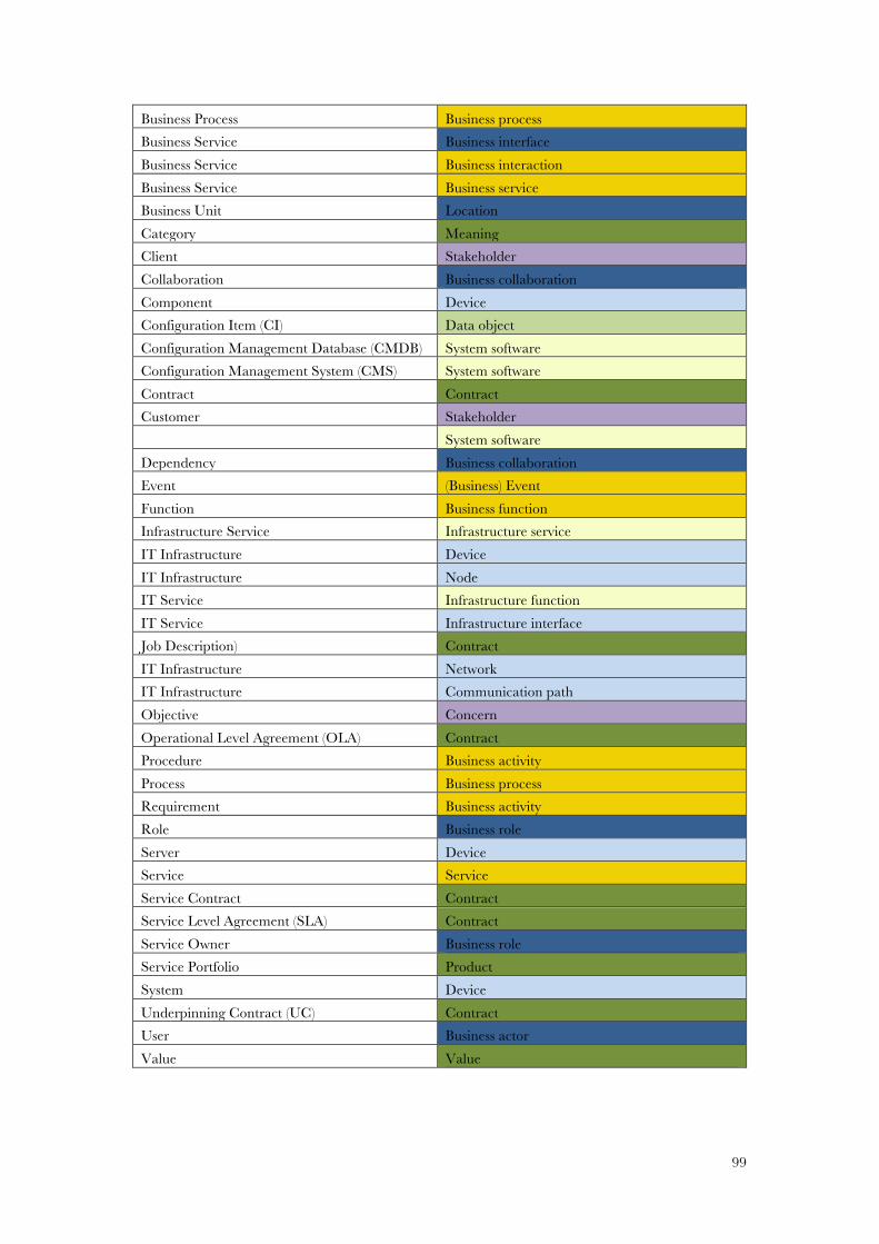
Table 27 – Concept's Mapping Between ITIL and ArchiMate ............................... G-1!
xxvii
ACRONYMS ADM – Architecture Development Method
BPMN – Business Process Modelling and Notation
CEO – Centro de Engenharia Organizacional
CI – Configuration Item
CIO – Chief Information Officer
CMDB – Configuration Management Database
CMMI4SVC – Capability Maturity Model Integration for Services
CMS – Configuration Management System
COBIT – Control Objectives for Information and related Technology
CRM – Client Relationship Management
DSR – Design Science Research
E2AF – Extended Enterprise Architecture Framework
EA – Enterprise Architecture
E2AF – Extended Enterprise Architecture Framework
EAM – Enterprise Architecture Management
EAP – Enterprise Architecture Planning
EO – Enterprise Ontology
ERP – Enterprise Resource Planning
FEAF – Federal Enterprise Architecture Framework
IAF – Integrated Architecture Framework
IDEF – Integration Definition
IEC – International Electrotechnical Commission
IEEE – Institute of Electrical and Electronic Engineers
IS – Information Systems
xxviii
ISA – Information System Architectures
ISO – International Organization for Standardization
RFC – Request For Change
IT – Information Technologies
ITIL – IT Infrastructure Library
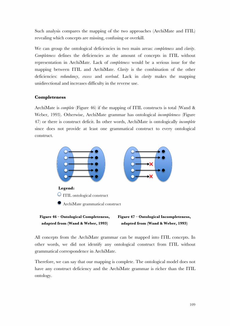
ITSM – IT Service Management
SLA – Service Level Agreement
SOA – Service Oriented Architecture
TEAF – Treasury Enterprise Architecture Framework
TOGAF – The Open Group Architecture Framework
UML – Unified Modelling Language
WFM – Workflow Management
1
1 INTRODUCTION We live in times of scarce resources. Rationalization is an imperative, even a survival condition for organizations. Convergence is a critical mote to follow standards with proved results, especially those based on best practices, minimizing the risk of experimental efforts and the costs. Moreover, cost reduction is an imperative, and overlapped projects should be avoided.
Information Technology (IT) plays a fundamental role in organizations. The growing demand on IT leads to the improvement of key concepts related to Enterprise Engineering, in particular the alignment between IT and strategic objectives and cost reduction initiatives (Weill & Ross, 2004; Tiwana & Konsynski, 2010). An integrated approach to business and IT is indispensable.
In fact, organizations and IT are architecturally so merged that it is hard to define where one ends and the other begins. The impact of IT in organizations is ever growing, leading to an also growing demand for IT management. The more important is the role of IT and the more complex is the IT infrastructure, the harder it is to manage. As IT infrastructures become more intricate, the cost to operate them rises. IT departments have to control this constantly growing complexity.
To satisfy the increasing demand of IT, organizations strive for effective and efficient IT management. Demands, opportunities, and threats are constantly changing. Therefore, organizations must adapt their structures in order to face emergent challenges. Both the need for a perfect alignment and the high inter-dependence between IT and the organizations’ structures increase the pressure to define IT structures that meet these demands (Zacarias et al., 2010).
Organizations relate different concepts such as people, relationship, structure, strategies, objectives, processes, and IT. The alignment between different organizations’ concepts, architectures and views is, more than ever, a requirement. Moreover, alignment issues are in the top of CIO priorities for the past two decades (C. Pereira & Sousa, 2005; Chen, 2008; Society for Information Management, 2010).
Enterprise Engineering considers the ongoing developments of social theories that describe the relations of people, technology and organization’s dimensions. Enterprise Engineering focus on continuous and mutual influential loops that originate emergent (some unexpected) behaviors and can only be understood through continuous appreciation and analysis (Martin, 1995).
2
Thereby, Enterprise Engineering involves the creative application of scientific principles to develop (including design and implementation) organizations; to operate the same with full cognizance of their design; and to forecast their behavior considering the environment (Greefhorst & Proper, 2011). Therefore, Enterprise Engineering studies an organization systemically as a system interacting with technology in different ways (Liles & Presley, 1996).
For many years now, different efforts were made related to Enterprise Engineering. However, results are far from expected, as proved by the disparate myriad of frameworks and different approaches that have been developed. The gap between the results obtained and expected are far from satisfactory, leading to an increasing interest in alignment efforts and related frameworks (Weiss & Anderson, 2004).
Today, there is no fully complete framework to be used as a comprehensive off-the-shelf Enterprise Engineering framework, ensuring the alignment between IT services and the organization’s concepts and artifacts. In fact, different frameworks are often used complementary and, most of the times, simultaneously. Beyond the difficulties associated with the governance of simultaneous initiatives, parallel projects imply a duplication of resources and costs. Indeed, even with shared infrastructures we could hardly avoid a duplication of data repositories, procedures and human resources, to maintain different efforts aligned.
From these initiatives, two main approaches have had outstanding relevance: Enterprise Architecture (EA) and IT Service Management (ITSM).
This dissertation will pay closer attention to EA and ITSM through their two best known and used frameworks, respectively The Open Group Architecture Framework - TOGAF (Open Group, 2011) and IT Infrastructure Library – ITIL (Cabinet Office, 2011a).
EA is a designation that summarizes the relevant concepts in an organization, how they are related, and how they fit and work together in different perspectives and with different views. In fact, EA defines a coherent whole of principles, methods and models that are used as an integrated approach in the design and realization of the enterprise’s organizational structure, business processes, information systems and infrastructure technology. As such, EA provides a common base for understanding and communicating how to structure systems to meet strategic objectives (Zachman, 1987; Spewak & Hill, 1992; Ross, Weill, & Robertson, 2006; Radhakrishnan, 2008).
3
An EA is a vital instrument for addressing organization-wide integration, allowing the integration of all organization concepts and granting the alignment between business and IT (Lankhorst & Drunen, 2007).
Different EA frameworks have been developed. From these, the aforementioned open standard TOGAF (Open Group, 2011) has gained major relevance (Sessions, 2007; Sante & Ermers, 2009) and this is why we focus our attention on this framework instead of any other.
ITSM is a reference model with an integrated approach to effectively and efficiently manage systems’ complexity in order to deliver IT services. IT services provide a foremost IT alignment to organizations’ needs with guaranteed quality (Brenner, 2006; Gama, Silva, & Mira da Silva, 2011), and cost and risk reduction (Hochstein, Zarnekow, & Brenner, 2005).
In this context, a reference model is an abstract framework representing the relationship of a set of defined concepts recognized in a specific domain enabling communication among stakeholders of the same interests (OASIS, 2006)
Although there are many frameworks for ITSM, ITIL is the de facto standard for implementing ITSM (Hochstein et al., 2005). ITIL is a process-focused approach to the identification, planning, delivery and support of IT services to the business through a service lifecycle (Bon et al., 2007).
Since ITIL is the most well-known and most widely used framework in ITSM, also used in daily operation in thousands of organizations worldwide (Hochstein et al., 2005; Kashanchi & Toland, 2006; Braun & Winter, 2007; Johnson et al., 2007; Sharifi et al., 2008; Ayat et al., 2009; Correia & Abreu, 2009; Lahtela, Jantti, & Kaukola, 2010; Peyret, 2011b), we focused our research on this approach.
1.1 MOTIVATION Even though ITSM and EA are both managerial approaches, they have different focus: ITSM primarily focus on IT service management (Baioco et al., 2009) while EA are related to alignment, organization representation, and IT Governance as the basis for Enterprise Engineering initiatives (Ross et al., 2006).
However, since both frameworks have begun addressing the issue of business/IT alignment, they are increasingly overlapping. At the same time, the relevance of IT has changed in organizations. IT is not anymore a mere support for business
4
operations instead, the increase importance of IT lead in define how business people should undertake their work (Venkatraman, 1994; Bharadwaj, 2000).
Nevertheless, a survey from Forrester (Peyret, 2011b) found that more than 50 percent of EA groups are not involved in ITIL adoption as recently as 2010. Another higher percentages is only minimally involved. According to Forrester, the reason is because only in version 3 of ITIL the role of enterprise architect has been identified although limited to a single domain: service design. Among the other ITIL process domains, design and strategy are implemented less frequently. Furthermore, Forrester has also found that the drivers for ITIL adoption do not include EA (Peyret, 2011b).
We conducted a research overview in this area and it has been surprisingly hard to find empirical or peer-reviewed work relating the two most prominent approaches in the Enterprise Engineering field, EA and ITSM. Besides both approaches are complementary, as far as we know, no integration proposal fully accepted has been developed.
Academic journals generally focus on the interesting problems of new systems development and emerging technology, rather than the mundane issues of integration (Betz, 2003).
Although some have tried to integrate these two approaches by identifying several benefits from the relationship and integration of ITSM and EA, (Braun & Winter, 2007; Thorn, 2007; Correia & Abreu, 2009; Nabiollahi, Alias, & Sahibuddin, 2010) we did not identify any satisfactory results, as presented in section Literature Review.
This dissertation covers these two widely used frameworks, and proposes guidelines to adopt a single initiative that involves the integration between EA (TOGAF) and ITSM (ITIL). A single initiative integrating EA and ITSM would avoid duplicated efforts and resources increasing synergies through a common and preferable core.
In this dissertation, we present a proposal to integrate EA and ITSM through the integration of TOGAF and ITIL frameworks using the best of these two mature and proved frameworks, giving a scientific contribution to this area with some published papers.
1.2 PROBLEM AREA Organizational efficiency and effectiveness results from the alignment between organizational needs and dimensions (Ostroff & Schmitt, 1993). An organization has different dimensions, which correspond to different views and viewpoints, namely
5
related with people, organizational perspectives, and technological infrastructure. That’s why organizations are struggling to adopt practices that allow the best results to achieve alignment between IT and organization’s dimensions.
EA and ITSM are approaches of Enterprise Engineering focusing on the alignment between IT and organizations’ dimensions. TOGAF is the most used EA framework and ITIL is the dominant framework for ITSM.
The problem area is where the phenomena of interest resides (Hevner et al., 2004). The problem area of this research is Enterprise Engineering, due to the environmental dimensions with a focus on the alignment of the organization’s dimensions.
This research is thus a contribution to Enterprise Engineering providing a proposal to integrate EA and ITSM initiatives through the integration of TOGAF and ITIL.
The goal of this research is to acquire knowledge that enables the development and implementation of a solution to an unsolved and fundamental problem faced by many organizations.
1.3 PROBLEM The early IT departments were organized in silos usually operating in a standalone mode and barely connected to the business. At that time, “quality” was the main focus and any improvements were based on methods. Standards for Service Management and Enterprise Architecture initiatives were born in that era (IBM Corporation, 1981).
The trend towards organizing work based on best practice models is a result of a growing complexity from the relationship between IT and business (Sante & Ermers, 2009). From an internal optimization, the organizations’ next efforts were in customer satisfaction through service delivery. For the first time, the potential of IT supporting business was recognized. IT became increasing the value added in service delivery through a well-defined value-chains of processes, from IT to business and vice-versa.
However, the alignment between business and IT requires an integrated approach to all concepts and artifacts of the organization (Nadler, Gerstein, & Shaw, 1992). Different initiatives have been developed in order provide the alignment between business and IT. From those, as aforementioned, two distinct frameworks have gained enhancement: TOGAF and ITIL representative of the two most distinct approaches, respectively, EA and ITSM.
6
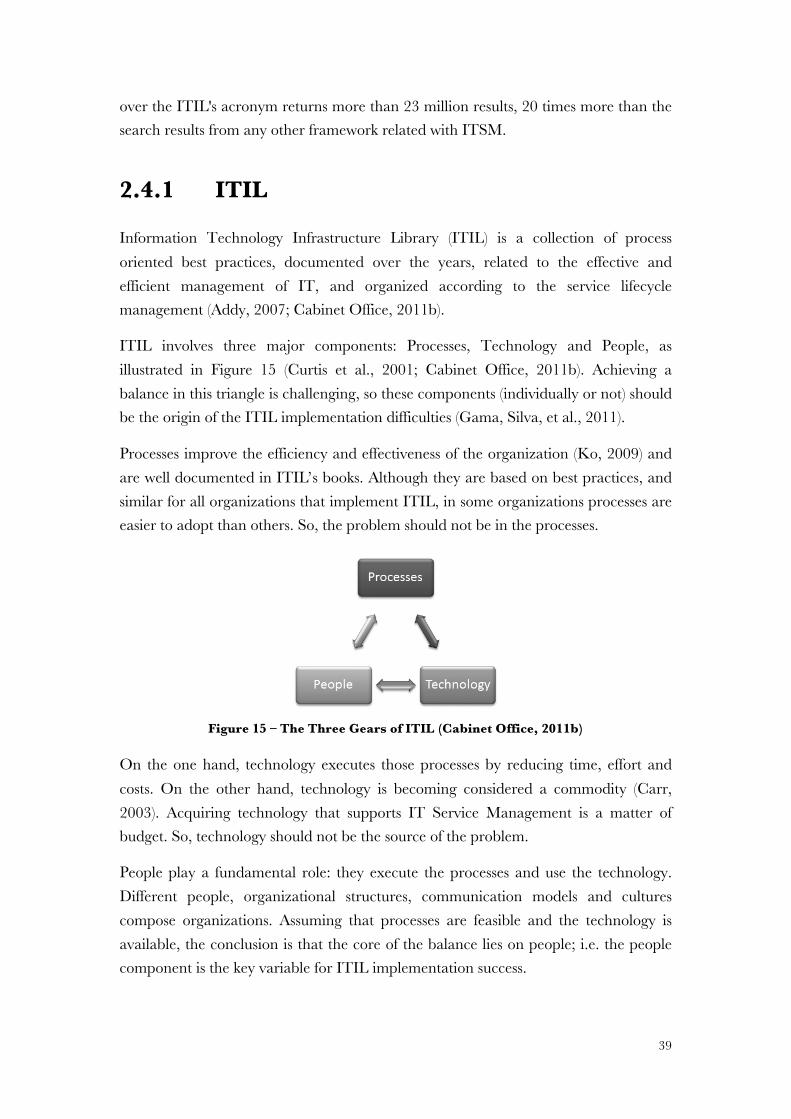
On the one hand, studying ITIL involves three major components: Processes, Technology and People (Curtis, Hefley, & Miller, 2001; Cabinet Office, 2011b). On the other hand, EA is an organization model that specifies its decomposition into functional parts, defines those parts, as well as the orchestration among them, to manage and align IT assets, people, operations and projects to support business objectives and strategies (Ross et al., 2006; Lankhorst, 2009).
Both TOGAF and ITIL are business oriented, aiming to ensure the consistency in the development of new products and services addressing business requirements. However, once TOGAF and ITIL are not connected their respective teams work separately with little opportunity to share expertise. On the other hand, these two approaches developed in parallel imply a duplication of efforts and resources, loosing synergies and increasing costs.
The efforts spent in managing organizational data and resources from these two different initiatives might become unmanageable, which will influence the effectiveness and benefits of both implementations.
As both frameworks have a lot in common, they should be integrated to avoid duplication or overlapping. What is often seen between TOGAF and ITIL is that they usually describe the same topics from different angles, and in some cases those descriptions seem to conflict (Cabinet Office, 2011a; Open Group, 2011).
Despite the experts’ recommendation to the integration between TOGAF and ITIL, a commonly accepted integration proposal has not yet been made (Peyret, 2011b).
Pragmatism should be a guiding principle implementing a framework. Such purpose implies a cohesive approach, integrating the unique characteristics of each one framework and leveraging what is common. Architects and service managers should join efforts to align business and IT with mutual understanding. Specialists from both domains should work together to achieve a solution that has not yet been identified, both in the framework description neither in related work.
1.3.1 Thesis Statement
Formally, a problem can be defined as the difference between an expected state and the current state (Hevner et al., 2004).
Since TOGAF and ITIL are developed with different focus but covering areas of common interest, we propose to integrate both initiatives into a unique framework,
7
sharing the same team and resources, increasing synergy and solving a problem that can be defined as:
The absence of integration between Enterprise Architecture and IT Service Management leads to misalignments and promotes a waste of resources.
1.3.2 Research Objectives
Through this research, we will provide the guidelines to adopt a single initiative that involves, more than the merger and alignment, the integration between TOGAF and ITIL approaches. Thus, this research provides a proposal to adopt a common guidance of integration between TOGAF and ITIL.
The research objectives should ensure that:
It is possible to integrate Enterprise Architecture and IT Service Management through TOGAF and ITIL integration; there is a path that ensures the integration; once achieved, the integration can be kept updated.
1.3.3 Research Questions
TOGAF’s EA principles are a coherent way to represent an organization as a system, relating multiple dimensions. The widespread scope of ITIL involves all organizational dimensions.
Both approaches should be integrated, sharing resources to a common understanding of organizational representation, along all dimensions and views.
Therefore, this research, “Integrating Enterprise Architecture and IT Service Management” through TOGAF and ITIL Integration, will be answered through the following research questions that subdivide the problem:
Q1: Does it make sense to integrate the two approaches?
Q2: How to integrate both approaches, which is the key path to integration, and how can the integration be defined?
Q3: How to represent the integration between the two approaches and, especially, their relationship?
8
Q4: Considering the effort and magnitude needed to build and maintain coherent information, how to keep the integrated information up-to-date and operationally usable on a daily basis?
The answer to these questions derives more from the process side of the solution than any other one, namely technological. The solution to the problem we try to address should encompass a conceptual model, independent of tools or adopted frameworks.
1.4 RESEARCH METHODOLOGY Considering TOGAF and ITIL together is a problem from Enterprise Engineering area. The interaction of people, organizations’ dimensions, and technology needs to be qualitatively assessed to allow the understanding of the developed theory or problem solving (Hevner et al., 2004).
We should develop and validate a proposal to solve our problem, but we had no initial validated theory and the existing knowledge was insufficient (Hevner et al., 2004; Oates, 2006; Baskerville, 2008). Therefore, the methodology chosen was Design Science Research (DSR) as the methodology that best enables research in Enterprise Engineering.
We selected this methodology because it is focused on problem solving by creating and positioning an artifact in a natural setting. DSR seeks to create innovative ideas, addressing research through the development and evaluation of designed solutions in order to meet identified needs over interactive steps, enabling us to understand the nature of the causes and design solutions. DSR is the best research methodology to create and evaluate a solution to solve the identified problem (Hevner et al., 2004; Oates, 2006).
This methodology also attempts to create solutions that serve human purposes, rather than natural science that tries to understand reality. DSR provides a solution but also studies the artifacts as they adapt to their changing environment and to changes in their underlying components (March & Smith, 1995).
Our research objectives are therefore qualitative and analytical. The research produces findings without quantification due to the absence of statistical or numeric values (Strauss & Corbin, 1990).
Qualitative research is more useful to our problem since the collection of information is made through perception and business case evaluation (Hines, 2000; Skinner, Tagg, & Holloway, 2000). Qualitative research was developed through processes with
9
interactive steps as DSR follows a process model with sequence activities (March & Smith, 1995; Peffers et al., 2007). DSR enables us to understand the nature of causes and design solutions getting products as outputs (Aken, 2005; Oates, 2006).
Analytical research was conducted by factual analysis and the evaluation of different perspectives relating IT Service Management (ITIL) and Enterprise Architecture (TOGAF).
DSR products are of four types that are innovative and valuable (March & Smith, 1995; Hevner et al., 2004): constructs, models, methods, and instantiations. Constructs are the “language” to specify problems and solutions (e.g., modelling primitives implemented by metamodels of modelling tools). Models use this language to represent problems and solutions (e.g., process models implemented as workflows). Methods describe processes, which provide guidance on how to solve problems (e.g., project methods implemented during software package introduction). Instantiations are problem-specific implementations that aggregate constructs, models, and methods.
In this dissertation we will propose: the EA principles and the concepts from TOGAF and ITIL as Constructs; a Method to TOGAF and ITIL concepts’ integration; as Models an ITIL Metamodel and EA viewpoints from ITIL perspective; Implementations with a real-world case and through the modelling of all ITIL processes and functions.
1.4.1 Design Science Research Methodology
The DSR methodology aims at the development of solutions to identified problems and it is applied according to two main processes as illustrated in Figure 1 (March & Smith, 1995): build and evaluate.
Building is where we construct the solution for a specific purpose. Evaluation is the process of determining how well the solution performs (March & Smith, 1995).
We follow Peffers (Peffers et al., 2007) in which both build and evaluate processes are composed by three stages each.
In stage 1 we define our research problem and justify the value of a solution, defining the objectives for a solution in stage 2. At the end of the build process we will have the construct with the domain definition and the definition of concepts, principles, methods, and models. This stage occurs after a literature review and requires a construction methodology.
10
Figure 1 – DSR, adapted from (March & Smith, 1995; Peffers et al., 2007)
In this context, we understand a methodology as a collection of procedures to help the development of a new or innovative idea, as is the DSR methodology. So, at the end of stage 3 we conceptualize a construct describing the problem, specifying the solution and modelling the relation among concepts (Hevner et al., 2004; Winter, 2008).
As we will see later in this dissertation, the ITIL metamodel is the basis for representing ITIL integrated with TOGAF. This research shows the relevance of a specification of ITIL concepts and the importance of their representation and integration in TOGAF.
In addition to the build process, the DSR methodology has an evaluation process where the solution is demonstrated and evaluated. This is very similar to Action Research (Sein et al., 2011). However, Action Research is focused on problem solving through social and organizational change and DSR is focused on problem solving by creating and positioning an artifact in a natural setting. On the other hand, Action Research is clearly focused on discovery-through-action whereas DSR is focused on discovery-through-design (Iivari & Venable, 2009).
The utility, quality and efficiency of the build process must be rigorously demonstrated through well-performed evaluation methods. In stage 4, we use our proposal in a field study within an organizational context to solve a research problem. In particular, we demonstrate our proposal with a field study in Centro de Dados from the Defence Ministry. After that, we did the evaluation, in stage 5, using some of the methods proposed in DSR.
Infe
renc
e
Theo
ry
How
to K
nowl
edge
Met
rics,
Analy
sis K
nowl
edge
Disc
iplin
ary K
nowl
edge
Identify problem & motivate
The absense of integration
between EA and ITSM
Define objectives of a
solution
A single initiative merging TOGAF
and ITIL approaches
Design & development
Define principles, concepts,
methods and models
Demonstration
Use the proposal in an
organisational context to solve
an identified problem
Evaluation
Practitioners interviews;Wand and
Weber ontological
analysis;Moody and
Shanks framework
Communication
This thesis;Papers
published in journals and international conferences
Integrate TOGAF and ITIL
approaches
Build Evaluate
Define requisites; A key path to
integrate
ITIL metamodel;ArchiMate
specializationCase study
2 31 4 5 6
11
In the end, the undertaken research must be presented to expert audiences to validate the proposal. We published papers to present our contribution to the scientific research community, thus fulfilling stage 6.
Ontology Engineering Process
Although the DSR methodology is widely mentioned, apart from some orientations, the methodology guidelines are not clear or rarely applied (Hevner et al., 2004). The methodological guidelines’ lack of specificity or inadequacy indicates its high level of abstraction (Peffers et al., 2007; Alturki, Gable, & Bandara, 2011).
Therefore, we used an ontology engineering methodology in the build process (Ostrowski, 2011) to identify and define ITIL’s concepts and respective relationship, creating ontological constructs. These findings are fundamental to the proposal as we see further.
The ontology engineering process, as illustrated in Figure 2, is used with the collaboration of practitioners from the same field apart from the more traditional literature review (Ostrowski, Helfert, & Xie, 2012). Applying this technique allows us to systematize a clear methodology, with defined steps and procedures, clarifying knowledge before developing a solution to the research problem.
Figure 2 – Simplified Ontology Engineering (Ostrowski et al., 2012)
Ontology engineering methodology is very similar to the SABiO (Systematic Approach for Building Ontologies) method proposed by (Falbo, 2004). SABiO encompasses the following activities: (i) purpose identification and requirement specification; (ii) capture existing relevant concepts as well as its relations, properties and constraints; (iii) explicitly represent the captured conceptualization; (iv) integration with existing ontologies for reuse and integration purposes; (v) ontology evaluation, to verify the truthfulness with the ontology purpose and requirements; and finally (vi) ontology documentation.
Following the ontology engineering process and reflecting on the structure of concepts, we started by defining the domain and the terms that constitute the first step defining the terms, their properties and purposes. From the identified terms and properties we acknowledge their limitations and evaluated possible constraints.
Define properties
Enumerate terms
Create concepts
Define relations
12
After we identified the terms and defined their properties, we created (construct) concepts and their relationships, providing the ontological vocabulary and symbols used to define a domain’s problems and solutions (Hevner et al., 2004; Vaishnavi & Kuechler, 2007).
The DSR methodology and the ontology engineering process promote a solution to an effective problem through the development of constructs, models, methods, and instantiations, taking together utility and theory.
Following DSR, in this dissertation we designed and developed a solution to an identified problem (see Section 1.3 Problem). Our research main goal was the integration between EA and ITSM through the integration between TOGAF and ITIL. We defined the constructs from the EA principles and a method to integrate the TOGAF and ITIL concepts. The achieved models and viewpoints, and the respective implementation in a field study, validate our proposal.
1.5 DOCUMENT STRUCTURE Besides the Introduction in this first section, we organized the dissertation following the DSR methodology, ending with References and Appendixes.
We divided the document in the following sections, illustrated with Figure 3:
• Section 1 presents the motivation, identifies the problem and the research objectives. It also formulates the research questions, the hypotheses and expected contributions from this dissertation, concluding with research methodology and document structure.
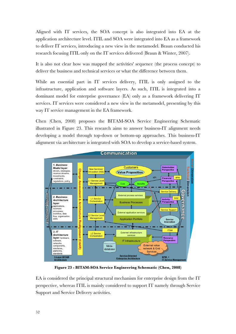
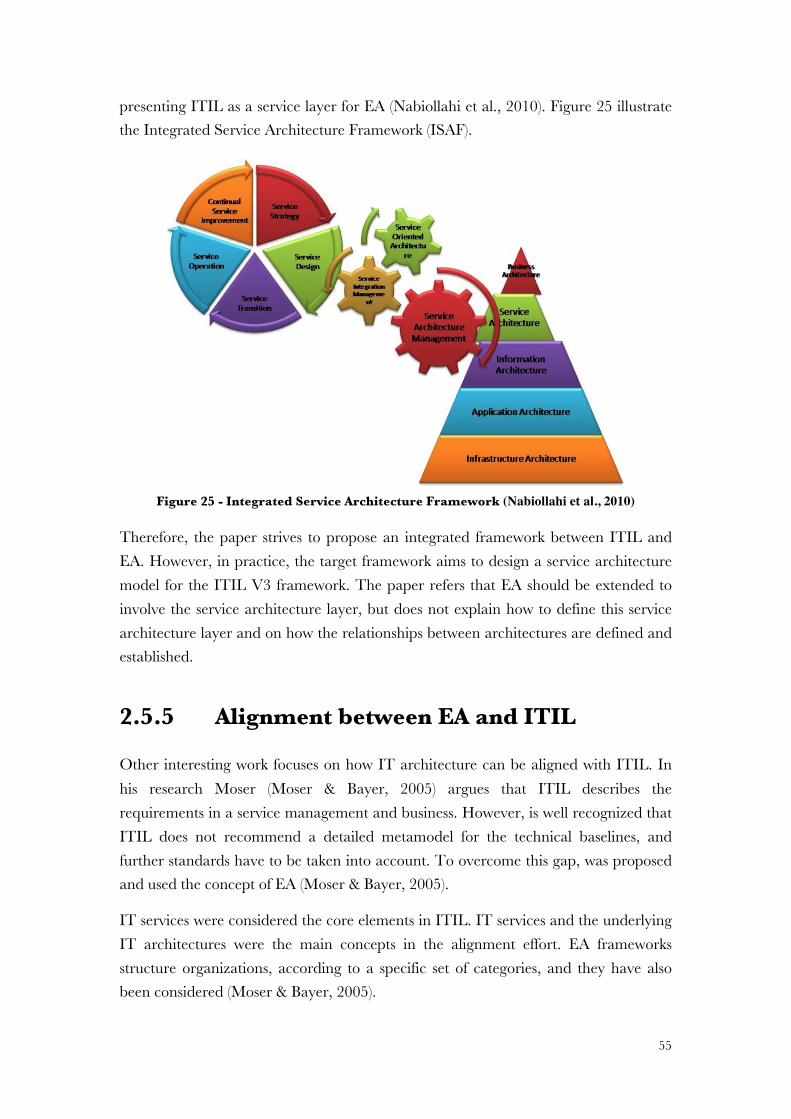
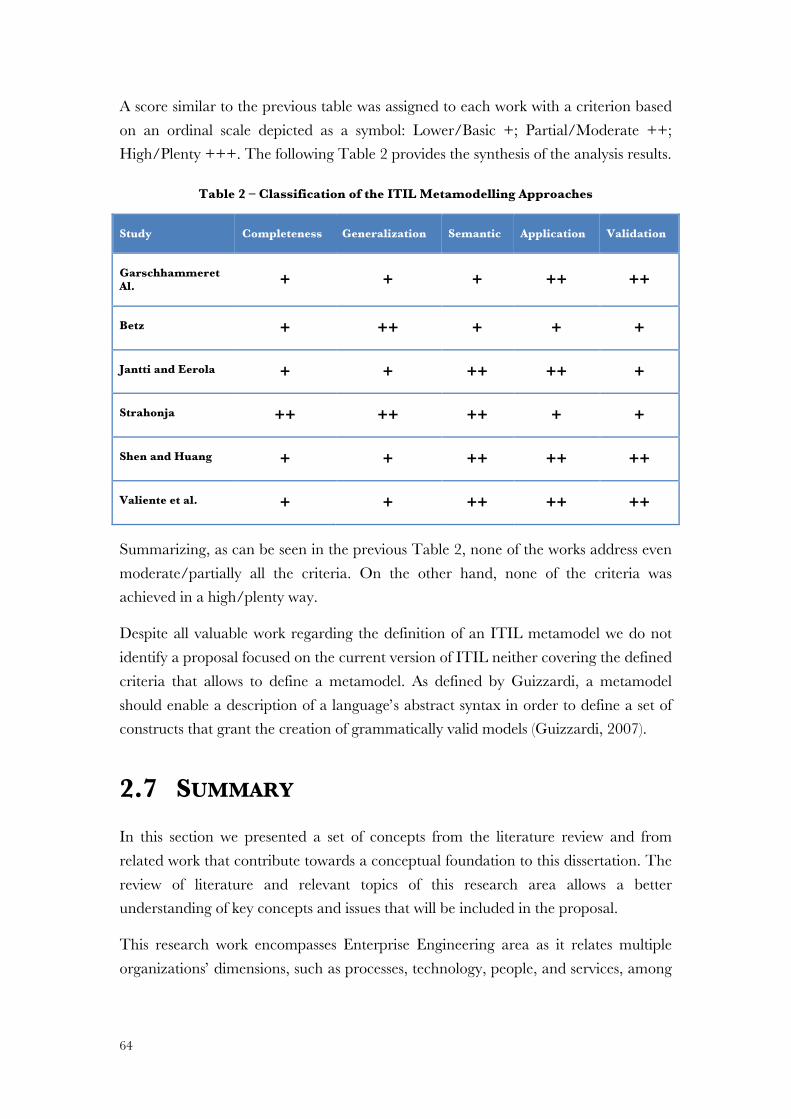
• Section 2 identifies the focus area of research and defines the scope. It also acknowledges the problem, from different perspectives, providing a review of related work in areas of knowledge interconnected with the dissertation’s problem. These areas are: Enterprise Architecture focusing on TOGAF; the adopted modelling language ArchiMate; Service Oriented Architecture; and IT Service Management with a focus on ITIL. After that, we develop an overview over the related work integrating TOGAF and ITIL. Afterwards we analyse some approaches related with the definition of an ITIL metamodel. We end this section summarizing the theoretical background and the topics to be addressed.
• Section 3 compares TOGAF and ITIL along the five ITIL’ books and conclude identifying the differences and the similarities between approaches.
13
Figure 3 – Document Structure
• Section 4 defines the objectives of the solution by presenting the theoretical foundations and the design of the “Proposal” to answer the research questions and to provide the expected contributions. This section defines the integration criteria between TOGAF and ITIL, verifies the integration and defines the integration method. After that, we present the change management as the process that ensures the update of the proposal. We conclude this section with a summary highlighting the principal conclusions.
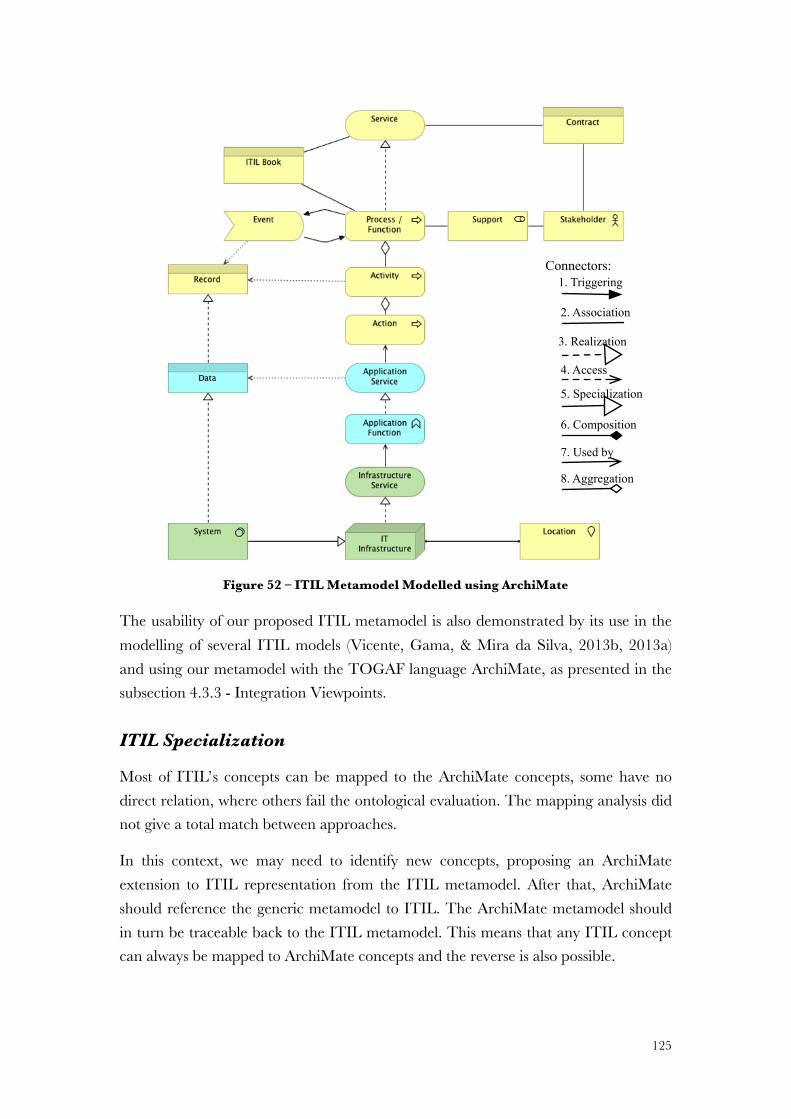
• Section 5, “Demonstration”, shows how the proposal can solve one or more instances of the problem. We present the ITIL modelling using the proposal on a field study with the implementation of the proposal.
Build
3. Proposal
2. Literature Review
2.1 EA 2.2 Modelling Languages 2.3 SOA
4. Proposal4.1 Integration
Criteria4.3 Integration
Model4.4 Change
Management
Evaluate5. Demonstration
5.1 ITIL Models 5.2 Field Study
6. Evaluation
6.1 Wand & Weber6.2 Moody &
Shanks
7. Conclusion7.2 Main
Contributions 7.5 Future Work
6.3 Action Design Research
4.2 Integration Verification
7.3 Limitations 7.4 Publications7.1 Answer to
Research Questions
1. Introduction
1.1 Motivation 1.2 Problem Area
1.3 Problem
Thesis Statement
Research Objectives
Research Questions
1. Introduction
1.4 Research Methodology
1.5 Document Structure
2.4 ITSM 2.5 Related Work 2.7 Summary
6.4 Summary
2.6 ITIL metamodels
4.5 Summary
3. Comparing TOGAF and ITIL 3.1 Service
Strategy3.3 Service Transition
3.4 Service Operation
3.2 Service Design
3.5 Continual Service
Improvment
3.6 Continual Service
Improvement
14
• Section 6 provides the “Evaluation” of our proposal and compares the results with the research questions. We followed different evaluation methods; including the Wand and Weber method, the Moody and Shanks framework, and Action Design Research with interviews in the field study.
• Section 7 “Conclusion” summarizes and evaluates this dissertation, the research questions as well as proposes themes for further work. Also includes the “Communication” in which we present the published papers.
15
2 LITERATURE REVIEW There are some questions that a literature review should answer (Gill & Johnson, 1991):
• What are the fundamental subjects and concepts related to our research? • What part of our research work has ever been investigated before and what
has not? • How does our research work relate to that done by others? • How have others defined and related the key concepts of our research? • What data sources have been used in developing a concept in the dissertation?
Based on the above issues, this section supports the proposal and assigns the foundation to answer our research questions. We reviewed the literature covering areas related to our problem, providing the fundamental background. We also developed an overview and evaluation of Related Work, identifying gaps and shortcomings.
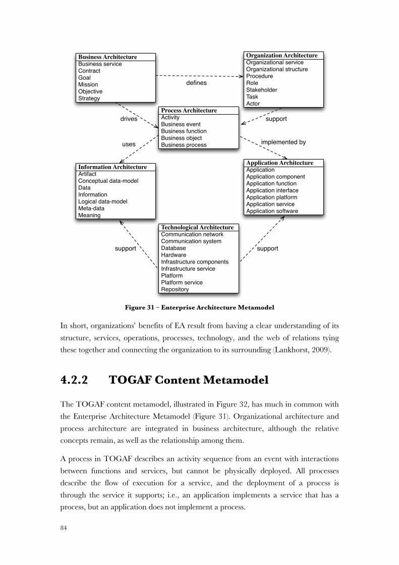
Our “Literature Review” analysis identifies the fundamental concepts covered by the dissertation. It is a long section because our dissertation covers and integrates different areas of knowledge. We start by review the problem area with “Enterprise Architecture” (EA) section as the main concept followed by the proposal. EA is presented as a set of principles, drivers, and concerns to be followed.
In the section “Modelling Languages" we review the architecture modelling languages with a critical analysis. We identify ArchiMate as the language to modelling an EA whose requirements best answer to our needs.
The “Service Oriented Architecture (SOA)” section reviews the SOA paradigm identifying services as an approach that distinct frameworks such as TOGAF and ITIL follow principles.
In the following subsections of this section we review IT Service Management focusing on ITIL as the best framework to ITSM (Hochstein et al., 2005; Braun & Winter, 2007; Correia & Abreu, 2009).
We also analyse the “Related Work” from disparate authors and different approaches, highlighting the most relevant topics to be considered in our proposal. After that, we analyse some research works related with ITIL Metamodels
We conclude this section with a summary of the Literature Review.
16
2.1 ENTERPRISE ARCHITECTURE Enterprise Engineering can be defined as the body of knowledge, principles, and practices related with the analysis, design, implementation and operation of an organization as a complex system of processes, systems and people (Liles & Presley, 1996; Dietz et al., 2013).
Enterprise Engineering recognizes Enterprise Architecture (EA) as the core representational element for the organization’s systems properties in different views and for many different purposes. We can state that EA has emerged as the basis of knowledge and representation in the organization itself, as a means of creating a coherent way of modelling an organization, assuming the methodology that best enables, efficient and effective, the planning and deployment of systems and IT aligned with business (Zachman, 1997; Open Group, 2011; Dietz et al., 2013).
In this context, an architecture is a fundamental layer and independent representation of a system, useful to represent different models as long as overall consistency is preserved by appropriately modelling the frameworks’ metamodel (Braun & Winter, 2005).
An architecture embodies artifacts, concepts, and components, their relationships with the environment and stakeholders.
Therefore, an EA is a symbolic representation of an organization in layers and artifacts that are relevant for an organization, such as structure, activities, processes, information, people, technology, goals and constraints, containing representations of individual facts, objects, and relationships that occur within the organization(Ross et al., 2006; Lankhorst, 2009).
However, even though EA principles make a clear reference to the relationship between dimensions and artifacts, they do not specify how to define and relate disparate concepts within an organization (Spewak & Hill, 1992).
Also, EA principles only provide an abstract view of organizations’ concepts omitting the fundamental foundation for an understandable knowledge (Dietz, 2006).
We define EA as a coherent whole of principles, methods, and models that are used as key elements in the design and construction of organizations’ structures, business processes, information systems, and technology infrastructures, in which:
17
• Principles involve the design and performance of different architectures, the specification of functional parts, their decomposition, as well as the orchestration among them;
• Models can be defined as the representation of organization’s architectures, artifacts and the relationship among them;
• Methods provide the steps for assisting in the acceptance, production, use, and maintenance of an EA.
Through this background, EA involves the design and realization of different dimensions which correspond to perspectives views (Correia & Abreu, 2009; Lankhorst, 2009).
A view is a plan describing the deployment of an architecture building block across the organization, giving a comprehensive view on how they interact, namely between business, application, information, and infrastructure architecture. A view pictures the architecture design in a matrix of organization dimensions (Rohloff, 2008).
Therefore,
A view can be described as the way each EA domain or stakeholder looks at different interests, its structure and elements from a specific perspective. As such, we will have a disparate variety of views in different architectures.
Different needs and scopes have suggested distinct frameworks and representations for modelling EA, having in common principles such as: holistic organization’s representation; relationships mapping between artifacts and concepts along architectures; independence and connection among layers (Hoogervorst, 2004).
Answering different needs, disparate authors have suggested distinct frameworks, for instance: Zachman Framework, IAF, E2AF, TOGAF, TEAF, CEO, FEAF, DoDAF, MODAF, and NAF, to name just a few. In Appendix B – we present an overview of some of the most relevant EA frameworks.
From all EA frameworks TOGAF has gained major relevance. Nowadays, TOGAF has a widespread acceptance and it is one of the leading architecture frameworks worldwide (Cameron & McMillan, 2013). For example, a simple Google search by TOGAF returns more results (more than three million) than all the others frameworks together. Therefore, we focus our research in the TOGAF framework (Sante & Ermers, 2009).
18
2.1.1 TOGAF
TOGAF (The Open Group Architecture Framework) is supported by The Open Group: a large community of practitioners, vendors and technology-neutral consortium, focused on a diverse range of open standards and affiliated certification programmes (Sante & Ermers, 2009; Open Group, 2011).
TOGAF is a framework providing a comprehensive approach to the design, planning, implementation and governance for EA. This framework provides an agreed baseline for strategic planning and tactical decision-making.
The first version of TOGAF (1995) was based on the US Department of Defence’s Technical Architecture Framework for Information Management (TAFIM). The following six versions of TOGAF addressed technology architecture based on the adoption of architecture in businesses at the time each was written. In 2002, the “Enterprise Edition” (version 8) was published, and was followed by a series of improvements expanding the scope of TOGAF from a purely technology architecture to an Enterprise Architecture, by including business and information systems architecture (Sante & Ermers, 2009).
The TOGAF’s evolution follows the changes in the architecture’s role within organizations. It has increasingly become a process to help organizations to make decisions about their future and to show them how to get there. By combining inputs from the whole organization and from different stakeholders, architects can help organizations to reduce the complexity of today’s IT and organizational landscape (Jonkers, Proper, & Turner, 2009) (Jonkers et al., 2009).
In fact, an architecture must be seen as an organization-wide process that will be directed by management, with the support of the enterprise architect. The (enterprise) architect has therefore changed from a technical individual to someone with organizational sensitivity (Sante & Ermers, 2009).
TOGAF’s latest version (version 9.1, published on 1 December 2011) expresses the need for closer alignment with the business, and the desire for simple implementation and greater usability (Sante & Ermers, 2009).
Alongside a higher level of detail in the description of the architecture, there is increasing reflection on the use of the architecture and its governance. This is the same kind of development evolution that occurred in IT Infrastructure Library (ITIL), where support to the business is now considered vital.
19
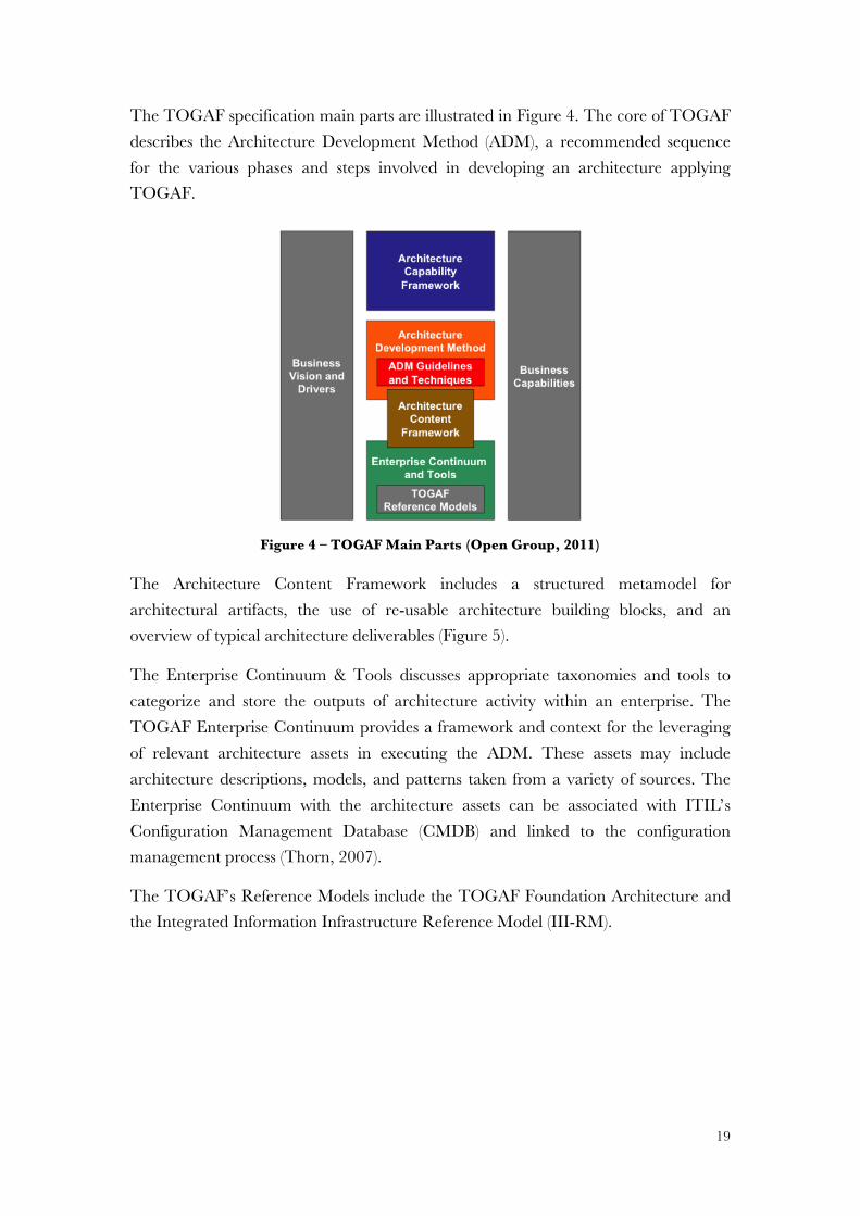
The TOGAF specification main parts are illustrated in Figure 4. The core of TOGAF describes the Architecture Development Method (ADM), a recommended sequence for the various phases and steps involved in developing an architecture applying TOGAF.
Figure 4 – TOGAF Main Parts (Open Group, 2011)
The Architecture Content Framework includes a structured metamodel for architectural artifacts, the use of re-usable architecture building blocks, and an overview of typical architecture deliverables (Figure 5).
The Enterprise Continuum & Tools discusses appropriate taxonomies and tools to categorize and store the outputs of architecture activity within an enterprise. The TOGAF Enterprise Continuum provides a framework and context for the leveraging of relevant architecture assets in executing the ADM. These assets may include architecture descriptions, models, and patterns taken from a variety of sources. The Enterprise Continuum with the architecture assets can be associated with ITIL’s Configuration Management Database (CMDB) and linked to the configuration management process (Thorn, 2007).
The TOGAF’s Reference Models include the TOGAF Foundation Architecture and the Integrated Information Infrastructure Reference Model (III-RM).
Finally, the Architecture Capability Framework, discusses the organization, processes, skills, roles, and responsibilities required to establish and operate an architecture function within an enterprise (Jonkers et al., 2009).
TOGAF ADM
The TOGAF ADM (Figure 6) provides a detailed and well-described iterative phasing framework for developing architectures to all EA’s domains.
The framework considers an overall EA as composed of a set of closely interrelated Architectures: Business, Information Systems (comprising Data and Application Architectures), and Technology (Lankhorst & Drunen, 2007).
TOGAF identifies a number of views, which are modelled in ADM (Lankhorst & Drunen, 2007). The TOGAF taxonomy of views is compliant with the IEEE 42010 (IEEE Computer Society, 2011).
21
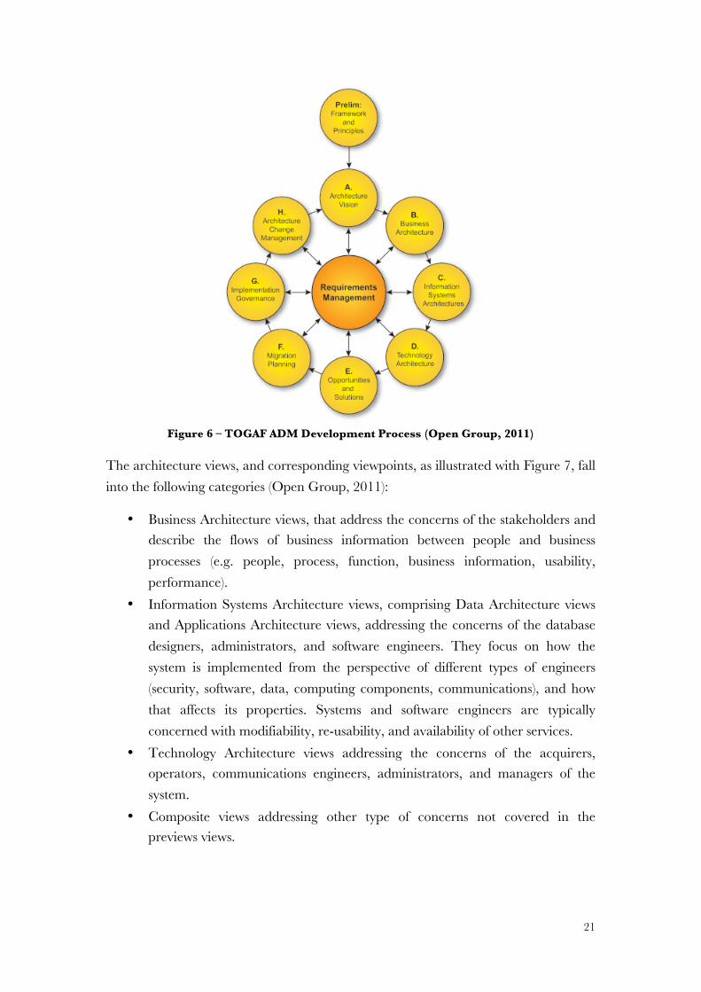
Figure 6 – TOGAF ADM Development Process (Open Group, 2011)
The architecture views, and corresponding viewpoints, as illustrated with Figure 7, fall into the following categories (Open Group, 2011):
• Business Architecture views, that address the concerns of the stakeholders and describe the flows of business information between people and business processes (e.g. people, process, function, business information, usability, performance).
• Information Systems Architecture views, comprising Data Architecture views and Applications Architecture views, addressing the concerns of the database designers, administrators, and software engineers. They focus on how the system is implemented from the perspective of different types of engineers (security, software, data, computing components, communications), and how that affects its properties. Systems and software engineers are typically concerned with modifiability, re-usability, and availability of other services.
• Technology Architecture views addressing the concerns of the acquirers, operators, communications engineers, administrators, and managers of the system.
• Composite views addressing other type of concerns not covered in the previews views.
www.via-nova-architectura.org March 2007 3
frameworks, guidelines, templates, a mapping of TOGAF to the Zachman framework,
etc.).
ADM
EnterpriseContinuum
ResourceBase
Figure 1. TOGAF [The Open Group, 2006].
TOGAF Architecture Development Method
Central to the discussion in this paper is TOGAF’s Architecture Development Method (ADM).
The framework considers an overall Enterprise Architecture as composed of a set of closely in-
terrelated Architectures: Business Architecture, Information Systems Architecture (comprising
Data Architecture and Application Architecture), and Technology (IT) Architecture. ADM is con-
sidered to be the core of TOGAF, and consists of a stepwise cyclic iterative approach for the
development of the overall enterprise architecture (Figure 2).
Figure 2. TOGAF ADM development process [The Open Group, 2006].
22
Figure 7 – Views in the TOGAF ADM (Open Group, 2011)
2.1.2 Critical Analysis
The ADM (Figure 6) is the core method of TOGAF (Open Group, 2011) describing the lifecycle of organization architecture through a cycle of phases for which we developed the following critical analysis.
Phase A: Architecture Vision
The Architecture Vision’s objectives are the development of a high-level vision of capabilities and the delivery of business value. Despite all concerns considered in architecture vision, in practice, when we develop an enterprise architecture it is not
www.via-nova-architectura.org March 2007 5
Figure 3. Views in the TOGAF ADM development process [The Open Group, 2006].
Enterprise Modelling
Modelling languages are an essential instrument for the description and communication of ar-chitectures, and languages and tools have evolved more or less “hand in hand”. In some cases methodologies and frameworks have grown around and are supplied together with architecture support tools, for instance in the case of UML and Rational, EPCs and ARIS [Scheer, 1994], and Testbed [Eertink et al., 1999]. In other cases, tool vendors have strived to endow their tools with new functionality in order to support frameworks or other modelling notations such as UML [Object Management Group, 2003] or the IDEF family [IDEF, 1993], besides their own proprietary notations (e.g., ARIS, System Architect). Languages and modelling notations are at the core of all these architecture support packages.
Most languages mentioned provide concepts to model specific domains, e.g., business proc-esses or software architectures, but rarely do they model the high-level relationships between these different domains. In current practice, architectural descriptions are made for the differ-ent domains. Although, to a certain extent, modelling support within each of these domains is available, well-described concepts to describe the relationships between the domains are al-most completely missing. Such concepts are essential to tackle the problems of business–IT alignment and architecture optimization in a systematic way.
23
clear how to put into action key elements such as vision, mission, business strategy and goals. Even when well documented, TOGAF does not give an answer to that need.
The architecture vision obliges us to clarify a strategy. However, this implies long time involving business people, which is difficult.
From the organization’s strategy and correspondent goals we have a starting point. However, we barely have this starting point, leading to a more often bottom-up EA modelling approach.
Although the creation of business scenarios is expected in this phase (Open Group, 2011), this may lead to misconceptions. Business analysts usually develop business scenarios with focus on time to market and with no other delivery concerns. For example, if we developed a product, which creates little profit, it is possible that the non-functional requirements are inadequately written or poorly implemented, or it is just an overall bad product. So we need to look at the value added in business architecture. Therefore, we always need to capture the value and how is delivered, which is often barely developed at business architecture. The value always depends on stakeholders’ needs.
Creating business scenarios in TOGAF is very similar to what we did with business services identification in our proposal, as we will see further on, in Section 4.
Phase B: Business Architecture
Business Architecture is a “prerequisite for architecture work in any other domain” (Open Group, 2011) documenting and describing the business, supporting functions, and respective relationships. A knowledge of the Business Architecture is fundamental for the next steps, namely for integration with strategy, financial management, objectives, KPIs, and other business’ aspects, specifically the business services. The architecture’s documentation defines the required business services to be aligned with the respective enterprise technology – the IT services.
We define IT service based on (Schekkerman, 2004; Vorisek & Jandos, 2010; Gama, Rosa, & Mira da Silva, 2013),
IT service is a coherent set of activities implemented by processes, delivered as expected by an IT service provider to an IT service consumer, usually a business service, which consumes or uses resources (such as applications, information, or people), supported by the infrastructure technology.
24
Each business service should be supported by the defined IT services and linked to an SLA between a service provider and the customer.
Despite its intrinsic value, Business Architecture is one of the weakest parts of the TOGAF framework. In fact, the Business Architecture is not very well described. Despite the reference to business model principles, goals, and drivers, it is not clear how to model it. First, TOGAF does not clarify the meaning of Business Architecture. Moreover, the Business Architecture is neither mentioned in Enterprise Continuum nor in Architecture Repository. It is merely referred as an EA requirement. Second, despite the several aspects enunciated in the Business Architecture phase, it still misses several important aspects such as processes and service delivery.
TOGAF seems too dedicated to identifying business capabilities through the development of the TOGAF’s Capability Assessment. However, this can be very difficult in a primary phase due to the lack of process representation and the inexistence of sufficient information to develop a coherent baseline related to business capabilities or even to the scope of the architecture.
Without a clear definition of business objectives, financial data, and business processes we cannot conduct a capability assessment against the current business processes. Moreover, it is difficult to internally conduct a capability assessment highlighting weaknesses in the current state.
From another perspective, this phase has a lot in common with the vision statement, also too descriptive at a high level, without effectively materializing a Business Architecture, namely in objectives’ definition. For instance, the definitions are missing and nothing is mentioned about standard best practices. Conversely, the Business Architecture phase mixes-up the approach to target architecture from top-down to bottom-up, which does not make sense considering the strategic objectives concern to the target architecture.
Another less effective area in the Business Architecture phase is the business modelling. The Activity Models are usually depicted using UML, without sufficient details and inputs for the following representations. Moreover, it is the only phase where we consider the business domain and we may lose some of the business specification representation – the business requirements. UML is good for software development but too complicated for business users, and to model a real business architecture expressing organization (Lankhorst, 2009).
In addition, in this phase there is the step “Identify Required Service Granularity Level, Boundaries, and Contracts” (Open Group, 2011). However, it is very difficult to
25
determine the granularity level at this stage because we can neither identify cross dependencies, neither needed boundaries. Business people barely understand architecture granularity. Granularity is something that we may have to decide later, after the Business Architecture definition, and after we shape the business services, business processes and the supporting architectures, more from the IT side. Granularity is easily identifiable from technical services.
We adopted Bohman et al. (Bohmann, Junginger, & Krcmar, 2003) where,
Technical services can be defined, as the decomposition of complex services into modular units of service simplifying its development and operation.
Nevertheless, this kind of granularity, at this stage, does not mean anything at all for the business. We believe that the TOGAF’s Business Architecture only makes sense from a software architecture background.
Finally, despite the importance of having a reference from which we develop the changing efforts, this phase does not give any definition, or real explanation, of what is a Business Architecture baseline. However, we should define a Business Architecture roadmap, thus avoiding starting without an effective planning, integrating the Business Architecture with the other architectures in a complete business roadmap.
Architecture Integration
Architecture integration relates different architectural domains through an integration framework. The more different the domains are, the more important is this framework to enable the architecture’s integration.
On the one hand, one of the TOGAF advantages is the existence of defined architectural domains (business, data, application, and technology). However, more and different domains imply different people working and with different detail levels. TOGAF does not clarify the detail level at vertical scope and usually it is not consistent. Nevertheless, the detail level should be the same along all the architectures. On the other hand, despite the compromise in developing different architectures, it is not clear how to integrate and relate architectures from different domains.
Tools and languages that enable the architecture integration assume a very important issue. We highlight the importance of a language allowing the integration between different architectures and the existence of the same detail level.
Finally, TOGAF covers different areas like SOA and security issues, but different areas are covered in different sections and it is not clear how the relation is established
26
among them. Furthermore, in TOGAF the SOA concept is too focused on technology and less on the overall concept of service.
Phase H: Change Management
The Change Management phase aims to establish and support the implemented organization architecture as a dynamic architecture; that is, one having the flexibility to evolve rapidly in response to changes in the technology and business environment (Open Group, 2011).
Although TOGAF defines a recommended sequence for the various phases in ADM, it does not define a scope. The scope should be determined by each organization, as a framework to pick and choose the parts that we think could help us. Each iteration will add resources to the organization’s Architecture Repository (Open Group, 2011).
However, the definition of objectives, organizational context and scope, at a preliminary phase of TOGAF, ignores the continual change of the organization environment. The identified architectures are too static and we need a framework reflecting changes in a smooth way. Otherwise, at each change, we have to start again and redo the same work.
Although Change Management is considered an essential part of the architecture’s permanent renewal (Open Group, 2011), it is not clear how TOGAF materializes change management. Since there are many valid approaches to change management, TOGAF allows the use of other change management processes in place, for instance ITIL (Open Group, 2011). The TOGAF's change management bridges the gap analysis between what is projected and achieved. This is quite different from change management in ITIL, where change management keeps updated the architectural information databases, as it should be kept in an enterprise architecture.
Management Framework
The TOGAF ADM is a generic method to be used by organizations in a wide variety of industry types and disparate geographies. It is also designed, if required, for use with a wide variety of other architecture frameworks (Open Group, 2011). However, despite TOGAF being presented as inclusive and incentivize the use of other architecture frameworks, such as ITIL, problems can occur.
TOGAF is a huge framework with many chapters and if we use another framework, with similar complexity, we may expect some overlapping of covered topics. On the one hand, this means some problems since people get used to one framework and it is
27
difficult to work in different frameworks. On the other hand, the development of an adopted framework usually signifies the use of related process and tools, and it is difficult to integrate different approaches. It is preferable to concentrate in only one framework, answering all the problems and needs.
Finally, TOGAF exhaustively defines the steps and expected deliverables but it is merely textually descriptive without a clear definition of processes. As such, TOGAF is a framework basically of “should have” items: TOGAF describes what should be done but not how to do it. In addition, TOGAF references are made to the multiple artifacts and diagrams without mentioning their creation and development practice.
Non-Architectural Inputs
Partnership and contract agreements are presented as non-architectural inputs to EA. However, partnership and contract agreements are usually done by a commercial part of the organization and might be difficult to get into the EA. Contract agreements should be included in EA. For instance, ITIL has processes to lead with suppliers, partnerships and contract agreements.
Another important limitation is that TOGAF viewpoints are confined to single architectural layers, making difficult the integration (or lack thereof) between the different architectural domains (Lankhorst, 2009).
Transition Phase
One of the biggest faults in TOGAF is the inexistence of a planned transition phase. Once planned and defined a preliminary phase, we need to test and deploy their deliverables through a planned transition phase. Without a transition phase, EA is usually very well delivered in paper, but lacking in execution. We should make sure that we really deploy the planned EA, because if we do not have our tools ready and tested through a service transition plan then problems can be expected.
TOGAF’s phases C to G
In section 3 (Comparing TOGAF and ITIL) we develop a critical overview of TOGAF’s other phases, highlighting the principal similarities and differences between the two approaches.
28
2.1.3 Summary
From TOGAF’s analysis we identified some limitations. It is not clear how some concepts are applied, namely those related with strategy identification, and especially with the Business Architecture.
Services identification is a lacking issue. Some efforts are placed in the identification of business capabilities too early in the phase of architecture development. The architecture’s granularly identification is also done too prematurely, leading to few results. Clearly, a transition phase, such as the Service Transition from ITIL, can mitigate some of these identified gaps.
The creation of a business service architecture could allow the establishment of business strategy and also its decomposition through architectural layers, connecting artifacts and elements.
The TOGAF ADM does not clarify how to integrate and relate architectures from other domains. Another limitation is that TOGAF viewpoints are confined to single architectural layers, making the integration with different architectural domains difficult.
On the one hand, integrating different approaches or frameworks in a single initiative allows the use of the same referential, namely the same modelling language. On the other hand, a single initiative would avoid the need of following different frameworks and cover different topics.
The change management process is mainly related to architectural changes, ignoring the continual change of organization environment. A change management process should cover any change, from the structural to the one on a daily basis.
TOGAF is too descriptive without consistent references on how to effectively develop an EA or on how to design viewpoints. A clear description on how to develop and achieve an architecture and respective processes is important.
2.2 MODELLING LANGUAGES Some approaches to enterprise modelling lack adequate semantic specification, leading to an inconsistent interpretation and use of knowledge underlying the terminology of enterprise models (Grüninger, Atefi, & Fox, 2000).
29
The absence of a strong and precise concept definition can lead the terms to become a source of confusion and lack of understanding. Especially in terms related to IT (such as application, information system, and business solution) tend to be used indistinctively in various scenarios (Pedro Sousa, Martins, & Sampaio, 2012).
Therefore, a modelling language should reflect a clear concept definition allowing their use in disparate contexts. An ontology is the basis for clear concept definition to a modelling language development, and metamodels are representations of ontological concepts’ relationships.
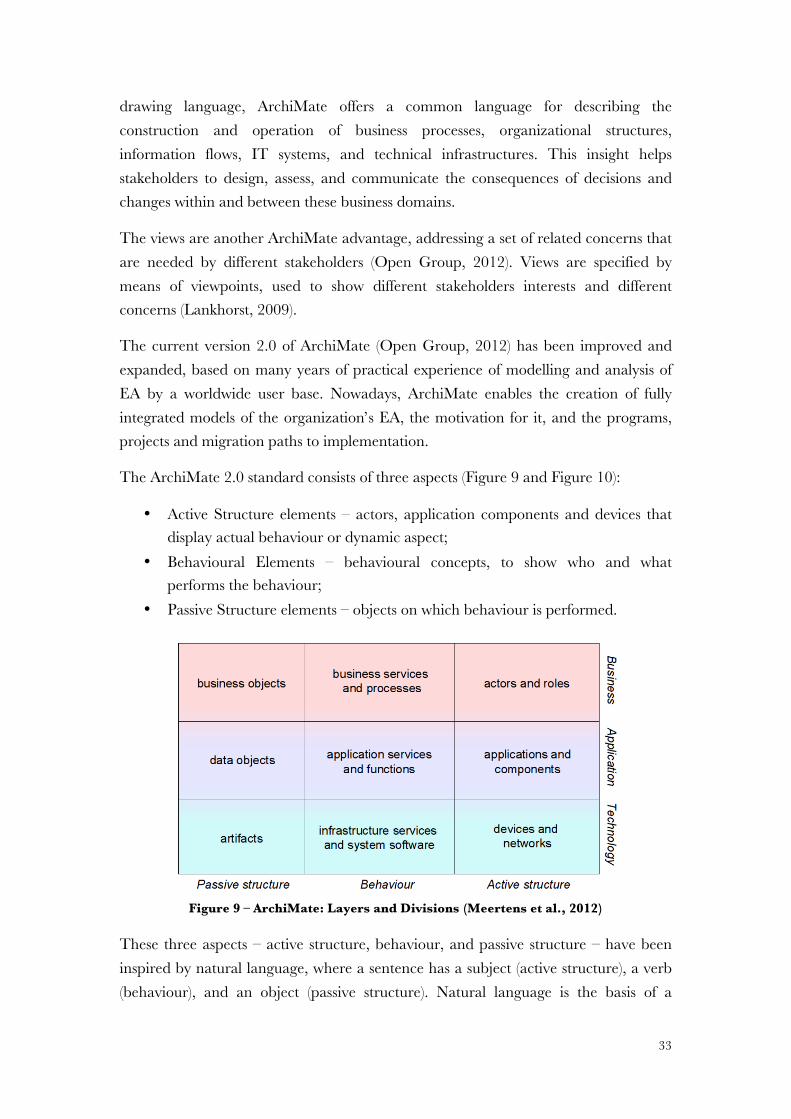
In the following sections we develop some considerations related with ontology definition and representation. After that, we present ArchiMate as the language to modelling EA.
2.2.1 Ontology’s Definition and Representation
One of the hardest tasks when developing projects within an organization, crossing different organizational functions and involving disparate people, is getting everyone to agree about the meaning of different concepts. Without an ontology agreement, different representations arise for the same reality.
However, the notion of concept is considered to be a subjective notion (Dietz, 2006). We based our definition of concept from Novak (Novak & Cañas, 2008) in which,
Concept is a perceived regularity (or pattern) in events or artifacts, representing knowledge.
Etymologically, the word ontology is composed by “onto”, meaning, “what exists”, and “logos” or “knowledge about”.
As mentioned by Dietz (Dietz, 2006), an ontology allows a formal and explicit specification of a shared conceptualization, providing a definition of the meaning of the existing concepts. An ontology is therefore a foundation for understandable knowledge, aligning individuals and organizations through a definition of concepts (Gruber, 1995; Dietz, 2006; Gama, Mira da Silva, & Francisco, 2011). An ontology can be defined as,
Ontology is a formal description of entities through the definition of properties, relationships, constraints, an behaviours. Thus, an ontology allow us to create a common understanding and shared knowledge in concept definition and classification.
30
A rigorous foundation for organizational design, analysis, and operation requires a formal semantic specification through the use of ontologies (Dietz, 2006). Once an ontology is an explicit conceptualization of what “exists” can be used to explicit a representation (Gruber, 1995).
An ontology can have an expressed representation by conceptual modeling grammars (constituted by vocabulary plus meaning) that allow us to construct representations of the real-world or from a particular domain (Shanks, Tansley, & Weber, 2003; Dietz, 2006).
In addition to the ontological concepts reference, it is preferable to have a graphical representation of the ontology in which the relationship is recognized among concepts. An explicit graphical representation as a model of concepts, especially their relationship, allows for (Zacarias, Pinto, & Tribolet, 2007; Gama, Mira da Silva, et al., 2011):
• Uncovering undetermined problems; • Recognizing the links between concepts in different dimensions or views; • Tracing of the real relationships between concepts.
A graphical representation outlines a conceptual representation clarifying ambiguous semantics in the model (Shanks et al., 2003). On the one hand, models are effective artifacts to support communication and to enable organizational understanding. On the other hand, a graphical depiction of an ontological representation is a model (Novak, 1990; Anderson, 2006; Novak & Cañas, 2008).
An ontological model is the basis to manage the complexity of a system. This is a full implementation independent model of the construction and the operation of the system. Moreover, an ontological model has a modular structure and its elements are (ontologically) atomic. The representative metamodel is therefore an ontology (Dietz et al., 2013).
Therefore, metamodels are closely related to ontologies. Both are often used to describe relations between concepts (Söderström et al., 2001), allowing us understand the logical structures and generating semantics (Neto & Neto, 2011). However, despite metamodels are closely related to ontologies, their characteristics and goals are different (Calero, Ruiz, & Piattini, 2006). Yet, both are often used to describe and analyse the relations between concepts (Söderström et al., 2001), allowing to understand the logical structures and generating semantics for best practices frameworks (Neto & Neto, 2011).
31
One of the most important uses of an ontology is the knowledge’s filtering (Figure 8). The models and metamodels (models of models) are representations or images of reality that, by definition, only include a part of this reality. However, this is not a problem, but an assistance, allowing the filtering capability of undesired characteristics. In this sense, an ontology is also of assistance in deciding what should be taken out of the real systems in order to construct the model(s) of a system (Calero et al., 2006).
Figure 8 - Ontology as filter of knowledge (Calero et al., 2006)
We acknowledge the difference between ontologies and metamodels, once their characteristics and goals are different. However, a metamodel should be based on an ontology. Without an ontology, different knowledge representations of the same domain can be incompatible even when using the same metamodel for their implementation (Calero et al., 2006). On the other hand, integrating ontologies into system models have become popular and can be explored to develop alternatives for modelling ontologies visually (Parreiras et al., 2009).
While an ontology is descriptive and belongs to the domain of the problem, a metamodel is prescriptive and belongs to the domain of the solution (Gruber, 1995). Ontologies provide the semantics while metamodels provide a visual interpretation of the syntax of specific languages that approximate as closely as possible to the ideal representation of the domain (Baioco et al., 2009).
We will use an ontology to support the identification, description, and relationships of ITIL concepts. We use this structure as an ontological model on the integration between TOGAF and ITIL. A metamodel based on this ontology allows a graphical representation in which the relationship is recognized among concepts.
Ontology Real-world
System
Model Is based on
Is a representation
32
2.2.2 ArchiMate
An architecture language is a prerequisite for linking the different tools used in various architectural domains, but also needed for the description of integrated architectures (Lankhorst, 2009).
Most approaches to architecture modelling lack an adequate specification of the terminology semantics of the underlying enterprise models, which leads to inconsistent interpretations (Grüninger et al., 2000).
Some aspects contribute to a low score in a modelling language, namely:
• Models created in different domains (views) that are not integrated; • Domain inconsistencies and the relation between views is poorly defined; • A weak formal basis and a lack on semantic definition; • A restricted architectural vision, confined to a specific domain such as
business, application or technology subdomains.
Most of the existing modelling languages emphasize some elements, but do not provide an overall solution to EA. This is because most of them have their origin in different scopes with defined goals and objectives.
We may say that languages such as UML (Marshall, 2000) are ideal for modelling. However, they do not scale well to EA (Lankhorst et al., 2004).
From an overview of some EA modelling languages (see Appendix A – Architecture Modelling Languages), we identified ArchiMate as the language that covers all domains in the area of organizations (Lankhorst, 2009). Through a graphical representation, ArchiMate allows modelling business processes, applications, and technology, helping in the creation of consistent and integrated models.
Besides lightweight and scalable, ArchiMate distinguishes itself from other languages such as UML by its enterprise modelling scope, achieving what is needed for a modelling language for EA.
ArchiMate is a high-level modelling language to describe and model architectures, with methods and best practices (Open Group, 2012). The language is supported by diverse tools and consulting firms, but is vendor independent and an Open Group Standard language (Open Group, 2012).
ArchiMate supports the description, analysis and visualization of architectures within and across business domains in an unambiguous way. As a traditional architectural
33
drawing language, ArchiMate offers a common language for describing the construction and operation of business processes, organizational structures, information flows, IT systems, and technical infrastructures. This insight helps stakeholders to design, assess, and communicate the consequences of decisions and changes within and between these business domains.
The views are another ArchiMate advantage, addressing a set of related concerns that are needed by different stakeholders (Open Group, 2012). Views are specified by means of viewpoints, used to show different stakeholders interests and different concerns (Lankhorst, 2009).
The current version 2.0 of ArchiMate (Open Group, 2012) has been improved and expanded, based on many years of practical experience of modelling and analysis of EA by a worldwide user base. Nowadays, ArchiMate enables the creation of fully integrated models of the organization’s EA, the motivation for it, and the programs, projects and migration paths to implementation.
The ArchiMate 2.0 standard consists of three aspects (Figure 9 and Figure 10):
• Active Structure elements – actors, application components and devices that display actual behaviour or dynamic aspect;
• Behavioural Elements – behavioural concepts, to show who and what performs the behaviour;
• Passive Structure elements – objects on which behaviour is performed.
Figure 9 – ArchiMate: Layers and Divisions (Meertens et al., 2012)
These three aspects – active structure, behaviour, and passive structure – have been inspired by natural language, where a sentence has a subject (active structure), a verb (behaviour), and an object (passive structure). Natural language is the basis of a
Conceitos Gerais TSMC 2011
25
34
theoretical framework commonly referred as speech-act theory, that provides concepts for modelling (Eertink et al., 1999). DEMO (Dietz, 2006) is built on this theory.
Each layer caters to one or more architecture domains, providing a natural way to look at service-oriented models, despite being a component of the integrated model. The general structure of models within the different layers is similar. The same types of concepts and relations are used, although their exact nature and granularity differ.
In addition to the three aspects, ArchiMate language defines three main layers (Figure 9 and Figure 10):
• The Business Layer offers products and services to external customers that are conducted in the organization by business processes, services, and functions performed by business actors and roles.
• The Application Layer supports the business layer with application services done by (software) applications.
• The Technology Layer offers infrastructure services (e.g., processing, storage, and communication services) needed to run applications, performed by computer and communication hardware and system software.
Figure 10 – Main Concepts of ArchiMate (Open Group, 2012)
The aspects and layers can be organized as a framework, as illustrated in Figure 10. The Appendix D – - ArchiMate Concepts and Definitions has a detailed description of all ArchiMate’s relevant concepts.
35
The ArchiMate language integrates the general concepts in different architectural layers, as illustrated in Figure 10 (Jonkers et al., 2009).
Summarizing, ArchiMate provides a uniform representation for diagrams describing EA representations. The relations between domains are clearly defined; the models are integrated with a strong and formal basis; the semantics is well defined, and overall architecture vision is allowed (Open Group, 2012).
Nowadays, as a modelling standard maintained by the Open Group, the TOGAF framework is underpinned by ArchiMate notation (Open Group, 2012). ArchiMate provides specific extensions to TOGAF that address enterprise architecture scenarios in which a formal modelling notation is required to address specific concerns related to formal architecture modelling notation (Jonkers et al., 2009).
2.3 SERVICE ORIENTED ARCHITECTURE (SOA) Service Oriented Architecture (SOA) is a paradigm oriented to provide business agility in order to respond quickly to changes in business by re-architecting business processes, creating new ones, or architecting existing services exposed as business processes (Tsai, Chen, & Fan, 2006).
SOA principles make services modular and loosely coupled, so they can be flexible in service composition. The loose coupling characteristic of SOA’s agility works as a basis for achieving architectural alignment. Each service in SOA has different granularity and may support business processes, singly or with services choreography. In fact, service composition and orchestration are advantages of SOA (Chen, 2008).
In SOA a service embodies business functions designed for reutilization across organization levels (Alwadain et al., 2010). A service’s business function is implemented with a formal, advertised interface.
Despite the promise that SOA is able to promote a shift from writing software to assemble and integrate services, the meaning of service is different in each referential.
There are many different definitions and misconceptions of SOA that do not characterize services in the same way (Lankhorst, 2009; Alwadain et al., 2010).
A service in SOA is often focused on IT infrastructure, related to web services and much more to application’s functions, using the SOA essence paradigm with service requestors, service providers and service registry, as illustrated in the Figure 11 (Haki & Forte, 2010).
36
Figure 11 – SOA Paradigm (Haki & Forte, 2010)
Others consider SOA as a reusable component that can be employed in a new software development paradigm (Tsai et al., 2006). SOA is also often considered an architectural approach that emphasizes service concept and service consumers as a base to structure the entire organization (Noran & Bernus, 2008).
However, these service concepts apply equally well to the business as to software applications. In common, a service provides functionalities as value proposition within a value chain or within business processes. Whatever the adopted reference architecture, SOA always has different layers providing services from a lower layer to an upper one. Therefore, we consider SOA as a set of principles that enable a defined simple functionality to be provided and consumed as services by other functional unit, with each layer providing services to the upper level.
In this context,
a service is defined as a unit of functionality that some entity makes available and has some value, if used, for other entities in layered services.
For the customers or users, the service concept is the result of a separation from the ‘external’ to the ‘internal’ behaviour of a system. The internal behaviour represents what is required to realize the service and is usually irrelevant to users as they are only interested in the functionality and quality that will be provided – externally.
A layering approach helps the modeller to formulate and clearly describe the problem being analysed. At each layer we can distinguish one or more model layers of two types: service layers and realisation layers. A service layer exposes functionality that can be “used by” the next higher layer, while a realisation layer models shows how the consecutive service layer is “realised”, as illustrated in Figure 12 (Lankhorst, 2009).
37
Figure 12 – Layered Services, adapted from (Lankhorst, 2009)
The promise to reutilize services and develop new ones stuck out in the need to an effective governance of SOA otherwise SOA may become unmanageable. Without a defined governance there is nothing that really delivers IT and business alignment, none of its concepts and precepts such as loose coupling, layers of abstraction through composite services, and reuse. Only with governance may we succeed in SOA adoption and only with EA are we able to effectively develop governance (Kistasamy, Merwe, & Harpe; Papazoglou et al., 2007).
EA has an important role to grant the alignment between SOA and business. Moreover, the SOA principles should be considered to allow the needed flexibility when deploying services.
We can define a service taxonomy relating different layers (Jung, 2009) as illustrated in Figure 13, that includes business services, application services and infrastructure services. A business service represents the business logic; an application service represents a specific technical functionality that provides reusable technical functions encapsulating a unit of software and has a published interface; and an infrastructure service provides non-business functionality based on hardware (Jung, 2009).
Figure 13 – Service Layers (Jung, 2009)
Through layers relationship we define the SOA reference as an enabler to achieve the value propositions. As shown in Figure 14, the operational systems layer captures existing infrastructure needed to support SOA. Service layers include physical and
Business service
Application service
Infrastructure service
38
operational systems components, application assets, infrastructure services, and other composed or orchestrated services.
Figure 14 – SOA Reference Architecture (Open Group, 2009)
The service component layer contains software components providing implementation or the fulfilment of services linking the service contract to its implementation in the first layer. The service layer includes the service description, runtime contract description and service dependencies. The upper layer is dedicated to service composition and orchestration to the provision of capabilities to end users (Alwadain et al., 2010; Open Group, 2012).
2.4 IT SERVICE MANAGEMENT IT Service Management (ITSM) can be described as the implementation, management and provisioning of quality IT services that meet the needs of the business through an appropriate mix of people, processes and IT, focusing on the relationship with customers (Cabinet Office, 2011b).
In the ITSM area we have different frameworks, such as ITIL - Information Technology Infrastructure Library (Cabinet Office, 2011b); COBIT - Control Objectives for Information and related Technology (ISACA, 2011); CMMI4SVC - Capability Maturity Model Integration for Services (Forrester, Buteau, & Shrum, 2009), and many others covering specific areas (R. Pereira & Mira da Silva, 2012).
Although those ITSM frameworks having a lot in common (Abreu et al., 2010), ITIL has become the ITSM standard and one of the most widely accepted framework for managing IT services and infrastructure in the world (Hochstein et al., 2005; Kashanchi & Toland, 2006; Johnson et al., 2007; Sharifi et al., 2008; Ayat et al., 2009; Correia & Abreu, 2009; Peyret, 2011b). As example, a simple Google search
Integrating SOA into an Enterprise Architecture – A Comparative Analysis of Alternative Approaches 5
3.4 SOA Reference Architecture
An SOA reference architecture, shown in Figure 2, is used as an enabler to achieve the value propositions of SOA. The objective of an SOA reference architecture is to offer a guideline for establishing and evaluating the architecture. In addition, it pro-vides insights for integrating the fundamental components of SOA in SOA layers (Arsanjani, Zhang, Ellis, Allam & Channabasavaiah, 2007; The Open Group, 2009).
Figure 2. Layers of the SOA Reference Architecture (The Open Group, 2009)
First, the operational systems layer captures existing and new infrastructure needed to support SOA. It includes the required infrastructure to run SOA, physical and oper-ational systems components, application assets, infrastructure services, and other composed or orchestrated services. Second, the service component layer contains software components providing implementation or realization for services. It links the service contract to its implementation in the first layer. Third, the service layer, which contains all SOA services, includes the service description, runtime contract descrip-tion and service dependencies. Figure 3 is a further elaboration on the service layer. It represents a middleware view and classification of services on the SOA reference architecture. Fourth, the business process layer is dedicated to service composition and orchestration. Finally, the consumer layer is responsible for the provision of the capabilities, through channels and portals, to end users (Arsanjani et al., 2007; The Open Group, 2009).
39
over the ITIL's acronym returns more than 23 million results, 20 times more than the search results from any other framework related with ITSM.
2.4.1 ITIL
Information Technology Infrastructure Library (ITIL) is a collection of process oriented best practices, documented over the years, related to the effective and efficient management of IT, and organized according to the service lifecycle management (Addy, 2007; Cabinet Office, 2011b).
ITIL involves three major components: Processes, Technology and People, as illustrated in Figure 15 (Curtis et al., 2001; Cabinet Office, 2011b). Achieving a balance in this triangle is challenging, so these components (individually or not) should be the origin of the ITIL implementation difficulties (Gama, Silva, et al., 2011).
Processes improve the efficiency and effectiveness of the organization (Ko, 2009) and are well documented in ITIL’s books. Although they are based on best practices, and similar for all organizations that implement ITIL, in some organizations processes are easier to adopt than others. So, the problem should not be in the processes.
Figure 15 – The Three Gears of ITIL (Cabinet Office, 2011b)
On the one hand, technology executes those processes by reducing time, effort and costs. On the other hand, technology is becoming considered a commodity (Carr, 2003). Acquiring technology that supports IT Service Management is a matter of budget. So, technology should not be the source of the problem.
People play a fundamental role: they execute the processes and use the technology. Different people, organizational structures, communication models and cultures compose organizations. Assuming that processes are feasible and the technology is available, the conclusion is that the core of the balance lies on people; i.e. the people component is the key variable for ITIL implementation success.
40
This idea is enhanced in recent versions of ITIL in which people, fulfilling different roles, are considered a strategic asset because they are simultaneously resources and capabilities (Cabinet Office, 2011b).
The ITIL benefits and cost effectiveness are well documented (Hochstein et al., 2005). However, a good number of ITIL adoption projects are not successful (Nicewicz-Modrzewska & Stolarski, 2008; Ayat et al., 2009). A study concluded that about 30% of the organizations that were part of the study were disappointed with ITIL implementation (Cater-Steel & Tan, 2005). Implementing ITIL is not easy (Roepke, Agarwal, & Ferratt, 2000).
In the year 2000, ITIL V2 was launched to distinguish itself from its predecessor, mainly by emphasizing the need for close relationships with both the customer and the supplier. The core focus of ITIL V2 can be defined as being truly process-oriented, but still coming from a mainly internal IT perspective, focused on IT service delivery and support (Nabiollahi & Sahibuddin, 2008; Sante & Ermers, 2009).
One of ITIL V2 main concepts is the service catalogue, including service-level agreements in line with business requirements. But this first instance of the service catalogue was exclusively focused on IT services (Peyret, 2011b).
The concept of service catalogue remains in the more recent versions of ITIL and it is still a main concept of service management. The service catalogue provides a central, detailed and consistent view of IT services, especially for customers, but is likely to contain more than one view of an IT Service if there are stakeholders with different requirements.
However, despite the importance of the service catalogue, ITIL lacks guidance on how to create or develop a service catalogue from scratch (Rosa, Gama, & Mira da Silva, 2012; Gama et al., 2013).
In 2007, ITIL V3 was introduced presenting the lifecycle principle, whereby the provisioning of services was considered to be a continuous process, thus covering the major weakness identified in the previous version, namely being too focused on technology (Nabiollahi & Sahibuddin, 2008; Nabiollahi et al., 2010).
The ITIL processes in the V3 version were brought together based on the place they occupy in the lifecycle. One of the big differences from ITIL V2 is that ITIL V3 adopted a greater business-focused perspective (Sante & Ermers, 2009).
41
ITIL V3 also introduced several new elements, particularly the concepts of business services and service portfolio management, as well as processes for establishing and maintaining a business service catalogue (service management).
In ITIL, a service is a means of delivering value to customers by facilitating outcomes that customers want to achieve without the ownership of specific costs and risks (Cabinet Office, 2011b).
Services are strategic assets from organization’s strategic orientation and management (Cabinet Office, 2011b). Business strategies define service strategies that define the services delivery, which in turn influence the business strategy, as illustrated in Figure 16. A business service is defined by the business. If IT provides a service to the business, but the business does not think of the service in any business context or semantics, then it is an IT service” (Cabinet Office, 2011b).
Figure 16 – Strategies and Services Relationship (Cabinet Office, 2011b)
ITIL business services are IT services with a business face. When the infrastructure and operations groups talk about business services, in reality they are also talking about IT and application services (Peyret, 2011a).
Business services can be decomposed into business activities that aggregate in a defined sequence and with a given purpose, represented by business processes. A business process represents all organization activities, distributed across technologies and applications, that span locations and users (Cabinet Office, 2011b).
ITIL V3 recognizes that a change in an existing service, or the birth of a new one, is triggered by business needs, and the alignment to the primary business processes have much more relevance than in the previous versions of ITIL. Therefore, ITIL V3 placed a greater emphasis on defining and implementing a Service Strategy. As this is a new concept to IT Service Management, best practices in this area were not abundant, resulting in the adaptation of less mature practices to describe Service Strategy and with increased difficulty in adoption.
In 2011, a new edition of ITIL was published, providing an update to the V3 version published in 2007. The OGC is no longer listed as the owner of ITIL, following the
| 65
4.1 DEFINE THE MARKET
4.1.1 Services and strategyOrganizations have an interest in strategy within thecontext of service management in two distinct but relatedperspectives. There are strategies for services and there areservices for strategies (Figure 4.1). From one perspective,strategies are developed for services offered. Providersdifferentiate their services from competing alternativesavailable to customers.
From the other perspective, service management is acompetence for offering services as part of a businessstrategy. A software vendor may decide to offer softwareas a service. It combines its capabilities in softwaredevelopment with new capabilities in servicemanagement. It also makes use of its capabilities inmaintaining software applications to bundle technicalsupport as part of the core service. By adopting a service-oriented approach supported by service managementcapabilities, the vendor has transformed itself into aservice business. This approach has also been adopted byinternal software engineering groups who have changedfrom being cost centres to being profit centres.
For example, the market leader in airline reservationsystems originated from a successful internal computer-based reservation system of a major airline. Suchtransformations require strong capabilities in marketing,finance, and operations.
4.1.2 Understand the customerOrganizations strive to achieve business objectives usingwhatever assets they have at hand, subject to variousconstraints. Constraints include costs and risks attributableto complexity, uncertainty and conflicts in the businessenvironment. The value-creating potential of the businessdepends on the performance of business assets. Assetsmust perform well at their full potential. The assets may
be owned by the business or available for use from othersunder various types of financial arrangements.
More often than not such arrangements are agreements orcontracts for services. Business managers are given theresponsibility, authority, and resources necessary to delivercertain outcomes using the best possible means. Servicesare a means for managers to enable or enhance theperformance of business assets leading to betteroutcomes. The value of a service is best measured in termsof the improvement in outcomes that can be attributed tothe impact of the service on the performance of businessassets. Some services increase the performance ofcustomer assets, some services maintain performance, andyet others restore performance following adverse events. Amajor aspect of providing value is preventing or reducingthe variation in the performance of customer assets.
In a trading system, for example, it is not enough for theservice to feed the trading system with real-time marketdata. To minimize trading losses the data feed must beavailable without interruption during trading hours, and atas many trading desks necessary with a contingencysystem in place. An investment bank is therefore willing topay a premium for a news-feed service providing a higherlevel of assurance than a service used by a competitor.The difference translates into greater trading gains.
4.1.3 Understand the opportunitiesCustomers own and operate configurations of assets tocreate value for their own customers. The assets are themeans of achieving outcomes that enable or enhancevalue creation. For example, for a lending bank value is
Focus on customer assets
The performance of customer assets should be aprimary concern of service management professionalsbecause without customer assets there is no basis fordefining the value of a service.
4 Service strategy
Servicestrategies
Services forstrategies
Businessstrategies
ServicesServices
Strategiesfor services
Figure 4.1 Strategies for services and services forstrategies
SEC1 OGC Service Strategy.qxd 20/5/07 10:01 Page 65
42
consolidation of OGC into the Cabinet Office. But the HM Government owns the ITIL’s 2011 edition.
The current version of ITIL (known simple as ITIL 2011 edition) has few changes compared to the previous version. In fact, the 2011 edition mainly clarified and standardized concepts without causing major differences from the previous version. The ITIL 2011 edition has five stages corresponding to five books as illustrated in Figure 17.
Figure 17 – ITIL Service Lifecycle (Cabinet Office, 2011b)
The five books can be summarized as follows:
• Service Strategy addresses what to raise and why it provides value to the business, addressing the areas where to prioritize investments. Among other things, Service Strategy defines business services and maps them to IT services. (Cabinet Office, 2011b).
• Service Design defines how to map business requirements into working services, including new and changed services (Cabinet Office, 2011d). While Service Strategy addresses what, why and where, the Service Design book addresses the how to meet the strategic definitions. If Service Design is well done, the benefits are substantial, such as greater alignment with customer needs, lower costs, and improved governance.
• Service Transition addresses the deployment of IT services and the related processes, ensuring that the changes are carried out in a coordinated way
43
meeting the expectations of the business as documented in Service Strategy and Service Design (Cabinet Office, 2011f).
• Service Operation is the book that most people think represents ITIL, addressing the specific IT operation issues, including Incident and Problem Management (Cabinet Office, 2011e).
• Continual Service Improvement is based on the continuous improvement practice allowing organizations to get better services that meet the needs of the business, addressing the series of gap analysis between current and desired states (Cabinet Office, 2011c).
ITIL’s policies and strategies are defined during the Service Strategy phase (Cabinet Office, 2011b) of the service lifecycle. The strategy definition is also used in the preliminary phase of EA definition (Open Group, 2011), where, as general rules and guidelines, the business context, architecture principles, and governance structure are established.
The concept of service is persistent in the entire ITIL framework. Nowadays, ITIL is even self-described as a service lifecycle framework. Figure 18 illustrates the relation between services and ITIL.
Figure 18 – ITIL’s Meta-information Related With Services
In the current version of ITIL, the focus is on the whole service lifecycle management, allowing us to address the "business alignment aspect", aligning ITIL with business expectations and strategies, to meet customers’ and users’ demand (Nabiollahi et al., 2010; Cabinet Office, 2011d; Gama, Mira da Silva, et al., 2011; Gama, Silva, et al., 2011).
44
The ITIL framework is underpinned by the Configuration Management System (CMS), which is defined as a set of tools and databases (CMDBs) for collecting, storing, managing, and presenting data about all Configuration Items (CI) and the relationships among them (Cabinet Office, 2011d). A CMDB is usually seen as the repository that supports ITIL services from an operational perspective.
Everything can be recorded as a CI, including hardware, applications, interfaces, etc., but also information about incidents, known errors, changes, people, manuals, SLAs, etc.
Conceptually, a CMS supports ITIL’s management processes, but is also a shared centre of decisions and the global “as-is” for organizations’ systems. A CMS has a lot in common with EA principles. However, the ITIL framework makes no reference to how we can develop these architectures’ definition.
2.4.2 ITIL Modelling Representation
As already mentioned, ITIL is a collection of five books with the best practices related to the effective and efficient management of IT (Cabinet Office, 2011b).
One of the primary benefits claimed by proponents of ITIL within the IT community is the provision of a common vocabulary, consisting in a glossary of tightly defined and widely agreed terms. However, ITIL is a natural language set of concepts distributed along several documents and IT management processes and methods (Hochstein et al., 2005). The modelling object is IT service management, and the language of description is a natural language (Hochstein et al., 2005), while its processes are usually depicted as defined sequences of activities by flow charts.
Once ITIL processes, concepts, and relationships are specified in natural language, without a formal and commonly accepted semantics, modelling graphical representation is complex (Valiente, Garcia-Barriocanal, & Sicilia, 2012). We identified some weaknesses modelling ITIL:
• Unclear concepts definition, leading to different interpretations; • Poor definition of information models corresponding to process descriptions; • Lack in formal notation and representation, leading to loosely depicted
graphical diagrams; • Focus on logical description of processes directing what should be done, but
not how to do it;
45
• Different approaches and methodologies to the same problems, making difficult exchange and knowledge sharing;
• Lack of holistic visibility and traceability from the theory to practice; • Different approaches to implementation and tools development; • Models developed from a language description and not from a universal
referential.
Some efforts have been done to illustrate ITIL concepts, relationships, and respective concepts and artifacts through visual representations (Hochstein et al., 2005; Strahonja, 2009; Valiente et al., 2012). However, it is mainly in process modelling, by flow charts or using Business Process Model and Notation (BPMN) (Object Management Group, 2011), with a formal representation with known symbolic and semantic models.
We acknowledge the high value of BPMN as a well defined and formal syntax, and a semantic description specified by the OMG (Object Management Group, 2011). However, these BPMN representations of ITIL are usually depicted just as a process architecture to process modelling, not covering business, application, or infrastructure issues. The main purpose of BPMN is to provide a uniform notation in terms of activities and their relationships (Lankhorst, 2009).
Besides ITIL’s official books diagrams and BPMN representations, we found other notations most of them ad-hoc diagrams. These were mainly in-house sketches, diagrams, and flowcharts expressing the ITIL views of their authors. Because they are so many and so distinct, its description would be lengthy and hardly noteworthy. Additionally, we have also come across with some commercial solutions. Thus, we have chosen three of the most popular ones to include here as an example on how ITIL is usually represented (IT Process Maps, ITIL Process Map, Microsoft, Microsoft Visio, IDS Scheer’s ARIS, iGrafx Flowcharter/Process, foxIT, foxPRISM and Casewise are all registered trademarks).
ITIL Process Map (http://en.it-processmaps.com), from IT Process Maps, is announced as ”a complete reference process model, designed to serve as a guideline and starting point for your ITIL and ISO 20000 initiatives”. The product is a set of process models mapped in the Business Process Model and Notation (BPMN) (Object Management Group, 2011), with processes, artifacts and events. The diagrams have drill-down capabilities and it also has a responsibility assignment matrix (RACI) to illustrate the participation of the ITIL roles in the various ITIL processes. It is available for several platforms, as Microsoft Visio, IDS Scheer’s ARIS, and iGrafx Flowcharter/Process.
46
foxPRISM (http://www.foxit.net/pages/toolkits/foxPRISM.shtml) from foxIT is a tool that consists of ”a fully interactive web based process knowledge base that assists in the design and management of Service Management processes and the implementation of Service Management tools (...) provides a customizable framework onto which organizations can map and build their own process models”. This web tool uses flowcharts in swimlane format and text to describe ITIL processes. The elements are processes, activities, roles and events. It also uses a RACI matrix to map roles to processes.
Casewise Online Visual Process Model for ITIL (http://www.casewise.com/itil) is a web tool described as ”the world’s first diagram-only view of all guidance for each of the five new ITIL v3 books providing organizations with the insight to simplify the alignment of business processes ensuring all ITIL standards are met by using simple frameworks and mapping tools”. It has all the ITIL processes modelled in BPMN, with processes, activities and events. Also has drill-down capabilities and in each process it is possible to check each process according to Critical Success Factors (CSFs), Key Performance Indicators (KPIs), Best Practice Tips and Hints, Risks and Controls.
It is noticeable from these representations that ITIL is often depicted as just a process architecture, hence the use of flowcharts or BPMN.
We acknowledge the added value of these tools, models and representations. We are not claiming they are incorrect, but pointing out they lack completeness, because they limit themselves to the representation of business and informational concepts, not considering other domains.
We conclude that these representations describing ITIL lacks on a common semantic and a clear and formal notation. However, the main purpose of an organization's overall representation is to provide a uniform notation in terms of activities and their relationships (Lankhorst, 2009).
2.4.3 Critical Analysis
ITIL offers a set of best practices for IT service management. However, there are accusations that following only ITIL, due to its acceptance by IT professionals and managers, has led to skip pragmatic solutions for specific business needs (Addy, 2007).
ITIL’s modelling representation is one of the main problems. ITIL processes, concepts, and relationships are specified in natural language, without formal and commonly accepted semantics. Despite being based on best practices with a well-
47
defined set of processes, modelling a graphical representation is complex and worse when there is no defined modelling language.
The definition of service management as “a set of specialized organizational capabilities for providing value to customers in the form of services” (Cabinet Office, 2011d) establishes a clear link between the customer and organizational objectives, regarding the type and quality of services to be delivered and to organize IT to satisfy these needs. This characteristic is close to EA principles.
This service definition is useful when discussing service-level agreements, but it does not address how the business performs a capability or how it might change it. In addition, ITIL business services are only based on and managed by IT, and the enterprise may use internal services other than those supported by IT or externally sourced services.
The ITIL framework prompts to look at IT services as part of a larger, more important initiative that supports the needs of the organization, avoiding the technological silos.
It should be noted that ITIL only offers guidance, it could not be implemented: it is a descriptive framework, not a prescriptive one with mandatory guidelines. Moreover, ITIL does not prescribe the type of organization, but instead describes the relationships among the activities in the processes that are relevant to any organization.
Another criticism of ITIL is that, while some topics are covered extensively and are of high value, other topics do not receive enough emphasis, namely the holistic approach to IT management.
Management of the organization’s IT assets is central to ITIL. This is where a well-developed EA can be very valuable, providing IT managers with a clear understanding of the IT applications and infrastructure, the related business processes, and the various dependences between these domains (Lankhorst, 2009).
We can use ITIL in EA to design the service management of an organization. However, ITIL neither provides a complete coverage for all layers within an EA nor does ITIL specifies implementation details (Wout et al., 2010).
The main structural differences between ITIL and architectural frameworks for EA is that ITIL does not change the organization’s own business processes while it runs IT operations and delivers IT services. These differences are still a heritage from both
48
frameworks’ earlier versions, when ITIL was just about service delivery, and support, and architectural frameworks just about EA.
However, it is clear that the development of ITIL has been strongly influenced by the development of organizations in general, leading to a much closer relation to EA principles. Furthermore, its scope has grown to areas even outside IT to enable IT services to keep in line with constantly changing business needs.
The earliest versions of ITIL hardly contained any references to architecture as a concept, method or framework (Sante & Ermers, 2009). For example, in the book IT Infrastructure Management (ITIL V2) the word architecture is frequently used, but only in the sense of a design, and not in the sense that is used in TOGAF. Only ITIL V3 contains numerous references to architecture concepts, albeit not in a very unequivocal way, usually found through the role of EA but limited to the service design domain.
ITIL encapsulates a composition of architectures, namely business, processes, information, application, and infrastructure. However, ITIL has no structured analysis methodology underpinning and the drivers for ITIL adoption do not include EA.
Sometimes ITIL employs an operational integration from bottom-up, in order to model IT architecture in the business processes. Other times, what began as a top-down approach from business, is frequently conducted into a disjointed and inflexible IT solution, disconnected from the strategy of the organization.
2.4.4 SOA and ITIL
Service orientation promotes interoperability by minimizing the requirements for shared understanding: a service description, and a protocol of collaboration and negotiation, are the only requirements for shared understanding between a service provider and a service user (Lankhorst, 2009).
The concept of service has a central role in IT service management. ITIL, based on the service lifecycle, aims improving the quality of service delivery and the synchronization of these services with the needs of their users (Bon et al., 2007).
There are a lot of similarities between the ITIL Service Management lifecycle (Figure 19) and the SOA service lifecycle (Figure 20).
49
Figure 19 – IT Service Management
Lifecycle
Figure 20 – SOA Service Lifecycle
Therefore, we should be able to apply the SOA paradigm to the ITIL service management lifecycle. However, the service concept should be used and understood in the different organizational domains. Using the service concept, the business and IT have an understandable “language”, which facilitates the communication.
By focusing on services, many opportunities for reuse of functionality will arise, resulting in a more efficient use of existing resources. Existing services can be recombined, yielding new products and services.
2.5 RELATED WORK Research literature from related work can be reviewed for different purposes: to provide a theoretical background for research; to learn the breadth of the research field; or to answer practical questions by finding out what is said in existing research literature (Okoli & Schabram, 2010).
In this section we present the published work specifically about the relation between EA and ITIL, identifying the most relevant issues to be considered for further development.
It should be noticed that despite the interest and research in both areas, ITIL and EA have rarely been studied together. In fact, few relevant researches about the relationship and interactions between these two approaches have been developed. Furthermore, most of the previous work has concentrated on ITIL V2, only covering Service Delivery and Service Support (Nabiollahi et al., 2010). Consequently, this subject remains without significant development, which increases the interest and relevance of our research work.
service!strategy!!
service!design!
service!transition!
service!operation!
service!strategy!!
service!architecture!and!
design!
service!deployment!
run!time!
50
2.5.1 EA in the ITIL Books
ITIL promotes the connection with EA only during “Service Design” recognizing that architectural components should cover technology areas (Cabinet Office, 2011d). EA can ensure several benefits, namely communication improvement, architecture documentation, integration between strategy and services, increase agility, and strategic views for the IT infrastructure and the services delivered, satisfying current and future needs.
However, ITIL does not explain how to deploy EA benefits. EA is integrated within Business/Organization Architecture without clarifying who leads the creation of Service Architecture. On the other hand, ITIL deployment does not consider the architectural conception, and the distinction between EA and IT architecture is not clear.
The EA reference, as illustrated in Figure 21 (Cabinet Office, 2011d), is more related to IT architecture, whereas Service Architecture is, in fact, IT (that we will define as technical services) was considered the translation of applications, infrastructure and support activities, in a way very similar as in SOA definition.
Figure 21 – Enterprise Architecture in ITIL (Cabinet Office, 2011d)
On the other hand, neither the processes architecture layer exists in ITIL nor the principle related to processes, besides the core of processes management from ITIL.
Even considering service design as an inherent part of EA to support business processes, applicable after the business architecture, there is no explanation in ITIL books on how to depict business processes from business architecture. Neither how
51
business processes support the business strategy nor how services are linked to applications and information architecture.
Despite service strategy’s high level of abstraction, EA should play a significant part in positioning IT’s strategy in the context of business strategy in an operational way. However, the ITIL books lack on the role of EA in ITIL.
2.5.2 SOA, EA and ITIL Relationship
Braun and Winter (Braun & Winter, 2007) proposed an EA expansion to integrate ITIL (V2 at the moment) and SOA, considering EA a pivotal concept with ITIL regarded for IT operations.
In this paper, EA is the model to integrate the relationships among the business, processes, application, software and technology architectures. EA provides an overview of the IT architecture to support IT services, whereas ITIL is assigned to the IT architecture as an essential part of management processes to services delivery.
The effective service delivery and the key elements identified in ITIL benefit from the defined relationship between dimensions, documented in an EA framework, enabling cross-layered analyses (Braun & Winter, 2007).
The paper proposes an enterprise metamodel (Figure 22) used to define IT services, mapping each CMDB’s CI category into a generic framework.
However, this proposal does not address the mapping between all elements, namely the mapping between artifacts within layers, which we consider a fundamental EA principle.
model for service oriented IT management has to comprise the basic SOA concepts and their relationship to IT services. The following section describes fundamental SOA concepts and discusses their integration into EA.
5. Service Oriented Architecture In general, service orientation implies a vision of a world in which resources are clearly partitioned and consistently repre-sented in terms of loosely coupled services [23]. Following this vision, the different architecture layers of an enterprise and their elements should be decomposed in terms of services. Doing that in a consistent and consequent way will deliver loosely coupled functionality clusters that can be outsourced, insourced or bundled in so-called shared services centers [5], [23]. It is generally assumed that adopting the service orientation para-digm by an enterprise or organization and implementing it in an appropriate way, will enhance not only flexibility (adaptability to known, mostly evolutionary changes), but also agility (adaptabil-ity to unknown, even revolutionary changes) [24]. But until now, there is no common understanding of the SOA concept. It was originally invented in software engineering. The W3C defines SOA for example as “a form of distributed systems architecture. [It consists of] a set of components which can be invoked, and whose interface descriptions can be published and discovered” [27], [28]. Thus, they can be used more flexibly, and reused more easily. The underlying implementation is independ-ent from the interface and can be modified at any time without affecting users or other software components. Besides, it is irrele-vant whether services are provided by internal software compo-nents or by software components from external providers. If the concept of service orientation is as beneficial for an organi-zation as assumed, it should not only be viewed from a technical perspective, but also from a business oriented perspective. As a consequence, we define SOA as a cross-layer, distributed integra-tion architecture that encapsulates parts of the application archi-tecture as enterprise services and connects the process, application and software architecture layer of the EA framework. An enter-prise service is defined as an abstract software element or inter-face that provides robust, reusable software functionality to other software components by means of common standards on a busi-ness oriented level of granularity [28]. Accordingly, the SOA concept is integrated into the EA frame-work as a horizontal view of the application architecture. This view encapsulates functionality from different applications in the sense of business so that it can be flexibly used and assembled to support business processes. The transition between the business and application architecture can thereby be designed more flexi-ble and less complex. Since enabling business processes cannot be a monolithic effort with overly rigid goals, such as to encapsulate the functionalities across all applications by means of services, or completing all transformations by a specified date [8], the concept of applica-tions will coexist with the concept of services. A business process can hence be supported by one or more applications or by one or more enterprise services. Figure 3 illustrates the representation of SOA key elements and their relationships (see also Figure 2).
Figure 3. Enterprise service metamodel
Service specification comprises all information about the service that service users need - without having to know any implementa-tion details of such service [25]. All available services and their specifications are stored in a service registry. The service specifi-cation is implemented by means of a service interface [28]. Enterprise services can be part of IT services, if they are provided together with other service components, like infrastructure ele-ments or additional services, like training or customizing services (see also Fehler! Verweisquelle konnte nicht gefunden wer-den.). Loosely coupled, reusable and composable enterprise ser-vices can be managed and supported by service support and ser-vice delivery processes according to the ITIL guidelines. On the other side, IT services can be implemented and delivered in a more service oriented manner.
6. Resume and Outlook Based on the importance of EA for organizational engineering and the increasing importance of service orientation in IT man-agement as well as in organizational design, this paper aimed at integrating ITSM and SOA into EA. We proposed metamodel extensions that integrate service oriented concepts and relate them to other EA key elements. According to the design research approach, the utility, quality, and efficacy of a design artifact (the metamodel extensions) must be rigorously demonstrated via well-executed evaluation methods [11]. FETTKE and LOOS propose a framework for a multi-perspective evaluation of reference models [9]. They argue that reference models have to be systematically evaluated from differ-ent perspectives in order to validate their design process. This principle can also be applied to metamodels. Therefore, our next steps will be to implement the proposed ser-vices metamodel in an EA management software prototype that we already developed in the past [4]. Thus, we will be able to evaluate the applicability of these service concepts in practice by means of case studies (empirical perspective). Furthermore, our metamodel will be compared with other metamodels (IS theory-based perspective) and evaluated according to predefined re-quirements (descriptive perspective).
7. Literature [1] Abeck, S., Link, S., Mayerl, C., Mehl, O., Vogel, T.: Sys-
tem-Supported Method to Design IT Services, in: Proceed-ings of the IEEE Conference on Integrated Network and Sys-tem Management (IM), Poster Session, 2005.
1218
52
Aligned with IT services, the SOA concept is also integrated into EA at the application architecture level. ITIL and SOA were integrated into EA as a framework to deliver IT services, introducing a new view in the metamodel. Braun conducted his research focusing ITIL only on the IT services delivered (Braun & Winter, 2007).
It is also not clear how was mapped the activities' sequence (the process concept) to deliver the business and technical services or what the difference between them.
While an essential part in IT services delivery, ITIL is only assigned to the infrastructure, application and software layers. As such, ITIL is integrated into a dominant model for enterprise governance (EA) only as a framework delivering IT services. IT services were considered a new view in the metamodel, presenting by this way IT service management in the EA framework.
Chen (Chen, 2008) proposes the BITAM-SOA Service Engineering Schematic illustrated in Figure 23. This research aims to answer business-IT alignment needs developing a model through top-down or bottom-up approaches. This business-IT alignment via architecture is integrated with SOA to develop a service-based system.
Figure 23 - BITAM-SOA Service Engineering Schematic (Chen, 2008)
EA is considered the principal structural mechanism for enterprise design from the IT perspective, whereas ITIL is mainly considered to support IT namely through Service Support and Service Delivery activities.
53
The alignment approach between SOA, EA and ITIL has been therefore proposed by Chen (Chen, 2008) and Braun (Braun & Winter, 2007). However, both proposals are based on ITIL V2 and suggest a relationship and not their real integration.
Instead, in this dissertation we propose to integrate ITIL and EA in a single body restricting resources and efforts.
2.5.3 TOGAF and ITIL
Thorn (Thorn, 2007) approaches the relation between TOGAF and ITIL, considering that both approaches are architectural frameworks addressing business and IT integration. However, were recognized different concerns:
• ITIL is considered an operation model for IT, focusing on IT services delivery to guarantee the consistency of services through the use of standard processes, such as Change Management;
• TOGAF is regarded as a methodology focusing on EA development to guarantee consistency for new products or services addressing business requirements;
• TOGAF is based on an enterprise architecture repository, whereas ITIL is based on a CMDB (Figure 24).
The CMDB is the repository that supports ITIL services from an operational perspective. An EA repository is used to store the reference patterns and the architecture building blocks used during the architecture development process.
As a CMDB does not really have a predefined metamodel, the latest should be aligned with the EA repository’s existing models. Another option is using the CMDB to store the architectural assets, which therefore considered as a virtual repository for EA. This extended metamodel of a CMDB could integrate the missing information related to EA.
The scope of the architecture can be linked to the scope of the configuration management process that is the range of responsibility covered by the process. This should guarantee consistency between the two domains.
In short, Thorn argues that both frameworks can be used together by mapping the two approaches (Figure 24): TOGAF covering the development of EA involving the product’s conception lifecycle, and ITIL ensuring the delivery and management of IT services at the operational level (Thorn, 2007).
54
Figure 24 – TOGAF and ITIL, adapted from (Thorn, 2007)
Thorn recognized that is still needed different teams as well as different tools to support both TOGAF and ITIL. The two frameworks are treated complementary, since TOGAF needs an EA repository, while ITIL requires a CMDB, and alignment between them depends on the alignment of the two metamodels. However, despite the absence of an ITIL metamodel the authors did not proposed one.
2.5.4 Extending EA
A more recent research proposes a service based framework for EA meeting the ITSM requirements from ITIL V3 (Nabiollahi et al., 2010). Nabiollahi et al. suggested that EA should be extended to involve the service architecture layer from ITIL Service Design (Cabinet Office, 2011d).
This research is one of the few studies focused on a more recent version of ITIL (ITIL V3) proposing to cover the overall IT service management. The proposal includes an Integrated Service Architecture Framework (ISAF) architecture model for IT services
ServicesConsistence
www.via-nova-architectura.org March 2007 3
frameworks, guidelines, templates, a mapping of TOGAF to the Zachman framework,
etc.).
ADM
EnterpriseContinuum
ResourceBase
Figure 1. TOGAF [The Open Group, 2006].
TOGAF Architecture Development Method
Central to the discussion in this paper is TOGAF’s Architecture Development Method (ADM).
The framework considers an overall Enterprise Architecture as composed of a set of closely in-
terrelated Architectures: Business Architecture, Information Systems Architecture (comprising
Data Architecture and Application Architecture), and Technology (IT) Architecture. ADM is con-
sidered to be the core of TOGAF, and consists of a stepwise cyclic iterative approach for the
development of the overall enterprise architecture (Figure 2).
Figure 2. TOGAF ADM development process [The Open Group, 2006].
Requirements
Requirements
Solution
Solution
Service
Service
Enterprise Architecture Repository
ARCHITECTURE DEVELOPMENT AND SOLUTIONS
TOGAF
Enterprise Architecture Consistence
Problem
Incident
Configuration
Capacity
Continuity
Availability
Change
Release
SLM
Finance
CMDB
SERVICE DELIVERY
ITIL
Models
55
presenting ITIL as a service layer for EA (Nabiollahi et al., 2010). Figure 25 illustrate the Integrated Service Architecture Framework (ISAF).
Figure 25 - Integrated Service Architecture Framework (Nabiollahi et al., 2010)
Therefore, the paper strives to propose an integrated framework between ITIL and EA. However, in practice, the target framework aims to design a service architecture model for the ITIL V3 framework. The paper refers that EA should be extended to involve the service architecture layer, but does not explain how to define this service architecture layer and on how the relationships between architectures are defined and established.
2.5.5 Alignment between EA and ITIL
Other interesting work focuses on how IT architecture can be aligned with ITIL. In his research Moser (Moser & Bayer, 2005) argues that ITIL describes the requirements in a service management and business. However, is well recognized that ITIL does not recommend a detailed metamodel for the technical baselines, and further standards have to be taken into account. To overcome this gap, was proposed and used the concept of EA (Moser & Bayer, 2005).
IT services were considered the core elements in ITIL. IT services and the underlying IT architectures were the main concepts in the alignment effort. EA frameworks structure organizations, according to a specific set of categories, and they have also been considered (Moser & Bayer, 2005).
56
Service catalogue appears as the ideal connection point to integrate IT architecture management with service management. It was recommended to restructure the service catalogue on the business architecture level according to the business processes. For successful integration of the expanded service catalogue concept, architecture management must be aligned with the ITIL processes (Moser & Bayer, 2005).
According to Moser, the concept of the service catalogue is used as a starting point. Hence, a metamodel of a service catalogue, which meets the requirements of ITIL, was derived from the ITIL guidelines (Moser & Bayer, 2005).
A metamodel of a service catalogue in conformity with ITIL was developed and the IT services were structured across cascading service domains of the EA. Despite the different integration model at each architecture layer, the types of service components are assigned to architecture layers as illustrated with Figure 26.
The aim of the metamodel was to expand ITIL’s concept of the service catalogue to support architecture management. For this purpose the service catalogue was understood as the support of the IT organisation to design and assemble IT services.
The metamodel of the service catalogue was mapped to a modelling method and for each architecture level special model types according to the metamodel were realised. Even so, we noticed some shortcomings in the proposed ITIL metamodel. One of the main limitations is the metamodel's focus be only on service catalogue.
The integration of all related concepts was elaborated by the use of an Enterprise Model Integration based on metamodelling concepts and notation of a modelling language. However, Moser did not materialize this interesting approach and was not defined a modelling language. On the other hand the modelling has not a defined method and we cannot ensure the modelling correctness.
57
FEA was chosen as the EA framework since, according to Moser, FEA is a business-focused approach that can be applied outside IT. FEA consists of related reference models including a service reference model and a technical reference model that could be used.
Emphasis was given in the requirement to use a common and standardised vocabulary, considered by the continuous usage of ITIL vocabulary. However, we did not identify any efforts related with the ITIL’s concepts identification and validation. On the other hand, only ITIL v2 has been addressed.
Summarizing, integrating the IT domains of “IT Architecture” and “IT Service Management” by means of introducing a service catalogue has shown to be valuable and with high potential despite the final result is somehow far from expected.
2.5.6 Shared Repository
Another research concerned with a more generic and technology-independent view on IT services was developed by Correia that proposes the integration of EA with an ITIL-based CMDB (Correia & Abreu, 2009). In this research, ITIL supports services from an operational perspective through a CMDB, while an EA repository is used to store the architectures. Nevertheless, both share a common data-model and the same ontology.
This paper suggests a common ontology, a metamodel and the sharing of IT services, namely the formal representation of framework concepts and their relationships.
In this approach, EA is the leading and the CMDB the current state: CMDB keeps the records of CIs; the EA repository keeps the records of business processes, relationship between processes and IS artifacts that conduct them, the dependencies among the applications and their communications through exposed interfaces, and the technological infrastructure.
Modelled artifacts are created and kept in the EA repository along their relationships with the rest of the EA. Linking the two repositories, the artifacts are recorded in both areas (EA and CMDB) keeping their details and information in the CMDB to support ITIL needs such as incident management.
In short, this approach uses EA for strategic planning and the ITIL CMDB to support and maintain the current systems in an operational way.
58
2.5.7 Tools for EA and ITIL
Orbus Software (http://www.orbussoftware.com) regularly presents some interesting white papers related to EA (Lea-Cox, 2013a, 2013b, 2013d, 2013c). Despite some commercial efforts highlighting the advantage of their products, the white papers are quite interesting as regards the relation between EA and ITIL.
Orbus stresses the problems verified in many organizations that develop Service Management initiatives and parallel EA projects. The focus is on the ITIL description emphasizing how ITIL can be related to EA, namely with a TOGAF adoption. However, no single framework is proposed, instead it is presented how Orbus solutions and products can help link the two different approaches.
Regarding tools suppliers that support ITIL and EA, despite the on-going diversity and orthogonally of tools to support EA and ITIL, to our knowledge there is no tool to rule them all. With different scopes, all ITIL and EA tools have disparate purposes.
EA tools (BizzDesign, System Architect, Power Designer, just to name a few) focus on representing EA, expressing concepts’ relationships across architectural layers. Basically these tools are appropriate to represent the organization “as-is” and forecast the “to-be” architectures.
As for ITIL tools, the best are PinkVERIFY™ ensuring the adequacy to support ITIL processes. PinkVERIFY™ is an internationally recognized IT Service Management (ITSM) tool suite assessment service (http://www.pinkelephant.com/pinkverify/).
Most of the times, ITIL tools are supported by more or less robust databases (CMDBs). However, this kind of tools only supports ITIL in their service lifecycle management processes. None of the vendors support both EA and ITIL.
The current state of the art needs to use different tools to work on EA and ITIL, with the comprehensive view being diffused across these various tools, each supporting only one or more aspects of the overall IT services landscape.
2.5.8 Synopsis of Related Work
After the review of the set of different approaches from related work, this section presents the results focusing on the integration between EA (TOGAF) and ITSM (ITIL). The published work that we analysed was classified according to a number of
59
criteria. Those criteria that we deem relevant were defined in order to satisfy a comprehensive approach, able to integrate EA and ITIL. Those criteria are:
• Integration Mechanism – is related with the usability encompassing the provisioning of rules for the integration’s adoption. This criterion should score if the approach have usability and make us able to integrate EA and ITIL;
• Generalization – is concerned whether the approach encompasses a defined version of the ITIL and/or a defined EA framework, or if the approach's principles can have a widespread use;
• Modelling Guidance – is related with the approach’s capability to provide modelling guidance of the integration issues;
• Concepts Validation – is related to the effectiveness of the approach in the integration of adopted concepts as well as the semantic integration;
• Support Repository – is concerned with the provision of orientations to the required support repository. If the approach foresees more than one repository it is considered a lower result in the integration orientation.
A score was assigned to each approach in each criterion, based on an ordinal scale depicted as a symbol: Lower/Basic +; Partial/Moderate ++; High/Plenty +++; Not applicable/Without answer --.
Table 1 provides the synthesis of the analysis results.
Table 1 – Classification of the Different Approaches from Related Work
Related work
Integration Mechanism Generalization Modelling
Guidance Concepts
Validation Support
Repository
EA in the ITIL Books + ++ + + ++
EA Expansion to Integrate
ITIL
++ + +++ -- ++
TOGAF and ITIL ++ ++ + + + Extending
EA ++ +++ -- + ++ Alignment
between EA and ITIL
+++ ++ ++ + +
Shared Repository ++ ++ + + +++ Tools for EA and
ITIL -- + + -- +
60
As can be seen in the previous Table 1 none of the analysed works has a high score in the criteria rank. On the other hand, not a single criteria was essentially achieved. Therefore, our approach should encompass all defined criteria based on the research work's approaches that had better scores on some criteria.
2.6 ITIL METAMODELS There are many publications and researches about metamodels. These metamodels construct and refine the concepts in process domains, such as software development (OMG, 2003b), configurable services (Heiskala, Tiihonen, & Soininen, 2005), security, performance, and broader process framework (Shen et al., 2010).
However, research work or professional publications regarding the definition of an ITIL metamodel is quite limited. Most of them focused on the previous ITIL version (v2) and are mostly process-oriented, stressing few processes, without a holistic description on how to generalize service lifecycle and neither defining universal patterns nor conceptual models for ITIL’s concepts.
In the following sub-sections we present chronologically some of the most significant research works in ITIL metamodelling.
Garschhammer et al. (2001)
One of the most comprehensive work in this field is the Munich Network Management (MNM) service model (Garschhammer et al., 2001).
Garschhammer et al. recognizes the difficulty to apply ITIL without starting with a given foundation. A detailed model giving an overview over ITIL was recognized as missing. Thus, it is hard to see the connections between management processes and activities described in different documents.
The aim of the MNM group is to provide a conceptual service metamodel, as “a generic model defining commonly needed service-related terms, concepts and structuring rules in a general and unambiguous way" (Garschhammer et al., 2001).
A top-down methodology was defined regarding the separation of service and its implementation. The examination of the interactions to accomplish a service allows the identification of customers and providers. By examining the interactions they were also able to identify classes and roles as well as entities participating in services. The MNM team demonstrated the application of MNM model on concrete service desk
61
scenarios and also discusses the service modelling in general (Garschhammer et al., 2001).
However, despite the valuable work and the interesting methodology to identify services, the functional classification of the resulting work was too focused on telecommunications services not covering ITIL concepts.
Betz (2003)
Betz has developed an interesting work relating metadata with metamodelling. He analysed and demonstrated the convergence of metamodelling. Metadata was defined as the basic primitives that are used to build up a full semantics for defining metamodels (Betz, 2003).
His work starts from a historic perspective on metamodelling up to the Object Management Group (OMG), mentioned as the foremost group focused on metamodelling. Besides other approaches special attention is given to IT Service Management, especially along with the ITIL (Betz, 2003).
It is noteworthy the recognition that operational IT concerns have historically not been part of metadata scope. In this sense, the metadata concept is missing relevant key components to run IT. At best, metadata is an after-the-fact data that integrates sources like CASE tools, operational systems, and others (Betz, 2003).
This missing metadata also emerge in a set of operational disciplines known as ITSM with a special focus in ITIL. However, the ITIL’s existence of a CMDB encapsulating Configuration Items (hardware, software, databases, documentation, and much more) overlaps with the concept of metadata, which is not recognized in ITIL.
It is remarkable the assertion of Betz that “the definition of configuration items in a Service Management Framework configuration management tool is in a sense metamodelling” (Betz, 2003). However it is also recognized the capability to anyone with privileges to create, classify and relate Configuration Items arbitrarily without regard to what makes sense semantically.
The theory of Configuration Items lacks the ability to describe constraints, once no normative metamodel is specified (Betz, 2003). Despite Betz elaborated some interesting future directions, for alignment of ITIL, metadata, and metamodelling, was not defined any conclusive proposal.
62
Jantti and Eerola (2006)
Jantti and Eerola (Jantti & Eerola, 2006) have a pioneer work on problem management process metamodel, proposing a conceptual model which clarifies the concepts within IT service problem management and connects these concepts to traditional software engineering tasks, focusing on reactive problem management (Jantti & Eerola, 2006).
However, the defined concepts were quite limited and only a part of problem management was considered. The research was focused in ITIL v2 and the main purpose was to describe the basic concepts of Problem Management process.
Strahonja (2009)
Based on Jantti work, Strahonja (Strahonja, 2009) makes an improvement proposing the construction of an ITIL definition metamodel, from the ITIL glossary and other specifications, in an object-oriented fashion by using structure diagrams conform to UML notation.
However, their work is still very brief as the metamodel only covers some concepts and supports management processes. On the other hand, some defined concepts on Component Metamodel (CMM) do not exist in ITIL neither is clear how they were created.
Different levels of concepts are treated jointly and it seems that his work was mainly focused on ITIL v2 and only in Service Support (Strahonja, 2009). Still remains needed a service-oriented approach using a generic set of concepts language independent, contrary to UML orientation from Strahonja
Was made a practical application of this proposal without quantification, formalization not eliminating subjective assessment. Despite the valuable work as an abstract model of the ITIL’s theory, this proposal lacks on semantic and application guidance.
Shen et al. (2010)
Shen, et al. (Huang, Shen, & Chen, 2010; Shen et al., 2010) presented an IT service support process metamodel, extending a generic business process definition metamodel (BPDM (OMG, 2003a; Huang et al., 2010)) and developing an IT service support process engineering platform.
63
As a result, a two steps ITIL metamodelling method, was proposed based on the fact that current standards and tools are not enough to provide precise, abstract and systematic ITIL concepts (Huang et al., 2010; Shen et al., 2010). First, selecting an appropriate business process metamodel, analysing ITIL’s processes and extracting its abstract concepts from glossary and other specifications. After that, comparing these entities with concepts of existing business process metamodels. The ITIL metamodel was, therefore, a kind of business process metamodel.
However this research is focused on ITIL v2 and only in Service Support processes not covering the overall ITIL.
Valiente et al. (2012)
Valiente (Valiente et al., 2012) presents an ontology approach to help service providers defining semantics to their service management process models and detect semantic ambiguities, uncertainties and contradictions. The proposed ontology is used to specify constraints and infer new knowledge.
The Valiente’s Onto-ITIL encapsulates a model based in principles (Valiente et al., 2012). Despite the valuable work, the proposal is mainly focused on ontology definition and lacks on metamodel representation. However, her contribution is valuable in the aim of translating ITIL expressing in natural language to a formal representation.
Summary of ITIL Metamodel Approaches
The studies were classified according to a number of criteria, that we deem relevant for being satisfied by a comprehensive approach, in order to define an ITIL Metamodel. Those criteria are:
• Completeness – is related with the coverage of ITIL’s concepts and processes.
• Generalization – is concerned with all versions of ITIL or if is focused in a defined version.
• Semantic - is concerned whether the approach provides guidance that allows modelling in different languages.
• Application – is related to the effectiveness suitability of the approach in providing a widespread usability in different domains or if was defined to a limited scope.
• Validation – is related to the effectiveness of the approach evidenced through studies or in an operational application.
64
A score similar to the previous table was assigned to each work with a criterion based on an ordinal scale depicted as a symbol: Lower/Basic +; Partial/Moderate ++; High/Plenty +++. The following Table 2 provides the synthesis of the analysis results.
Table 2 – Classification of the ITIL Metamodelling Approaches
Study Completeness Generalization Semantic Application Validation
Garschhammeret Al. + + + ++ ++
Betz + ++ + + +
Jantti and Eerola + + ++ ++ +
Strahonja ++ ++ ++ + +
Shen and Huang + + ++ ++ ++
Valiente et al. + + ++ ++ ++
Summarizing, as can be seen in the previous Table 2, none of the works address even moderate/partially all the criteria. On the other hand, none of the criteria was achieved in a high/plenty way.
Despite all valuable work regarding the definition of an ITIL metamodel we do not identify a proposal focused on the current version of ITIL neither covering the defined criteria that allows to define a metamodel. As defined by Guizzardi, a metamodel should enable a description of a language’s abstract syntax in order to define a set of constructs that grant the creation of grammatically valid models (Guizzardi, 2007).
2.7 SUMMARY In this section we presented a set of concepts from the literature review and from related work that contribute towards a conceptual foundation to this dissertation. The review of literature and relevant topics of this research area allows a better understanding of key concepts and issues that will be included in the proposal.
This research work encompasses Enterprise Engineering area as it relates multiple organizations’ dimensions, such as processes, technology, people, and services, among
65
others. As in other engineering fields, this gives us a body of knowledge and best practices to develop a creative application of scientific principles.
Enterprise engineering recognizes EA as the core representational element for the representation, in layers, concepts and artifacts, of an organization’s systems and properties allowing observation from different views and perspectives.
Different needs, scopes and authors have proposed different EA frameworks with common principles like: modularity, holistic representation, relationships between artifacts and concepts, and connection among layered architectures, such as business, process, application, information and technological infrastructure.
From these frameworks, TOGAF has major relevance and widespread acceptance motivating our research focus in TOGAF framework. TOGAF is a well-defined framework despite some identified limitations.
To reduce conceptual ambiguity, share clarified knowledge, and increase the definition’s accuracy in concepts representation it is necessary the use of ontologies. Ontology definitions allow us to use models representing real-world situations.
Modelling languages are essential instruments for the description and communication of architectures. From an overview of some of the most representative languages for modelling EA, we identified ArchiMate as the language that best covers all domains, namely business processes, applications, and technology.
SOA’s principles were presented as the best orientation to provide organizational agility between layers, where the loose coupling characteristic of SOA’s agility works as a basis for achieving architectural alignment.
We made an overview of ITIL as the de facto standard to IT service management, involving layers and components common to the EA approach.
We also identified several common points between TOGAF and ITIL. For instance, the Architecture Capability Framework (ADM) addresses the organization, processes, skills, roles and responsibilities required to establish and operate an architecture function within an enterprise. In ITIL, capabilities are intangible assets of an organization, involving the ability of an organization, person, process, application, configuration item or IT service to carry out an activity.
On the other hand, the modelling language of ITIL is a description in natural language, while ITIL processes are usually depicted as well defined sequences of activities by flow charts. The representations to describe ITIL domains seem to lack a common, clear and formal notation and semantic.
66
From the related work, and from the Table 1 – Classification of the Different Approaches from Related Work, we did not identify any approach solving the integration problem between EA and ITIL.
Some organizations may be tempted to extend the database schema of their CMDB, especially since some vendors provide tools to allow the CMDB model to be extended. This would allow adding new tables and views. Hypothetically, a CMDB could be also used to store the architectural assets of EA. The extension of CMDB's metamodel could integrate the missing information related to the enterprise architecture. However, the problem of keeping different teams working in the same field from different perspectives and principles remain. On the other hand, the scope of a CMDB is quite limited, only covering Configuration Items. A CMS has a wider scope covering all the concepts deemed needed to integrate an EA. Nevertheless, we did not identify any related work addressing CMS issues.
Finally, it was conducted a review regarding ITIL Metamodelling research works. It was concluded that none of the research works addressed essentially all the criteria to define an ITIL Metamodel.
Summarizing, the integration between TOGAF and ITIL makes sense since both frameworks cover and relate common subjects. This integration implies the identification of an ontology allowing the common understanding. However, this subject remains a non-solved problem. In the next section, we compare TOGAF and ITIL identifying the differences and complementarities.
67
3 COMPARING TOGAF AND ITIL In this section we start with an overview comparing TOGAF and ITIL, followed by the integration proposal itself in the following section.
TOGAF and ITIL are both frameworks that follow a process approach. However, ITIL was developed to support IT service management and TOGAF was developed to support organizations in the development of enterprise architecture. The focus of ITIL is, therefore, on services, whereas TOGAF is focused on architecture.
There are a lot of references to architectural concepts in the ITIL books of the current version, hitherto only found in publications related to enterprise architecture. The same, although in a lesser extent, applies to TOGAF, where we find references to IT management. This coverage overlap is explicitly mentioned and described in TOGAF.
However, EA teams, and consequently TOGAF teams, are only slightly involved in ITIL deployment, and vice-versa. The main reasons are (Peyret, 2011b):
• The ITIL “strategy” and “design” process domains are less frequently implemented and have the lowest priority in traditional IT service management initiatives;
• ITIL recognizes only a limited role in EA. Only since ITIL V3 was identified the role of enterprise architect, only in the design domain, and only limited to IT architecture;
• The drivers for ITIL adoption do not tend to leverage EA involvement; • EAs themselves report only limited involvement in ITIL deployment.
TOGAF is directly related to ITIL domains and the above-mentioned overlap is not the same along frameworks. Figure 27 shows TOGAF and ITIL scopes and the position of both to achieve strategic alignment.
Figure 27 –TOGAF and ITIL alignment, adapted from (Sante & Ermers, 2009)
TOGAF (Enterprise Architecture)
ITIL (IT Service Management)
BusinessArchitecture
InformationArchitecture
TechnologyArchitecture IT Solutions IT Services
Business strategy Outcomes
Are outcomes aligned with strategy?
68
Business architecture is addressed by TOGAF but not directly by ITIL and, similarly, IT services are principally addressed by ITIL but less by TOGAF. The other elements (information architecture, application architecture, and technology architecture) are covered in both frameworks, although the level of detail differs in each framework.
Both approaches contain a quality loop based on an extended version of Deming’s quality cycle; in TOGAF it is referred to as the “Architecture Development Method (ADM)” and in ITIL it is dubbed the “IT Service Lifecycle”. However, these loops do not overlap completely.
Another similarity between these frameworks is that they both originated from IT, thus explaining why the integration of both frameworks with the business is not yet a common practice.
In addition, both frameworks are sets of best or good practices, but the activities described in TOGAF are not covered by ITIL. A careful reading shows that, especially when it comes to architectural activities or concepts, the ITIL theory on architecture is not so coherent as in TOGAF.
In summary, TOGAF gives the IT solution and monitors the EA building, but it does not provide guidance on how to deliver IT services. ITIL gives the delivery of IT services but without a definition on the supporting architectures (Sante & Ermers, 2009). ITIL encompasses the concerns on information and technological architectures but the business architecture is left out and therefore the linkage between the business and the IT.
The following sections present TOGAF along ITIL books, highlighting the principal similarities and differences between the two approaches.
3.1 SERVICE STRATEGY The value of IT comes from the value added by IT services for the business. Service Strategy specifies the service requirements and defines how they will be fulfilled from a technical and organizational perspective. It provides guidance on how to design, develop, implement and maintain service management as an organizational capability but also with strategic value.
Service Strategy, in more recent versions of ITIL, fills the gap of ITIL V2 for IT Governance but also introduces all requirements to defining an EA (Nabiollahi & Sahibuddin, 2008). The Service Strategy book is concerned with prerequisites for
69
building a service management system, focused on organization’s objectives, policies and guidelines.
Service Strategy is comparable to TOGAF with subjects found in the ADM, more precisely in the Preliminary Phase (Phase A) and the delivery of business architecture (Phase B). However, the development of business architecture has a difference between TOGAF and ITIL. The business architecture is part of the TOGAF framework and obtained from ADM’s Phase B. The scope of ITIL at Service Strategy level is limited to develop an effective and efficient service management system, whilst developing a business architecture is out of scope of ITIL (Sante & Ermers, 2009).
At high-level the most important output from the ITIL’s Service Strategy stage is the identification and definition of services to be offered. The service identification implies an identification of stakeholders’ needs, which is very similar to the business architecture generated by TOGAF ADM that identifies what will help stakeholders to benefit most from the services generated. In both approaches, service identification and definition is an important output.
Once the similarities between TOGAF and ITIL have been identified, from the identification of services developed under the strategic planning, we can use ITIL processes to manage these services throughout their lifecycle. Effectively, the purpose is to identify what service management processes should be included in the service management system used by TOGAF. Appendix F – ITIL Artefacts and Processes (Figure 116) presents an overview of ITIL’s processes.
TOGAF needs to be fully engaged with ITIL processes, especially change, asset and configuration management as the processes that ensures the information related with EA and keep it updated. This represents a significant obligation over and above normal operating duties for the EA.
On the other hand, often an architect is involved in all area of Service Strategy including the elements of costs and risks and also the financial management. These requirements developed through Service Strategy should be deployed into operations. This reinforces the need to integrate Service Strategy into TOGAF, and thus arguing the integration proposal between approaches.
As a result, we should be able to apply ITIL standards and best practices of service delivery to TOGAF reflecting organizations’ strategy, its objectives and goals. TOGAF crosses the boundary of ITIL’s strategy and design, but ITIL should encompass all dimensions and perspectives of TOGAF.
70
3.2 SERVICE DESIGN Service Design is the ITIL lifecycle book that crosses over most significantly TOGAF (Sante & Ermers, 2009). The content of ITIL’s Service Design book is focused on designing new or changing the existing services, based on the strategy prerequisites as defined in Service Strategy. Similarly, the collection of requirements as defined in TOGAF’s Requirements Management is covered in Service Design. However, the ITIL documentation for Service Design identifies only IT architecture management as a process that involves EA.
Service Design covers objectives of TOGAF when one of the goals state that design, developing and delivery of any IT service should lead us to prepare or produce required infrastructure, environment, applications and data/information resources (Nabiollahi et al., 2010). Most of these architecture aspects, which are emphasized in Service Design, are part of EA concerns and deliverables. Service Design also produces some parts of TOGAF outputs.
We can state that architecture design constitutes an important activity within Service Design as we can see in several places throughout the Service Design. Moreover, in Service Design references to TOGAF and other architecture frameworks are also made.
On the other hand, the architecture design has much in common with Service Strategy’s service definition, identifying and including anything that could contribute to the delivery of a service, namely assets such as management, organization, process, knowledge, people, information, applications, infrastructure, and financial capital.
We can identify five architectures in ITIL (seed Figure 21 on pag. 50): service architecture, environmental architecture, application architecture, data/information architecture, and IT infrastructure architecture. One of the major differences between the frameworks is that TOGAF addresses the business architecture in Phase B. The business architecture seems to be out of scope of ITIL in which architecture translates applications, infrastructure, organization, and support activities, providing an integrated approach to deliver a set of services to the business, but considering the overall architectures and not an independent architecture.
The activities performed in TOGAF Phases C and D, respectively data and technology, bear a great resemblance to activities described in Service Design, as both frameworks are about designing data architectures, application architectures and
71
technology architectures. The environmental architecture, which is mentioned in Service Design, does not seem to have a counterpart in TOGAF.
Finally, neither business designers nor enterprise architects usually design services. Without service design, we cannot put architect ideas in practice. This is why one of the risks behind TOGAF are services that have not been correctly carried into service management, as Service Transition should do.
3.3 SERVICE TRANSITION The activities described in Phases E, F and G of TOGAF can also be found in Service Transition. However, TOGAF is only concerned with architectures’ design, and planning the migration of those architectures. On the other hand, in ITIL, the scope of the Service Transition activities is much broader, with activities that include the building, testing and planning of the desired IT solution. On the other hand, we may argue that the scope of TOGAF is broader than the scope of ITIL as it includes the business architecture.
Although TOGAF states that implementing IT operations is an activity carried out in Phase G, which includes the IT service delivery implementation, what that exactly means is not elaborated in TOGAF.
A simple view of the inter-relationships of Service Transition processes is summarized in the Figure 28. Considering all type of changes along EA concepts, beyond operational changes, changes in business and IT services are important issues.
A key principle of Service Transition is to carry out any change as an essential part of improving IT services for an organization on a continual improvement basis, considering that all changes must be recorded and managed in a controlled way.
Figure 28 – Service Transition Relationship, adapted from (Lea-Cox, 2013c)
Service Transition
Change Management
Release and Deployment Management
Service Validation
Change Evaluation
Knowledge Management
Enterprise Architecture Repository
Service Configuration Management
72
One of the major differences between TOGAF and ITIL is in change management. TOGAF’s Phase H (Architecture Change Management) does not predict the change. Instead, after a change is formally made, a new architecture evolution cycle initiates: “When changes are identified, change management will determine whether to formally initiate a new architecture evolution cycle” (Sante & Ermers, 2009).
It is important to consider the definition of change in ITIL as “the addition, modification or removal of anything that could have an effect on IT services” (Cabinet Office, 2011f). We highlight that “anything” should mean not only the components of an IT service, but also changes that somehow are related to IT services, namely business services.
The scope of change using the definition above is potentially wide. However, this meaning is not translated in ITIL processes, where changes are only related to IT services. This suggests that we should start by considering as changes whatever lies outside the limited scope of ITIL change management process. Therefore, we should consider as changes in Service Transition:
• The usually scope of IT service change in the Service Portfolio; • All business services not categorised as IT services; • Architectural changes as usually considered through TOGAF ADM; and • New or changes in existing artifacts.
Thus, the focal point of change management should be in objectives from changes in strategy, business services, IT services, and artifacts, but also in architecture. In this context, changes do not happen in isolation but they affect other (related) components in the organization’s supply chain.
So, change management processes must be synchronised with the organization, and also with suppliers and third party service providers. For example, changes not only introduce new IT services, retire old IT services and change existing IT services, but the last category can include the transfer of IT services between third party service providers and between the IT organization and third party service providers. Changes can also be made to upgrade the organization’s Service Management System.
If change evaluation was implemented, then we could determine feasibility and acceptability through the evaluation of the change proposal, with the assistance of the Configuration Manager, to identify the impact of the change proposal on the (IT) organization and to update the Enterprise Architecture Repository when change occurs. If the change proposal is approved, then service portfolio management is authorized to initiate the service design processes.
73
In ITIL, a release is defined as a set of one or more changes. In the context of our work, the difference between release and change is not important and, therefore, we consider as “change” both concepts.
Service configuration management ensures that the identified configurations under the control of the organization are supervised throughout their lifecycle. This includes maintaining information about configurations and the relationships between them. The main objective of configuration management is to define and control service and infrastructure components and to maintain accurate configuration information.
Concerning IT infrastructure and services efficient control, configuration management plays a fundamental role providing accurate information to all service management processes. In business-driven IT management context, this closed relationship includes the interaction among main agents belonging to this context, such as business, people, processes, tools and technologies (Baioco et al., 2009)
A configuration model is a concept, which is not well defined in the ITIL Service Transition book. The configuration model establishes that configuration management delivers a model of the services, assets and infrastructure by relating them and defining a logical model of services and infrastructure in a model as a single representation, which can be used by all parts (finance, HR, customers, IT services, etc.).
In this context, the concept Enterprise Architecture Repository extends the Configuration Management System (CMS). The CMS has a wider scope than CMDB and includes tools for collecting, storing, managing, updating, analysing and presenting data and information that are used to support all Configuration Items and their relationships. The concept of Enterprise Architecture Repository should have a key part on the CMS environment, including the architectures (as Business Architecture) all the diagrams pertaining to Services, their structure and their relationships.
3.4 SERVICE OPERATION Service Operation has been the main focus of ITIL in the previous versions and ITIL having mature processes related to IT operations. On the other hand, TOGAF does not provide guidance related to this aspect of the IT Service Lifecycle, other than stating that guiding the development of IT operating models and implementing IT service delivery are activities carried out within TOGAF (Sante & Ermers, 2009).
74
Another main difference between TOGAF and ITIL is running IT operations and delivering IT services. While IT services delivery and operations are within the scope of ITIL, TOGAF does not cover the development and maintenance of a run time environment. In fact, how services are actually produced and delivered is not covered in TOGAF at all. After an IT solution has become part of the operational environment, it turns into (part of) one or more services, with which TOGAF is not concerned (Sante & Ermers, 2009).
3.5 CONTINUAL SERVICE IMPROVEMENT The Continual Service Improvement (CSI) phase of ITIL provides a very detailed and extensive guidance of a seven-step improvement process, which provides guidance on how to measure, report, plan, and operationalize improvements on both tactical and strategic levels.
CSI bears a great resemblance to Phase H of TOGAF (Architecture Change Management), which address this topic from a more theoretical viewpoint, with lower detail. However, TOGAF states that if change management processes are already in place (e.g. ITIL change management), they could be used for, or adapted to, managing changes to the architecture (Sante & Ermers, 2009).
3.6 SUMMARY TOGAF and ITIL have much in common, despite some differences. TOGAF describes a consistent process to define a business architecture and the complementary architectures, despite the lack of output clarity on business architecture.
ITIL’s Service Strategy provides and defines the inputs for Service Design. The ITIL processes for managing Service Transition ensure the lifecycle of all changes to be made with minimum disruption to customers, namely the planning, configuration, deployment, validation, and evaluation. The ITIL Service Design is a book with processes that puts ideas into practice, identifying the services built and tested through Service Transition.
Summarizing, TOGAF guarantees a consistency for the design and deployment of new products and services addressing business requirements. ITIL guarantees the consistency of services between them through the use of standard processes, such as change management.
75
One of the main differences between TOGAF and ITIL relating to change is that TOGAF is mainly focused on architectural changes and does not predict change. However, no matter what organization type, the changes can be “anything” and are always occurring at some organizational level, and should be treated and considered along the same process. Change management processes must be synchronised within the whole organization, along all layers, artifacts, and relationships.
Finally, Service Operation is the ITIL main focus, where TOGAF does not provide related guidance and therefore only ITIL processes allow the use of an EA in a day-to-day basis.
In this section we did an overview of TOGAF and ITIL relationship identifying the largest differences and much of what they have in common. In the following section we will verify the integration between the two approaches in our proposal.
77
4 PROPOSAL In this dissertation we propose an ITIL metamodel that models the integration between TOGAF and ITIL using the same language.
From the problem description we identified a lack of suitable solutions. This section corresponds to the “Define objectives of a solution” and to the “Design and Development” steps of the DSR Methodology, where we explain our approach and propose a solution to integrate TOGAF and ITIL.
The proposal was developed using the EA definition, as a coherent whole of principles, methods, and models, in the integration of TOGAF and ITIL. We will achieve the four DSR artifacts: constructs; models; methods; and instantiations (March & Smith, 1995; Hevner et al., 2004): Constructs as the “language” specifying problem and solution; Methods describing the processes and providing guidance on how to solve the problem; Models using the language to represent the problems and the solution; Instantiations as a problem-specific solution achieved. Figure 29 shows the followed path.
Figure 29 – Proposal’s Sequence
Hence, throughout this section we will present the steps followed along our proposal. First we identified the core concepts from both approaches, following EA principles, focusing on TOGAF and showing how ITIL concepts relate to ArchiMate. After that, we integrated the concepts from both approaches finding the common ones and solving concepts duplication.
As the ArchiMate is used to model TOGAF (Open Group, 2012), if we could use ArchiMate to model ITIL, we could integrate TOGAF and ITIL using the same language.
Since ITIL does not have an ontological relationship between concepts, we propose an ITIL metamodel to model TOGAF and ITIL using the same language.
78
We also propose a set of ArchiMate viewpoints enabling stakeholders to focus on particular aspects of the architecture related to IT service management, and finally, we will use our proposal to model ITIL using ArchiMate.
The solution integrating TOGAF and ITIL encompasses the EA principles with referred architectures and the relationship among them, following ITIL service lifecycle management processes.
Our solution allows the mapping and visualization of the organization’s actual state, top-down and bottom-up. This is equivalent to the EA’s “as-is” model and allows, from ITIL principles, ensuring service delivery through all architectures.
The main goal of this dissertation is to integrate TOGAF and ITIL with a formal representation. To achieve this, we should clarify if it “makes sense to integrate the two approaches” answering our first research question.
Once verified the integration feasibility we will define “how to integrate the two approaches and which is the integration path” answering the research question number two.
It is desirable to model an architecture in a standard language, enabling an approach describing the architecture semantics and their re-use among different tools (Open Group, 2011). As we saw, in a context of TOGAF, ArchiMate is a modelling language that allows to describe architectures through metamodels relating concepts, and providing the needed models and views. This language will act as a glue between TOGAF and ITIL.
ITIL should have the necessary concepts to be fully represented in ArchiMate. Therefore, we will define a metamodel to ITIL and concepts specialization using ArchiMate. This metamodel will answer the third research question “How to represent the integration between the two approaches and, especially, their relationship?”. ITIL does not have a commonly accepted metamodel, so it will be a valuable contribution to this area.
We will answer the fourth research question “Considering the effort and magnitude needed to build and maintain coherent information, how to keep the integrated information up-to-date and operationally usable on a daily basis?” with ITIL’s processes to keep the updated TOGAF information useful in a day-to-day basis.
79
4.1 INTEGRATION CRITERIA In order to integrate two different frameworks they must be at the same level. The integration between EA and ITSM is possible if we integrate two frameworks at the same abstraction level. The integration between EA and ITSM should be developed using the same level of abstraction. For example, we cannot combine or even compare EA and ITIL because they represent different abstraction levels and different realities. While EA is a set of principles, ITIL is a well-defined framework to manage the IT service lifecycle.
Therefore, EA is to ITSM as TOGAF is to ITIL, and we integrate ITSM and EA through the integration of TOGAF and ITIL. We chose TOGAF as the EA framework and ITIL as the ITSM framework because, as we saw, they are the most widespread used frameworks in both approaches (Hochstein et al., 2005; Braun & Winter, 2007; Correia & Abreu, 2009; Sante & Ermers, 2009).
The following Table 3 synthesizes the alignment between the different levels of abstraction.
Table 3 – Alignment Between Abstraction Levels
Body of Knowledge EA ITSM
Framework TOGAF ITIL
Modelling Language ArchiMate Ad-hoc models,
BPMN
Tools Archi, System
Architect Enterprise Architect, ARIS (…)
EasyVista, BMC Remedy, HP Service
Manager (…)
The major difference between TOGAF and ITIL is that to the former the central objective is the development of a fairly stable EA and the last is managing on-going services.
Integrating TOGAF and ITIL allows us using ITIL’s processes along TOGAF development. On the other hand, integrating both approaches we should be able to model ITIL using the same language, ArchiMate in this case.
ArchiMate (Lankhorst, 2009) seems to be such language, since ArchiMate is a language for modelling EA as used in TOGAF, and if we can use ITIL in the
80
Architecture Capability Framework, Enterprise Continuum and Architecture Content Framework, we should be able to use ArchiMate to model ITIL.
Thus, as TOGAF is the basis for EA development, the ITIL processes should be integrated into TOGAF using ArchiMate as the common language as illustrated in Figure 30.
Figure 30 – TOGAF and ITIL Integration
We defined an integration criteria based on the factors that are responsible for the difficulty to integrate both approaches. We analysed these criteria to each framework separately to identify the strengths and weaknesses of each approach.
We defined the following criteria to an effective integration between TOGAF and ITIL approaches:
• Modelling language – is related with the framework modelling capability to and guidance to provide model creation;
• Management processes – is related with the processes definition encompassing the framework usability and exploration;
• Tools and repository – is concerned with the orientations to the provision of the required support repository and tools to support framework;
• Dedicated teams – is related with the necessity of dedicated teams to develop and support the framework;
• Defined concepts – is related to the effectiveness of the framework in concept’s definition;
• Completeness of solution – is related with the effectiveness in provision alignment between business and IT.
81
A score was assigned to each framework, based on an ordinal scale depicted as a symbol: Lower/Basic +; Partial/Moderate ++; High/Plenty +++. We synthesized the results of criteria analysis in the following Table 4.
Table 4 – Criteria to Integrate TOGAF and ITIL
Criterion TOGAF ITIL
1. Modelling language +++ +
2. Management processes + +++
3. Tools and repository ++ ++
4. Dedicated teams ++ ++
5. Defined concepts +++ +++
6. Completeness of solution ++ ++
The major differences between frameworks are in the well-defined modelling language for modelling TOGAF and the overall management processes from ITIL. We will base our integration considering the combination of these both criteria.
From Table 4 we conclude that higher marks are on “Modelling language” from TOGAF, “Management processes” from ITIL, and “Defined concepts” on TOGAF. Since we have already defined ArchiMate as the modelling language, and the ITIL management processes as the ones that best enable us to a complete service management lifecycle, we should concentrate our efforts on integrating concepts from TOGAF and ITIL. We will use TOGAF as the modelling grammar.
4.2 INTEGRATION VERIFICATION When designing architectures, architects should use a common, well-defined grammar to avoid misunderstandings and promote clear designs (Lankhorst, 2009).
To understand and characterize concepts, we should start by defining them. As mentioned in Section 1.4.1, we follow the ontology engineering process methodology (Ostrowski et al., 2012) to identify terms, create and relate concepts.
We started by identifying a set of concepts, keeping the ones common to TOGAF and ITIL, with a strong relation to main concepts within a domain. A set of concepts used
82
to describe an architecture is frequently used as ontology within modelling (Lankhorst, 2009).
Moreover, the relationship among those concepts should be based on an ontological reference. A defined ontology with a set of concepts relating the two approaches will be a common frame of reference.
After the concepts identification we defined their properties. Then, we distribute concepts along EA layers. Finally, we defined the relationship between concepts, through a conceptual map of the integration between TOGAF and ITIL approaches.
In this section, we present the aggregation of relevant concepts for the integration proposal. Following the ontology engineering process methodology, we identified the core terms of TOGAF, ITIL, and SOA. After that, we integrated those terms in a single frame. Then, we identified properties and constraints and defined our concepts, which are related in a conceptual map.
4.2.1 EA Terms and Concepts
Most of all, EA frameworks have in common principles such as (Lankhorst, 2009): a holistic representation of organizations; views and the ability to map relationships between artifacts and architectures; the independence and connection between layered architectures; and documentation of the “as-is” organization’s architectures.
Architecture identification should be considered a fundamental step to understand whether its elements are aligned and in readiness for any challenge. The EA correction results from a continuous process of representation, and maintains the elements required to align organization governance (P. Sousa et al., 2006).
A decomposed representation of different EA, whatever the framework or approach, establishes in some way the relationship in the generic views and with the concepts. From different authors and contributions we developed the aggregation of concepts along the architectures as presented in Figure 31 (Spewak & Hill, 1992; Vieira et al., 2004; Bernard, 2005; Schekkerman, 2006; Vasconcelos, Sousa, & Tribolet, 2007; Winter & Fischer, 2007; Nakakawa, 2008; Lankhorst, 2009; Nabiollahi et al., 2010; Gama, Mira da Silva, et al., 2011; Open Group, 2011).
Although some architectures are presented as integrated (for instance business architecture covering organization architecture and processes architecture), the decomposed representations of EA in organizational layers usually share the following architectures:
83
• Business Architecture – resulting from the definition of strategic objectives, functional requirements, governance and deals with the materialization of the business strategy into business processes;
• Organization Architecture – deals with aspects of the organization that are directly related to the specificity of the business and its operations;
• Processes Architecture – showing how activities are organized to develop the expected services, and describing the business processes to execute the organizations’ strategy;
• Information Architecture – focusing on the required data for business objectives, services and management of resources, also describing the structure of an organization’s logical and physical data assets as well as data management resources;
• Application Architecture – focusing on the deployment, development and implementation of applications needed to fulfil the organization requirements, providing a viewpoint for the individual application systems deployed, their interactions, and relationships to the organization’s core business processes;
• Technological (Infrastructure) Architecture – providing the support to applications, information and business processes, describing the infrastructure intended to support the deployment.
The concepts’ definition is presented in Figure 31 (the detailed concepts’ definition is presented in Appendix C – - EA Definitions and Core Concepts.
On each architecture layer, models differ in degree of aggregation, specialization, and purpose. Therefore, different views often reflect different interests and needs for different stakeholders, such as managers, software engineers, or network personnel (Lankhorst, 2009).
Whatever the framework or approach, they have different perspectives, corresponding to different views, linked and related as illustrated (Figure 31), with common aspects: in every framework, we must be able to make decisions about the referred essential dimensions, that is, business, processes, information, application, and technology infrastructure (Schekkerman, 2006; Nakakawa, 2008).
The alignment between architectures takes on particular relevance, and EA is what integrates each of these into a cohesive framework in order to obtain a coherent “view” of the organization, which is then used for governance of its processes and systems (C. Pereira & Sousa, 2004; Gama et al., 2007; Rohloff, 2008).
A view is a representation describing the deployment of an architecture from the perspective of a related set of concerns.
84
Figure 31 – Enterprise Architecture Metamodel
In short, organizations’ benefits of EA result from having a clear understanding of its structure, services, operations, processes, technology, and the web of relations tying these together and connecting the organization to its surrounding (Lankhorst, 2009).
4.2.2 TOGAF Content Metamodel
The TOGAF content metamodel, illustrated in Figure 32, has much in common with the Enterprise Architecture Metamodel (Figure 31). Organizational architecture and process architecture are integrated in business architecture, although the relative concepts remain, as well as the relationship among them.
A process in TOGAF describes an activity sequence from an event with interactions between functions and services, but cannot be physically deployed. All processes describe the flow of execution for a service, and the deployment of a process is through the service it supports; i.e., an application implements a service that has a process, but an application does not implement a process.
Communication networkCommunication systemDatabaseHardwareInfrastructure componentsInfrastructure servicePlatformPlatform serviceRepository
In TOGAF a function describes units of business capability at all levels of granularity. Any bounded unit of business function should be described as a function (Open Group, 2011).
Business services support organizational objectives and are defined at a level of granularity consistent with the level of governance needed (Open Group, 2011). The granularity of business services is dependent on the focus and emphasis of the business. Business services are conducted and supported by IT onto application components. Application components can be hierarchically decomposed and may support one or more processes, and therefore one or more business services.
A suite of technology components implements an application component. For example, an application, such as ‘‘HR System’’ would typically be implemented on several technology components, including hardware, application server software, and application services.
4.2.3 SOA Principles in Integration Efforts
Following the adopted description of service (Section 2.3) “as a unit of functionality that some entity makes available and has some value, if used, for others entities in layered services”, we used the SOA paradigm to establish the relationship among elements and architectures, allowing the implementation of ITIL processes, and mapping the integration between the two frameworks (TOGAF and ITIL).
We identified SOA elements from different sources, (Eriksson & Penker, 2000; OASIS, 2006; Open Group, 2009; Alwadain et al., 2011) as presented in the Appendix E – - SOA Elements.
SOA principles cover both organizational and technical aspects of an organization, and are based on the understanding of business capabilities as services, down to the
Business Architecture
Motivation Function
Business Service
Organization
Unit
Actor
Process
Event
Activity
Role
Technology Architecture
System
Infrastructure service
Technology components
Platform services
Communication
Information Systems Architecture
Information Application
Component
Service
Function
InterfaceData entities
Logical data
Data components
86
technical implementation of encapsulated software capabilities (Alwadain et al., 2011). Therefore, SOA principles and elements should be used in the conceptual modelling of EA.
We considered the different layer granularity from SOA principles, where a layer provides services to the other layer as illustrated in Figure 33.
Figure 33 – Layered Provision of Services
IT services integrate the technology and application services that are translated in business services. Business services are provided by service providers and realized by defined actors ensuring roles. The service functions aggregate IT processes that are used by a defined service policy and its respective description, which constitute the processes conducted by business services.
4.2.4 ITIL Concepts
The main ITIL concepts and definitions are presented in Appendix F – - ITIL Artefacts and Processes (Cabinet Office, 2011b, 2011d, 2011f, 2011e, 2011c). ITIL also has a layered relation between domains as illustrated in Figure 34. Services are defined at a strategic level. Defined services are designed and passed to the operations level through a transition phase. Services are continuously submitted to a continual service improvement.
The ITIL service lifecycle concept, described in ITIL books (which have the represented characteristic colour predominance), is developed as follows:
• Service Strategy (green) addresses where, why and what services should be done;
• Service Design (dark purple) defines how to meet strategic definitions, translating product/services into services;
translated in
deliver
realizes usestranslates
realizesrealized by
provides
Products/Services
delivered by
used by
Business Services
IT Services IT Processes
ProcessesService Provider
IT Service Provider
provided by
realized by
87
• Service Transition (dark orange) services are deployed into operations and related processes;
• The operational day-to-day activities are treated by the Service Operation (white blue);
• Continual Service Improvement permanently addresses the gap analysis between current and desired states.
Figure 34 – ITIL’s Service Layer Relation
However, while ITIL does not provide an explicit method to go from service strategy to service design, enterprise architects have methods to be followed (as TOGAF’s ADM) relating all available information to figure out the needed interfaces through the design process.
4.2.5 Relationship Between Concepts
We started by identifying a set of concepts, artifacts, and documents, keeping the ones common to ArchiMate (as the TOGAF modelling language), SOA, and ITIL, and distributing them along EA layers, identifying relations between main concepts.
We developed this analysis centred in EA since TOGAF integrates organizational architecture and process architecture in business architecture, but keeping the concepts. On the other hand, TOGAF has a defined modelling language.
The defined relation among concepts and architectures is established through services using SOA principles, allowing the implementation of ITIL processes, and mapping the integration between TOGAF and ITIL.
Then, from the identified concepts, we identified the interfaces, keeping the loose coupling characteristic from SOA.
Service Operation
Service Transition
Service Design
Service Strategy
Continual Service
Improvement
Service Creation
88
However, if we considered the relationships among SOA elements in TOGAF (Alwadain et al., 2011), and among the core artifacts of TOGAF with cross-layer views in different frameworks (Winter & Fischer, 2007), we may introduce the main ITIL concepts and management processes to define alignments between the different approaches.
Besides distributing ITIL concepts from different layers, we also colorized them in accordance to ITIL books. The results are shown in Table 5 (TOGAF’s business architecture encompasses the layers of business, organizational and process from the layers of the Enterprise Architecture Metamodel).
We mapped ITIL to TOGAF bridging concepts between the two approaches to show how closely they are related along layers. We analysed the terms and concepts, as they seem to represent, and we can see that similar concepts coexist in the same layer.
Therefore, having EA as the basis for an organization’s representation, through different and independent architectures, we can map the service lifecycle with architecture relationships.
The next step was the identification of key concepts applied to the selected domain. These concepts were listed and should be established the relationships between them, constructing a preliminary concept map that includes concepts in the list (Novak & Cañas, 2008). It is important to notice that all concepts in the defined domain are in some way related to another, and therefore it is necessary to identify the relationships.
To clarify the relationship among concepts, we used a graphical representation, allowing the easy recognition of the relationship among concepts in different architectures or views.
Graphical representations, as explicit representations, help in systematizing and aiding engineering and complex systems design (Shanks et al., 2003; Zacarias et al., 2007; Gama, Silva, et al., 2011).
In the next section, we present a conceptual map relating concepts graphically as “a set of propositions or statements expressing a relationship between constructs” (March & Smith, 1995; Vaishnavi & Kuechler, 2007).
The term “construct” has its origin in the active character of human perception (Schuette & Rotthowe, 1998). Construct of an ontological model refers to a specific construct of the ontology used in the ontological model (Fettke & Loos, 2003).
89
Table 5 – Relation of Concepts (ArchiMate/TOGAF, ITIL and SOA)
Layers from Enterprise
Architecture Metamodel
Core ArchiMate concepts
(Appendix B)
SOA elements (Appendix C)
ITIL concepts (Appendix D)
Business
Value Product Contract Meaning Business Service
Actor Business Interface Business Service Measure Contract Service Service Consumer Service Description Service Function Service Interface Service Policy Service Provider
Agreement Business Customer Business Service Client, User, Customer Contract Governance Job Description KPI Metric Objective Role SLA Service Portfolio Service Provider Strategy
Organization
Business Role Business Actor Business Collaboration Business Interface Location Stakeholder
Processes
Business process Business function Business Interaction Business Event Business Activity
Activity Business Process Dependency Function IT Service Provider Procedure Process
Component Infrastructure Service IT Infrastructure IT Service Resource Server System
90
4.2.6 Concept Map
Concept maps is a powerful tool for capturing, organizing, representing, structuring, sharing, and keeping knowledge, but also a powerful tool to create new knowledge (Novak, 1990; Anderson, 2006; Novak & Cañas, 2008).
The fundamental idea behind concept maps is that knowledge takes place by assimilation of concepts and propositions into a cognitive structure, as a mental process people use to make sense of information.
Beyond a knowledge representation, one of the powerful uses of concept maps is his use as an evaluation tool (Mintzes, Wandersee, & Novak, 2000). Concept maps develop high levels of cognitive performance and therefore they can also be used as a powerful evaluation tool (Edmondson, 2000)
The importance of graphical representation falls into human capacity to process information. While the “working memory” of a human is limited to process a relatively small number of “psychological units” (five to nine) at any moment (Miller, 1956), we have a remarkable capacity for acquiring and retaining visual images. Therefore, structuring a broad and sustainable knowledge requires explicit representations (Anderson, 2006). For that reason, we keep the concept map the most simple as we could, highlighting only the most significant concepts.
Figure 35 illustrates the conceptual map of integration between concepts, from which we define and establish the relation between elements and architectures.
TOGAF represents an organization from a strategic output to technological infrastructure, through layered architectures. Therefore, one of the very first definitions should be about the services delivered, the organization’s output: a “defined coherent collection of services, accompanied by a contract/set of agreements that specifies the characteristics, rights, and requirements for their use” (Open Group, 2012).
The product/service provided ought to be aligned with strategic orientations and integrated with defined goals. In turn, the product/service offered to the user/costumer influences strategy.
Strategy is responsible for setting the organization’s objectives and defining the products and services to be delivered to customers. It is also responsible for creating and sustaining resources (people, knowledge, finance, technology, etc.) needed for achieving the goals.
91
Figure 35 – Conceptual Map of Integration Between Concepts
An effective service orientation is about providing what users need, with cost effectiveness. Nevertheless, IT only has value to the business if it delivers the expected services. User orientation is one of the most important strategic orientations in today’s organizations (Hochstein et al., 2005). However, customers’ needs and the services organizations offer do not often match (Mendes & Mira da Silva, 2010), reinforcing the importance in the alignment of efforts between IT and business (Gama et al., 2013).
Organizations should link all activities, namely those related to IT, with business objectives. Therefore, we linked all activities with business objectives from product/service.
The link between business objectives and IT activities is rarely exposed and, consequently, the connection between IT and business is also seldom uncovered. Due to strategy definition, the product/services are shaped according to strategic requirements since users are only able to understand and pay for what is delivered to them (the users’ view of the service).
Service Operation
Product/Service
deliver
support translated in
Applications Information
Technological infrastructure
use
use
support support
provides
provides
translated in
provides
provides
translated in
SLA
StrategyUser/
consumer
Service Catalogue
influences
establish
define
define
define
delivertranslated
Service Transition
Service Design
Service Strategy
Business Services
IT Services IT Processes
Business Processes
Service Provider
IT Service Provider
use
use
92
A business service can be described as the focal point of an organization’s activities, representing the business logic. Business services are shaped supporting business capabilities through an explicit and defined interface governed by an organization.
There is no attribute list describing a business service. However, a business service should have the service’s scope in terms of functionality and usage, its price or cost, and its limitations – the service level agreement (SLA).
The first benefit of a business service layer is the dialogue improvement between business and IT, namely with infrastructure and operations staff. However, a business service layer is also another step in business architecture as it applies to the enterprise business model.
The first challenge is to identify the existing business services (Mendes & Mira da Silva, 2010; Peyret, 2011a). We may start with the customer-facing business capabilities and then identify the output of the organization’s candidate business services: starting with the organization’s output, the products or services delivered to customers, and establishing a link to the internal business services supporting these external products/services. The real value will come from collecting the linkages with underlying services and with people, processes, information, and technology.
From the business services supporting products/services we build the service catalogue. A service catalogue promotes a better management efficiency through the provision of defined products/services (Vorisek & Jandos, 2010; Gama et al., 2013). A service catalogue and well-defined service architecture are prerequisites of effective IT Service Management.
A service catalogue is a repository of standard services that are available to business users from internal or external providers of services. The service catalogue is one of the major deliverables of ITIL, particularly when addressing business services, becoming the cornerstone for discussions between the business, IT development, and IT operations. It establishes an intermediary step between business capability concepts and the low-level and IT-oriented services (Peyret, 2011b).
Usually, IT organizations build their service catalogue bottom-up: they start from technology services, move to application services, then web services, and finally dub the combination into a business service. This approach is prone to errors because the most common behaviour tends to encapsulate the application service using a generic name that mimics a business service, when in reality the application service is rarely a business service. Nevertheless, a bottom-up approach after the top-down capability
93
approach is necessary to complete and check the mapping of true business services to their underlying IT assets (Peyret, 2011a; Rosa et al., 2012; Gama et al., 2013).
We first followed a top-down approach identifying the linkage between concepts along layers. After that, we verified bottom-up the established relationships, rechecking the result mapping.
After a preliminary map, a revision is needed, in an iteration process, improving the map each iteration, with concepts re-repositioning, clarifying all structure and preparing the final map (Novak & Cañas, 2008)..
From a technical point of view, a business service is translated into basic services, with elementary functionality (Kieninger et al., 2011) in IT services. An IT service identifies what is required to support a business service, so it is not essential to know the users’ needs in detail because they are already translated into product/services. In other words, we clarify what IT services are needed to provide to the defined business services. However, it is crucial to determine how these directly affect the performance of services. The definition of IT services level indicators is done from a service perspective. IT services are just one level in the decomposition of services.
In order to be clear, we will determine which activities should be developed to support IT services, namely the activity sequence – the IT processes. The IT processes’ activity sequence is defined and grouped, clarifying our process architecture.
By activity identification, we will determine the provider involved, recognizing task and roles, and thereafter the actors involved in providing services.
Application architecture is clarified by the identification of applications’ services used by IT services and also the information CRUD (Created, Read, Updated, and Deleted), defining its respective information architecture.
Once we have determined information and applications, we can define the Technological Infrastructure needed to support them, including hardware, network devices, applications, interfaces between applications, backup devices, printers, etc.
In roles’ identification, the service owner and the process owner take on relevant importance. The service owner is the one who knows the service from start to the defined output. The process owner is the responsible for a business process that supports IT services. The process owner should be identified in the activity identification.
94
After the concepts’ identification, the next step is the integration of all identified concepts, defining the correspondent architectures. We used a layered approach to identify and link architectures and elements.
We continued the work, establishing the relationships as we went along, and stored the data into our view, providing different views as visualization of the relationships. Our conceptual map relates and defines other concepts. However, to simplify the representation, as they are outside this dissertation’ scope, they are not represented in the map.
For example, an organization that needs to assess the impact of introducing a new product in its service catalogue may require defining additional business services (or reusing the existing ones), processes, reallocating actors and roles, changing support applications, and augmenting the technological infrastructure to support additional load of these applications. Perhaps this may require a change in the organizational structure.
As another example, a strategic objective can be defined such as increasing user satisfaction. Services and products delivered to the users should consider this strategic goal from new SLA. A product/service as a mail account is delivered from the business service of mail administration. To deliver this business service we should have IT services granting support such as Active Directory management, Exchange management and management of user’s details. All these changes should be automatically reflected in the respective architectures.
In accordance with TOGAF, an EA should be fully revised on a periodically basis to incorporate new or changed standards, evaluate new technologies and realign with changing business priorities. However, the architecture will never be "complete" in the sense that it should be constantly reviewed and revised, and related efforts realigned. As the business grows and evolves, so should the architecture governing its systems and processes. Just like the business itself, the architecture must remain dynamic and able to change with the demands of the business environment.
Stored in a common repository the services, processes, needed information, applications, and support infrastructure ensure EA principles, giving special relevance to the connections between the components and artifacts from the different architectures. With ITIL processes, the EA repository is an operational support to all organization’s needs, and to all stakeholders’ activities.
Value will come when different stakeholders with different interests address EA principles using ITIL processes.
95
One of the problems for the architect designer will be to avoid what is obsolete, duplicated, incomplete or erroneous. After concluding the design, a major challenge is to keep information updated.
4.2.7 Summary
TOGAF and ITIL have consistent differences but simultaneously a lot in common. In both approaches the architecture design starts from organization vision, mission, and strategy goals, considering resources and capabilities. In ITIL, this start is the basis for service development, and in TOGAF to the business architecture. Whereas ITIL (in a logic of service lifecycle development) starts from Service Strategy to Service Operation through Service Design and Service Transition, in TOGAF from Business Architecture we develop all the support architectures: Application, Data and Technology.
Using Table 5 we identified the most relevant concepts and we put them along the widely accepted layers of EA. As we expected, concepts from different approaches have much in common.
Since ITIL can be disposed along TOGAF architectures, we may conclude that, at this level, the integration makes sense. The concepts of the two approaches are similar and although the integration seems feasible a validation is needed.
The SOA paradigm is applied to both frameworks, and we may conclude that SOA principles should be used in the integration proposal. Thus, the service definition is the pivotal point of integration between ITIL and TOGAF. The services are the basis from which we get the integration between TOGAF and ITIL.
Clarified by the concepts, relationships, and integration between both approaches, we should be able to define a metamodel from the proposed conceptual map.
Moreover, the integration encompassing the relation between TOGAF and ITIL requires a shared and single repository with TOGAF principles and policies, and with ITIL processes.
Furthermore, an architecture model is not just able to provide insight into the current or future state, but it can also be used to evaluate the transition from the “as is” to the “to be”, with a strong relationship between developing TOGAF and developing ITIL. So, a TOGAF transition from a baseline to target architecture should be developed using ITIL principles.
96
As the integration between TOGAF and ITIL makes sense, now we define the integration method to validate the integration.
4.3 INTEGRATION METHOD ITIL was developed with a different focus than TOGAF. To integrate these different approaches, we should define an ITIL view on TOGAF. Otherwise, ITIL can create more problems than it solves. For example, a defined process related with a major incident could imply an emergency change, causing a change in artifacts, and consequently in the architecture. Without integration between both approaches, it can lead to outdating the EA even with adequate policies.
Thus, ITIL’s concepts should be distributed along the architectures and linked to TOGAF following a service-oriented approach, with functionalities made available to an upper layer as services. Therefore,
if an organization can be represented by TOGAF, with all its layers, concepts and relationships, and the ITIL concepts and relationships can also be distributed along layers, then ITIL can be fully merged and integrated with TOGAF.
This is perfectly aligned with Lankhorst (Lankhorst, 2009) where the general structure of architectural layers using the same types of relationships and concepts, despite their natures and granularities, may differ. In this case, connections between layers are performed explicitly through services (Lankhorst, 2009).
Thus, if one looks at ITIL from this point of view, we realize that by representing and splitting ITIL across TOGAF layers, we can integrate TOGAF and ITIL by integrating each one of ITIL concepts in the respective TOGAF layers. Therefore,
if ITIL can be regarded as part of TOGAF, sharing the same domains, components and relationships, and in the absence of a formal ITIL graphical language, we can model the ITIL metamodel with TOGAF elements, using the same language.
In fact, we can only integrate both approaches if they share identical concepts, the same ontological referential, and, therefore, the same modelling language with a uniform representation.
97
The entry point to both approaches should be a standard representation of EA, offering an integrated architectural approach, enabling the description and visualization of different domains that highlight their relationships and dependencies.
4.3.1 Modelling ITIL with ArchiMate
As we stated before (subsection 2.4.2), ITIL does not have a commonly adopted modelling language. Most of the times, the description language is natural language, while processes are depicted as defined sequences of activities by flow charts. The integration of these processes with the organizational and IT environment is loosely depicted by graphical diagrams that lack a formal notation and representation.
ITIL is usually depicted just as processes and information architecture. Representing ITIL along business, application, data and infrastructure architectures is already a valuable contribution to IT service management. Therefore,
one of our objectives was to provide a formal representation of ITIL that allows the integration with TOGAF.
As we saw before (subsection 2.2.2), ArchiMate is a graphical language that provides a formal modelling notation required to address specific concerns related to formal architecture modelling notation.
ArchiMate was chosen to bridge TOGAF and ITIL as an enabler to their integration. In fact, like ArchiMate’s own goal, our objective is also ”to provide domain integration through an architecture language and visualization techniques that picture these domains and their relations, providing the architect with instruments that support and improve the architecture process” (Open Group, 2012).
As a result, we developed a solution with ITIL concepts modelled according to ArchiMate. In effect, by defining ITIL in ArchiMate concepts, an architect can design an organization with these ITIL building blocks using EA principles and techniques. In this case, the TOGAF/ITIL integration will be made through ArchiMate’s definition of principles, concepts, methods and models used as an architecture language to depict TOGAF.
To start modelling, we mapped ITIL concepts in ArchiMate’s metamodel. From the five ITIL books, we identified the core concepts (Appendix F – - ITIL Artefacts and Processes) that belong to each EA layer, as presented in Table 5.
98
We then compared the textual definitions of concepts specified by ITIL to the concepts defined by ArchiMate, mapping the relationship between both approaches.
The mapping between different approaches is a first step in for developing an architecture integration from different approaches, and provides a sound formal basis for modelling in ArchiMate (Meertens et al., 2012).
After that, we colorized each cell of the ArchiMate’s generic metamodel with the colour code illustrated in Table 6 to facilitate the identification and relationship between concepts.
ArchiMate’s concepts were then instantiated exhaustively on each of the three layers (business, application and infrastructure) that were bridged to ITIL concepts.
Table 6 – Cell Colour Code for ArchiMate’s Concept
Information (Passive) Behaviour Structure
(active) Motivational
Business Layer Application layer Infrastructure layer
Table 7 shows how closely ITIL and ArchiMate are related. A detailed description of each concept is made in Appendix D – - ArchiMate Concepts and Definitions, Appendix F – - ITIL Artefacts and Processes, and Appendix G – - Concept Mapping Between ITIL and ArchiMate. We included the ITIL concepts on the left and the respective ArchiMate concepts on the right.
We then coloured ArchiMate’s concepts (from colours usually used in ArchiMate, and colour coded in Table 6) for aggrupation purposes, as illustrated in Table 7.
Table 7 –Relationship Between ITIL and ArchiMate Concepts
ITIL Artefacts and Processes (Appendix F – )
ArchiMate Concepts and Definitions (Appendix D – )
Activity Business activity Agreement Contract Application Service Application service Application Application collaboration Application Application component Application Application function Application Application interaction Application Application interface Objective Business object Attribute Artifact Business Customer Stakeholder
99
Business Process Business process Business Service Business interface Business Service Business interaction Business Service Business service Business Unit Location Category Meaning Client Stakeholder Collaboration Business collaboration Component Device Configuration Item (CI) Data object Configuration Management Database (CMDB) System software Configuration Management System (CMS) System software Contract Contract Customer Stakeholder
System software
Dependency Business collaboration Event (Business) Event Function Business function Infrastructure Service Infrastructure service IT Infrastructure Device IT Infrastructure Node IT Service Infrastructure function IT Service Infrastructure interface Job Description) Contract IT Infrastructure Network IT Infrastructure Communication path Objective Concern Operational Level Agreement (OLA) Contract Procedure Business activity Process Business process Requirement Business activity Role Business role Server Device Service Service Service Contract Contract Service Level Agreement (SLA) Contract Service Owner Business role Service Portfolio Product System Device Underpinning Contract (UC) Contract User Business actor Value Value
100
Table 8 – ArchiMate’s Metamodel Concepts Distribution
Value Business object Contract Meaning Representation Product
Business service Business process Business function Business interaction Business activity (Business) Event Service
Business interface Business collaboration Business role Business actor Location
Stakeholder Driver Assessment
Data object
Application service Application function Application interaction
Infrastructure service Infrastructure function System software
Infrastructure interface Node Communication path Device Network
From Table 7 we then distributed the ITIL concepts along the correspondent cells from ArchiMate’s metamodel (Table 8), obtaining the result shown in Table 9.
Table 9 – ITIL Concepts Distributed by ArchiMate’s Cells
Agreement Asset Category Contract Operational Level Agreement (OLA) Service Service Contract Service Level Agreement (SLA) Service Portfolio Underpinning Contract (UC) Value Objective Job Description
Activity Business Process Business Service Event Function Procedure Process Requirement Service
Business Service Business Unit Collaboration Dependency Role Service Owner User
Business Customer Client Customer Driver Assessment
Configuration management Database (CMDB) Configuration Management System (CMS) Definitive Media Library (DML) Infrastructure Service IT Service
Component IT Infrastructure IT Service Network Server System
101
Table 8 summarizes the ArchiMate’s concept distribution metamodel, which serves as a base to the following classification and distribution of concepts.
Despite the relationship between ITIL and ArchiMate shares many concepts and semantics, there are some exceptions that will be handled later.
Summarizing, the relationship between concepts was established based on textual descriptions from ITIL books (Cabinet Office, 2011b, 2011d, 2011f, 2011e, 2011c) and ArchiMate specification (Open Group, 2012). After the ITIL core concepts were identified, we mapped them to the ArchiMate’s metamodel.
Mapping ITIL to ArchiMate
In a next step, we exhaustively enumerated the concepts from both approaches and established a relationship between them. In a first step, we compared the ArchiMate’s concepts with ITIL concepts, defining a mapping between the two approaches. After having identified the most suitable matches for ITIL concepts in ArchiMate concepts, we analysed the relationships between them in order to accurately match ITIL and ArchiMate.
Once we used ArchiMate as TOGAF language, the concepts’ integration was established between ArchiMate and ITIL, considering the concepts’ integration between TOGAF and ITIL as appropriate.
Because the focus is different, it is unlikely that ArchiMate and ITIL share identical concepts for content structure. In particular, the fact that ArchiMate is a formal modelling notation, and ITIL could be used within both formal and informal modelling scenarios, means that the approaches will be divergent.
Due to the lack of a formal ITIL graphical representation, we will evaluate if is feasible to model ITIL using ArchiMate. ITIL has a semantic definition that we bridged with ArchiMate’s concepts to show how closely they relate.
ArchiMate was developed to achieve this specification through a non-ambiguous description of architectural concepts, especially their relationships (Jonkers et al., 2009).
We evaluated the mapping between ITIL and ArchiMate through ArchiMate’s metamodels. We started by exhaustively identifying the ITIL and ArchiMate concepts presented in Table 7.
Taking the ArchiMate’ layers metamodel, we mapped it with ITIL concepts. For example, in the business layer metamodel (Figure 36) we identified an ArchiMate
102
concept (“Representation”) without any correspondence to ITIL. We marked it with a red circle in Figure 36.
Figure 36 – ArchiMate’s Business Layer Metamodel (Open Group, 2012)
ArchiMate has a defined symbol notation to each concept along all layers (Open Group, 2012). The ArchiMate’s symbol notation is presented in Appendix D – ArchiMate Concepts and Definitions.
We used the same symbols from ArchiMate to represent the ITIL’s concepts (Figure 37, Figure 39, Figure 41, and Figure 43).
Once we do not have a perfect match between ArchiMate and ITIL some concepts and hence some symbols are repeated.
From the mapped relationship of ITIL concepts to the ArchiMate Business Layer Metamodel, we identified two ArchiMate concepts (“Business Service” and “Business Interface”) mapped to a single ITIL concept (“Business Service”) that we marked in Figure 37 with red circles.
103
Figure 37 – ITIL Concepts Relationship to ArchiMate - Business Layer
We conducted an evaluation similar to the previous one to ArchiMate’s Application Layer Metamodel (Figure 38). We also used the evaluation method proposed by (Wand & Weber, 1993) to evaluate the proposal concept mappings from ITIL to ArchiMate, but that evaluation is presented in the next subsection Ontological Evaluation.
The ITIL concept “Application” (with a red circle in Figure 39) is mapped to the ArchiMate concepts “Application Function”, “Application Interface”, “Application Component”, and “Application Collaboration”.
As illustrated in Figure 40 in the Technology Layer Metamodel, we found the ArchiMate concept “System Software” without correspondence in ITIL concepts.
Mapping ITIL to ArchiMate concepts in the Technology Layer (Figure 41), we identified the ITIL concepts “IT Service” and “IT Infrastructure” related to ArchiMate concepts two and three. Therefore, in the Technology layer, ArchiMate seems to be richer in concepts than ITIL.
We identified that ITIL and ArchiMate share many of the concepts. However, there are some cases where the match is not perfect leading to misunderstanding or duplication of classification. Therefore, we needed an ontological evaluation between the concepts of both approaches, to evaluate the real effect of this unperfected match, which is presented in the next section Ontological Evaluation.
Ontological Evaluation
An isomorphic mapping is achieved if we have a grammar ontologically clear and complete. A grammar is ontologically clear if it is neither incomplete nor redundant. A grammatical construct is complete if it is neither excessive nor overloaded (Fettke & Loos, 2003; Guizzardi, 2007).
If an isomorphic mapping can be guaranteed, the implication for the human agent who interprets a model is that his interpretation correlates precisely and uniquely with an abstraction being represented. We have isomorphism if a defined ontology representing a domain can be mapped in a language’s metamodel (Guizzardi, 2007).
An ontological model is a set of constructs of an ontology done by a modeller, who examines the elements of a system for a specific purpose at a given point in time with a specific language and a defined referential (Fettke & Loos, 2003). Models can be defined as a mapping or graphical representation of a real world area in a defined domain (Schuette & Rotthowe, 1998).
In the absence of ITIL constructs neither an ITIL metamodel we can only model ITIL in an ad hoc way relating textual concepts depending on he author’s interpretation.
The process of modelling ITIL can be conceived as constructing a mapping of TOGAF modelling. TOGAF has been improved by the use of ArchiMate as the architecture modelling language (Jonkers et al., 2009), a grammar that provides a set of constructs and rules (Wand & Weber, 1993).
Following the work developed by Wand and Weber (Wand & Weber, 1993), we adopted ITIL the ontological model and ArchiMate as the language grammar.
The ArchiMate grammar must contain constructs that allow modelling, ensuring that ontological constructs defined by ITIL conditions are fulfilled. In other words, ArchiMate as a grammar will not produce clear models unless the mapping from ITIL ontological constructs is straightforward. Therefore, ArchiMate is a grammar language construct that enables the representation of models, specifying a set of
107
ontological constructs that ITIL must describe. Therefore, any ITIL modelling case should be able to be represented with ArchiMate.
However, we must guarantee that the ITIL ontological constructs can be described using ArchiMate grammar. We need to evaluate if the isomorphic mappings between the ArchiMate grammatical constructs and the ITIL ontological constructs can be guaranteed.
As we will see ahead, we identified some limitations when mapping ArchiMate and ITIL. An ITIL metamodel avoid the identified limitations. A metamodel increases usability by clarifying the mapping between concepts in different a frameworks.
A metamodel of ITIL, as an explicit model of constructs and rules, defining logical structures and generating semantics, is needed to specify models within the defined domains of interest.
Another advantage of having a metamodel is that a relation to other metamodels can be developed, avoiding misunderstandings in concept interpretation, and enabling the development of generic tools, operating in any ITIL compliant model.
The developed ontological evaluation is conceptually illustrated with the Figure 44.
We used the abstract notion of mapping underlying Wand and Weber’s approach assessing the ontological completeness (Completeness is achieved when the representation mapping is total) and the expressive clarity (ontological clarity is the ability of reverse mapping from the representation, achieved when the interpretation mapping is total and on-to-one) of ITIL metamodel as ontological construct (Wand & Weber, 1993).
Figure 44 – Ontological Evaluation
108
We recognized that the ITIL has not a high-quality as ontology. Therefore, we developed an ontological evaluation based on Wand and Weber approach, not an application thereof.
The following Figure 45 (Fettke & Loos, 2003) illustrates, in respect to both mappings, how the ontological deficiencies can be distinguished. We compared the mapping of the ITIL and ArchiMate by identifying four ontological deficiencies from mapping direction and mapping characteristics (Fettke & Loos, 2003):
• Completeness: can each concept from the ontological construct (ITIL) be mapped on an element from the grammar (ArchiMate)? The grammar is complete if the representation mapping is defined in total. Otherwise the grammar is incomplete.
• Redundancy: are the ontological constructs (ITIL) mapped on exactly one of the grammatical constructs? The grammar is redundant if the representation mapping is ambiguous.
• Excess: can each grammatical construct (ArchiMate) be mapped on an ontological construct (ITIL)? The mapping is excessive if there is one or more grammatical constructs without a relationship.
• Overload: is every element of the construct grammar (ArchiMate) mapped to exactly one of ontological concepts (ITIL)? The mapping is overloaded if one of the grammatical constructs has more than one mapping to ontological constructs.
Such analysis compares the mapping of the two approaches (ArchiMate and ITIL) revealing which concepts are missing, confusing or overkill.
We can group the ontological deficiencies in two main areas: completeness and clarity. Completeness defines the deficiencies as the amount of concepts in ITIL without representation in ArchiMate. Lack of completeness would be a serious issue for the mapping between ITIL and ArchiMate. Clarity is the combination of the other deficiencies: redundancy, excess and overload. Lack in clarity makes the mapping unidirectional and increases difficulty in the reverse use.
Completeness
ArchiMate is complete (Figure 46) if the mapping of ITIL constructs is total (Wand & Weber, 1993). Otherwise, ArchiMate grammar has ontological incompleteness (Figure 47) or there is construct deficit. In other words, ArchiMate is ontologically incomplete since does not provide at least one grammatical construct to every ontological construct.
Figure 46 – Ontological Completeness,
adapted from (Wand & Weber, 1993)
Figure 47 – Ontological Incompleteness,
adapted from (Wand & Weber, 1993)
All concepts from the ArchiMate grammar can be mapped into ITIL concepts. In other words, we did not identify any ontological construct from ITIL without grammatical correspondence in ArchiMate.
Therefore, we can say that our mapping is complete. The ontological model does not have any construct deficiency and the ArchiMate grammar is richer than the ITIL ontology.
ITIL ontological construct
ArchiMate grammatical construct
Legend:
110
Ontological incompleteness (or construct deficit) is undesirable, and can be a serious issue for the mapping. A grammar with ontological incompleteness or construct deficit is unable to represent all ontological constructs that might interest them.
To face an ontological incompleteness we may need a language extension. If we had identified ITIL concepts without mapping in the ArchiMate Grammar we should develop and ArchiMate extension, which was revealed as not needed.
However, in this case, modelling is not a problem since the ArchiMate grammar construct is richer than the ontology and so ITIL can be represented without limitations.
Therefore, we can say that our mapping is complete, because there are no ITIL concepts without ArchiMate correspondent representation. ArchiMate has elements that are generic enough to accommodate all ITIL concepts, so our mapping reflects exactly the actual element’s meaning.
The expressive power of ArchiMate as a grammar is how clearly each ontological construct represents a grammar construct.
Redundancy
Construct redundancy occurs when two or more grammar constructs are used to represent a single ontological construct, as illustrated in Figure 48.
Mapping ITIL to ArchiMate concepts (see Figure 41, we have redundancy of the ITIL concepts “IT Service” and “IT Infrastructure” related to ArchiMate constructs in the Technology Layer. Also in other in business and application layers (see respectively Figure 37 and Figure 39), ArchiMate is richer in concepts than ITIL. Once we have the same ITIL concept related to two or more ArchiMate concepts in which mapping is ambiguous, we identified Redundancy.
The mapping summary is presented in Table 10 where we identified several redundancy constructs.
111
As an example in the Business layer, the ontological construct “Business Service” has representation in several grammatical constructs in our representation model, namely “Business service”, “Business interaction” and “Business interface”. Thus, the ArchiMate grammar entity design construct is redundant because it stands for more than one ontological construct.
Table 10 – Redundancy Concepts
ITIL ArchiMate
Application
Application collaboration Application component Application function Application interaction Application interface
Business Service Business interface Business interaction Business service
IT Infrastructure
Device Node Network Communication path
IT Service Infrastructure function Infrastructure interface
Objective Business object Concern Goal
Requirement Business activity Requirement
Construct redundancy is undesirable because users of the ArchiMate grammar must bear other knowledge to determine which design construct is being represented by the ontological construct.
This deficiency can lead to problems if we ever want to do the opposite process: to go from an ITIL model to ArchiMate and back to ITIL again.
The problem with redundancy is that the “correct” ArchiMate concept has to be chosen according to context and experience, and although this choice is rather easy for human architects, it can be a serious problem for automated model transformations. For example, when architects first sight a relation in a relational model, it is not clear which relation is represented. In short, construct redundancy means that the ITIL ontological model loses expressive power because the meaning of the design constructs is not always clear, manifesting the real world semantics.
112
Excess
Figure 49 illustrates a grammatical construct excess, where some ArchiMate grammatical constructs does not map interprets some ontological construct.
Using ArchiMate as a grammar to generate a model in the Business layer, we found (Table 11) that there is no ontological construct to represent the grammatical construct of “Representation” (Figure 36) or to represent “System Software” in Technology layer, as illustrated with a red circle in Figure 40.
Once some concepts from the ArchiMate grammar cannot be interpreted on ontological constructs, the grammatical constructs are excessive.
Table 11 – ArchiMate Ontological Incompleteness
ITIL ArchiMate System software Representation
Therefore, the grammar is richer than the ITIL ontological model, which was expected given the wider application of ArchiMate.
This is not a problem since we do not have any ontological constructs without grammar interpretation. As we stated before, the ArchiMate's grammar constructs are richer than ITIL ontological constructs and excess it would not be a problem.
The construct overload, as illustrated in Figure 50, occurs when one design construct maps into two or more ontological constructs (Wand & Weber, 1993). ArchiMate has more than one grammar constructs suitable to represent a single ITIL concept.
As presented in Table 12 we identified several construct overloads.
Table 12 – ITIL Overload Concepts
ITIL ArchiMate Activity
Business Activity Procedure Requirement Collaboration Business Collaboration Dependency Business Process Business Process Process Role
Business Role Service Owner Agreement
Contract
Contract Operational Level Agreement (OLA) Service Contract Service Level Agreement (SLA) Job Description Underpinning Contract (UC) Component
Device IT Infrastructure Server System Business Customer
Stakeholder Client Customer
Construct overload establishes a case of lack of ontological clarity in what concerns the design construct. As a result, it may reflect that the expressiveness of the ArchiMate grammar was undermined. Several consequences may arise; for example, users remain uncertain about whether two or more ontological constructs truly stand for the same design construct and face increased difficulty when mapping from design constructs to ontological constructs.
For example, there are six constructs in the ontological model mapped into a single grammar construct: “Agreement”, “Contract”, “Operational Level Agreement
114
(OLA)”, “Service Contract”, “Service Level Agreement (SLA), and “Underpinning Contract (UC)” as we can see in Table 12. Each of these six ontological constructs can represent the grammatical construct of a “Contract”. As six ontological constructs can be used to represent a single design construct there is overload.
This overload happens because, as we have mentioned before, since we have to derive elements from ITIL textual descriptions, it was predictable that several ITIL concepts would be mapped by a single ArchiMate concept.
One might conceive that all ontological constructs are subtypes of a more general design construct that could be called “Contract”. For example, on the one hand, ontological constructs that are SLAs exist relating service provider and service consumer. On the other hand, OLAs exist relating technical service providers.
Ontological constructs can be distinguished one from others depending on the context and the environment where they are evoked. A specialized grammar construct could be mapped in the ITIL ontological model and a property as a choice of production rule could be specified to define it through a set of alternatives. This new variable property can then be mapped directly to the grammar construct.
Therefore, a way to diminish this problem is a specialization of ArchiMate to map ITIL concepts where overload exists.
Identified Limitations
The identified relationship between concepts is based on ITIL textual definitions and ArchiMate’s metamodels and definitions. While it is often quite straightforward as both approaches share many concepts and semantics, there are some exceptions: some concepts have different meanings, others are repeated, and yet others have no parity.
As for completeness, in terms of concepts, ArchiMate is richer than ITIL. Therefore, we do not have representation mapping issues. On the other hand, we verified, as expected, some concepts without ITIL interpretation once the ArchiMate grammar is excessive.
Excess concepts do not cause problems in the mapping of ArchiMate into ITIL ontological model. Taking into account all layers’ ArchiMate metamodels (business, application, and technology), we identified only two concepts: “System software” and “Representation” without an ITIL matching concept. “System software” is a typical concept from the Technology Layer, representing something in the software environment or relating to it as specific types of components and objects deployed in
115
the form of artifacts. “Representation” is the perceptible form of the information carried by a business object that provides detail.
Attempting to derive an ITIL model from an excessive ArchiMate model may result in serious problems, as there is nothing in ITIL to map to from these excess concepts. In such case, one solution could be to eliminate from the ArchiMate model all the excess concepts (which obviously leads to information loss).
We may follow two strategies to try to overcome the problem. First, we may invoke another ontological construct to stand for the unrepresented design construct. For example, since ITIL has no construct for representing “System software”, the construct “IT service” can stand for both “System software” and “IT service”. However, using one ontological construct to represent multiple design constructs creates new problems once the ontological construct becomes semantically redundant.
Second, we may develop the ITIL ontological model to represent the design constructs where there is deficit. This implies an extension of the ITIL ontological model, which seems to be the most appropriate approach. However, this means the creation of new concepts without ITIL correspondence.
On the other hand, in some situations, ArchiMate has more than one suitable concept to represent a single ITIL concept. This situation appears in the literature as construct redundancy. More precisely, this situation occurs in the case of the “Application”, “Business Service”, “IT Infrastructure”, “IT Service”, “Objective”, “Requirement”, “Role”, and “Service”.
A construct redundancy, even reflecting abstraction, is likely to be problematic. When the construct redundancy occurs, a new ontological construct could be introduced into the ITIL ontological model to eliminate redundancy. However, as stated before, this may lead to create ontological without correspondence in ITIL.
Using (Wand & Weber, 1993) model to identify the nature and extend of construct redundancy in a grammar allow us to evaluate it more carefully. The redundancy problem can be avoided defining modelling rules to be followed in ITIL modelling. Only defining a clear semantic we can avoid the arbitrariness when representing ontological constructs.
The problem with redundancy is that the “correct” ArchiMate construct has to be chosen according to context and experience, and although this choice is rather easy for human architects, it can be a serious problem for automated model transformations.
116
Concept redundancy means that we have to choose one of several options when mapping an ITIL model into an ArchiMate model. For pure visualization, an arbitrary concept can be chosen from the mapping options, preferably in such a manner that it represents only one ITIL concept. For (formal) development of an EA, this does not always suffice.
Redundancy does not represent a problem in terms of ITIL representation. However, in terms of modelling accuracy may signify a problematic issue.
Therefore, we can create new ITIL ontological constructs that correspond to grammar constructs, which are not covered by the initial set of constructs defined in the ITIL ontological model. This can be made through ITIL specialization, or by creating an ITIL extension with the aforementioned problems. Therefore, a better solution is to create clear modelling rules to be followed in ITIL modelling. An ITIL metamodel will diminish the redundancy problem.
We also identified overload that lead to issues with interpretation mapping from ArchiMate to ITIL (or for reverse engineering). A choice would have to be made, based on the context. Overload may also suggest that ArchiMate is not complete from an ITIL perspective, which is not the case. To avoid overload, while modelling, we should specialize ArchiMate’s language constructs, which is totally aligned with ArchiMate specification “Specialization is a simple and powerful way to define new concepts based on the existing ones” (Open Group, 2012).
We must ensure that the ontological construct is exhaustive and has a corresponding design construct in the overloaded concepts. That is, all we might want to model has an instance of one of these specialized types. Otherwise, the meaning of the ontological construct and the meaning of the design construct could not be the same, and the later could not have interpretation mapping in the former. Furthermore, if we do not specialize overloaded constructs some arbitrariness may occur in how we select the mapped constructs in the ITIL ontological model.
In short, construct overload can be avoided by using specializing constructs in the ArchiMate grammar relatively to the ontological constructs. Once construct overload has been identified, it is important to check that all instances in the domain of the ontological construct are covered by one of the ArchiMate grammatical subtype constructs.
117
Summary
We identified some ontological deficiencies in clarity area. Some concepts did not match, which makes difficult to represent and interpret mapping from ArchiMate to ITIL and vice-versa. Thus, we should define a more accurate mapping, avoiding misunderstandings and misalignments in concepts by eliminating or diminishing ontological deficiencies.
Therefore, we conclude that semantic rules should be defined into the ITIL ontological model to modelling ITIL in the design constructs, overcome redundancy where deficit exists. This means that we must define a mapping between ITIL ontological constructs to correspond to defined design constructs that are not covered by the initial set of constructs defined in the ontological model. This semantic will define modelling rules representing ITIL in the grammar language. An ITIL metamodel will define the relationship among ontological constructs.
On the other hand, where ontological constructs are well-defined and we cannot find ArchiMate correspondence, we should specialize ArchiMate’s constructs avoiding the overload design construct.
An important structural source of information should be present at ontological construct as a metamodel relating the different concepts. A metamodel is needed as a consistent representation of all relevant concepts, both from different layers and views. The metamodel entities show the purpose of each construct and the key relationships that support model traceability.
In addition, is needed a metamodel allowing the use of the appropriate modelling tool (Braun & Winter, 2005). With ArchiMate language we can define the end-to-end traceability in this metamodel and create several viewpoints such as the layered viewpoints, which shows several layers and aspects of a model in a single diagram.
4.3.2 ITIL Metamodel
Despite the advantages in the adoption of ITIL’s best practices, some problems have been identified (Shen et al., 2010):
• The complexity of ITIL concepts causing different interpretations; • Different tools and methodologies leading to different approaches to the same
problems; • Even with universal understanding of the concepts, the exchange of process
models in different process model languages still remains a challenge.
118
Therefore, in order to adopt and improve the IT service management lifecycle, many organizations follow ITIL’s best practices, without a reference model.
We identified some limitations when mapping ArchiMate and ITIL. This happens fundamentally for two reasons. First, we derive ITIL’s concepts from textual descriptions of ITIL concepts. Second, because ITIL has a different focus than TOGAF, concepts are not very specific on layer’s descriptions. The identified limitations were translated in ontological deficiencies.
With a metamodel, we avoid the identified limitations of mapping ITIL and ArchiMate.
Besides all published work and books about ITIL, a metamodel expressing the core concepts, the relation between them, their constraints and limitations is still missing, especially with academic support. A metamodel increases usability by clarifying the relationship between concepts in a framework's adoption.
A metamodel of ITIL, as an explicit model of constructs and rules, defining logical structures and generating semantics, is needed to specify models within the defined domains of interest. Due to ITIL’s wide acceptance, the most important contribution of an ITIL metamodel would be the convergence of approaches and applications of leading vendors and motion towards ITIL compliant solutions.
Another advantage of having a metamodel is that a relation to other metamodels can be developed, avoiding concept interpretation misunderstandings and enabling the development of generic tools, operating in any ITIL compliant model.
Facing the identified limitations of mapping ArchiMate and ITIL, we propose an ITIL metamodel, which does not exist, thus providing an academic contribution in this area. The proposed metamodel addresses the identified problems, namely:
• Describing the core concepts of ITIL so as to be used by both approaches; • Represent the ontological constructs, eliminating overload where deficit exists; • Allowing the integration, exchange, sharing and reutilization of models based
on the proposed metamodel; • The use of concrete syntaxes, following the defined principles supported by the
metamodel; • Following the metamodel using different modelling languages.
Following the OMG definition, where a model is an instance of a metamodel (OMG, 2003b), an ITIL metamodel will be a model to shape ITIL, clarifying the concepts description and relation among them.
119
The relation between a model and its metamodel is similar to the relation between a book and the language in which it is written, defined by its grammar – a metamodel is the basis of a model.
To the best of our knowledge, there is no universally accepted ITIL metamodel that constitutes an ontological reference. This ITIL metamodel should be the basis for graphical representation, allowing the modelling development.
We started our proposed ITIL metamodel considering that metamodels represent logical structures and fundamental semantics for the analysis, adaptation, comparison and integration of frameworks such as ITIL (Neto & Neto, 2011).
Ontological metamodelling is particularly important for model driven development, especially because it serves as the basis for “framework-based” modelling (Atkinson & Kühne, 2003). Therefore, a semantic language is provided by an ontology, clarifying what a metamodel instance needs in order to satisfy a model.
Following some previous published work (Atkinson & Kühne, 2003; Strahonja, 2009; Shen et al., 2010; Neto & Neto, 2011; Ostrowski et al., 2012) we defined two separate orthogonal dimensions of metamodelling: one dimension concerned with language definition and the other with ontological representation.
Linguistic concepts and ontological models are complementary and equally needed in metamodelling. Both forms occur simultaneously, and serve to precisely locate a model element with the language-ontology space. A metamodel based on an ontological model, mapping linguistic concepts, allows the development of a semantic ITIL metamodel.
Once we cannot define ITIL as a formal ontology, we must define a description of entities through the definition of properties, relationships, and constraints. Thus, providing a global understanding; and simultaneously defining rules to modelling purpose.
Notwithstanding, as a semantic model, the relation to reality and the interrelation of concepts are true if they obey to a mathematical structure for all axioms and derivation rules of the structure (Schuette & Rotthowe, 1998).
Firstly, we identified the core concepts from the ITIL glossary (Appendix F – - ITIL Artefacts and Processes) and reduced the concepts to the fundamental ones, with representation needs that should be part of the metamodel. To do this, we followed the above mentioned ontology engineering process (Ostrowski et al., 2012) and
120
analysed the ITIL domain, clarifying abstract concepts from ITIL’s books specifications.
Secondly, we linguistically defined all concepts for an ontological common understanding, adding a mathematic representation to concepts and relationships. This clarification provided design rules at the modelling process decreasing the concept’s abstraction but allowing the fundamental distinction of the concepts relation and interoperability in modelling.
Linked to the step above, we identified all relationship connectors between concepts. The next step defined the notation, clarifying the ontological metamodel and, thus, the metamodel.
Concepts Identification and Characterization
As stated before, we used the ontology-engineering methodology (Ostrowski et al., 2012) to identify concepts and relationships from ITIL’s five books. The ontology engineering process (illustrated in Figure 2) is done through the collaboration of practitioners from the field and literature review.
Following the ontology engineering process, and reflecting on the structure of concepts, we started by defining the domain, the terms, their properties, and purposes. After we identified the terms, we created the concepts and determined their relations to other concepts.
Following this first step, we created and generated (construct) concepts providing the ontological vocabulary and symbols used to define a domain’s problems and solutions (Hevner et al., 2004; Vaishnavi & Kuechler, 2007). After this process, we modelled their relationships representing situations as problems and solution statements (March & Smith, 1995).
Since the subjectivity of modelling cannot be eliminated but only managed, a demand for rules that have to be carried out in the modelling process should be derived. Only through the formulation of modelling conventions does the design process become comprehensible, and the integration of different models into a model is simplified. This way not only can the modelling process be shortened, but the danger of a defective integration can also be reduced.
Therefore, before developing the metamodel, we defined a basis for the development of a language (metamodelling language capability), identifying the core concepts by description and, especially, by definition in order to outline the abstract syntax of a
121
modelling language. From these concepts we define a mathematic representation to concepts and relationships.
Table 13 presents the language definition that provides an ontological clarification through the definition of linguistic concepts.
Table 13 – ITIL Metamodel Core Concepts
Concept Description Definition
Service Portfolio
The service portfolio S represents the current complete set of services. S is a key element and it is used to manage the entire lifecycle of each service si ∈ S. It includes three categories: (i) Service Pipeline P with P ⊂ S (proposed or in development); (ii) Service Catalogue C with C ⊂ S (live or available for deployment); and (iii) Retired Services R with R ⊂ S.
S = {s1, s2, . . . , sn}
! = ! ∪ ! ∪ !
∃ si ∈ S : si ∈ P ∨ si ∈ C ∨ si ∈ R
Business Service
A Business Service si definition covers from an ITIL book to an IT service. Both cases can share the same metamodel despite having different levels. A Business Service si is a vector performed by a Role ρ as defined as a Contract ci and in function of a Process Π
si ∈ C
si = (ρ,f(Π), ci)
Process
A Process πi from the set of Processes Π is a structured set of Activities Δ designed to conduct a Service si under a defined Role ρ and triggered by an Event εi and delivering an Event εo.
πi ∈ !
πi = (f(Δ), εi, εo,!)
Role
A Role ρ from a set of roles R is defined as a specific behaviour of a stakeholder σ (a business actor) participating in a particular context and defining a set of responsibilities in a Process πi or in a Service si
!I = f(σi)
∀x ∈ R ∃ σ ∈ Σ: ! ! ∈ R
Activity
A set of actions Aij designed to achieve a particular result in a Process πi. An Activity Δ can have one or “n” actions aij
Δ = ni = 1αij
1 ≤ Δ! ≤ n
122
Action
An atom activity αij with defined procedure from a set Αij of possible actions. Actions can be performed by a Stakeholder or automatically by an Application Service asi
Αi = {αi1, αi2,…αin}
αi1= f(asi)
Stakeholder A stakeholder σ represents a person with a defined interest in a set of Stakeholders Σ with a defined Role ρ at a given moment t.
σt = (σ1t, σ2t,…, σnt) ∈ Σt
∀x: σ(x) → !(x)
Contract A compromise ci between two or more parties.
Ci ∈ {OLA, SLA, Agreement, UC}
Event
A set ξ of events ei triggering a Process Π as input of a Process or eo produced as output, referring any change of state or anything that happens (internally or externally).
An externally visible unit of software functionality asi, provided by one or more components, exposed through well-defined interfaces, and required by an Action αi. Each Application may be part of more than one IT Service. An Application runs on one or more Infrastructure Service f(νij).
Asi = f(afi)
asi ∈ ASi
IT Service
Externally visible unit of IT Infrastructure functionality νij, from the overall organization’s technologic infrastructure Nij provided by one or more Infrastructure Function, exposed as service to the Application Function.
N!" = ! νij!
!,!
νij ∈ Ni
IT Infrastructure
A Node νij from a set Ni of computational resources provides f(νij) services to the Infrastructure Service. A Node νij is interconnected by communication paths γij conducted by a network Ψij
Ni = {νi1, νi2,… νin}
∀ν ∈ N ∃ γ ∈ Ψ
The language definition (Table 13) clarifies concepts and provides an ontological clarification through the definition of linguistic concepts.
We may have concepts’ extensions that allow multilevel instantiations establishing its own kind of ontological metalevel definitions. However, other levels metamodel’s definitions should be kept on the same detail level, keeping the metamodel integrity.
123
Therefore, this proposal metamodel allows a hierarchy of metamodel levels where each level is “an instance” of the level above.
The top level defines the ITIL metamodel, also defining the core concepts and respective relationships. The multilevel metamodel specifies the existence of orthogonal metadimensions and the relationship between model elements. In the following subsection we present a graphical representation of the metamodel.
Metamodel Representation
To start ontological metamodelling, we needed to map ITIL concepts in the language’s metamodel.
The proposed ITIL metamodel formalizes expressiveness through the definition of concepts and corresponding visual representation. The ITIL metamodel proposed in this work is based on the structure illustrated in Figure 51, which relies on concepts presented in Table 13.
Figure 51 – Proposal ITIL Metamodel
“Processes” deliver and manage “Services”, which have a defined and appropriate “Contract” typically SLA, OLA, or UC. The dependencies between “Service”, “Contract” and “Stakeholder” is perfectly aligned with the ontology for IT services as defined by Freitas et al. (Freitas, Correia, & Abreu, 2008).
Service
Process Role
Activity
Action
StakeholderEvent
Contract
realised by
realises
supported by supportstriggers
triggered by
Application Infrastructure
Uses
Accessed by Supported bySupportsData Accesses
Used by
Record
realised by
realises
Associatedwith
Defines
Defined by
supported by
supports
Associatedwith
created by creates
uses used by
124
“Processes” fulfils a set of “Activities”, which can be performed accessing and using information “Records” through a set of “Actions” as the atomic part of “Activities”.
“Application Service” that are the interface of a piece of software implemented by “Applications” that implements “Actions”.
The “Application” uses the “Infrastructure” interface that encapsulates an infrastructure function provided by the “IT Infrastructure”.
Further details with the most relevant concepts related to the ITIL metamodel are included in Table 13 and illustrated in Figure 51.
From the proposed ITIL metamodelling language capability in Table 13, we modelled ITIL main concepts and relationships in the language’s metamodel integrating ITIL and ArchiMate concepts.
To illustrate the usability of our proposed (Figure 52), we modelled the ITIL metamodel using the ArchiMate’s language (Open Group, 2012). The use of ArchiMate language seems obvious since ArchiMate was the basis of our development is the integration between TOGAF and ITIL, but we may represent the metamodel in any another notation. This generalization makes it possible to model in different languages, and the integration and reuse of models.
The relations among concepts are from eight types (as follows) presented in Figure 52:
• Triggering - describes a causal relation between concepts in a sequence flow; • Association - models a relationship between concepts defining a relationship
where concept’s characteristics are complementary; • Realization - links a logical entity with a more concrete entity that applies it; • Access - indicates that a concept "does something" with a data concept; • Specialization - models a concept that is specialized in another concept; • Composition - indicates that a concept consists of a number of other
concepts, which can be part of only one composition; • Used by - models the use of services that a role or concept offers used by
other concepts, or interactions and the access to interfaces by roles; • Aggregation - indicates that a concept groups a number of other concepts,
which can be part of more than one aggregation.
125
Figure 52 – ITIL Metamodel Modelled using ArchiMate
The usability of our proposed ITIL metamodel is also demonstrated by its use in the modelling of several ITIL models (Vicente, Gama, & Mira da Silva, 2013b, 2013a) and using our metamodel with the TOGAF language ArchiMate, as presented in the subsection 4.3.3 - Integration Viewpoints.
ITIL Specialization
Most of ITIL’s concepts can be mapped to the ArchiMate concepts, some have no direct relation, where others fail the ontological evaluation. The mapping analysis did not give a total match between approaches.
In this context, we may need to identify new concepts, proposing an ArchiMate extension to ITIL representation from the ITIL metamodel. After that, ArchiMate should reference the generic metamodel to ITIL. The ArchiMate metamodel should in turn be traceable back to the ITIL metamodel. This means that any ITIL concept can always be mapped to ArchiMate concepts and the reverse is also possible.
1. Triggering
2. Association
3. Realization
4. Access
5. Specialization
6. Composition
7. Used by
8. Aggregation
Connectors:
126
The creation of a new extension is perfectly acceptable under ArchiMate’s specification (Open Group, 2012). In fact, the core aspects of the language are mainly operational, containing only the concepts and relationships that are necessary for general architecture modelling. Since numerous other aspects are not covered with the ArchiMate framework, some of which cross several conceptual domains, extension creation is expected (Open Group, 2012).
Therefore, specific extensions can be developed to add new concepts, relationships, and attributes while complying with the design restrictions, making ArchiMate's artifacts explicitly as small as possible (Open Group, 2012).
In fact, through extension mechanisms, the language facilitates the development of specialized or domain-specific purposes as, for example, to capture the specificity of a defined domain such as ITIL. However, as stated before, we do not feel need to create an ArchiMate extension.
The specialization mechanism is a simple and powerful way for the definition of new concepts based on existing ones. Specialized concepts inherit the properties of their “parent” concepts, but may apply additional restrictions with respect to their use (Open Group, 2012). The new specialized concepts has a more specific meaning than the existing one, and inherits all the properties of its “parent”.
Specialization of concepts provides extra flexibility, as it allows organizations or individual users to customize the language to their own preferences and needs, while the underlying precise definition of the concepts is conserved. This also implies that analysis and visualization techniques developed for the ArchiMate language still apply when the specialized concepts are used (Open Group, 2012).
Therefore, a technique is needed for mapping ArchiMate to the ITIL specialization. New concepts should relate to the existing ArchiMate concepts, ensuring consistency with the current language concepts. An ontological analysis of the new concepts ensures their semantic interoperability with ArchiMate concepts. We followed the following principles to the specialized concepts (Iacob, Quartel, & Jonkers, 2012):
• Reuse of concepts and ideas from existing evaluation techniques and models; • Ensure the alignment with the current ArchiMate metamodel specification. • Keep the number of new concepts to a minimum; • Make sure existing ArchiMate concepts and relationships are reused; • Ensure they are easy to learn, understand and use; and • Easily accommodate model-based evaluation techniques.
127
Specialization allows to create new design constructs that were introduced into the ITIL grammar that are not covered by the initial set of constructs defined in the ITIL ontology, eliminating overload. On the other hand, redundancy is avoided using modelling rules relative to the ontological constructs.
Through specialization we avoid the creation of a new ITIL extension to ArchiMate. Figures below present the concept’s specialization we needed to a complete ITIL modelling and mapping to ArchiMate.
To overcome the identified ontologies deficiencies we propose the following specialization concepts to ArchiMate modelling (Figure 53 to Figure 52).
Figure 53 – Business Activity Specialization
Figure 54 – Business Collaboration
Specialization
Figure 55 – Business Process
Specialization
Figure 56 – Device Specialization
Figure 57 – Contract Specialization
Figure 58 – Business Role
Specialization
Figure 59 – Stakeholder Specialization
128
4.3.3 Integration Viewpoints
Architecture models are created with different motivation and integrate diverse descriptions. Modelling is a process by which the architect, along with the stakeholders, makes a model and structure, to one or more viewpoints serving a defined purpose.
Views give information about architecture areas defining part of an architecture description that addresses a set of related concerns and is addressed to a set of stakeholders. A view is specified by means of a viewpoint, which prescribes the concepts, models, analysis techniques, and visualizations that are provided by the view (Open Group, 2012).
Viewpoints are a means to focus on particular aspects of the architecture and are designed for communicating certain aspects of it, using a view established by a purposes and audience.
A viewpoint-oriented approach to modelling defines abstractions on the set of models representing a view, each aimed at a particular type of stakeholder and addressing a particular set of concerns, enabling the communication (Lankhorst, 2009; IEEE Computer Society, 2011). In this case, a view is what we see, and a viewpoint is where we are looking from (Open Group, 2012).
The Open Group defines a set of viewpoints with ArchiMate, providing a framework for the selection of a relevant subset of concepts and their relationships, representing part of an architecture expressed in different diagrams, relating the interest of each stakeholder (Open Group, 2012).
Viewpoints classification is based on two dimensions: purpose and content. Purpose may be of type Designing, Deciding or Informing, while Content clarifies the abstraction level of Details, Coherence or Overview.
Figure 60 presents the dimensions of purpose and abstraction level, together with examples of typical stakeholders that are addressed by these viewpoints. The top half of this figure shows the purpose dimension, while the bottom half shows the level of abstraction or detail (Open Group, 2012).
An architecture description shall identify the system stakeholders and the concerns considered fundamental to the architecture of the system-of-interest (IEEE Computer Society, 2011). Likewise, we also need to focus and communicate particular aspects of the architecture.
129
Figure 60 – Classification of EA Viewpoints (Open Group, 2012)
TOGAF, ArchiMate and ITIL have a similar layered structure. This correspondence allows a mapping between concepts and therefore between viewpoints. Creating ITIL viewpoints using ArchiMate’s purposes and abstraction levels appears to be appropriate.
In this section we propose a set of viewpoints to represent ITIL and organizations that use ITIL, according to our metamodel elements, concepts and concerns, using the ArchiMate’s purposes and abstraction levels.
We present some of the obvious ITIL viewpoints, but others could be produced to represent other interests or concerns.
The main purpose of these viewpoints is to model, describe and communicate to the organization stakeholders the ITIL elements and relationships, according to how they are advised on ITIL best practices.
Full models shall represent the whole ITIL processes, while partial models represent the parts of ITIL that each organization has implemented.
We divide our viewpoints in two sets:
• The viewpoints that show how ITIL concepts are modelled, for which we propose the ITIL Book Viewpoint, the ITIL Process Viewpoint, and the ITIL Process Detail Viewpoint.
• The viewpoints that assign ITIL concepts to instances in the organization. These viewpoints are the ITIL Strategy Viewpoint, the ITIL Service Catalogue Viewpoint, the ITIL Service Provider Viewpoint, the ITIL Service Viewpoint, and the ITIL Compliance Viewpoint.
130
Across the viewpoints we used the ArchiMate’s usual colour scheme (green for technology layer concepts, yellow for business layer concepts and blue for application layer concepts).
ITIL Book Viewpoint
This viewpoint represents each ITIL book as a set of ITIL processes that provide services supported by the processes.
Table 14 – ITIL Book Viewpoint
ITIL Book Viewpoint
Stakeholders Architect, Designer, User, Customer
Concerns Understanding the operation and dependencies of ITIL processes
Purpose Designing, Deciding, Informing
Abstraction Level Overview
Layer Business, Application, Technology
Aspects Structure, Behaviour, Information
Concepts and Relationships Figure 61 illustrates the core concepts and relationships of the ITIL Book Viewpoint.
The main purpose of this viewpoint is to communicate ITIL and help architects and business process designers to understand the operation and dependencies of ITIL books and processes, by providing an ITIL overview over all the organization’s layers.
Figure 61 – Concepts and Relationships of ITIL – Book Viewpoint
131
Example of Concepts and Relationships
Figure 62 illustrates the partial representation of the Service Transition book with part of Knowledge Management process.
Figure 62 – Example of ITIL – Book Viewpoint
ITIL Process Viewpoint
This viewpoint shows how a process is conducted focusing on the relationships between an ITIL process and the concepts across the several layers of the organization. The ITIL Process Viewpoint purpose is mainly to understand each ITIL process through a holistic vision of how it functions and how it relates to its environment.
Table 15 – ITIL Process Viewpoint
ITIL Process Viewpoint
Stakeholders Architect, Designer, Manager
Concerns Understanding the detail and operation of ITIL processes
Purpose Designing, Deciding
Abstraction Level Coherence
Layer Business, Application, Technology
Aspects Structure, Behaviour, Information
132
Concepts and Relationships
Each process always has a trigger event and a manager. A process is a set of sub-processes, activities and functions that uses application services.
Figure 63 – Concepts and Relationships of ITIL – Process Viewpoint
Example of Concepts and Relationships
Figure 64 illustrates an example (the Problem Management) process and the relationship with other processes.
Figure 64 – Example of ITIL Process Viewpoint
133
ITIL Process Detail Viewpoint
The ITIL Process Detail Viewpoint focuses on the individual activities of each ITIL process and how they cooperate and use the ITIL elements outside the process. In this viewpoint, it is possible to see how the process internally operates to achieve its purposes. This viewpoint provides enough detail to help process owners and architects to design the organization processes according to ITIL.
Table 16 – ITIL Process Detail Viewpoint
ITIL Process Detail Viewpoint
Stakeholders Process Designer, Architect
Concerns Defining ITIL processes detail
Purpose Designing
Abstraction Level Detail
Layer Business
Aspects Behaviour
Concepts and Relationships
The ITIL Process Detail Viewpoint exposes the process’s activities and its respective relationship in more detail.
Figure 65 – Concepts and Relationships of ITIL – Process Detail Viewpoint
Example of Concepts and Relationships
The example illustrated in Figure 66 shows the functions associated with the Incident Management process.
134
Figure 66 – Example of ITIL – Process Detail Viewpoint
ITIL Strategy Viewpoint
The ITIL Strategy Viewpoint shows how the strategy influences the service portfolio since strategy affects design choices keeping concerns in alignment, and different strategic objectives require different approaches. Likewise, alignment is a key driver in strategy viewpoint. Strategy takes shape through services and is influenced by users. A service portfolio ensures a defined strategy while business processes guarantee the alignment between strategy and customer’s needs.
Table 17 – ITIL Strategy Viewpoint
ITIL Strategy Viewpoint
Stakeholders Process Designer, Architect, Manager, Owner
Concerns Strategy, Service Portfolio, Service Catalogue
Purpose Designing, Deciding
Abstraction Level Overview
Layer Business
Aspects Behaviour, Information
Concepts and Relationships
The strategy orientation is defined and clarified by the products an organization wants to deliver. The strategy defines the service level that enables to achieve the defined goals.
135
Figure 67 – Concepts and Relationships of ITIL – Strategy Viewpoint
Example of Concepts and Relationships
Figure 68 illustrates the increase of the number of users as the fulfilment of a new strategic objective. The goal to achieve this driver is the reduction in SLA’s time and the definition of new SLAs.
Figure 68 – Example of ITIL – Strategy Viewpoint
ITIL Service Catalogue Viewpoint
The Service Catalogue viewpoint focuses on an overview of all the IT services that an organization provides. It also shows the IT elements that support (or expose) those services. It is useful to communicate the organization’s IT service architecture and to help service providers to model several of its client organizations, representing which are the services of each client, the Service Level Agreements, and the IT applications and infrastructure that support those services.
136
Table 18 – ITIL Service Catalogue Viewpoint
ITIL Service Catalogue Viewpoint
Stakeholders Process Designer, Architect, Manager, Owner, Customer, Client
Concerns Service Portfolio, SLA
Purpose Designing, Informing, Deciding
Abstraction Level Detail
Layer Business
Aspects Behaviour, Structure, Information
Concepts and Relationships
Following a service orientation, a service catalogue is the basis to all development work. From the strategy we define our products and respective services. To achieve the defined level of service, we need support processes.
Figure 69 – Concepts and Relationships of ITIL – Service Catalogue Viewpoint
Example of Concepts and Relationships
The example depicted in Figure 70 illustrates a product defined as User Support that, from the Service Portfolio, has the service Desktop Management in the Service Catalogue. This service Desktop Management has the technical service Material Service that is supported by the process Material Provision, enrolled by the Stock Manager, and supported by the system Stock Management Software.
137
Figure 70 – Example of ITIL – Service Catalogue Viewpoint
ITIL Service Provider Viewpoint
The ITIL Service Provider Viewpoint focuses on modelling and representing an IT Service Provider. This viewpoint allows modelling the services provided according to the service provider’s architecture and also the customer’s own architecture, making clear the locations where the IT elements are deployed and how both organizations communicate.
Table 19 – ITIL Service Provider Viewpoint
ITIL Service Provider Viewpoint
Stakeholders Process Designer, Architect, Manager, Owner
Concerns Service Providers and Consumers
Purpose Designing, Informing
Abstraction Level Detail
Layer Business
Aspects Structure, Behaviour
Concepts and Relationships
An IT Service Provider has a defined location, an actor and a role. The use of this viewpoint is related to the identification, such as for contact purpose.
138
Figure 71 – Concepts and Relationships of ITIL – Service Provider Viewpoint
Example of Concepts and Relationships
Figure 72 illustrated the IT Service Provider of Service Desk. Two sites (Olivais and Restelo) supports the. Service Desk function. Despite the same team supporting the same role, physically these two sites are distinct and with different people assigned.
Figure 72 – Example of ITIL – Service Provider Viewpoint
ITIL Service Viewpoint
This viewpoint shows how services are conducted along layers of an EA in a single diagram. The layers are the result of the use of the entire set of concepts and relationships that belong to the model. Thus, the ITIL Service Viewpoint depicts the bridge between service, business process, application, and technology views, in how a service is made concrete.
This viewpoint is closely related to ArchiMate’s Service Realization Viewpoint. However, in ArchiMate the service is only realized to the application layer bridging the business service and the business process.
139
Table 20 – ITIL Service Viewpoint
ITIL Service Viewpoint
Stakeholders Process Designer, Architect, Manager, Owner
Concerns Defining a consistent viewpoint of a service’s concretization along all layers and its respective concepts’ relationships. Showing the impact of change
Purpose Designing, Informing
Abstraction Level Coherence
Layer Business, Application, Technology
Aspects Structure, Behaviour, Information
Concepts and Relationships
Figure 73 – Concepts and Relationships of ITIL – Service Viewpoint
The ITIL Service Viewpoint shows how a service is realized. Each service should have an associated contract, typically a SLA. Each service is concretized by a process or function, which is performed by a defined role. The process is performed using data and application, accessed through the respective application service. The applications and data are supported by the technologic infrastructure.
Thus, this Viewpoint is the bridge between the business, application and infrastructure layers, providing an overall overview of a service.
140
Example of Concepts and Relationships
In this example, Figure 74 shows how the service “Web Portal” is deployed along all layers. The process “Portal Management” keeps the function (Service Desk) and a sub-process (Change Portal). Both, process and function are supported by two applications, respectively, SharePoint (BackOffice) and EasyVista (Service Desk Service) accessed by the respective applications services. Different servers support the applications.
This viewpoint allows understanding the service’s implication in changing any of the components that supports the service.
Figure 74 – Example of ITIL – Service Viewpoint
ITIL Compliance Viewpoint
The ITIL Compliance Viewpoint focuses on assigning the ITIL concepts and relationships to the actual architectural elements that represent them.
An ITIL Compliance Viewpoint can be an instance of any of the other ITIL views, where we add the actual IT applications, business roles, and infrastructure elements that the organization uses to adhere to ITIL best practices.
141
Table 21 – ITIL Compliance Viewpoint
ITIL Compliance Viewpoint
Stakeholders Process Designer, Architect, Customer, User
Concerns Compliance assessment between organization’s artefacts and processes and ITIL
Purpose Designing, Informing
Abstraction Level Details, Coherence
Layer Business, Application, Technology
Aspects Structure, Behaviour, Information
Concepts and Relationships
This view is mainly used to check for compliance, to see how an organization’s IT service architecture is compliant with the ITIL best practices framework. Comparing the ITIL processes and functions with organization real state, allows to identify lacks and to check the improvements needed.
Figure 75 – Concepts and Relationships of ITIL – Compliance Viewpoint
Example of Concepts and Relationships
In this example we modelled the ITIL's Service Desk function in how it should be deployed. Applying the ITIL Compliance Viewpoint we can evaluate our process or function. In the example illustrated with Figure 76 we can assess that the Service Desk function was well established once the mapping is perfect.
142
Figure 76 – Example of ITIL – Compliance Viewpoint
4.3.4 Summary of Integration Method
In this section was presented the model to the integration between ArchiMate and ITIL. We started by identify the ITIL and ArchiMate concepts. We mapped the ITIL concepts to the ArchiMate metamodels identifying the deficiencies, once we do not have a perfect match between ITIL and ArchiMate concepts.
With ArchiMate as the language construct we developed an ITIL metamodel as a representation of all relevant concepts encapsulating concepts specialization to obtain a perfect match, allowing the integration between ArchiMate and ITIL.
We proposed a set of integration viewpoints to enable stakeholders to focus on particular aspects of the architecture related with ITIL, and to implement all ITIL processes and functions, such as change management, as we will develop in the next section.
143
4.4 CHANGE MANAGEMENT Organizations are continually changing, namely their strategies and objectives, and consequently, their business and IT. However, change is probably one of the most misunderstood areas in EA
Despite all EA advantages, keeping information updated and manageable is challenging. EA artifacts evolve over time, as well as their relationships.
In most organizations, IT artifacts in particular are constantly changing without standard processes, concepts or notations in IT professionals personal notes, neither into a common repository of information. The dynamic nature of such artifacts has been a difficulty in keeping EA updated (Pedro Sousa et al., 2009). There are too many changes, but, once outdated, an EA cannot be properly used.
Behind an architectural description, there is always a set of other concepts that must be defined to ensure that the architectural description is properly understood, namely notation, concept, model, view and viewpoint (Pedro Sousa et al., 2009). Therefore questions arise related to what level of detail should one define artifacts and concepts, which viewpoints to use, and what artifacts should each viewpoint represent. The change management should reflect each of these questions.
For the domains with a high rate of change, such as business processes and IT, one cannot assume to have valid viewpoint representations simply because the effort to keep them up-to-date is too high. In other words, the current EA frameworks and models do not capture the dynamic nature of organizations (Pedro Sousa et al., 2009).
Moreover, in order to perform optimally and to implement changes successfully, organizations must operate as a unified and integrated whole (Dietz et al., 2013).
This section presents how we can use the dissertation proposal on a daily basis to keep the EA updated. More than handle with the change, the ability to determine the impact analysis and predict consequences is needed. We consider that any change in the coverage scope of an EA should be carried out on a continual improvement basis, considering that all changes must be recorded and managed in a controlled way. As such, the focal point of change management process should be the whole organization’s concepts, dimensions, and layers.
Reflecting changes into daily organization’s operations is where EA should come into play, providing a better understanding of the effects of changes.
144
4.4.1 Change in TOGAF and ITIL
TOGAF carry out the change through Phase H (Architecture Change Management). However, in TOGAF, change is barely predicted. Instead, Phase H initiates an evolution cycle to identify change’s consequences, after they occur, as we can see in TOGAF 9.1 “When changes are identified, change management will determine whether to formally initiate a new architecture evolution cycle” (Open Group, 2011). With TOGAF principles, it is difficult to ensure that EA is updated on a day-to-day basis.
Change conception is quite different in ITIL, where a change is defined as “the addition, modification or removal of anything that could have an effect on IT services” (Cabinet Office, 2011f). We highlight the reference to “anything” meaning the wide scope, although this notion is not translated in ITIL processes, where changes are only related to IT services. In the ITIL, a release is defined as a set of one or more changes. In the context of our work, the difference between release and change is not important and therefore we consider “change” as both concepts.
ITIL was developed with a focus on service delivery and support. As such, ITIL has processes responsible for ensuring that artifacts’ information is updated. Change management and configuration management are two of these processes.
Configuration management addresses the control of a changing IT infrastructure, identifying the configuration items, the relationship between them, collecting and managing documentation about the IT infrastructure and providing information about IT infrastructure to all other processes (Bon et al., 2007).
In terms of change management, the previous version of ITIL lays out a foundation based on CMDB, widening the best practices in the more recent versions to the CMS. As the core of ITIL, these databases document all the relation of the organization’s artifacts (documents, infrastructure, etc.), providing a well-known and defined framework for the modification of this data when changes are made.
Changes require alignment maintenance and the capability to face what is needed. Change management supports changes, and a data repository is used to determine the changes impact.
Therefore, the ITIL’s service configuration management ensures that the configurations under organization’s control are identified, controlled and properly cared for throughout their lifecycle. The configuration management process ensures the reliability of the data recorded and accessed in a common repository (CMDB), but also provides coherent views of the architectures and their relationships by identifying,
145
controlling, maintaining, and establishing the relationships between elements. The data stored supports the different ITIL processes, but also predicts organizations’ activities in a desired “to-be” state.
In this context, changes do not happen in isolation, they affect other (related) components in the organizations’ dimensions.
We propose to combine the top-down traceability of TOGAF paradigm with the change impact analysis keeping up-to-date data and viewpoints to disparate stakeholders. EA and change management require a decision capability, so we must have architects in the Change Advisory Board (CAB). As such, TOGAF guarantees a consistency for the design and deployment of new products and services, addressing business requirements. ITIL guarantees the consistency of enterprise architecture through the use of change management processes.
This proposal is totally aligned with TOGAF since in ADM’s Phase H is mentioned that a change management process could be related to the ITIL change management process (Open Group, 2011). Obviously, it would make sense to “re-use” the ITIL change management process for architecture changes.
4.4.2 Proposed Change Management
Considering that even a simple change may entail a major redesign of organisational structures, business processes, applications, and technological infrastructure, we should have accurate architecture models that enable us to various types of analysis, defining the change impact. This insight helps stakeholders to design, assess, and communicate the consequences of decisions and changes within and between these business domains.
Performing such structural analysis implies “traversing” the architecture and taking into account each relation. Its meaning will allow us to determine how the proposed change might be propagated. For instance, if a service provided by an application changes, every user of that service may be affected.
To predict the effects of change and respective modifications within an organisation’s business and IT, it is necessary, but very difficult to obtain, an overview of these changes and their impact on each other (Open Group, 2012).
Besides the part that change should only be instantiated by people with power and in accordance with organizations’ objectives, we must be able to identify the change’s consequences and to register them.
146
Until recently, many organizations only used spreadsheets to forecast the implications of changes. Only few organizations use more sophisticated modelling and analysis techniques, often based on simulation or workflow techniques, to predict the effects of change (Eertink et al., 1999).
Concerns arise from the complexity that organization wide architecture viewpoints may bring. Since organization wide viewpoints tend to focus on global views of IT artifacts, rather than on the subset of artifacts that are relevant, reading and updating organization viewpoints is more complex than it could be (Pedro Sousa et al., 2009).
Above we identified many reasons preventing organizations to have EA, and therefore their viewpoints, up-to-date. In order to keep EA updated, one needs two basic things (Pedro Sousa et al., 2009): information about what has changed; and rules to update the EA accordingly. Such information exists in different source information of the IT professionals, namely of those that were involved in the changes (Pedro Sousa et al., 2009).
The architectures’ relations between the different types of dimensions, views, concepts, and layers must remain clear, and any change should be methodically carried through EA. These architectures need to be understood by different stakeholders, each at their own level, making available different viewpoints (Lankhorst, 2009).
We focus on viewpoints through integrated descriptions by means of architecture models and the analysis of the changes’ impact. As such, models should be maintained reflecting changes.
The viewpoints and the respective views should only have the detail level that the management needs. In that sense, a view is a graphical representation depicted from a viewpoint, representing the artifacts and their relations, which constitute the organization. More granularity than needed, in the detail level, leads to increasing management problems without added value. Therefore, viewpoints and respective views should not be more complex than strictly needed, but should be automatically propagated back organization-wide and to more complex viewpoints.
However, these depicted concepts in views, such as information systems, applications, and components among others, should be clearly related, representing the same amongst IT professionals. So, different IT professionals should use the same referential, equally classifying the same artifacts and concepts. Even though, there is no clear definition of which artifacts should be represented in each view. It is up to the
147
stakeholder to decide what is relevant and what is not relevant to represent/model in each viewpoint (Pedro Sousa et al., 2009).
We may think that problems would be solved if IT professionals used a defined ontology classifying artifacts and concepts, using standard processes, publishing change, and updating information in a common repository.
To ensure that these essential aspects are discussed, a good architecture should clearly show the relation of the architectural decisions with an organization’s business objectives.
Moreover, a good architecture maintaining models is the main purpose of an EA, as a well-defined architecture is an important asset to identify and manage necessary changes, no matter what type of change, but all that can (and should) be reflected in the EA.
Furthermore, these models should be used as evaluation support for impact of changes. They offer a holistic perspective of the current and future operations, and on the actions that should be taken for change impact.
However, all types of changes should be carried on through a defined change management process. In an organization we have different types of change occurring in different times and with different impact. Therefore, beyond a unique process reflecting change in a common repository, we should evaluate and deal differently with different types of change.
4.4.3 Types of Changes
Even though an architecture captures the relatively stable parts of business and technology, any architecture will need to accommodate and facilitate change (Lankhorst, 2009). Architectures may change for different reasons, but we can summarize changes in three distinct areas:
• Business change may occur from a new strategy definition, change in environment, or even from IT reflecting changes in the business. For instance, new technologies may allow new business opportunities and therefore IT may potentiate the business. However, the most common change is a new business area that IT should support. In this case, IT changes due to business changes.
• Changes associated with projects. Every change due to a project management might have a potentially high impact on the architecture, and consequently in the organization. Since many of these fostered changes can
148
have high consequences and since each project has a scope associated, if a change needs to occur we should have to predict the change and a previous evaluation should take place.
• Service management changes are associated with IT’s change management. Service management changes (often referred as the normal change management process in IT) are basically any change occurrence in the running live environment.
We start by the assumption that any change has a potential impact and risk with consequences in the overall organization.
The impact can be defined as the effect measure within an EA, with possible direct consequences to the overall organization. For instance, a change has a high impact if all EA is affected and low impact if only an artifact is affected.
We define risk as a threat that a change has to the organization’s success. For instance, a change has a high risk if the organization success may be severely affected, and low risk if the change has negligible effect.
Therefore, change is an area in which we need to take careful consideration, evaluating the risk, impact and all the respective consequences.
Other factors should be considered in change decision, such as cost and urgency. However, since these factors do not affect the proposed change management in the integration between TOGAF and ITIL, we will not consider them, because they are out of scope of this dissertation.
As we saw in the previous subsection 4.4.1, the two well-known frameworks TOGAF and ITIL deal differently with change. We should combine them in order to effectively manage change.
From TOGAF and ITIL change characterization we summarize the type of change in two large groups, depending on the relevance they promote in the EA, from impact and risk evaluation:
• High relevance change – in this group we include the strategic changes, the changes with architectural impact, and other major changes. This type of change is usually characterized by a top-down orientation to enhance or create new capability, which often results in the creation of new services or changes in the existing ones. We propose three categories, according to the impact and risks: Strategic, Architectural, and Major.
149
o Strategic change is characterized by a high impact and/or high risk, requiring a decision from top executives. A strategic change produces impact throughout the organization. Examples of strategic changes are: the definition of new strategic goals, environment restrictions, or the creation of a new business service.
o An architectural change supports new business initiatives that will increase the organization position producing impact in multiple services or organizational divisions. The need for architectural changes may result from legislative requirements, to respond to short-term market opportunities, or from public requirements. Examples of architectural changes are: cost reduction initiatives, the change in a set of IP addresses, a technology withdrawal, or the migration from Windows NT Server farm to another technology.
o A major change maintains business viability but only affects a defined organizational division, usually related to IT. Normally it contains large areas of new functionalities, some of which may eliminate or temporary fix identified problems. Examples of major changes are: implementing/upgrading organization wide software, or a datacentre reallocation.
• Low relevance change – A low impact change is usually a bottom-up change carried on to correct or enhance a capability (operations and maintenance) for infrastructure under operations management. It involves changes in artifacts (so called “Configuration Items” (CI) on ITIL) without architectural changes, keeping the majority of the previously defined viewpoints and architectural models. Although this type of change is pre-approved by the change management process, the impact of this change must be reflected on the relationships that involve the affected artifacts. A low relevance change is divided into two categories according to the impact and risks: significant and minor.
o A significant change is characterized by low-risk from improvements in usability of a service or adding new facilities. Examples of significant changes are: the purchase and installation of a new server, or the introduction of a new application to a small group of users.
o A minor change is where a small amount of impact and risk is involved, such as a change in a CI for which the approach is pre-authorized by change management. Examples of minor changes are: the installation of one workstation, or the installation of a standard word processor in a standalone workstation.
150
We assume that the creation of another type of change reflecting the organization concerns is perfectly acceptable. The number and division of change’s types is not relevant. However, we should have a criteria to differentiate the change’s type, previously defining a classification schema that allow to categorize the different type of change, as for instance the impact, the risk, and/or other relevant characterization criteria.
We highlight that no matter what type of change they are all changes, and although they happen in different architectural scopes, they should be managed according to a defined change management process reflecting their impact on EA.
From change’s relevance identification, as for example from the following Table 22, we may follow the defined process associated to each type of change. In each type of change, we should also identify the affected viewpoints to predict the change before it occurs. After that, the change should be reflected in the architectural repository, for instance a CMS.
Table 22 – Matrix of Change Characterization
Risk
High Medium Low
Impa
ct
High Strategic
BoD
Architectural
BoD
Architectural
BoD
Medium Architectural
BoD
Major
CAB
Major
CAB
Low Major
CAB
Significant
CAB
Minor
CM
BoD – Board of Directors
CAB – Change Advisory Board
CM – Change Manager
Since the consequence of each change is different on impact and risk, the level of decision responsibility should depend on each type of change. Although there may be others, we consider three decision levels:
• A Board of Directors (BoD) – including the CEO and other CXOs that have an active voice in strategic decisions and organizational orientation;
• Change Advisory Board (CAB) – a group of top executives who advises the assessment priority settings and schedule of changes. The CAB may be also composed by representatives of all branches within the IT organization;
151
• Change Manager (CM) – as the responsible for the change management process that may require input from other teams or directors from other organizational divisions.
We assume that it is not always possible to clearly identify the type of change. There will always be “grey areas” between the types of change that we are facing.
An incremental table (for instance, Table 23) with the different types of change will reduce the difficult to accurately classify each change.
Table 23 – Sample of Change Occurrence and Characterization
Strategic (BoD)
Architectural (BoD)
Major (CAB)
Significant (CAB)
Minor (CM)
Change Occurrence
Therefore, we propose the creation of an incremental table, with the different occurrences of changes, connected to the type of change and thus linked with the change decision maker.
As any change may have effects in the organization, we should manage and record each change occurrence accordingly.
4.4.4 Change Management Viewpoint
The following additional viewpoint represents change management, showing how the change management process is conducted by focusing on the connection to other processes and to the EA repository, and also showing the different layers of change intervention.
This proposed viewpoint is closely related to the ArchiMate Layered Viewpoint (Open Group, 2012) used as support for impact of change analysis and performance analysis, or for extending the service portfolio.
We propose this additional viewpoint (Table 24 and Figure 77) because there are different types of changes, which are treated differently.
This viewpoint is more comprehensive and specific than the ITIL Process Viewpoint, since a change assessment is needed for each change occurrence, and this assessment is made at different levels. Therefore, we specify change management through a specific viewpoint.
Concerns Understanding and evaluating change effects
Purpose Designing, Deciding, Informing
Abstraction Level Overview; Coherence, Detail
Layer Business, Application, Technology
Aspects Structure, Behaviour, Information
The Change Management Viewpoint is used to show the high-level structure and composition of the change management processes. Next to the processes themselves, this viewpoint contains other directly related concepts, such as:
• Change assessment should be performed and, depending on each type of change, a categorization should be performed in terms of impact and risk.
• The decision must depend on the level of evaluation by the respective role. • The Layered viewpoint pictures the layers evaluated to change’s decision.
Figure 77 – Concepts and Relationships of Change Management Viewpoint
153
4.4.5 Summary of Change Management
One of the central motivations for EA in general is getting to grips with change as architects and stakeholders want to take well-informed design decisions.
Critics argue that the field of change management is so vast that the term is practically useless. However, not having any specification about how to implement changes and how to predict change’s effects can lead to unmanageable organization with unpredictable results.
To that end, we need to compare alternative designs, make decisions based on impact and risk (despite other aspects we could consider such as cost, quality, and performance) and know the impact of a change across all aspects of an architecture.
We propose to follow a change management process integrating TOGAF and ITIL practices, clarifying the results and impacts of changes. This process should be based on a repository that shows how artifacts are related, predicting the impacts, and realizing what must be undone if problems occur with changes.
To the best of our knowledge, the problem of keeping up-to-date EA in an automatic manner is an issue to be satisfied. Without an up-to-date EA we cannot present a view as a valid viewpoint depiction.
Four main issues must be addressed: first, we should identify what has to be changed, evaluating the involved implications; secondly, the update of information about what has changed; third, ensure that the changes are reflected along information flow, from the ones making the changes to the ones updating the repercussions; finally, the rules to update the viewpoints depiction.
Our proposed change management allows moving a step forward by providing a stronger approach to sustain models and methodologies.
The relationship between concepts along a defined metamodel allows determining the implications of change top-down and bottom-up.
Summarizing, we may say that an effective change management process must at least:
• Use a defined process that can be reused; • Ensure the recording, evaluation and processing of all changes; • Identify and evaluate the impact and risk associated to each change; • Clearly define the type of change and ensure that team members understand
the difference;
154
• Request for changes should pass through a centralized function to process requests, typically the Service Desk function;
• Clarify the competence to handle to each type of change; • Consider low impact changes that could be implicitly pre-approved with a
short evaluation.
4.5 SUMMARY In this section we presented our proposal to the integration between TOGAF and ITIL. We identified ArchiMate as the language that best enables the integration purpose.
ArchiMate is the adopted modelling language for enterprise architecture and is fully aligned with the TOGAF. Therefore, if we could use ArchiMate to model ITIL, we could integrate TOGAF and ITIL through the same modelling language.
We compared TOGAF and ITIL identifying many similarities, some overlapping but also contradictions. The integration of TOGAF and ITIL can promote synergies since TOGAF guarantees a consistency for the design and deployment of EA and ITIL guarantees the consistency through the use of standard processes.
We evaluated the integration between ArchiMate and ITIL mapping the ITIL’s concepts into the ArchiMate metamodels identifying some ontological deficiencies.
We proposed an ITIL metamodel to model the integration between TOGAF and ITIL. Using concepts’ specialization we achieved a perfect match of concepts from the integration between ArchiMate and ITIL. The ITIL metamodel represents all relevant concepts, allowing the integration between ArchiMate and ITIL and, consequently, the integration between TOGAF and ITIL.
The ITIL metamodel is the basis to a set of integration viewpoints to focus on particular aspects of the architecture related with ITIL, and to implement all ITIL.
We also propose a change management process integrating TOGAF and ITIL practices and managing all types of changes, identifying, classifying, and evaluating the involved implications. Our proposal change management process allows to keep the EA updated.
155
5 DEMONSTRATION This section corresponds to the “Demonstration” step of the DSR Methodology to demonstrate that the proposal solves one or more instances of the problem (Peffers et al., 2007).
We demonstrate the validation of our proposal in two ways. First, we present the modelling of ITIL using ArchiMate defining ITIL models. We then present the result of applying our proposal in a field study by integrating TOGAF and ITIL in the “Centro de Dados da Defesa” (IT Department) of the Portuguese Defence Ministry.
5.1 ITIL MODELS Although we already had the concept mapping (Gama, Sousa, & Mira da Silva, 2012), we had to go further and demonstrate that it really could be used to model ITIL with ArchiMate as the integration language.
From our integration proposal, we have already conceptually mapped the integration between TOGAF and ITIL concepts, concluding that we can model ITIL with ArchiMate. At this point, we already had the ITIL metamodel, with elements in each of TOGAF layers, while the TOGAF metamodel is the ArchiMate metamodel itself.
We do not present all (26) ITIL processes for space reasons. Instead, we only show a few examples to demonstrate the work done and the compliance with ITIL standards.
We started by analysing the official ITIL books, going through all its processes, functions and concepts. Together with a co-supervised master student we published several papers about our viewpoints to model all ITIL processes as a 3-model scheme (Gama et al., 2012; Vicente et al., 2013b, 2013a): we started with an ITIL overview with all five books to show services and processes (and from which books) that ITIL provides; then, we zoomed into each one of the ITIL books, to model all processes, events, functions, business objects, applications and databases; finally, we went down for deeper fine-grained models representing each of the 26 ITIL processes.
This approach allowed to look inside each process, seeing individual activities, which business objects are manipulated and what services they use and expose. These models were chosen to show how ArchiMate could be used to model ITIL and to show different views, directed to different stakeholders with different concerns. The three level models are consistent since the processes inputs and outputs, business
156
objects, business events, business application, and infrastructure services are the same but on different granularity levels.
Some of the proposed viewpoints use only ITIL elements to represent ITIL processes, as they are described in the ITIL books. In this section we present several models based on these particular viewpoints. These are the models that will be useful to organizations for guidance and reference in ITIL adoption.
We used the ITIL Book Viewpoint (subsection 4.3.3) to model an ITIL overview with all its five books. Figure 78 presents a part of this model, showing only the Service Transition book to keep the image readable.
Figure 78 – Part of the ITIL Overview Model
Its use is to understand which services (and in which books) ITIL provides. However, it should be noted that those are not IT services, but business services, since they represent a general behaviour that is conducted by ITIL business processes, and not its implementation.
It also shows the different artifacts and concepts used along layers, namely the applications (and respective services) that ITIL uses to support its processes, and also the infrastructure components (databases and services) that support those applications. It provides a top view with ITIL core processes as a black box system that provides services to the environment while using application and infrastructure.
A bottom level in ITIL modelling is achieved when we zoom into the ITIL books. We have a second level model using the ITIL Process Viewpoint to model ITIL management processes. For instance, Figure 79 shows some processes from the Service Transition. In this figure we can see most of all its processes, events, functions, business objects, applications and databases.
157
Figure 79 – Detail of Service Transition Process Model
Finally, we designed a deeper fine-grained representation and used the ITIL Process Detail Viewpoint to model the Incident Management process (Figure 80). This allows to look inside this process, focusing on its individual activities, which business objects they manipulate, and what services they use and expose.
Figure 80 – Detail of Incident Management Process Model
These models were chosen to demonstrate how ArchiMate could be used to show different ITIL views, aimed at different stakeholders with different concerns. Yet, the three types of models remain consistent, since the processes inputs and outputs, business objects, business events, business applications and infrastructure services are the same but on different granularity levels.
158
Besides this 3-model pack, we produced a full set of models, one for each of the other ITIL books. Together, our ITIL core representation includes the models for all the ITIL 26 processes and 4 functions, built with the ITIL Process Viewpoint (Vicente et al., 2013b).
The complete set of modelling representations is available as a high resolution PDF at http://db.tt/oFKG9oWY.
These models represent our proposal for a formal representation of ITIL and a tool for architects to use ITIL components and relationships to design ITSM organizations. These models also allow to check for best practices’ compliance and maturity, by building “as-is” models with the current organization’s ITIL processes and “to-be” models representing the ITIL maturity level where the organization plans to stand in the near future.
The proposed models show ITIL main concepts and relationships, mapped to their ArchiMate counterparts. These models prove that we can model ITIL with ArchiMate artifacts. However, to demonstrate the usefulness of these models in the real-world, we needed a field study, which we got through the “Centro de Dados da Defesa” of the Portuguese Defence Ministry.
5.2 FIELD STUDY In order to show in practice how ITIL and TOGAF are related and how to integrate both approaches, we realized a field study in an organization EA model containing totally integrated ITIL elements. A field study should also demonstrate how our viewpoints and models can be used to add value to real organizations, and therefore to validate our work in practice.
The demonstration is based on work currently being developed in the “Centro de Dados da Defesa” (CDD) of the Portuguese Defence Ministry (MDN).
5.2.1 Organization
CDD supports more than 3,000 users of the SAP system “Sistema Integrado de Gestão” (SIG) from the overall Portuguese Defence forces (MDN, Navy, Army, Air Force, and EMGFA) and all IT services delivered to over 800 users in the MDN (Figure 81).
159
Figure 81 – Overview of Defence Domains
The CDD belongs to the Secretaria-Geral of the MDN, whose organizational structure is presented in Figure 82.
CDD has a top director (Secretário-Geral) and an executive officer (Secretário-Geral Adjunto). Beyond CDD, there are other Services Directorates such as law and justice (DSAJ), provisioning (UMC), finance (DSAF), planning (DSPC), human resources (DSGRH), public relations (DSCRP), and SIG/SAP development (DSSI). CDD is the unit that provides IT services and respective support to MDN 800 IT Services users, plus 3,000 SIG users.
160
CDD has approximately 40 employees divided in four technical areas: support (ATAU), communications and security (ATACS), operation and systems administration (ATAOS), and systems and applications (ATASA).
These employees have good technical skills, know-how, and all have an ITIL certification. All areas have defined competences and the technical support links the other technical areas. The support technical area (ATAU) also ensures the service desk function.
5.2.2 Historical Overview
About two years ago, a project was conducted to raise the enterprise architecture of CDD. In the beginning, there was some difficulty to start and involve the employees. Only with some organizational principles related to change management was it possible to achieve some results from the project team, namely: presenting the EA advantages; involving people in decisions; sharing and relating the elements managed by each technical area; following BPMN to identify processes; and increase transversally in the relationship between technical areas.
However, BPMN was insufficient to model the processes in a coherent way along different technical areas, and even less along layers of the enterprise architecture.
Notwithstanding, we developed an architecture metamodel based on TOGAF supported by IBM System Architect and the respective database, as the EA repository.
Each technical area contributed to identify the elements they managed and efforts were done to relate those concepts. Some of the results are illustrative and presented in Appendix H – Images from the Field Study. For example, Figure 117 and Figure 118 illustrate some of the modelling BPMN processes that supported services from each technical area. At that time, each technical service area identified its services. However, these services were identified with different levels of granularity, and only a small part of the services were identified.
The network models, illustrated in Figure 119 and Figure 120 were well depicted as most of the views had already been designed with MS Visio. Some additional effort was done due to duplication of work, which was a big obstacle to motivate people.
Figure 121 illustrates some work done by ATAOS to represent the servers’ distribution, answering the needs of that technical area’s stakeholders.
161
Once all the information was loaded into the EA repository, it was possible to identify and show some relationships between concepts, as illustrated in Figure 122.
Despite the initial good results, the architecture quickly became out-dated due to the ineffective follow-up of governance policy needed to keep the project alive: technical areas managed their assets in different information repositories; and the technical support area kept information of CI separated from with EA repository. Finally, the project was abandoned.
Some of the identified causes to the less positive results in the project are:
• Non-dedicated project team; • EA repository without constant updates; • The use of different repositories to manage CI’s and assets, without
communication or dynamic actualization between them; • Different languages for modelling different layers; • Modelling language (BPMN) insufficient to model coherently along different
layers; • Different granularity modelling levels; • Incoherence in the adopted metamodel; • Absence of processes linking technical areas; and • Unawareness of the advantages in using a single information repository.
Furthermore, the ITIL processes were designed without any integration with the EA project. For example the CMDB only managed the IT assets while others CI were managed in different repositories.
5.2.3 Current EA Project
After identifying the strengths of CDD and controlling the failure causes of the prior project, we started a second EA project that is currently underway.
Due to the widespread knowledge of ITIL best practices in the CDD, they already have in production: incident management, request fulfilment, problem management, and service desk function. The CDD is currently increasing the number of adopted ITIL processes by developing change management, configuration management, and event management As such, any initiative should be based on this common knowledge of practice based on ITIL.
Our proposal for integrating EA and ITSM through the integration of TOGAF and ITIL aims to achieve the desired results.
162
Since BPMN was an insufficient modelling approach, we adopted a common and single language to model CDD’s enterprise architecture. ArchiMate was identified as the language that allows modelling consistently along different EA layers, and to support the integration between TOGAF and ITIL.
As presented in our proposal, a single repository is vital to the integration purposes. Therefore, we identified the information sources from all technical areas, namely the ones needed to design the enterprise architecture. Finally, we realized that the only way to link the different technical areas was using the same ontology and processes. In this case, our metamodel answers these needs as ArchiMate and the proposed ITIL viewpoints offer all the models needed.
Therefore, based on the lessons learned, a few months ago we started a new project to design the enterprise architecture for CDD. We proposed a sequential method with the following initiatives:
1. Presenting the conclusions of the previous project to key decision makers, to the involved team, and to the key users.
2. Explaining to the identified stakeholders the objectives of this second project, namely the principles, methods, and models to be used.
3. Creating a dedicated team and defining the competence and responsibility of a board of directors with people from all technical areas. The board of directors will have particular importance in the change management processes.
4. Building a model for each layer. For this step, we proposed ArchiMate elements to create a baseline model in each layer’s architectures, modelling different organization viewpoints, and filling the needs from the different stakeholders, namely: the people and roles viewpoint, the application viewpoint, the data viewpoint, and infrastructure viewpoint.
5. Identifying the different information sources used to manage information under each stakeholder responsibility, and integrating this information in a single repository to integrate the information. This integration allows identifying and visualizing the relationships among concepts and artifacts.
6. Creating a service catalogue with two views: a business service and an IT service. To each service, a model showing how services are realized should be designed, depicting the concepts and relationships along layers using the ITIL Service Viewpoint.
7. Modelling ITIL processes using ITIL viewpoints, using the proposed ITIL models and bridging them to the baseline architecture. A gap analysis will be performed for identifying what has to change in the organization’ layers to achieve the required target integration architecture. For each ITIL process, modelled with our
163
proposed models, we will perform a gap analysis using the ITIL Compliance Viewpoint that uses an assignment relationship to link core elements to the proposed ITIL elements.
8. Identifying a tool to support EA visualization in accordance to defined pre-requisites.
9. Defining a change management process to be followed, focused on keeping EA updated. Beyond the process definition, the change management process implies the definition of roles to support different decision points.
In the rest of this subsection we detail some of these initiatives.
Project Preparation
The results from the previous project were not as good as CDD expected. After an initial enthusiasm, the people involved were quite disappointed. Therefore, it was needed to recognize the weakest points. Also, there was a need for hierarchical and political support to this new initiative. A new project implying operational changes, the adoption of a new approach, and an ontological model are all disruptive changes in the organization that may cause some change resistance.
It is a duty of organization’s directors, especially those related with IT, to provide the means to the people in an organization to internalize its ontological model. Moreover, it is an ethical necessity for bestowing authorities on the people in an organization to constantly validate the correspondence of the model with the operational reality (Dietz et al., 2013).
The conclusions of the prior project were presented, including what was needed from lessons learnt.
A small team was then created, including two dedicated people, from the beginning of the project. Also roles and competences were defined, namely the ones related to the change management process.
Layered Architecture
To develop a layered architecture we started by following a bottom-up approach. We aim to address people’s needs by modelling and showing the elements they managed in an integrated way.
Some tasks were time consuming, namely the time spent adjusting unstructured information and manually guarantying the information quality. However, this activity
164
was vital as people cannot lose confidence in their information, and we needed to show short-term results.
Regarding the information integration, we identified the information sources from each technical area. We identified several and distinct information sources, from highly structured information such as Active Directory (despite some inconsistent information), less structured such as modelling tools (BPMN processes), or even documents such as Microsoft Office (Word, Excel, PowerPoint and Visio), among others.
Information integration must be made from structured sources, therefore, integrations with unstructured sources require prior structuring work (Pedro Sousa et al., 2011). To structure the information sources we had to clarify the semantics of each used artifact type and also the respective relationships. The adoption of a recognized metamodel was crucial.
Hence, we identified the information sources from each technical area in the defined metamodel. With a few meetings with each of the technical areas, sources of information were identified, clarified, and selected.
In this phase we identified 12 main sources of disparate information that had to integrate. Figure 123 to Figure 128 on Appendix H – Images from the Field Study (Current Project) illustrates samples of the different sources of information, including some scanned documents (some figures are intentionally illegible due to confidentiality issues).
Each technical area manages information relating to their respective functions and technical competencies. This information was not integrated or even shared, as each technical area had its own database with related information.
From the identified information from each technical area, we developed the architectural layers: infrastructure architecture involving the servers and networking views; data architecture with databases and instances; and applications architecture. Figure 83 illustrates some parts of the infrastructure architecture models.
More than modelling each of the architectures, we were able to identify the different sources of information.
We also identified other sources of information related to SIG-SAP, and we developed connectors to keep some information updated.
165
Figure 83 – Examples of Models from the Infrastructure Architecture
We then used our proposed viewpoints to model the process to update the information, the ITIL Process Viewpoint. As we can see in the following Figure 84, every technical area has a configuration manager responsible for maintaining the information needed to manage their respective technical area.
The configuration auditor is responsible for the process, and audits the overall process.
166
Figure 84 – Service Asset and Configuration Management
Service Identification
As stated before, we defined our metamodel by focusing on services delivery. We considered each service as one of the CDD outputs, and from each service we clarified the activities’ sequence (processes) that delivers these outputs using the ITIL Service Viewpoint, which allows to identify applications used, information accessed or created, and support technologic infrastructure.
Figure 85 – Overall CDD’s Service Catalogue
Defining the services was challenging because, although ITIL is a set of best practices based on the service lifecycle, in ITIL it is not clear how to create a service catalogue from scratch.
4
Figura 1 - Decomposição das categorias em Serviços CDD
A Figura 2 apresenta o meta-modelo que estabelece o relacionamento entre os conceitos
subjacentes ao Catálogo de Serviços e que tem por base a Arquitetura Organizacional do
Centro de Dados da Defesa.
Figura 2 - Meta-modelo do relacionamento de conceitos
O Catálogo de Serviços é parte do Portefólio de Serviços e compreende todos os serviços em
produção, prestados e suportados pelo CDD.
Qualquer alteração ao Catálogo de Serviços, seja por necessidade de um novo serviço, ou
alteração ou eliminação de um serviço já existente, deverá ser sujeito ao processo Melhoria
Continua.
167
We created our service catalogue from our incident database using a reverse engineering process (Rosa et al., 2012; Gama et al., 2013). Therefore, we avoided the common error of developing a service catalogue based on IT services. Instead, the services were identified from user language, and so from the user in a bottom-up approach.
Nowadays, our service catalogue is an official document from which our activities are developed (Figure 86). Each service has an individual description and characterization, with SLAs and IT services that support that service.
Figure 86 – Partial Detail of CDD’s Service Catalogue
ITIL Models
The proposed architecture is based on the services provided. Each service was modelled with ITIL Service Viewpoints. Since each service has a provider, the ITIL Service Provider gives a view of each provider to each service.
From our ITIL Service Catalogue Viewpoint, we have an overview of all the IT services provided and how these services are supported, complementing this viewpoint with the ITIL service viewpoint.
Figure 87 presents an example of a service’s model using the ITIL service viewpoint. Each service is decomposed along layers, from the business to the technology layer.
The Secretaria-Geral has its organizational structures in two locations. Most of the services directorates are in the Restelo location. The technical areas and functions of CDD are mainly located in Olivais.
168
Figure 87 – Example of a Service Viewpoint
To map the location dispersion we used the ITIL Service Provider Viewpoint, identifying who and where the services are handled and provided.
Figure 88 – Service Provisioning, including Provider Location
We also wanted to show how to use the proposed architecture to assure compliance with ITIL best practices.
We used the ITIL Compliance Viewpoint that takes advantage of an assignment relationship to link core elements to the correspondent ITIL elements from our models. In Figure 89 we present this viewpoint applied to CDD’s Event Management process.
In this model, we can ascertain that despite the existence of monitoring tools, the generated events are not processed. The event management process did not exist and the logs generated by the monitoring tools did not generate incidents.
169
Figure 89 – Event Management process using ITIL Compliance Viewpoint
The CDD had a good opportunity to implement the event management process. As a result, following our compliance approach, it was possible to identify a change for improvement. This viewpoint showed that the existing infrastructure at CDD was not compliant with ITIL best practices.
This model is just a small example of the expressive power of proposed integration. In fact, this can be done to every ITIL process and any scope can be used. Therefore, this can become a valuable tool to demonstrate compliance with ITIL and other standards for IT Service Management, such as ISO20000.
Development
With only a few meetings with each of the technical areas, 12 sources of information were identified and selected. We then imported the information into the common repository, integrating all identified information sources scattered throughout the technical areas by introducing the information directly into the information repository.
We used the Enterprise Architecture Management System EAMS (www.link.pt/eams) to load our metamodel, access the overall information and visualize the different viewpoints. The EAMS tool’s principles are defined in (Pedro Sousa et al., 2009).
We loaded our metamodel to EAMS, defining the core concepts and their respective relationships. After having identified the information sources, structured the
170
information, and defined the relationships, we imported the files (most in CSV or XML formats) to the CMS, with information from the different sources of the CDD’s technical areas.
We also imported textual information from various information sources such as Excel sheets, Word documents, Visio diagrams, among others. All this disperse information was loaded into a centralized repository. We used EasyVista’s CDMB to store the data and EAMS to generate architectural viewpoints and views.
All information related with MDN’s people was kept in the Active Directory (including name, contact, department, and roles).
As mentioned before, beyond the information that is stored and updated in the CMS, there are other information sources, such as information from the Active Directory and information related to SIG/SAP users.
All information sources were kept updated in accordance to the proposed change process.
Thereafter, we created different profiles to CMS access, allowing each area to access and manage only the information that concerned that area.
Information related to systems administration is managed directly in the configuration module of EasyVista, as well as the information related to servers, network equipment, applications, and databases.
After presenting a first result from the relationship between artifacts, showing the different viewpoints, we linked the EAMS to the CMS data sources.
Previously, we defined and implemented with the stakeholders the appropriate views answering their needs. As mentioned, we used well-established viewpoints (provided by ArchiMate and proposed for ITIL), both supported by EAMS. We found that most answers can be found with these viewpoints, allowing the navigation between representations according to stakeholders’ concerns.
The Figure 90 represents a generic overview of the adopted technical solution to proposal’s implementation. Regarding the information integration, we imported the information into the common repository, integrating all identified information sources scattered throughout the technical areas to avoid introducing the information directly into the information repository. All information is uploaded to the EAMS repository through connectors with the different information sources. Everyone that has access to the Defesa’s intranet can access the EAMS.
171
Figure 90 – Overview of the Implemented Solution
Figure 91 presents the conceptual adopted solution. The left side of Figure 91 shows some of the scanned documents loaded into the CMS.
Figure 91 – Overview of the Conceptual Solution
CM
S
EAM
S
Database
s
Technologic Infrastructure
Network and Connectivity
Organization Structure Architecture Repository
172
The centre of Figure 91 shows the information provided by the CMS to EAMS visualization purposes.
Considering the subject of the CMS, one of our tasks was to prepare a repository that supports the evolutionary vision of the architecture. The CMS keeps the information describing the organization and enabling the automatic generation of architectural views.
Therefore, we had to identify, define, and implement the graphical models that represent the stakeholders’ interests in the enterprise architecture. A key aspect is that these models must be generated automatically.
Whenever the organization already has the processes to maintain and update a particular source of information, one should provide the automatic import mechanism to integrate it. As presented below, our proposed change management process (see section 4.4) was applied in order to keep information up-to-date.
Results
So far, the results achieved are quite interesting, allowing us to provide consolidated and updated information to the various technical areas through views of the architecture:
• Consolidated as we have results from the information provided from different areas and from disparate sources; and
• Updated as we have results from information sources maintained and updated by the stakeholders from the different technical areas through the proposed change management process.
Each technical area contributes with information that relates with information from other areas, entailing an important transformation in the organization, with homogenized languages and tools.
The metamodel was derived from the service orientation, reaching a model with 16 concepts. To populate these concepts entities, we have identified 12 sources of information.
The right side of Figure 91 presents examples of the architectural views generated by the EAMS tool. In addition, to the more traditional static visualizations, the solution allows interaction with the representations.
Stakeholders may interact with the created view by selecting and inquiring information about artifacts and navigating between views.
173
5.2.4 Change Management
As stated before, keeping the EA updated is challenging but the only way to have a “tool” not only to predict the “to-be” state but also to allow the operational organization management on a daily basis.
Since TOGAF and ITIL deal with change management differently, we proposed a change management process (see subection 4.4) entailing the best of the two approaches.
Figure 92 – Change Management Process using the Respective Viewpoint
As such, we considered that any change with results reflecting in the EA should be previously evaluated, registered and saved in the respective information repository.
A change assessment should be performed and, depending on each type of change, a categorization should be performed in terms of impact and risk. The decision must depend on the level of evaluation by the respective role.
Following the Change Management Viewpoint, we address the change issue depending on each type of change. Figure 92 illustrates the adopted change management process.
Table 25 shows how we faced the demand for accurately classifying each change and diminishing the uncertainty in change’s classification. The type of change is dependent on the relevance that change promote in the EA, from impact and risk evaluation (see Section 4.4.3)
174
Each change is characterized and registered in a table similar to the Table 25. Identifying the type of change allows to follow its respective process in order to keep information updated, and consequently the EA updated.
Table 25 – Change Characterization
Type of Change
Change Occurrence Strategic Architectural Major Significant Minor
Implementation of a corporate business application
X
Moving a computer room X
The purchase and installation of a new server
X
The application of a "patch" X
Installation of a new printer model X
Change in virus definition X
Introducing a module in application X
Changing a module of a critical system X
Changing the full IT architecture X
Changing the business X
New service X
Change service X Process Change X
Physical database changes X
Upgrade of a PC X
Cost reduction initiatives X
The definition of new goals X
Creation of a new business service X
175
Change in a set of IP addresses X
Datacentre reallocation X
Server replacement X
When implementing this process, we faced some problems, particularly at the beginning:
• The minor changes were not always registered to increase the speed of change and because some people thought that these are negligible;
• There was some difficulty to get strategic and architectural changes due to problems in attaining availability from the Board of Directors to change advice and authorization;
• The overall change management process was not completely followed, especially at the beginning;
• We had to face some resistance from people in sharing and updating information in a common repository.
5.2.5 Summary
The work that supports the field study is not finished. However, we already identified advantages in the current project.
Service orientation allowed the identification of activities from disparate Technical Areas, identifying transversal and common processes. ArchiMate is the language that allowed modelling along different EA layers but also through all Technical Areas.
The identification of information sources and the relationship among concepts allowed the creation of a virtual single information repository. Instead of disparate information sources, managed separately, the relationship between information items was mapped.
The adoption of a unique approach and common language enabled the raise of a definitive EA in the CDD, promoted the creation of synergies and also the use of the EA in an operational way.
The proposed Change Management process allows to handle with any type of change homogeneously and reflecting on keeping the EA updated.
177
6 EVALUATION This section corresponds to the “Evaluation” step of the DSR Methodology, where we evaluate our proposal. A proposed solution is complete and effective when it satisfies the requirements and constraints of the problem we want to solve (Hevner et al., 2004).
Several evaluation methods can be followed. To systemize approaches to evaluation we used two main criteria: analytical and empirical evaluation approaches (Fettke & Loos, 2003). We developed an analytical evaluation on theory-based perspectives and logical conclusions from related work and prior results. The evaluation components proposed are illustrated in Figure 93.
Figure 93 – Evaluation Components
First, we start by using Wand and Weber (Wand & Weber, 1993) ontological analysis method to evaluate our proposal. Second, we will use Moody and Shanks framework (Moody & Shanks, 2003; Moody et al., 2003).
Besides the evaluation of our proposal through appropriate methods and frameworks, we also evaluated our proposal through practitioners in terms of relevant quality attributes. We interviewed ITIL professionals to assert the models’ utility and correction, and developed an evaluation of practical experience from practitioners that used our proposal as a business case. We used a field study to demonstrate the proposal and evaluate the applicability of our research.
ArchiMate
ITIL TOGAF
Ontological Evaluation
Wand & Weber Method
Metamodel
Real-world instantiation
Action Design Research
InterviewsField Study
Model Evaluation
Moody & Shanks Framework
Scientific Publications
Viewpoints
Models
178
6.1 WAND AND WEBER METHOD We have already performed the evaluation of concept mapping between ITIL and ArchiMate in Section 4.3.1, so in this section we analyse the results achieved.
We performed the analysis according to two criteria: completeness and clarity. This analysis was based on the Wand and Weber (Wand & Weber, 1993) ontological evaluation of grammars method, where we compared two sets of concepts to identify four ontological deficiencies by: Completeness, Overload, Redundancy, and Excess.
The amount of concepts in ITIL that have no representation in ArchiMate defines the lack of completeness. Clarity is a combination of redundancy, overload and excess of concepts. Lack of completeness can be a serious issue, while lack of clarity can make the mapping unidirectional and hard to reverse.
We can say that our mapping is complete, because there are not any concepts from ITIL without ArchiMate representation.
As for redundancy, there was more than one ArchiMate element to represent an ITIL concept (see Table 10 for further details). This happens because ITIL is not very specific on application and infrastructure layers’ descriptions. The problem with redundancy is that the “correct” ArchiMate concept had to be chosen according to context and experience, and although this choice is rather easy for human architects, it can be a serious problem for automated model transformations. With the ArchiMate specialization on ITIL, the problem was overcome and the mapping is not redundant.
We find excess, as ArchiMate has concepts that are not defined on ITIL as meaning or representation. Therefore, we identified some ArchiMate concepts without an ITIL representation, namely “System Software” and “Representation”. However, we can say that our mapping is excessive but modelling consequences will not be expected.
We also had overload when there were several ITIL concepts to only one from ArchiMate (see Table 12 for further details). This happens because, as we mentioned before, ITIL does not explicitly define or identifies concepts mainly on the application and infrastructure layers’. This deficiency can lead to problems if we ever wanted to do the opposite process: to go from an ArchiMate model back to ITIL again. To avoid this problem, with our proposed ArchiMate specialization on ITILthe mapping is not overloaded any more and every first set element is mapped to exactly one second set element, allowing an eventual reverse mapping.
179
As a conclusion, although we have found instances of deficiencies, they seldom occur and their effects were effectively eliminated through specialization of ITIL concepts.
In fact, on redundancy, the few problems were minimized through ITIL specialization in the more important modelling concepts. As for overload, specialization minimizes this deficiency, but the mapping can always be reversed if we annotate the ArchiMate object’s properties with the name of the ITIL concept, which may raise ambiguity. As for excess, once we specialise ITIL in ArchiMate modelling representation it does not actually bring a problem at all.
6.2 MOODY AND SHANKS FRAMEWORK The Moody and Shanks framework provides the necessary input to use the data model quality factors framework (Moody & Shanks, 2003; Moody et al., 2003) to evaluate some factors of the constructed artifacts.
We chose this evaluation framework because the definitions of quality factors are very accurate and refined, making the distinctions between quality factors completely clear and allowing a perfect evaluation. The factors proposed and analysed in the quality framework were (Moody & Shanks, 2003; Moody et al., 2003) :
• Completeness refers to whether the model contains all user requirements. We did not find any correct and/or relevant concepts about the domain, not included in the model. So, we can say that our models contain the requirements, because they include the relevant elements and relationships to describe ITIL concepts and processes.
• Simplicity means that the model contains the minimum possible entities and relationships. All the concepts and relations used in the metamodel were textually described in the ITIL Glossary of Terms, Definitions and Acronyms (OGC, 2007) and are mapped to the well-known standard ArchiMate.
We can also claim simplicity because we focused about developing a set of viewpoints that focuses on representing relevant information to the identified target stakeholders.
• Flexibility is defined as the ease with which the model can reflect changes in requirements without changing the model itself. Although this quality factor had an almost negligible influence on perceptions of quality, it has paramount importance in reference models.
180
A good reference model must be extensible and evolutionary. Given the abstraction of the reference metamodel, viewpoints and models were easily deepened and adaptable to diversified target stakeholders answering different needs. We also identified flexibility because parts of the models can be dropped out according to organization needs, without affecting the overall outcome.
• Integration is defined as the consistency of the data model with the rest of the organisation’s data. Lack of integration leads to problems of complex interfaces and problems consolidating different interests and stakeholders, which can have high costs for the organisation.
Concerning integration, one of the goals of representing ITIL in ArchiMate was actually to allow integrating its models with the organization’s EA representation, which was achieved. The model presents several viewpoints from different parts of the organization, and successfully relates them at the business, application and technology layers.
• Understandability is defined as the ease with which the concepts and structures in the model can be understood. This is the most influential quality factor, suggesting that understandability has a much greater influence on judgements of data model quality than other factors, reflecting the fact that models are intended as a way of communication.
A key claim from ArchiMate is based on the understandable structure and concepts that it encompasses. For that matter, the use of ArchiMate as the ontological construct presents an advantage for modelling architectures. Also, the use of multiple viewpoints clarifies the rationale of the metamodel.
The concepts and structures used are all from ITIL, TOGAF and ArchiMate, which are easily recognizable for people in these fields.
• Implementability is defined as the ease with which the model can be implemented within the time, budget and technology constraints of the project. The main claim of this research is to provide a reference concerning the integration between TOGAF and ITIL.
For implementability we demonstrated that the models can be used in a real field study with expected results.
181
• Integrity is the definition of business rules or constraints from the user requirements to guarantee model integrity. This quality factor was originally included as part of completeness, as they form part of user requirements.
The abstraction of the constructed integration metamodel does not specify constraints. Nonetheless, it respects the accepted rules and constraints of ITIL, namely those that address the processes to be implemented and their business objects, application and infrastructure dependencies.
• Correctness is defined as whether the model is valid to the rules of the modelling technique (i.e. whether it is a valid model). This includes diagramming conventions, naming rules, definition rules, rules of composition and normalisation.
This quality factor is evaluated in terms of the number of errors in the use. In Section 4.2 we described the concepts that have been used in the development of the integration metamodel.
We have followed best practices from the ArchiMate specifications to design and relate concepts using the viewpoints that better portray the structure and behaviour of the reference metamodel.
Our ITIL models were built by a method that mapped every ITIL concept to the correct ArchiMate one, followed by its representation according to every ArchiMate rule and convention. Based on these arguments, we can affirm that the proposal is valid.
The quality management framework was used to conduct a quality review of the ITIL metamodel. The review was conducted over 13 interviewed from different areas, skills and nationalities, but all with a strong ITIL background.
Figure 94 summarises the results of the Moody and Shanks evaluation. Each quality factor was rated on a scale of 1 to 5 (5=Excellent; 1=Poor). The chart shows that the model was overall well accepted. Less positives factors were the Understandability and Integrity. Once the modelling was made using ArchiMate, a previous explanation is required to a better comprehension of the language for those that do not know the language.
The lower capacity of ArchiMate to model business processes lead to a less positive result in this factor.
182
Figure 94 – Results of Moody and Shanks Evaluation
6.3 ACTION DESIGN RESEARCH Design Science Research (DSR) emphasizes the importance of evaluation. However, little work in the DSR arena has addressed the choice of strategies for evaluation. On the other hand, evaluation activities and methods typically occur after the construction of an artifact (Pries-Heje, Baskerville, & Venable, 2008).
Pries-Heje et al. expand evaluation choices for DSR arguing that designed artifacts must be analysed as to their use and performance as possible explanations for change and improvements in the behaviour of systems, people and organizations, e.g. through case studies (Pries-Heje et al., 2008).
In fact, DSR pays scant attention in the shaping of artifacts by the organizational context and the artefact’s value comes from the interaction with the organizational context (Sein et al., 2011).
Current DSR is based on stage-gate models in that they separate and sequence building and evaluation. Thus, they do not support the conditions necessary for generating knowledge about the ensemble artifact through design. The use of a DSR methodology leads to an initial prototype. However, the shaping of design principles over multiple artifacts versions through intervention and evaluation is not supported by this methodology (Sein et al., 2011).
183
Evaluation is generally regarded from one of two perspectives: in the ex ante perspective, candidate solutions are evaluated before they are chosen or implemented; in the ex post perspective, a chosen solution is evaluated after it is acquired or implemented (Klecun & Cornford, 2005).
In the ex ante evaluation, the artifact is evaluated on the basis of its design specification alone, dominated by the economic concerns of whether the system or technology will be worth its costs. In other words, the ex ante perspective offers the possibility to evaluate prior to undergoing the risk effort of building an instantiation of the artifact (Pries-Heje et al., 2008).
The ex post perspective offers the possibility of evaluating the instantiated artifact in reality, not just theoretically or hypothetically. The ex post evaluation methodologies are characterized along two rather different dimensions: the setting dimension, distinguishing real settings from abstract settings; and quality measures, with automatic qualities distinguished from quality measures that have a basis in the opinions of human subjects (Yang & Padmanabhan, 2005).
DSR evaluation approaches are also classified into two primary forms: artificial and naturalistic evaluation. Artificial evaluation designates an evaluation of a solution in a non-realistic way. Naturalistic evaluation explores the performance of a solution in a real environment, such as within an organization (Venable, 2006).
Naturalistic evaluation is always empirical and may be interpretivist and/or positivist. Naturalistic evaluation methods include case studies, field studies, surveys, interviews, and action research (Pries-Heje et al., 2008)
The evaluation of our proposal was conducted through interviews and action design research in a field study. So, besides the interviews evaluating the ITIL metamodel, the results come from real settings in a real environment, in which the quality is judiciously evaluated from the collection of subjective opinions of the users. This naturalistic evaluation embraces all of the complexity of human practice in a real organization.
6.3.1 Interviews
We interviewed 13 specialists from different areas, although all had in common a strong ITIL background, asking questions and gathering feedback according to their field of expertise (Vicente et al., 2013b).
184
The interviewed people were professionals with distinct occupations, from diverse nationalities and countries, including PhD students, university professors, researchers, enterprise architects, managers and process owners at distinct, different sized organizations.
Along the interviews, the same vision of ITIL as just a process architecture was very present amongst the majority of our interviewees. In fact, when introduced to the suggestion that the ITIL books also mentioned architectural dimensions, which could be represented and modelled, our subjects would frequently turn sceptical and doubt our claim.
However, when we finally showed them the models, their opinions promptly changed. “Never had thought of ITIL this way”, “amazing how you can look at an entire book in just one model” and “now we can finally see which are the services ITIL offers to the environment” were some of the sentences they used. They all agreed that this overall architecture vision would benefit ITIL implementation.
The remainder of the interviews served to present our motivation, explain our models, our mapping method and the reasoning process behind it, and gather ideas and suggestions for further work.
At the end of the interviews, we asked the interviewed people to fill out a six question multiple-choice survey about our work.
The questions were the following:
1. Comparing with other ITIL graphic models you know, how do you rate this one?
2. How do you classify its utility for someone who is leading the ITIL implementation on an organization?
3. How do you classify its utility for ITIL validation? 4. If all ITIL books and processes were modelled this way, would you use it in
your organization? 5. How do you classify its utility for stakeholder communication? 6. How do you classify the models’ correction?
The multiple-choice answers had 5 levels and ranged from “1” (None/Poor/No) to “5” (Very Useful / Very Good / Always). Figure 95 presents the average rating for each question.
Strangely, we see that the lowest score is in the question where we ask if they would use the models, while the highest is where they assert the models’ utility for ITIL
185
practitioners. When asked about this paradox, subjects commonly answered that albeit impressed with the models, they already had a set of processes, tools or methods for their practice. Although out of the scope of this dissertation, one could see these answers as evidence of how organizations resist changing even when they truly believe the new way is better.
Figure 95 – Questionnaire Results
Finally, we also want to point out that by the nature of ITIL itself (a set of best practices) we are aware that true model validation will probably never occur. Therefore, our goal was instead to ensure that our models reflected ITIL processes in general, according to how practitioners conceive and understand them. We do wish however that these models are further assessed and evaluated by the ITIL community in order to make them closer to the overall consensus of what is ITIL and how its processes’ work.
6.3.2 Field Study
To the evaluation from a field study, we followed the evaluation strategic framework (Pries-Heje et al., 2008) answering three main questions:
• When does evaluation take place?
The evaluation was ex post, incorporating aspects such as the focuses on evaluation of an artifact that reflects not only the theoretical precursors and intent or research, but also the influence of users and on-going use in organizational context.
• What is actually evaluated?
We evaluated the four DSR products (Figure 29): the adopted language (construct) specifying the modelling primitives implemented by the ITIL
186
metamodel and ITIL viewpoints (model), the followed process (method), and the proposed solution applied in a business case (instantiation).
The goal of this evaluation is to allow the refinement of the artifact as it is shaped and reshaped by the use context.
• How is it evaluated?
A naturalistic form made the evaluation. We used Action Design Research (ADR) combining theory with practice, evaluating the artifact by implementing it in an organization as a field study. ADR contributes for further understanding of developed artifacts through the development in organizational context and reflecting on the process (Sein et al., 2011).
From ADR we highlight two principles: Reciprocal Shaping, emphasizing the inseparable influences mutually exerted by the artifact and the organizational context; and Mutually Influential Roles, pointing to the importance of mutual learning among the different project participants, combining knowledge of theory with practitioners experience and organizational work practices (Sein et al., 2011).
In other words, ADR emphasizes that the artifact should reflect not only preliminary design created by research, but also its on-going shaping by organizational use, perspectives and participants. Another relevant principle from ADR is the Formalization of Learning.
The practitioners of this practical experience were the people involved directly or indirectly in the project at CDD.
At the beginning, most people were quite sceptic. First, because they already knew how to model processes using BPMN. Second, they knew about ITIL and had never seen an entire modelling project using the same language.
People with EA background were more receptive to ArchiMate as a modelling language, than people from ITIL. They already used modelling languages to manage their needs, often UML and ad-hoc models, but they did not use a single language to model everything.
However, the first models were presented with good results due to their quality since they have a clear relation between the model and the used language. The models were correct and answered their needs. After all, people recognized utility and even completeness, as the models answered their management needs.
187
On the one hand, correctness was recognized as there were not any identified needed concepts that were not included in the metamodel. On the other hand, we verified that some teams used more concepts from the standard, and modelled with more detail than other teams, so the models do not always have the same granularity. In the future, we should do some efforts to standardize the modelling granularity and the use of the same level of ArchiMate’s standard concepts among people from different teams.
Once learned, the modelling language was valid to model and to communicate among technical areas, despite some controversy in some model’s interpretation due to different opinions related to models quality. However, most times, the controversy was related to the lack of the model’s detail, and not to the interpretation of models.
The integration between TOGAF and ITIL using a single modelling language and, mainly, a single repository to keep and manage the information related to their needs, resulted in a well-received solution.
The proposed integration between ITIL and ArchiMate also resulted in an integration ontology, supporting and unifying a common representation of ITIL and ArchiMate, as a formal taxonomy, and the sharing, reuse and interchange of ITIL best practices in all organisations’ services
We may conclude that the expressed concepts and their relationships have syntactic validity and provided the model’s validity too. Our proposal allows to solve the identified problems with pragmatic quality. Hence, in the future we intend to evaluate the proposal in a group of practitioners from disparate organisations.
To allow a quantitative analysis, we should have attributes that quantify measures associated with the models. The nature of these measures and attributes may vary depending on the needs of the concrete analysis technique used (Meertens et al., 2012). Then, efforts should be developed to enable the proposal’s quantitative analysis as future work.
6.4 SUMMARY We evaluated our proposal following several evaluation methods. We started by evaluating the integration between TOGAF and ITIL. To evaluate the ITIL metamodel we performed the ontological evaluation of concepts' mapping from Wand and Weber.
188
The ITIL metamodel was also validated through the model evaluation framework from Moody and Shanks. We also developed Action Design Research evaluation through Interviews and a Field Study. We interviewed practitioners with strong ITIL background from different areas evaluating the ITIL metamodel, the ITIL viewpoints, and the modelling of the overall ITIL framework using the ITIL metamodel. The achieved results were quite interesting validating our proposal through the developed evaluation.
Finally, we are currently applying our proposal in a Field Study. Despite the results are neither final nor conclusive, the results obtained so far allows evaluating our proposal in a real-world case, concluding its validity.
Through all the research we have published several papers (see Section 7.4), evaluating the different phases of our research.
189
7 CONCLUSION Our research is a contribution to Enterprise Engineering area since we propose a solution to the integration between Enterprise Architecture and IT Service Management through the integration between TOGAF and ITIL. Considering these two most important approaches in the Enterprise Engineering domain, we conducted an overview of the research made relating these two frameworks.
We identified several benefits from the integration between TOGAF and ITIL approaches, namely:
• Reducing duplication of efforts by avoiding parallel development initiatives; • Integration of principles related to IT service lifecycle into EA approach; • Creating synergies from ITIL and TOGAF thereby creating a greater impact
on results; • Sharing of tools, language and methods; • Increasing communication and collaboration; • Sharing and exchanging information; and • Developing and maintaining a consistent view of the same reality.
During the course of this research it became clear that the integration between TOGAF and ITIL is a subject at its beginning. We found a small number of studies, but none solved the problem in a satisfactory way.
Considering that both frameworks are complementary, but no integration proposal answered the research questions, we have formulated and presented a proposal to address the identified problem, aligning and integrating TOGAF and ITIL.
7.1 ANSWER TO RESEARCH QUESTIONS From the identified benefits of integrating both approaches, we conclude that it makes sense. We also identified many similarities between both approaches, clarifying that if it would be rational to integrate TOGAF and ITIL in a single initiative, answering to our research question number one “Does it make sense to integrate the two approaches?”.
The integration point between TOGAF and ITIL are the services delivered, which are the organization’s reason for existence. This common focus enables an integrated approach, maintaining the TOGAF principles with its own set of concepts, and methods aligned with ITIL principles. This answers research question number two: “How to integrate both approaches, which is the key path to integrate, and how can it be defined?”.
190
We realized that it would be harder to integrate two approaches if they did not share the same concepts and “speak” the same language, so we needed a uniform representation, a common frame of reference. Our intention was to find modelling languages that best described each approach and map them according to similar concepts. We found ArchiMate as the more convenient modelling language, already used in TOGAF as the architecture modelling language, and so we also used ArchiMate as the basis for integration representation.
It is not easy to share an organizational common understanding about all components and architectures. The mapping and analysis between ITIL and ArchiMate is challenging since concepts are specified in natural language and graphical representation, but mapping in different models with formal semantics is complex. That is, the human comprehensible description hardly has the same meaning to different people, leading to different representation and interpretation of the concepts.
We address this problem by means of integration between ontologies of ITIL and ArchiMate, as the adopted language to model TOGAF. We translated ITIL’s textual descriptions to a graphical representation as an ITIL metamodel.
A conceptual map ensured the relevance of an ontology referential, clarifying the mapping between concepts and diminishing the necessary efforts to deploy the proposal’s solution.
We analysed the relationship among the concepts from ITIL and TOGAF identifying a common ontology, allowing a formal representation of ITIL using ArchiMate.
Since the concepts and their mapping were defined, a common repository should be used to store the organizational relationships. The integration encompassing the relation between TOGAF and ITIL requires a shared and single repository. Otherwise, IT is a collection of artifacts to meet technical requirements.
The single repository and the integration of both approaches, keeping the TOGAF architectures, ITIL’s service lifecycle, and the metamodel for services, answered our research question number three: “How to represent the integration between the two approaches and, especially, their relationship?”.
The fourth question research “Considering the effort and magnitude needed to build and maintain coherent information, how to keep the integrated information up-to-date and operationally usable on a daily basis?” is answered by the share of information among functional divisions, using ITIL processes to keep information updated.
191
ITIL principles and processes guarantee the update and consistency of information with standard processes, such as configuration management and change management. These processes ensure the reliability of data recorded and accessed in the common repository, allowing us to see the changes' effects. The data repository was no longer a mere database with CI and their relationships, nor an architectural artifacts map of the “as-is” organizational state. Instead, in this approach it encompasses all TOGAF principles in an operational way.
Having answered the research questions by providing a solution to the secondary questions, we may conclude that our proposal was verified, making a contribution to fill the lack in the research of integration between Enterprise Architecture and IT Service Management, through the integration between TOGAF and ITIL.
The proposed integration captures the best practices from service management to represent a semantic model so that an organization can understand and use ITIL processes, and make business decision based on a holistic view of all organization.
7.2 MAIN CONTRIBUTIONS A contribution arises from utility, namely by the answer to the fundamental questions: “What utility does the new solution provide?” and “What demonstrates that utility?” (Hevner et al., 2004).
The main goal of this dissertation is the integration of TOGAF and ITIL with a respective representation. This contribution intends to be an academic reference, as a basis for knowledge sharing and future work, but also an effective solution to the identified problem.
In this dissertation we collected and developed a set of concepts defining an ontology as the basis for integration work, establishing a formal specification of semantic domain.
Once demonstrated their value and feasibility, our proposal may be used in organizational practice, contributing to avoid duplication of efforts and resources, allowing synergies between teams working in TOGAF and ITIL.
Our proposal was based on an ITIL metamodel, which did not exist, thus providing an academic contribution in this area. Based on the ITIL metamodel, we also provided a formal representation of ITIL, which is another contribution.
192
This dissertation also gave a contribution by validating ArchiMate as a modelling language, enabling us to construct a model supported by a rigorous notation.
Another contribution was also achieved using this dissertation in the development of tools supporting ITIL (EAMS was the obvious candidate).
One last contribution can be achieved if the use of this dissertation allows us to the use of TOGAF on a day-to-day basis, avoiding the need of different frameworks.
We may synthetize our research contributions as the following:
• A clear identification of similarities between TOGAF and ITIL; • A concept mapping of integration between concepts from TOGAF and ITIL; • The use of ArchiMate to model ITIL; • An ITIL metamodel, which is per se a valuable contribution, but we also
define an ArchiMate specialization to full representation; • New ArchiMate viewpoints allowing the ITIL representation; • A change management viewpoint as a model to manage the change in the
integration between both approaches; and • A set of ArchiMate models for representing the ITIL’s process and functions.
7.3 LIMITATIONS The integration between EA and ITSM was conducted through the integration between TOGAF and ITIL while ArchiMate provided the modelling language that allows the integration and the modelling.
However, ArchiMate was conceived to enterprise architecture scenarios in which a formal modelling notation is required to address specific concerns related to formal architecture modelling notation. The modelling of business processes with ArchiMate does not have sufficient concepts in order to model with sufficient detail, namely business rules, and decisions points.
This limitation prevents the use of our proposal in non-IT services and thus avoiding the widespread of the proposal's application in other domains than IT.
The use of our proposal implies the need to learn ArchiMate modelling language. Despite our initial proposal intends to integrate EA and ITSM, the use of ArchiMate to achieve the integration between TOGAF and ITIL created a limitation to use our proposal with other frameworks.
193
The validation of our proposal is still going on, and we are continuously improving. Therefore, it is not conclusive and does not provide direct evidence whether our proposal is also effective in other organizations.
Although we attempt to make the proposal generic enough to allow their applicability, the proposal is still dependent on knowing the used frameworks and in particular the ArchiMate modelling language.
7.4 PUBLICATIONS This Section corresponds to the step “Communication” in the DSR Methodology, where we communicate our work, providing clear contributions with some papers and validating our proposal.
The results, and especially the proposed solution obtained through DSR, must be presented both to technology-oriented (practitioners) as well as management-oriented audiences (Hevner et al., 2004). So far, we have published the following 14 papers related with this dissertation in international conferences and journals:
• Raul Silva, Nelson Gama, Miguel Mira da Silva, “Using People CMM for Dealing with Resistance on Implementing ITIL”, 2010, Conference on Enterprise Information Systems (CENTERIS 2010), ENTERprise Information Systems, Communications in Computer and Information Science Volume 110, 2010, pp. 259-263, Springer Berlin Heidelberg,
• Nelson Gama, Raul Silva, Miguel Mira da Silva, “Using People-CMM for Diminishing Resistance to ITIL”, International Journal of Human Capital and Information Technology Professionals – Vol 2 (3), 2011, IGI
• Nelson Gama, Miguel Mira da Silva, Rui Alves Francisco, “A Conceptual Framework for Structuring an IT Organization”, 2011, 16th Annual Conference of the UK Academy of Information Systems (UKAIS 2011), Oxford, England (Rank C ERA)
• Nelson Gama, Lukasz Ostrowski & Miguel Mira da Silva, “Developing a Conceptual Framework to Structure an IT Organization Using an Ontology Engineering Methodology”, 2012, International Conference on e-Business (ICE-B 2012), Rome, Italy. (Rank B ERA)
• Maria Mar Rosa, Nelson Gama, Miguel Mira da Silva, “A Method for Identifying IT Services Using Incidents”. 2012, 8th IEEE International Conference on the
194
Quality of Information and Communications Technology (QUATIC 2012), Lisbon, Portugal.
• Nelson Gama, Pedro Sousa, Miguel Mira da Silva, “Integrating Enterprise Architecture and IT Service Management”, 2012, 21st International Conference on Information Systems Development (ISD 2012), Prato, Italy. (Rank A ERA)
• Nelson Gama, Maria Mar Rosa, Miguel Mira da Silva, “IT Services Reference Catalog”, 2013, IFIP/IEEE International Symposium on Integrated Network Management, IM 2013 (Rank A ERA)
• Marco Vicente, Nelson Gama, Miguel Mira da Silva, “Modelling ITIL Business Motivation Model in ArchiMate”, 2013, 4th International Conference on Exploring Service Science 1.3 (IESS 2013), Porto, Portugal, LNBIP vol. 143. p. 8699. Springer Berlin Heidelberg
• Marco Vicente, Nelson Gama, Miguel Mira da Silva, “Using ArchiMate and TOGAF to Understand the Enterprise Architecture and ITIL Relationship”, 8th International Workshop on Business/IT-Alignment and Interoperability, on Business/IT-Alignment and Interoperability (BUSITAL), CAiSE 2013 Workshops, Valencia, Spain, June, 2013, vol. LNBIP. Springer Berlin Heidelberg. (Rank A ERA)
• Lukas Ostrowski, Markus Helfert, Nelson Gama, “Ontology Engineering Step in Design Science Research Methodology: A Technique to Gather and Reuse Knowledge”, Behaviour & Information Technology Journal, 2013. Taylor and Francis (Rank A ERA)
• Marco Vicente, Nelson Gama, Miguel Mira da Silva, “Using ArchiMate to Represent ITIL Metamodel”. 15th IEEE Conference on Business Informatics (CBI 2013); Vienna, Austria; July, 2013.
• Marco Vicente, Nelson Gama, Miguel Mira da Silva, “The Value of ITIL in Enterprise Architecture”, 17th IEEE International EDOC Conference; Vancouver, Canada; September, 2013. (Rank B ERA)
• Marco Vicente, Nelson Gama, Miguel Mira da Silva, “A Business Motivation Model for IT Service Management”, International Journal of Information System Modelling and Design (IJISMD), January, 2014
• Nelson Gama, Marco Vicente, Miguel Mira da Silva, “ITIL Metamodel”, 12th International Conference on Service Oriented Computing (ICSOC), 2014. (Rank A ERA)
195
Additionally, we are writing the following papers:
• “Enterprise Architecture using ITIL Change Management” to be submitted to an International Conference Rank A ERA
• “Enterprise Architecture and ITIL" to be submitted to the Enterprise Information Systems Journal, Taylor & Francis
• “Integrating IT Service Management and Enterprise Architecture: Towards a TOGAF and ITIL integration” to be submitted to the Information Systems Journal, Elsevier.
7.5 FUTURE WORK We validated our proposal through scientific publications and also applied the proposal in a organization. However, neither the field study has been concluded nor the evaluation. The good results obtained so far should be measured and confirmed in other type of organizations, and with other groups of practitioners.
The good results are merely qualitative. We should define attributes to quantify measures associated with models, allowing a quantitative analysis of the proposed approaches integration.
So far our integration point between both approaches were the services, which in this case were merely IT oriented. However, ITIL best practices may be applied to manage other kinds of services, for instance human resources, logistics, provisioning, etc. Also TOGAF principles were born focused on IT, but can also be applied to any kind of services. Therefore, this dissertation also wishes to raise awareness about using the integration proposal in other domains.
We did not cover the ArchiMate extensions Motivation and Implementation and Migration. These are two important extensions that have much in common with ITIL and should be encompassed in the integration between TOGAF and ITIL.
Despite the subject and main goal of this dissertation is “Integrating Enterprise Architecture and IT Service Management”, the realization was only focused on TOGAF and ITIL. The followed integration method should be tested with other frameworks.
The evaluation was basically analytic and a quantitative analysis should be developed in the future, validating definitely the proposal.
196
Also the evaluation with the Moody and Shanks framework lacks on a less subjective evaluation as was done.
Can become a valuable proposal if we demonstrate compliance with ITIL and other standards for IT Service Management, such as ISO20000
197
REFERENCES Abreu, F., Porciúncula, R., Freitas, J., & Costa, J. (2010). Definition and Validation of
Metrics for ITSM Process Models. Proceedings of the 7th International Conference on the Quality of Information and Communications Technology (QUATIC '10), 79-88. IEEE Computer Society
Addy, R. (2007). Effective IT Service Management: To ITIL and Beyond! London. Springer.
Aken, J. E. V. (2005). Management Research as a Design Science: Articulating the Research Products of Mode 2 Knowledge Production in Management. British Journal of Management, 16(1), 19-36. Wiley
Alturki, A., Gable, G., & Bandara, W. (2011). A Design Science Research Roadmap. In H. Jain, A. Sinha & P. Vitharana (Eds.), Service-Oriented Perspectives in Design Science Research (Vol. 6629, pp. 107-123): Springer Berlin / Heidelberg.
Alwadain, A., Fielt, E., Korthaus, A., & Rosemann, M. (2011). Where Do We Find Services in Enterprise Architectures? A Comparative Approach. Proceedings of the Australasian Conference on Information Systems (ACIS), (59).
Alwadain, A., Korthaus, A., Fielt, E., & Rosemann, M. (2010). Integrating SOA into an Enterprise Architecture: A Comparative Analysis of Alternative Approaches. Proceedings of the 5th IFIP Conference on Research and Practical Issues of Enterprise Information Systems (CONFENIS), 1-15. Natal, Brazil.
Anderson, O. R. (2006). Some Interrelationships Between Constructivist Models of Learning and Current Neurobiological Theory, With Implications for Science Education. Journal of Research in Science Teaching, 29(10), 1037-1058. Wiley
Atkinson, C., & Kühne, T. (2003). Model-Driven Development: A Metamodeling Foundation. IEEE Software, 20(5), 36 - 41. IEEE
Ayat, M., Sharifi, M., Sahibudin, S., & Ibrahim, S. (2009). Adoption Factors and Implementation Steps of ITSM in the Target. Proceedings of the Third Asia International Conference on Modelling & Simulation (AMS '09)(Issue), 369 - 374.Bali, Indonesia.
Baioco, G., Costa, A., Calvi, C., & Garcia, A. (2009). IT Service Management and Governance Modeling an ITSM Configuration Process: A Foundational Ontology Approach. Proceedings of the International Symposium on Integrated Network Management-Workshops (IM '09) IFIP/IEEE, 24-33. New York.
198
Baskerville, R. (2008). What Design Science is Not. European Journal of Information Systems(17), 441–443. Palgrave Macmilian
Bernard, S. A. (2005). An Introduction To Enterprise Architecture. Second Edition. AuthorHouse.
Betz, C. T. (2003). The Convergence of Metadata and IT Service Management. University of Minnesota. Retrieved from http://erp4it.typepad.com/erp4it/uploads/MetadataITSM.pdf
Bharadwaj, A. S. (2000). A Resource-Based Perspective on Information Technology Capability and Firm Performance: An Empirical Investigation. MIS Quarterly, 24(1), 169-196. Management Information Systems Research Center, University of Minnesota
Bohmann, T., Junginger, M., & Krcmar, H. (2003). Modular Service Architectures: a Concept and Method for Engineering IT Services. Proceedings of the 36th Annual Hawaii International Conference on System Sciences. IEEE
Bon, J. v., Jong, A. d., Kolthof, A., Pieper, M., Tjassing, R., Veen, A. v. d., et al. (2007). Foundations of IT Service Management Based on ITIL v3. Van Haren.
Braun, C., & Winter, R. (2005). A Comprehensive Enterprise Architecture Metamodel and Its Implementation Using a Metamodelling Platform. Enterprise Modelling and Information Systems Architectures (EMISA) (Vol. 75, pp. 64-79).
Braun, C., & Winter, R. (2007). Integration of IT Service Management Into Enterprise Architecture. Proceedings of the ACM Symposium on Applied Computing, 1215-1219. New York. Association for Computing Machinery
Brenner, M. (2006). Classifying ITIL Processes; A Taxonomy Under Tool Support Aspects. Proceedings of the The First IEEE/IFIP International Workshop on Business-Driven IT Management (BDIM '06), 19-28. Vancouver, BC, Canada. IEEE
Cabinet Office. (2011a). ITIL Lifecycle Suite 2011 Edition. Norwich. The Stationery Office.
Cabinet Office. (2011b). ITIL: Service Strategy. Norwich, UK. The Stationery Office (TSO).
Cabinet Office (Ed.). (2011c). ITIL: Continual Service Improvement. Norwich, UK. The Stationery Office (TSO).
199
Cabinet Office (Ed.). (2011d). ITIL: Service Design. Norwich, UK. The Stationery Office (TSO).
Cabinet Office (Ed.). (2011e). ITIL: Service Operation. Norwich, UK. The Stationery Office (TSO).
Cabinet Office (Ed.). (2011f). ITIL: Service Transition. Norwich, UK. The Stationery Office (TSO).
Calero, C., Ruiz, F., & Piattini, M. (2006). Ontologies for Software Engineering and Software Technology. Springer.
Cameron, B. H., & McMillan, E. (2013). Analyzing the Current Trends in Enterprise Architecture Frameworks. Journal of Enterprise Architecture, 9(1), 60-71.
Carr, N. G. (2003). IT Doesn't Matter. Harvard Business Review, 81(5), 41-49.
Cater-Steel, A., & Tan, W.-G. (2005). Implementation of IT Infrastructure Library (ITIL) in Australia: Progress and Success Factors. Proceedings of the IT Governance International Conference(Issue).Auckland, New Zealand.
Chen, H. (2008). Towards Service Engineering: Service Orientation and Business-IT Alignment. Proceedings of the 41st Hawaii International Conference on System Sciences, 114--. Waikoloa, HI. IEEE Computer Society
Correia, A., & Abreu, F. B. e. (2009). Integrating IT Service Management Within the Enterprise Architecture. Proceedings of the 4th International Conference on Software Engineering Advances (ICSEA), 553 - 558. Porto, Portugal. IEEE
Curtis, B., Hefley, W. E., & Miller, S. A. (2001). The People Capability Maturity Model: Guidelines for Improving the Workforce. Boston. Addison-Wesley.
Dietz, J. L. G. (2006). Enterprise Ontology: Theory and Methodology. Germany. Springer.
Dietz, J. L. G., Hoogervorst, J. A. P., Albani, A., Aveiro, D., Babkin, E., Barjis, J., et al. (2013). The Discipline of Enterprise Engineering. International Journal of Organisational Design and Engineering (IJODE), 3(1), 86-114. Inderscience
Edmondson, K. M. (2000). Assessing Science Understanding Through Concept Maps. In A. Press (Ed.), Assessing science understanding (pp. 19-40). San Diego.
Eertink, H., Janssen, W., Luttighuis, P. O., Teeuw, W., & Vissers, C. (1999). A Business Process Design Language. Proceedings of the 1st World Congress on Formal Methods (FM’99), 1708, 76-95. Springer Berlin Heidelberg
200
Eriksson, H.-E., & Penker, M. (2000). Business Modeling with UML: Business Patterns at Work. John Wiley and Sons.
Falbo, R. A. (2004). Experiences in Using a Method for Building Domain Ontologies. Proceedings of the 16th International Conference on Software Engineering and Knowledge Engineering (SEKE 2004), 474-477. Banff, Alberta, Canada.
Fettke, P., & Loos, P. (2003). Ontological Evaluation of Reference Models Using the Bunge-Wand-Weber Model. Proceedings of the Americas Conference on Information Systems (AMCIS), 384. Association for Information Systems
Forrester, E., Buteau, B., & Shrum, S. (Eds.). (2009). CMMI for Services: Guidelines for Superior Service. Upper Saddle River, NJ. Addison-Wesley Professional.
Freitas, J. M., Correia, A., & Abreu, F. B. e. (2008). An Ontology for IT Services. Proceedings of the Conference on Software Engineering and Databases (JISBD'08), 367-372.
Gama, N., Mira da Silva, M., Caetano, A., & Tribolet, J. (2007). Integrar a Arquitectura Organizacional na Arquitectura Empresarial. Proceedings of the Conferência da Associação Portuguesa de Sistemas de Informação (CAPSI 2006). Aveiro. 7ª Conferência da Associação Portuguesa de Sistemas de Informação
Gama, N., Mira da Silva, M., & Francisco, R. A. (2011). A Conceptual Framework for Structuring an IT Organisation. Proceedings of the 16th Annual Conference of the UKAIS. Oxford, England.
Gama, N., Rosa, M., & Mira da Silva, M. (2013). IT Services Reference Catalog. Proceedings of the IFIP/IEEE International Symposium on Integrated Network Management (IM 2013). Ghent, Belgium. IEEE
Gama, N., Silva, R., & Mira da Silva, M. (2011). Using People-CMM for Diminishing Resistance to ITIL. International Journal of Human Capital and Information Technology Professionals (IJHCITP), 2(3), 29-43.
Gama, N., Sousa, P., & Mira da Silva, M. (2012). Integrating Enterprise Architecture and IT Service Management. Proceedings of the 21st International Conference on Information Systems Development (ISD 2012). Prato, Italy. Springer
Garschhammer, M., Hauck, R., Kempter, B., Radisic, I., Roelle, H., & Schmidt, H. (2001). The MNM Service Model - Refined Views on Generic Service Management. Journal of Communications and Networks, 3(4).
Gill, J., & Johnson, P. (1991). Research Methods. London. Sage.
201
Greefhorst, D., & Proper, E. (2011). Architecture Principles: The Cornerstones of Enterprise Architecturex. Springer.
Gruber, T. R. (1995). Toward Principles for the Design of Ontologies Used for Knowledge Sharing. International Journal of Human-Computer Studies, 43(5-6), 907-928. Sciencedirect. Elsevier
Grüninger, M., Atefi, K., & Fox, M. S. (2000). Ontologies to Support Process Integration in Enterprise Engineering. Computational & Mathematical Organization Theory, 6(4), 381-394. Association for Computing Machinery
Guizzardi, G. (2007). On Ontology, Ontologies, Conceptualizations, Modeling Languages. In J. E. O. Vasilecas, & A. Caplinskas (Eds.) (Ed.), Frontiers in Artificial Intelligence and Applications, Databases and Information Systems IV (Vol. 15, pp. 18-39): Amsterdã: IOS Press.
Haki, M. K., & Forte, M. W. (2010). Service-Oriented Business-IT Alignment: a SOA Governance Model. AISS: Advances in Information Sciences and Service Sciences, 2(2), 51-60. Bibsonomy
Heiskala, M., Tiihonen, J., & Soininen, T. (2005). A Conceptual Model for Modeling Configurable Services from a Customer Perspective. Proceedings of the Configuration Workshop at IJCAI'05. Edinburgh, Scotland.
Hevner, A. R., March, S. T., Park, J., & Ram, S. (2004). Design Science in Information Systems Research. MIS Quarterly, 28(1), 75-105. Springer
Hines, T. (2000). An Evaluation of Two Qualitative Methods (Focus Group Interviews and Cognitive Maps) for Conducting Research into Entrepreneurial Decision Making. Qualitative Market Research, 3(1), 7-16. Emerald
Hochstein, A., Zarnekow, R., & Brenner, W. (2005). ITIL as Common Practice Reference Model for IT Service Management: Formal Assessment and Implications for Practice. Proceedings of the International Conference on e-Technology, e-Commerce and e-Service (EEE '05), 704-710. IEEE Computer Society
Hoogervorst, J. (2004). Enterprise Architecture: Enabling Integration, Agility and Change. International Journal of Cooperative Information Systems, 13(3), 213-233. World Scientific
202
Huang, X., Shen, B., & Chen, D. (2010). IT Service Support Process Meta-Modeling Based on ITIL. Proceedings of the 2010 International Conference Data Storage and Data Engineering (DSDE), 127 - 131. Bangalore.
Iacob, M.-E., Quartel, D., & Jonkers, H. (2012). Capturing Business Strategy and Value in Enterprise Architecture to Support Portfolio Valuation. Proceedings of the 16th Enterprise Distributed Object Computing Conference (EDOC), IEEE, 11 - 20. Beijing, China. IEEE
IBM Corporation. (1981). A Management System for the Information Business. Management Overview, Volume 1. White Plains, NY
IEEE Computer Society. (2011). ISO/IEC/IEEE 42010: Systems and Software Engineering — Architecture Description. IEEE Computer Society.
Iivari, J., & Venable, J. R. (2009). Action Research and Design Science Research – Seemingly Similar but Decisively Dissimilar. Proceedings of the 17th European Conference on Information Systems, 1642 - 1653. Verona, Italy.
ISACA. (2011). Control OBjectives for IT - COBIT 4.1. ISACA.
Jantti, M., & Eerola, A. (2006). A Conceptual Model of IT Service Problem Management. Proceedings of the International Conference on Service Systems and Service Management (ISSSM 2006), 1, 798-803. Troyes, France.
Johnson, M. W., Hately, A., Miller, B. A., & Orr, R. (2007). Evolving Standards for IT Service Management. IBM Systems Journal, 46(3), 583 - 597. Association for Computing Machinery
Jonkers, H., Proper, E., & Turner, M. (2009). TOGAF™ and ArchiMate®: A Future Together. The Open Group. Van Haren Publishing.
Jung, C.-k. (2009). Actionable Enterprise Architecture. Proceedings of the 10th ACIS International Conference on Software Engineering, Artificial Intelligences, Networking and Parallel/Distributed Computing, 294-299. Association for Computing Machinery
Kashanchi, R., & Toland, J. (2006). Can ITIL Contribute to IT/Business Alignment? An Initial Investigation. Wirtschaftsinformatik, 48(5), 340-348. Springer
Kieninger, A., Baltadzhiev, D., Schmitz, B., & Satzger, G. (2011). Towards Service Level Engineering for IT Services: Defining IT Services from a Line of Business Perspective. Proceedings of the SRII Global Conference (SRII 2011) 759 - 766. San Jose, CA. IEEE
203
Kistasamy, C., Merwe, A. V. d., & Harpe, A. D. L. The Relationship Between Service Oriented Architecture and Enterprise Architecture. Proceedings of the Enterprise Distributed Object Computing Conference Workshops (EDOCW), 14th IEEE International, 129 – 137. Vitoria. IEEE
Klecun, E., & Cornford, T. (2005). A Critical Approach to Evaluation. European Journal of Information Systems, 14(3), 229–243. LSE
Ko, R. K. L. (2009). A Computer Scientist's Introductory Guide to Business Process Management (BPM). Crossroads, 15(4), 11-18. Association for Computing Machinery
Lahtela, A., Jantti, M., & Kaukola, J. (2010). Implementing an ITIL-Based IT Service Management Measurement System. Proceedings of the ICDS '10. Fourth International Conference, 249 - 254. St. Maarten. IEEE
Lankhorst, M. (2009). Enterprise Architecture at Work (2nd Ed.). Springer.
Lankhorst, M., Buuren, R., Leeuwen, D., & Jonkers, H. (2004). Enterprise Architecture Modelling-the Issue of Integration. Advanced Engineering Informatics, 18(4), 205-216.
Lankhorst, M., & Drunen, H. v. (2007). Enterprise Architecture Development and Modelling. from http://www.via-nova-architectura.org
Lea-Cox, T. (2013a). Enterprise Architecture and ITIL: Implementing Service Design (Vol. July). White Paper. Orbus Software.
Lea-Cox, T. (2013b). Enterprise Architecture and ITIL: Implementing Service Strategy (Vol. April). White Paper. Orbus Software.
Lea-Cox, T. (2013c). Enterprise Architecture and ITIL: Implementing Service Transition of Work. In
Lea-Cox, T. (2013d). Enterprise Architecture and ITIL: Where is the Value in ITIL? of Work. In
Liles, D. H., & Presley, A. R. (1996). Enterprise Modeling Within An Enterprise Engineering Framework. Proceedings of the 28th Conference on Winter Simulation (WSC '96), 993 - 999. Coronado, California, United States. Association for Computing Machinery (ACM)
204
Maes, R., Rijsenbrij, D., Truijens, O., & Goedvolk, H. (2000). Redefining Business – IT Alignment Through a Unified Framework. Proceedings of the Landelijk Architectuur Congres(Issue).Amsterdam. PrimaVera Working Paper Series
March, S. T., & Smith, G. F. (1995). Design and Natural Science Research on Information Technology. Decision Support Systems, 15(4), 251-266. ScienceDirect. Elsevier
Marshall, C. (2000). Enterprise Modeling with UML: Designing Successful Software through Business Analysis. Addison Wesley Longman.
Martin, J. (1995). The Great Transition: Using the Seven Disciplines of Enterprise Engineering to Align People, Technology, and Strategy. AMACOM.
Mayer, R. J., Crump, J. W., Fernandes, R., Keen, A., & Painter, M. K. (1995). Information Integration for Concurrent Engineering (IICE) Compendium of Methods Report of Work. In W.-P. A. F. Base.
Meertens, L. O., Iacob, M. E., Nieuwenhuis, L. J. M., Sinderen, M. J. v., Jonkers, H., & Quartel, D. (2012). Mapping the Business Model Canvas to ArchiMate. Proceedings of the 27th Annual ACM Symposium on Applied Computing (SAC '12), 1694-1701. New York, NY, USA. ACM
Mendes, C., & Mira da Silva, M. (2010). Implementing the Service Catalogue Management. Proceedings of the 7th International Conference on the Quality of Information and Communications Technology (QUATIC), 159-164. Porto, Portugal. IEEE Computer Society
Miller, G. A. (1956). The Magical Number Seven, Plus or Minus Two: Some Limits on Our Capacity for Processing Information. Psychological Review, 63(2), 81-97.
Mintzes, J. J., Wandersee, J. H., & Novak, J. D. (2000). Assessing Science Understanding: A Human Constructivist View. San Diego.
Moody, D. L., & Shanks, G. G. (2003). Improving the Quality of Data Models: Empirical Validation of a Quality Management Framework. Journal of Information Systems, 28, 619–650. Elsevier
Moody, D. L., Sindre, G., Brasethvik, T., & Solvberg, A. (2003). Evaluating the Quality of Information Models: Empirical Testing of a Conceptual Model Quality Framework. Proceedings of the 25th International Conference on Software Engineering, 295-305. Washington, DC, USA. IEEE Computer Society
205
Moser, C., & Bayer, F. (2005). IT Architecture Management: A Framework for IT-Services. Proceedings of the Workshop in Enterprise Modelling and Information Systems Architectures. Klagenfurt.
Nabiollahi, A., Alias, R. A., & Sahibuddin, S. (2010). A Service Based Framework for Integration of ITIL V3 and Enterprise Architecture. Proceedings of the 2010 International Symposium in Information Technology (ITSim), 1, 1-5. Kuala Lumpur. IEEE
Nabiollahi, A., & Sahibuddin, S. b. (2008). Considering Service Strategy in ITIL V3 as a Framework for IT Governance. Proceedings of the International Symposium on Information Technology (ITSim 2008) 1, 1-6. Kuala Lumpur, Malaysia. IEEE
Nadler, D., Gerstein, M. C., & Shaw, R. B. (1992). Organizational Architecture. San Francisco. Jossey-Bass.
Nakakawa, A. (2008). Collaboration Engineering Approach to Enterprise Architecture Design Evaluation and Selection. Proceedings of the CAiSE 2008, 343, 85-94. Montpellier, France. CEUR-WS
Neto, A. N. F., & Neto, J. S. (2011). Metamodels of Information Technology Best Practices Frameworks. Journal of Information Systems and Technology Management (JISTEM), 8(3), 619-640.
Nicewicz-Modrzewska, D., & Stolarski, P. (2008). ITIL Implementation Roadmap Based on Process Governance. Proceedings of the European University Information Systems (EUNIS 2008).
Noran, O., & Bernus, P. (2008). Service Oriented Architecture vs. Enterprise Architecture: Competition or Synergy? Lecture Notes in Computer Science, 5333, 304-312. Springer
Novak, J. D. (1990). Concept Maps and Vee Diagrams: Two Metacognitive Tools for Science and Mathematics Education. Instructional Science, 19(1), 29-52. Springer
Novak, J. D., & Cañas, A. J. (2008). The Theory Underlying Concept Maps and How to Construct and Use Them. Florida. Technical Report IHMC CmapTools.
OASIS. (2006). Reference Model for Service Oriented Architecture 1.0 Committee Specification 12 October 2006.
Oates, B. J. (2006). Researching Information Systems and Computing. Sage Publications.
206
Object Management Group. (2011). Business Process Model and Notation (BPMN) Version 2.0.
OGC. (2007). ITIL Glossary of Terms, Definitions and Acronyms of Work. v3.1.24. In
Okoli, C., & Schabram, K. (2010). A Guide to Conducting a Systematic Literature Review of Information Systems Research. Working Papers on Information Systems. Sprouts. Retrieved from http://ssrn.com/abstract=1954824
OMG. (2003a). Business Process Definition Metamodel (BPDM) OMG Adopted Specification. The Object Management Group (OMG).
OMG. (2003b). MDA Guide Version 1.0. The Object Management Group (OMG).
Open Group. (2009). SOA Reference Architecture (v.10).
Open Group. (2011). The Open Group Architecture Framework (TOGAF) Version 9.1.
Open Group. (2012). ArchiMate 2.0 Specification. Van Haren Publishing.
Ostroff, C., & Schmitt, N. (1993). Configurations of Organizational Effectiveness and Efficiency. The Academy of Management Journal, 36(6), 1345-1361. Academy of Management
Ostrowski, L. (2011). Detailed Design Science Research and its Impact on the Quality of Design Artefact. Proceedings of the Intel European Research and Innovation Conference (ERIC). Leixlip. Springer
Ostrowski, L., Helfert, M., & Xie, S. (2012). A Conceptual Framework to Construct an Artefact for Meta-Abstract Design. Proceedings of the 45th Hawaii International Conference on System Sciences (HICSS), 4074-4081. Maui, Hawaii. IEEE
Papazoglou, M. P., Traverso, P., Dustdar, S., & Leymann, F. (2007). Service-Oriented Computing: State of the Art and Research Challenges. Journal Computer Archive, 40(11), 38-45. IEEE Computer Society Press Los Alamitos, CA, USA
Parreiras, F. S., Pan, J. Z., Assmann, U., & Henriksson, J. (2009). First Workshop on Transforming and Weaving Ontologies in Model Driven Engineering Lecture Notes in Computer Science, 5421, 314-317. Springer
Peffers, K., Tuunanen, T., Rothenberger, M., & Chatterjee, S. (2007). A Design Science Research Methodology for Information Systems Research. Journal of Management Information Systems, 24(3). Association for Computing Machinery
207
Pereira, C., & Sousa, P. (2004). A Method to Define an Enterprise Architecture Using the Zachman Framework. Proceedings of the 19th Annual ACM Symposium on Applied Computing (SAC'04), 1366-1371. Nicosia, Cyprus. Association for Computing Machinery
Pereira, C., & Sousa, P. (2005). Enterprise Architecture: Business and IT Alignment. Proceedings of the 20th ACM Symposium on Applied Computing (SAC '05)(Issue).Santa Fe, USA. ACM
Pereira, R., & Mira da Silva, M. (2012). Towards an Integrated IT Governance and IT Management Framework. Proceedings of the 16th International Enterprise Distributed Object Computing Conference (EDOC 2012). Beijing, China. IEEE
Peyret, H. (2011a). Business Service Architecture: Shaping The Services Within Your Business Model. Forrester.
Peyret, H. (2011b). Integrate EA With ITIL Service Portfolio Management. Forrester.
Pries-Heje, J., Baskerville, R., & Venable, J. R. (2008). Strategies for Design Science Research Evaluation. Proceedings of the 16th European Conference on Information Systems (ECIS). Ireland. National University of Ireland
Radhakrishnan, R. (2008). Enterprise Architecture & IT Service Management Making Standards Work. The Open Group.
Roepke, R., Agarwal, R., & Ferratt, T. W. (2000). Aligning the IT Human Resource with Business Vision: Leadership Initiative at 3M. MIS Quarterly, 24(2), 327-353.
Rohloff, M. (2008). An Integrated View on Business- and IT-Architecture. Proceedings of the 2008 ACM Symposium on Applied Computing (SAC '08), 561-565. Fortaleza, Ceará, Brazil. Association for Computing Machinery
Rosa, M., Gama, N., & Mira da Silva, M. (2012). A Method for Identifying IT Services Using Incidents. Proceedings of the 8th International Conference on the Quality of Information and Communications Technology (QUATIC 12). Lisbon, Portugal. IEEE
Ross, J. W., Weill, P., & Robertson, D. C. (Eds.). (2006). Enterprise Architecture As Strategy: Creating a Foundation for Business Execution. Boston. Harvard Business Scholl Press.
208
Sante, T. v., & Ermers, J. (2009). TOGAF 9 and ITIL V3 Two Frameworks Whitepaper. Best Management Practice. OGC.
Scheer, A.-W. (1994). Business Process Engineering: Reference Models for Industrial Enterprises (2 Ed.). Berlin. Springer.
Scheer, A.-W. (1999). ARIS - Business Process Frameworks. Springer.
Schekkerman, J. (2006). The Economic Benefits of Enterprise Architecture: How to Quantify and Manage the Economic Value of Enterprise Architecture. Canada. Trafford Publishing.
Schekkerman, J. (Ed.). (2004). How to Survive in the Jungle of Enterprise Architecture Frameworks. Victoria, Canada. Trafford Publishing.
Schuette, R., & Rotthowe, T. (1998). The Guidelines of Modeling – An Approach to Enhance the Quality in Information Models. Lecture Notes In Computer Science (LNCS), 1507, 240-254. Springer
Sein, M. K., Henfridsson, O., Purao, S., Rossi, M., & Lindgren, R. (2011). Action Design Research. MIS Quarterly, 35(1), 37-56.
Sessions, R. (2007). A Comparison of the Top Four Enterprise-Architecture Methodologies. MSDN Library. ObjectWatch, Inc.
Shanks, G., Tansley, E., & Weber, R. (2003). Using Ontology to Validate Conceptual Models. ACM New York, 46(10), 85-89. Association for Computing Machinery
Sharifi, M., Ayat, M., Rahman, A., & Sahibudin, S. (2008). Lessons Learned in ITIL Implementation Failure. Proceedings of the International Symposium on Information Technology (ITSim 2008), 2, 1-4. Kuala Lumpur, Malaysia. IEEE
Shen, B., Huang, X., Zhou, K., & Tang, W. (2010). Engineering Adaptive IT Service Support Processes Using Meta-modeling Technologies. Lecture Notes In Computer Science (LNCS), 6195, 200-210. Springer
Skinner, D., Tagg, C., & Holloway, J. (2000). Managers and Research: The Pros and Cons of Qualitative Approaches. Management Learning, 31(2), 163-179.
Society for Information Management. (2010). IT Industry Trend Survey of Work. In
Söderström, E., Andersson, B., Johannesson, P., Perjons, E., & Wangler, B. (2001). Towards a Framework for Comparing Process Modelling Languages. Lecture Notes In Computer Science (LNCS), 2348 (14th International Conference on Advanced Information Systems Engineering), 600 – 611. Springer
209
Sousa, P., Caetano, A., Vasconcelos, A., Pereira, C., & Tribolet, J. (2006). Enterprise Architecture Modelling with the Unified Modelling Language 2.0 Enterprise Modelling and Computing with UML. Hershey: IRM Press.
Sousa, P., Gabriel, R., Tadao, G., Carvalho, R., Sousa, P. M., & Sampaio, A. (2011). Enterprise Transformation: The Serasa Experian Case. Lecture Notes in Business Information Processing, 89, 134-145. springer
Sousa, P., Lima, J., Sampaio, A., & Pereira, C. (2009). An Approach for Creating and Managing Enterprise Blueprints: A Case for IT Blueprints. Lecture Notes in Business Information Processing, 34, 70-84. Springer
Sousa, P., Martins, R., & Sampaio, A. (2012). A Clarification of the Application Concept: The Caixa Geral de Depósitos Case. Lecture Notes in Business Information Processing, 120, 1-17. Springer
Spewak, S., & Hill, S. (Eds.). (1992). Enterprise Architecture Planning: Developing a Blueprint for Data, Applications and Technology. Wiley.
Strahonja, V. (2009). Definition Metamodel of ITIL. Information Systems Development, Challenges in Practice, Theory, and Education Volume 2, 1081-1092. Springer
Strauss, A., & Corbin, J. M. (1990). Basics of Qualitative Research: Grounded Theory Procedures and Techniques. Thousand Oaks, CA, US: Sage Publications, Inc.
Thorn, S. (2007). TOGAF and ITIL (p. 26). San Francisco. The Open Group.
Tiwana, A., & Konsynski, B. (2010). Complementarities Between Organizational IT Architecture and Governance Structure. Information Systems Research, 21(2), 288-304.
Tsai, W.-T., Chen, Y., & Fan, C. (2006). PESOI: Process Embedded Service-Oriented Architecture. Journal of Software, 17(6), 1470−1484.
Vaishnavi, V. K., & Kuechler, W. (2007). Design Science Research Methods and Patterns: Innovating Information and Communication Technology. Boston, MA, USA. Auerbach Publications.
Valiente, M.-C., Garcia-Barriocanal, E., & Sicilia, M.-A. (2012). Applying an Ontology Approach to IT Service Management for Business-IT Integration. Knowledge-Based Systems, 28(April), 76–87. ScienceDirect. Elsevier
Vasconcelos, A., Caetano, A., Neves, J., Sinogas, P., Mendes, R., & Tribolet, J. (2001). A Framework for Modeling Strategy, Business Processes and Information Systems.
210
Proceedings of the Fifth IEEE International Enterprise Distributed Object Computing Conference (EDOC 2001)(Issue), 69-81.Seattle, Washington. IEEE Computer Society
Vasconcelos, A., Mira da Silva, M., Fernandes, A., & Tribolet, J. (2004). An Information System Architectural Framework for Enterprise Application Integration. Proceedings of the Organizational Systems and Technology Track of the Thirty Seventh Hawaii Conference on Sistem Sciences (HICSS-37), 8(Issue), 9.Havaii. IEEE Computer Society
Vasconcelos, A., Sousa, P., & Tribolet, J. (2003). Information System Architectures: Representation, Planning and Evaluation. Journal of Systemics, Cybernetics and Informatics, 1(6).
Vasconcelos, A., Sousa, P., & Tribolet, J. (2007). Information System Architecture Metrics: an Enterprise Engineering Evaluation Approach. Electronic Journal of Information Systems Evaluation, 10(1), 91-122.
Venable, J. R. (2006). A Framework for Design Science Research Activities. Proceedings of the Information Resources Management Association International Conference, 184-187. Washington, DC, USA.
Venkatraman, N. (1994). IT-Enabled Business Transformation: From Automation to Business Scope Redefinition. Sloan Management Review, 35(2), 73. ABI/INFORM Global
Vicente, M., Gama, N., & Mira da Silva, M. (2013a). Using ArchiMate and TOGAF to Understand the Enterprise Architecture and ITIL Relationship. Proceedings of the 8th International Workshop on Business/IT-Alignment and Interoperability, CAiSE 2013 Workshops, 148, 134–145. Springer Berlin Heidelberg
Vicente, M., Gama, N., & Mira da Silva, M. (2013b). Using ArchiMate to Represent ITIL Metamodel. Proceedings of the 15th IEEE Conference on Business Informatics (CBI). IEEE
Vieira, A., Costa, L., Amaro, P., Amorim, L., Pina, M., Pereira, C., et al. (2004). Arquitectura Empresarial e Sistemas de Gestão da Qualidade. Proceedings of the International Conference on the Quality of Information and Communications Technology (QUATIC '04). Porto, Portugal.
Vorisek, J., & Jandos, J. (2010). Enterprise Computing Management Based on ICT Services. Proceedings of the Euro-American Association on Telematics and Information Systems (EATIS). Panama.
211
Wand, Y., & Weber, R. (1993). On the Ontological Expressiveness of Information Systems Analysis and Design Grammars. Information Systems Journal, 3(4), 217–237. Wiley
Weill, P., & Ross, J. (Eds.). (2004). IT Governance: How Top Performers Manage IT Decision Rights for Superior Results. Harvard Business School Press
Weiss, J. W., & Anderson, D. (2004). Aligning Technology and Business Strategy: Issues & Frameworks, A Field Study of 15 Companies. Proceedings of the 37th Annual Hawaii International Conference on System Sciences (HICSS'04), 8(8). Hawaii. IEEE Computer Society Washington, DC, USA
Winter, R. (2008). Design Science Research in Europe. European Journal of Information Systems, 17, 470–475. Springer
Winter, R., & Fischer, R. (2007). Essential Layers, Artifacts, and Dependencies of Enterprise Architecture. Journal of Enterprise Architecture, 3(2), 7-18. IEEE
Wout, J. V. t., Waage, M., Hartman, H., Stahlecker, M., & Hofman, A. (2010). The Integrated Architecture Framework Explained: Why, What, How. Springer.
Yang, Y., & Padmanabhan, B. (2005). Evaluation of Online Personalization Systems: A Survey of Evaluation Schemes and A Knowledge-Based Approach. Journal of Electronic Commerce Research, 6(2), 112-122.
Zacarias, M., Pinto, H. S., Magalhães, R., & Tribolet, J. (2010). A ‘Context-Aware’ and Agent-Centric Perspective for the Alignment Between Individuals and Organizations. Information Systems, 35(4), 441-466. ScienceDirect. Elsevier
Zacarias, M., Pinto, H. S., & Tribolet, J. (2007). Integrating Engineering, Cognitive and Social Approaches for a Comprehensive Modeling of Organizational Agents and Their Contexts. Lecture Notes in Computer Science, 4635, 517-530. Springer
Zachman, J. (1987). A Framework for Information Systems Architecture. IBM Systems Journal, 26(3), 276-292.
Zachman, J. (1997). Enterprise Architecture: The Issue of the Century. Database Programming and Design, March, 1-13.
A-1
Appendix A – ARCHITECTURE MODELLING LANGUAGES
EA have different domains all of them should be represented to express the organization’s dimensions, the relationship between domains and as a communication tool between stakeholders.
However in different domains such as business processes, applications, information and infrastructure we have different representation and description languages for modelling business and IT. In this section we describe some languages with a widespread use in developing an EA.
Business Process Modelling
Business process models represent the essence of the organization encompassing different levels of organizational detail (Eertink et al., 1999).
To be useful, serving as a mean of communication between people involved real models have to combine different requirements, simultaneously easily accessible and highly understandable.
A model in this context is an abstract and unambiguous conception of the real world that focuses on specific aspects or elements and abstracts from other elements, based on the purpose for which the model is created. In this context, models are typically represented using a formalized graphical or textual language (Lankhorst, 2009).
Often people discussing models are not especially trained in using modelling languages. However, they have to discuss the results with other stakeholders, namely management and operational people. Therefore, the representation should be graphical and based on concepts that are relevant to the domain of interest, with a clear architectural meaning in modelling (Eertink et al., 1999).
Models should be analysable using tools and serve as a starting point for system design. Therefore, models should have a rigorously defined meaning and syntax, as a standard language.
The Business Process Modelling Notation (BPMN) is a graphical representation for specifying business processes in a business process model as illustrated with Figure 96 (Object Management Group, 2011).
BPMN is a standard developed by the Business Process Management Initiative (BPMI) and now maintained by the Object Management Group, since the two organizations merged in 2005.
A-2
The BPMN standard, which current version is the BPMN 2.0, specifies a graphical notation that serves as business process modelling language. The main purpose of BPMN is to provide a uniform notation for modelling business processes in terms of activities and their relationships.
As the name already indicates, BPMN only defines a concrete syntax, i.e., a uniform (graphical) notation for business process modelling concepts in Business Process Diagrams (BPD), based on flowcharts very similar to activity diagrams from Unified Modelling Language (UML). However, BPMN is limited to the business processes dimension, all other dimensions or views, like applications or infrastructure, are not covered by the language. Its main purpose is to provide a uniform notation in terms of activities and relationships.
In fact, BPMN’s scope is limited to business processes and it does not provide concepts for modelling e.g. organisational structures, data models, or the relation between business activities and supporting IT applications, making it of limited use in enterprise architecture (Lankhorst et al., 2004)
Figure 96 – BPMN elements
BPMN’s lanes, in its simpler forms, model roles but when processes are performed by multiple roles, collaboration can be hard to represent. Additionally, and from an informational point of view, although there is data objects representations, there is no distinction between a business object (as a conceptual entity), its realization in the real world and its representation as a data object. On the other hand, different stakeholders have different views of the world.
A-3
A single model does not represent everyone’s needs or interpretation of the world and it is dependent from the viewer observation around him or her (Lankhorst, 2009). Modelling with DEMO avoid some of misinterpretations (Dietz, 2006), however with a loss in communication capabilities between stakeholders.
IDEF
IDEF stands for Integration Definition1 (Mayer et al., 1995), and is a language used to modelling and analysis in the field of systems and software engineering. The IDEF was developed with a military background for Integrated Computer Aided Manufacturing (ICAM) and still most commonly used by Department of Defence (DoD) agencies, as well as other public domain.
Figure 97 – Examples of IDEF Models
1 http://www.idef.com
A-4
Nowadays, there are 16 IDEF methods covering a wide range of uses in enterprise modelling, from functional modelling to data, simulation, object-oriented analysis/design and knowledge acquisition. Some are illustrated in Figure 97.
Of these methods, the most-widely recognized and used components of the IDEF family are IDEF0, a functional modelling language building on Structured Analysis and Design Technique (SADT), IDEF3 that captures the workflow of business processes through flow diagrams, and IDEF1X, which addresses information models and database design issues.
Despite IDEF family provides support for modelling of several architectures views, there are no communication mechanisms between models. Actually, once they are isolated hinders the visualization of all models as interrelated elements of an architectural system. This means that a switch between views is not possible (Lankhorst, 2009) and the relations between domains are not clearly defined (Lankhorst et al., 2004).
ARIS
The Architecture of Integrated Information System is a systematic approach, supported by ARIS software tool to enterprise modelling (Scheer, 1999).
ARIS started as an academic research (Scheer, 1994) and currently has a strong industrial background, becoming widespread despite it is not a standard.
This methodology allows different visualizations for different purposes. Moreover, it offers methods for analysing processes and taking a holistic view of process design, management, workflow, and application processing. Therefore, the ARIS approach not only provides a generic and well-documented methodological framework but also a powerful business process modelling tool, providing a repository serving as an organizational memory (Eertink et al., 1999). The tool is intended for system designers, however, analysis is limited.
In ARIS, event-process chain diagrams describe business processes. The modelling is done using a tool set instead of a language. Several sub-tools are available, each displayed in its own window. The information captured by the ARIS tool set is stored in a database following the ERM (Entity-Relationship-Model). In Scheer (Scheer, 1999) it is argued that a formal language imposes restrictions on the day-to-day usability by potential end users. On the other hand, the graphical notation of ARIS is unambiguous, but rather extensive, with quite a learning curve (Lankhorst, 2009). Also the tool is complex to use, has relatively long learning curve, and does not handle multiple languages well.
A-5
Figure 98 shows the model of ARIS architecture but is not presented the main concepts used as graphical notation like events, functions, control flows, logical operators, organizational units, interactions, outputs, data and information, goals, applications and infrastructure hardware.
While ARIS allows for various perspectives (Figure 98) on the organization (organization view, data view, function view, control view, and resource view), the integration of these aspects is somewhat lacking and dos not guarantee the overall integrity of interrelated models. There is a formal definition of syntax of event-driven process chain, but they lack a precise definition of their semantics. The semantics of event-driven process chains are given roughly in verbal form (Lankhorst, 2009). On the other hand, the languages are proprietary to a specific software tool and the relations between domains are not clearly defined (Lankhorst et al., 2004).
Figure 98 – Model of the ARIS architecture
UML
The UML (Unified Modelling Language) is widespread standardized general-purpose modelling language in the field of object-oriented software engineering, providing specification, visualization, construction, and documentation from the artefacts of software systems.
A-6
The language emerged from the combination of older notations and currently is developed, and managed by the Object Management Group (OMG).
UML involves a set of concepts and language elements for different uses and diagrams such as activities, use-case, actors, state, business processes, class, objects, behaviours, software components, etc. The language combines techniques from data modelling (entity relationship diagrams), business modelling (work flows), object modelling, and component modelling. It can be used with all processes, throughout the software development life cycle, and across different implementation technologies (Marshall, 2000)
Besides the approach was developed for software development and to be used by system designers. The object-oriented principles allow UML to a widespread use in different architecture domains with a set of graphic notation techniques to specify, create, visualize and document system's architectural views, including visual models.
In contrast to organization and business process modelling, for which there is no single dominant language, in modelling applications and technology UML has become a true world standard. This important language is used for modelling software systems, but also for business processes and for the general business architecture.
UML have a rich combination of 13 sublanguages, as illustrated with Figure 99, each having its own scope, and each with is own diagram to model a specific aspect of a system. Each diagram type describes a system or parts from a defined point of view, and contains its own symbols.
However, despite the diagram types and UML meta-model are interrelated no strict separation between views has been made, and special visualisations and views of UML models should be provided (Lankhorst et al., 2004). On the other hand, UML is not readily accessible and understandable for managers and business consultants, and other modelling languages will likely provide an interface or mapping to it (Lankhorst, 2009). Another important weakness of the UML is the large number of diagram types, with poorly defined relations between them (Lankhorst et al., 2004).
UML has a formal basis however without a clear semantic and rather inconsistent. Semantics for individual diagram types exists, however a formalized integrated semantics is still lacking, making difficult to define, rigorous analysis techniques (Lankhorst, 2009)
Although UML is a widely recognized and used modelling standard, it is frequently criticized. The relations between modelling concepts are often ill-defined and models
A-7
are only clear to those who have a sound background in computer science, in particular in object orientation (Lankhorst, 2009).
One of the most negative critiques is related to the linguistic incoherence being ambiguous and inconsistent leading to many diagrams and constructs that are redundant, infrequently used, or even overlapped. Therefore, capabilities of UML and implementation language mismatch. Another critique is the learning curve and adopting UML problematic time consuming, especially when required of engineers lacking the prerequisite skills. The advantage of such richness of UML language may be a serious disadvantage in the readability and accessibility of the language. The large number of symbols and diagrams make the learning curve of UML difficult for new users (Lankhorst, 2009).
Figure 99 – Examples of UML diagrams
In practice, people often draw diagrams with the symbols provided by their CASE tool, but without the meanings those symbols are intended to provide. Despite the widespread use of this unified language, important well-known and popular techniques, almost universally used in industry, such as Data Flow Diagrams and Structure Charts were not included in the UML’s specification.
A-8
ArchiMate
A high-level modelling language is needed to describe the architecture. ArchiMate contains methods and best practices to create an EA, being a language for EA models (Open Group, 2012).
ArchiMate is an Open Group Standard and independent modelling language for Enterprise Architecture that supports the description, analysis and visualization of architecture within and across business domains in an unambiguous way.
Diverse tool vendors and consulting firms support the language, which is adopted by disparate organizations, representing a standard language and vendor-independent concepts. Nowadays, ArchiMate has evolved to be fully aligned with TOGAF.
As a traditional architectural drawing language, ArchiMate offers a common language for describing the construction and operation of business processes, organizational structures, information flows, IT systems, and technical infrastructure. This insight helps stakeholders to design, assess, and communicate the consequences of decisions and changes within and between these business domains.
The current version of ArchiMate (2.0) has been improved and expanded based on many years of practical experience of modelling and analysis of EA by a worldwide user base. It enables the creation of fully integrated models of the organization’s enterprise architecture, the motivation for it, and the programs, projects and migration paths to implement it.
The ArchiMate language, as described in its technical Standard (Open Group, 2012), provides a graphical representation, that helps to create consistent and integrated model.
The language consists of active structure elements, behavioural elements and passive structure elements. The active structure elements are the actors, application components and devices that display actual behaviour or dynamic aspect. The active structure concepts are assigned to behavioural concepts, to show who or what performs the behaviour. The passive structure elements are the objects on which behaviour is performed.
In the domain of information-intensive organizations, which is the main focus of the language, there are usually information or data objects, but they may also be used to represent physical objects. These three aspects – active structure, behaviour, and passive structure – have been inspired by natural language, where a sentence has a subject (active structure), a verb (behaviour), and an object (passive structure). Natural
A-9
language is the basis of theoretical framework commonly referred as speech-act theory, provides concepts for modelling (Eertink et al., 1999). DEMO (Dietz, 2006) is one of methods and tools built on this theory.
Language Suitability for Enterprise Architecture
From an overview of some languages for modelling EA, we identified ArchiMate as the language that covers all domains in the area of organizations, namely, business processes, applications, and technology. Each existing modelling languages emphasize some elements, but do not provide an overall solution for enterprise architecture. This is because the most of such methods originate from defined scope and defined goals and objectives.
As a conclusion, we may say that languages like UML are ideal for modelling solutions. However, they do not scale well in EA. Thereafter, besides a lightweight and scalable language, ArchiMate distinguishes itself from other languages such as UML by its enterprise modelling scope, and meets the need for a modelling language for Enterprise Architectures.
B-1
Appendix B – EA FRAMEWORKS
Virtually all activities require information about the organization’s assets, business processes, applications and other additional information (Spewak & Hill, 1992). Organizations faced this need to define and document the current structure and behavior of their processes, information systems, and organizational sub-units, but no standard solution was available.
In 1996, the Clinger-Cohen Act, also known as the Information Technology Management Reform Act, demands that every government organization must have an IT architecture as an integrated framework related to information technology that allows to achieve the defined strategic objectives and information resources management goals (Lankhorst, 2009).
Different needs, scopes and authors have suggested distinct representations and architectural frameworks, decompositions or domains, having in common principles like: a holistic representation of organizations; relationships between artifacts and architectures; independence and connection among layered architectures, each as a composition of sub–architectures or domains (Hoogervorst, 2004).
Disparate authors have suggested distinct architectural frameworks, for example, Zachman Framework, ISO/IEC/IEEE 4210, IAF, E2AF, TEAF, CEO just to name a few.
Zachman Framework
From the ending of the 1980s’ Zachman (Zachman, 1987) developed what is now known as “The Zachman Framework”, as the basis of knowledge and representation on the organization itself, assuming the methodology that best enables the planning and development of systems and IT aligned with business (Zachman, 1987; Open Group, 2011).
Despite the field of enterprise architecture started in 1987, with the publication in the IBM Systems Journal with a paper (Zachman, 1987) where the author laid out both the challenge and the vision of enterprise architecture that would guide the field for the next 20 years, the Zachman framework is much more a taxonomy for organizing architectural artifacts than a framework. The Zachman framework is therefore a taxonomy for organizing architectural artifacts that takes into account both who the artifact targets and what particular issue is being addressed, as a simply logical structure for classifying and organizing the descriptive representations of an
B-2
organization that are significant to the management of the organization, as well s to the development of the organization’s systems (Zachman, 1997).
As illustrated with Figure 100, the Zachman Framework identifies 36 views on architecture (“cells”), based on six levels (scope, enterprise, logical system, technology, detailed representations and functioning organization) and six aspects (data, function, network, people, time, motivation).
The 36 categories describe structures as well as organizations and all of its goals, people, and technologies. The framework depicts the design artifacts that constitute the intersection between rows, the roles in the design process in (owner, designer, builder, subcontractor, and user), and columns, the product abstractions (what, how, where, who, when, and why).
Each row represents a particular and unique perspective. The deliverables from each perspective detail the solution and translate it to the lower row, taking into account the requirements from each perspective and the restraints imposed. The constraints of each perspective are additive. For example, the constraints of higher rows affect the rows below.
Figure 100 – Zachman Framework
The six categories of the underlying interrogatives (what, how, where, who, when, and why) form the columns of the Zachman Framework. Each column has a defined focus that remains constant and uniquely defined, yet related across and down the matrix.
B-3
The cells make the architectural descriptive representations explicit from the intersections between rows and columns, in other words, by the intersection of a perspective and a focus, becoming distinctive, unique, and explicit per the perspective’s focus.
Advantages of the Zachman framework are that is easily understandable, addresses the enterprise as a whole, is defined independently of tools or methodologies, and any issues can be mapped against it to understand where they fit.
Besides the use of framework in the designation, we cannot use Zachman’s approach as a sequence of steps. Actually, the Zachman framework is instead a way to organize and map organization’s dimensions and views.
As handicaps we may identify the large number of cells in the Zachman framework, which is an obstacle for the practical applicability of the framework, and the relations between the different cells are not that well specified (Lankhorst, 2009).
Notwithstanding these drawbacks, Zachman is to be credited with providing the first comprehensive framework for enterprise architecture, and his work is still widely used.
ISO/IEC/IEEE 42010
ISO/IEC/IEEE 42010 is an IEEE standard, a “recommended practice”, following its predecessor, IEEE 1471. The standard makes a strict distinction between architectures and architecture descriptions, and is applied in the architectural description of a system, software and enterprise architectures.
This standard uses the civil architecture metaphor to describe software system architectures. In this sense, it is similar to the framework of Zachman, although it does not try to standardize the system architecture by establishing a fixed number, or the nature of views (as in the case of the cells of Zachman’s framework) (Lankhorst, 2009).
Besides does not standardize the process of developing architectures, neither recommend any modelling languages, methodologies, or standards, it aims to standardize the practice of architecture description by defining standard terms, presenting a conceptual foundation for expressing, communicating and reviewing architectures and specifying requirements that apply to architecture descriptions, architecture frameworks and architecture description languages. Therefore, ISO/IEC/IEEE 42010 provides, a valuable set of concepts which reflect the ‘generally accepted trends in practice for architecture description’ and which ‘codify those elements on which there is consensus’.
B-4
One of main standard’s main ideas is a clear separation between an architecture and its architecture descriptions (defined as means to record architectures), and the central role of the relationship between architectural viewpoint and architectural view (Lankhorst, 2009).
The standard also provides a conceptual framework, illustrated with Figure 101, to explain how the key terms relate to each other in a conceptual model for architecture description and the stakeholders’ role in the creation and use of an architecture description. Related to the conceptual framework is the provision of a number of scenarios for the architectural activities during the life cycle. Furthermore, the standard gives six architecture description practices.
ISO/IEC/IEEE 42010 also provides a number of relevant architectural viewpoints together with their specifications in terms of concerns, languages, and modelling and analysis methods (Lankhorst, 2009).
One important note is the architecture descriptions that are compliant with ISO/IEC/IEEE 42010 can be used to meet the requirements of other standards.
B-5
The Integrated Architecture Framework
The Integrated Architecture Framework (IAF), illustrated with Figure 102, support the integrated architectural design of business and IT based in four main architectures areas, namely Business, Information, Information Systems, and Technology Infrastructure.
Transversal to architectures areas, the IAF have abstraction levels answering Why, What, How, With What, and When creating a complete and integrated architectural description of the IT enabled Enterprise (Maes et al., 2000).
The IAF is strongly influenced by the Enterprise Architecture Framework from Zachman (Zachman, 1987), and is similar to the levels of abstraction of Zachman’s Information System’s Architecture.
The Extended Enterprise Architecture Framework (E2AF), in Figure 103, is based on ideas and influences from other frameworks, namely the influences of Zachman framework, Enterprise Architecture Planning (EAP), the Integrated Architecture Framework (IAF) and the Federal Enterprise Architecture Framework (Schekkerman, 2004).
The E2AF supports collaboration and communication with stakeholders involved across four rows corresponding to four areas (business, information, information systems, and technology infrastructure), and six columns with distinguished main levels of concern abstraction (contextual - why, environmental - with who, conceptual - what, logical - how, physical - with what, transformational - when).
The Treasury Enterprise Architecture Framework (TEAF), Figure 104, received influences from Federal Enterprise Architecture Framework (FEAF) and from TOGAF and was conceived to plan and develop the enterprise architecture in all bureaus and offices of the Treasury Department from USA.
materialmaterial•• Review contentReview content•• Work on process Work on process & content topics& content topics
•• CommunicateCommunicate
A
Technology -Infrastructure
Information–Systems
Information
Business
What?What?
Conceptual Level
Goals & Objectives Requirements
What?What?
Conceptual Level
Goals & Objectives Requirements
How?
Logical Level
Logical Representation
How?
Logical Level
Logical Representation
With what?
Physical Level
Solution Representation
With what?
Physical Level
Solution Representation
When?
Transformational Level
Enterprise Impact
When?
Transformational Level
Enterprise Impact
Contextual Level
Vision / Strategy Business / Technology
DriversScope
Why?
Environmental Level
Value Net Relations Cooperating /
Collaborating Elements
With Who?
Environmental Level
Value Net Relations Cooperating /
Collaborating Elements
With Who?Abstraction Levels Abstraction Levels Abstraction Levels
Aspect Areas Aspect Areas Aspect Areas
The
Futu
re B
usin
ess
& th
e O
rgan
isat
ion
The
conc
epts
, wha
t do
we
wan
t?
Logi
cal d
irec
tions
& s
olut
ions
Phy
sica
l sol
utio
ns b
ased
on
ch
ange
, red
esig
n, p
rodu
cts
or
tech
niqu
es
Cha
nge
from
the
exis
ting
to a
futu
re s
ituat
ion
The
Ext
ende
d E
nter
pris
e E
nvir
onm
ent
B-7
The stakeholders and propose of this framework is very particular, but also was developed along four rows perspectives, from the planner to the builder, and the four columns that correspond to different views (functional, information, organizational, and infrastructure).
The CEO Framework
The CEO Framework proposed by the Enterprise Engineering Center, or CEO for short in Portuguese (Vasconcelos et al., 2001; Vasconcelos, Sousa, & Tribolet, 2003), as illustrated with Figure 105, present an UML profile to apply the enterprise architecture principles in the development of Information System Architectures (ISA).
Figure 105 - CEO Framework Metamodel Profile
The proposed framework represents dependencies between organizational dimension and systems. The CEO Framework have been developed in more recent research and the current core concepts of the CEO framework are: business processes, information entities, information systems perspective, and technological point of view of concepts (Vasconcelos et al., 2004). This development is aligned with Spewak (Spewak & Hill, 1992) three division levels (Vasconcelos et al., 2003):
• Information Architecture – set of main data types that support business; • Application Architecture – defines applications needed for data management
and business support; • Technological Architecture – represents the main technologies used in
application implementation and the infrastructures that provide an environment for IS deployment.
Appendix C – EA DEFINITIONS AND CORE CONCEPTS
Whatever the framework or approach related with EA, in some way have the followed generic concepts (Spewak & Hill, 1992; Vieira et al., 2004; Bernard, 2005; Schekkerman, 2006; Vasconcelos et al., 2007; Winter & Fischer, 2007; Nakakawa, 2008; Lankhorst, 2009; Nabiollahi et al., 2010; Gama, Mira da Silva, et al., 2011; Open Group, 2011):
Activity is a unit of work that is performed within a business process by one job function and at one time with one mode of operation. Usually, an activity is a collection of tasks granted to an actor, at some point in time, in the scope of particular interaction contexts.
Actor is a person, organization, or system that is outside the consideration of the architecture model, but interacts with it.
Application is a deployed and operational IT system that supports business functions and services. Applications use data and are supported by multiple technology components but are distinct from the technology components that support the application.
Application Component is a modelling construct within a process integration scenario. From a logical point of view, it would be either one or more business systems or an integration process as an encapsulation of application functionality that is aligned to implementation structuring.
Application Function is a discrete piece of functional behaviour that an application provides.
Application Interface is the connection, or set of functions, between the application software and the application platform. Is the most common means by which a software programmer invokes other software functions.
Application Platform is the collection of technology components of hardware and software that provide the services used to support applications.
Application Service is a well-defined component of functional behaviour, specifying the service in terms of what it does, that provides a logical grouping of Application Functions. This is useful, to a service-based approach. The application service enables the capture on how to structure and provide application functionality.
Application Software is software entities that have a specific business purpose
C-2
Artefact is an architectural work product that describes an aspect of the architecture. Represents a (potentially re-usable) component of business, IT, data, or architectural capability that can be combined with other various levels of detail to deliver architectures and solutions. Whereas documents in ITIL may be considered as being artefacts in EA, in this case artefacts are contracts, plans, job descriptions, organizational structures, processes, diagrams, lists, databases among many other document types (Thorn, 2007).
Business Event is created every time a business object in the database changes. These events contain the business objects that were changed during a transaction, and act as a focal point for determining who is interested in the event. This is the definition of an event-driven architecture. If the primary purpose of an application is to collect the most up-to-date master information, your business logic needs to forward these events to downstream warehousing solutions to keep their databases up-to-date.
Business Function delivers business capabilities closely aligned to an organization.
Business Objects is the processing services access the data and interact directly with the databases. Which services become involved in processing an object is determined by whether the object is being scheduled or viewed on demand. Viewer choice also plays a role in determining which servers are involved in object processing.
Business Process is a triggered sequence of value-added activities performed by actors that, by the use or consume of resources, transform a set of inputs into predictable outputs in order to accomplish a defined goal. A process can be decomposed into sub-processes, and can show operation of a function or service (at next level of detail). The process should be monitored, compared against the previous results and controlled so as to improve in a continual cycle. Processes may also be used to link or compose organizations, functions, services, and processes.
Business Service supports business capabilities through an explicitly defined interface and is explicitly governed by an organization.
Communication Network is a set of products, concepts, and services that enables the connection of computer systems for the purpose of transmitting data and other forms between the systems.
Communication System is a set of assets (transmission media, switching nodes, interfaces, and control devices) that will establish linkage between users and devices.
Conceptual data-model, also called Domain models, establish the basic concepts and semantics of a given domain and help to communicate these to a wide audience
of stakeholders. Conceptual models also serve as a common vocabulary during the analysis stages of a project.
Contract can be defined as an agreement between a service consumer and a service provider that establishes functional and non-functional parameters for interaction.
Data is a basic unit of information having a meaning and that may have subcategories (data items) of distinct units and values. Therefore, data items refer to an elementary description of things, events, activities, and transactions that are recorded, classified, and stored, but not organized to convey any specific meaning. Data items can be numeric, alphabetic, figures, sounds, or images. A database consists of stored data items organized for retrieval.
Data Entity is an encapsulation of data that is recognized by a business domain expert as a discrete concept. Data entities can be tied to applications, repositories, and services and may be structured according to implementation considerations.
Database is the logical view of the data models, data standards, and data structure. It includes a definition of the physical databases for the information system, their performance requirements, and their geographical distribution.
Function delivers business capabilities closely aligned to an organization, but not explicitly governed by the organization.
Goal is the high-level statement of intent or direction for an organization. Typically used to measure success of an organization.
Hardware can be defined as the set of devices an physical equipment, as opposed to programs, procedures, rules, and associated documentation.
Information is data that have been organized so that they have meaning and value to the recipient. The recipient interprets the meaning and draws conclusions and implications. Therefore, information is the interpretation in a defined context of any communication or representation of facts, data, or opinions, in any medium or form, including textual, numerical, graphic, cartographic, narrative, or audio-visual forms.
Interface is defined as the interconnection and inter-relationships between two artefacts: devices, applications, or the user and an application.
Infrastructure Components is the Technology Infrastructure component describes and identifies the physical layer including, the functional characteristics, capabilities, and interconnections of the hardware, and communications, including networks, protocols, and nodes.
C-4
Infrastructure Service is the services that expose the infrastructure capabilities. An infrastructure service may be composed of other infrastructure services, virtualized services, and physical services. The foundational principles of composition of services apply to infrastructure services just as they do within the application domain. An operational infrastructure services facilitate the creation of the environment required to enable the delivery, deployment and management of applications and information.
Logical Data-model adds further detail to conceptual model elements and refines the structure of the domain. One benefit of a logical data-model is that it provides a foundation on which to base the physical model and subsequent database implementation.
Meta-data can be defined as data about data, of any sort in any media, which describes the characteristics of an entity.
Objective is a time-bounded milestone for an organization used to demonstrate progress towards a goal.
Organizational Service is the externally visible behaviour is modelled by the concept organizational service, which represents a unit of functionality that is meaningful from the point of view of the environment.
Organizational Structure is one of the key design components of enterprise architecture. People and organizational structure is about authority and roles to achieve business goals.
Platform is a combination of technology infrastructure products and components that provides that prerequisites to host application software.
Platform Service is a technical capability required to provide enabling infrastructure that supports the delivery of applications
Procedure is a special type of function defined by its behaviour. The main characteristic property of a procedure is that its description is executable.
Repository is a system that manages all of the data of an organization, including data and process models and other organization information. Hence, the data in a repository is much more extensive than that in a data dictionary, which generally defines only the data making up a database.
Role is the part an individual plays in an organization and the contribution they make through the application of their skills, knowledge, experience, and abilities. A role is the usual or expected function of an actor, in a particular action or event. Role focuses
on the actor while task places emphasis on the activity. An Actor may have a number of roles.
Stakeholder is an individual, team, or organization (or classes thereof) with interests in, or concerns relative to, the outcome of the architecture. Different stakeholders with different roles will have different concerns.
Strategy is the central integrated concept of how to achieve the organization’s objectives. The essence of strategy is choosing a set of core business activities to create value, and performing those business activities in the most optimal manner.
Task is defined as a fundamental unit of activity work, a job function. Tasks are assigned to individual or grouped actors (IT staff) through their job positions in processes.
Appendix D – ARCHIMATE CONCEPTS AND DEFINITIONS
Definitions from the ArchiMate 2.0 specification:
Figure 106 - ArchiMate’s Business Layer Metamodel (Open Group, 2012)
Value is defined as the relative worth, utility, or importance of a business service or product that makes some party appreciate it (product or service).
Product is defined as a coherent collection of services, accompanied by a contract/set of agreements that specifies the characteristics, rights, and requirements for their use, which is offered as a whole to (internal or external) customers.
Contract is defined as a formal or informal specification of an agreement that specifies the rights and obligations associated with a product.
Meaning is defined as the contribution of (the representation of) a business object to the knowledge or expertise of some actor, given a particular context.
Business object is the passive entities such as business processes or functions that are manipulated by behaviour.
Representation is defined as a perceptible form of the information carried by a business object, such as a document.
D-2
Business service is defined as a coherent piece of functionality (service) that offers added value to the environment, fulfilling a business need for a customer (internal or external to the organization) independent of the way this functionality is realized internally.
Business process is defined as a behaviour element that groups a ‘flow’ of activities, with one or more clear starting points and leading to a clearly defined result, as a defined set of products or business services.
Business function is defined as a behaviour element, which offers functionality that may be useful for one or more business processes.
Business interaction is defined as a behaviour element that describes the behaviour of a business collaboration of two or more business roles.
Business event is defined as something that happens (internally or externally) and may influences behaviour (business processes, functions, or interactions).
Business interface is defined as a point of access (logical or physical) where a business service is made available to the environment and can be accessed.
Business role is defined as the responsibility for performing specific behaviour, to which an actor can be assigned.
Business actor is an organizational active entity that is capable of performing behaviour (i.e., the ‘subject’ of behaviour).
Business collaboration is defined as an aggregate of two or more business roles that work together to perform collective behaviour (interactions).
Location is defined as a conceptual point or extent in space.
Figure 107 - Summary of Business Layer Concepts (Open Group, 2012)
Artefact is defined as a physical piece of information that is used or produced in a software development process, or by deployment and operation of a system.
Infrastructure service is defined as an externally visible unit of functionality, provided by one or more nodes, exposed through well-defined interfaces, and meaningful to the environment.
Infrastructure function is defined as a behaviour element that groups infrastructural behaviour that can be performed by a node.
System software represents a software environment for specific types of components and objects that are deployed on it in the form of artefacts.
Infrastructure interface is defined as a point of access or the (logical) location where the infrastructural services offered by a node can be accessed by other nodes or by application components from the application layer
Node is defined as a computational resource upon which artefacts may be stored or deployed for execution, i.e., represents a structural entity in the technology layer.
Device is defined as a hardware resource upon which artefacts may be stored or deployed for execution.
Communication path is defined as the relation between two or more nodes, through which these nodes can exchange data or information.
Network is defined as the physical realization of a communication path, i.e., a physical communication medium between two or more devices.
Motivational element defines an element that provides the context or reason lying behind the architecture of an enterprise.
Stakeholder is defined as the role of an individual, team, or organization (or classes thereof) with interests in, or concerns relative to a system or to the outcome of the architecture.
Driver is defined as something that creates, motivates, and fuels the change in an organization.
Assessment is defined as the outcome of some analysis of some driver.
Goal is defined as an end state that a stakeholder intends to achieve.
Requirement is defined as a statement of need that must be realized by a system.
Constraint is defined as a restriction on the way in which a system is realized.
Principle is defined as a normative property of all systems in a given context, or the way in which they are realized.
Concept Definition Notation Goal An end state that a stakeholder intends to
achieve.
Requirement A statement of need that must be realized by
a system.
Constraint A restriction on the way in which a system is
realized.
Principle A normative property of all systems in a
given context, or the way in which they are
realized.
10.3 Relationships
The metamodels and examples from the previous sections show the different types of
relationships that can be used between two motivational elements and between one motivational
element and one core element. This section provides a more precise description of these
relationships.
10.3.1 Aggregation Relationship
The aggregation relationship models that some intention is divided into multiple intentions.
The aggregation relationship is generally used to describe an intention in more detail by
decomposing the intention into multiple, more concrete intentions.
Figure 69: Aggregation Notation
Alternatively, an aggregation can be expressed by nesting the model elements.
Example
The models below show the two ways to express the decomposition of goal Reduce workload employees into the sub goals Reduce interaction with customer and Reduce manual work.
The model below illustrates the use of principles. Principle Systems should be customer facing is modeled as a means to realize the goals Reduce interaction with customer and Reduce manual work. The principle is further specialized into the requirements Provide on-line portfolio service and Provide on-line information service to apply the principle to the actual systems (architecture) under design.
Example 53: Principle
10.2.8 Summary of Motivational Concepts
Table 34 gives an overview of the motivational concepts, with their definitions.
Table 26: Motivational Concepts
Concept Definition Notation Stakeholder The role of an individual, team, or
organization (or classes thereof) that represents their interests in, or concerns relative to, the outcome of the architecture.
Driver Something that creates, motivates, and fuels the change in an organization.
Assessment The outcome of some analysis of some
driver.
D-10
Figure 114 – Implementation and Migration Extension (Open Group, 2012)
Architecture the fundamental organization of a system embodied in its components, their relationships to each other, and to the environment, and the principle guiding its design and evolution.
Business activity can be defined as the smallest level of decomposition of business behaviour.
Concern is an interest of a stakeholder with regards to the architecture description of some system, resulting from the stakeholder’s goals, and the present or future role(s) played by the system in relation to these goals.
Deliverable is defined as a precisely-defined outcome of a work package.
Domain is any subset of a conception (being a set of elements) of the universe that is conceived of as being some ‘part’ or ‘aspect’ of the universe.
Gap is defined as an outcome of a gap analysis between two plateaus.
Model is a purposely abstracted and unambiguous conception of a domain.
Modelling is the act of purposely abstracting a model from (what is conceived to be) a part of the universe.
Plateau is defined as a relatively stable state of the architecture that exists during a limited period of time.
Semantic model is an interpretation of a symbolic model, ex- pressing the meaning of the symbols in that model.
Structure element usually defines an active element that is capable of performing behaviour like an actor, a role component, a business actor, an application component, a device, etc. A structure element can also be defined as passive as an
object on which behaviour is performed. A behaviour element is defined as a unit of activity performed by one or more active structure elements.
Service is defined as a unit of functionality that a system exposes to its environment, while hiding internal operations, which provides a certain value (monetary or otherwise).
Symbolic model expresses properties of architectures of systems by means of symbols that refer to reality.
View is a representation of a system from the perspective of a related set of concerns.
Viewpoint is a specification of the conventions for constructing and using a view; a pattern or template from which to develop individual views by establishing the purposes and audience for a view and the techniques for its creation and analysis.
Work package is defined as a series of actions designed to accomplish a unique goal within a specified time.
Figure 115 – Implementation and Migration Extension (Open Group, 2012)
11.2.5 Summary of Implementation and Migration Concepts
Table 34 gives an overview of the implementation and migration concepts, with their definitions.
Table 34: Motivational Concepts
Concept Definition Notation Work Package A series of actions designed to accomplish
a unique goal within a specified time.
Deliverable A precisely-defined outcome of a work
package.
Plateau A relatively stable state of the architecture
that exists during a limited period of time.
Gap An outcome of a gap analysis between
two plateaus.
11.3 Relationships
The Implementation and Migration extension re-uses the standard ArchiMate relationships.
11.4 Cross-Aspect Dependencies
Figure 78 shows how the implementation and migration concepts can be related to the ArchiMate core concepts.
Figure 78: Relationships between Implementation & Migration Extension and the ArchiMate Core Concepts
A business role may be assigned to a work package.
Appendix E – SOA ELEMENTS
From different sources, we identified SOA elements along three layers as illustrated in the following table (Eriksson & Penker, 2000; OASIS, 2006; Jung, 2009; Open Group, 2009; Alwadain et al., 2010).
Table 26 – SOA’s Layers Concepts
Layer Concept
Business Actor
Business Interface
Business Service
Measure
Contract
Service
Service Consumer
Service Description
Service Function
Service Interface
Service Policy
Service Provider
Application Application Interface
Application Service
Application Description
Application Policy
Infrastructure Infrastructure�Service
Infrastructure Policy
Infrastructure Interface
Infrastructure Description
The identified SOA concepts are as follows (Eriksson & Penker, 2000; OASIS, 2006; Open Group, 2009; Alwadain et al., 2011):
Actor specifies a person, organization, or system played by a user or any other system that initiates or interacts through activities with a defined subject. Actors may be internal or external to an organization, representing roles played by human users,
E-2
external hardware, or other subjects. An actor always has some interest in using the functionality the system provides however, an actor does not necessarily represent a specific physical entity but merely a particular facet (i.e., “role”) of some entity that is relevant. A single physical instance may play the role of several different actors and, conversely, a given actor may be played by multiple different instances.
Application Interface is the ability to connect to other applications, or set of functions, between application software and/or the application platform. An application interacts with resources through an interface and can cause the states of resources to change. An application also interacts with other applications by generating or handling events.
Application Service is an externally visible unit of functionality, provided by one or more components, exposed through well-defined interfaces, and meaningful to the environment. Application service is usually identified in the metamodels.
Business Interfaces is the (logical or physical) locations where the services that a role offers to the environment can be accessed.
Business Service is a coherent piece of functionality that offers added value to the environment, independent of the way this functionality is realized internally. A Business Service represents business logic and is a self-contained, independent unit.
Infrastructure Interface is the (logical) location where the infrastructural services offered by a node can be accessed by other nodes or by application components from the application layer.
Infrastructure Service is a prescribed access provided consistent with constraints and policies specified by the service description. The interface is the externally visible unit of functionality comprises the specifics of how to access the underlying capabilities.
Measure is an indicator or factor that can be tracked, usually on an on-going basis, to determine success or alignment with objectives and goals.
Policy/Contract is a statement of obligations, constraints or other conditions of use of an owned entity as defined by a participant. A policy represents some constraint or condition on the use, deployment or description of an owned entity as defined by any participant. Contract, a consumer and utility agree on constraints and polices, and typically, represents an agreement by two or more parties.
Service can be defined as a logical representation of a repeatable business activity that has a specified outcome. A service is self-contained, may be composed of other services, and is a "black box" to its consumers.
Service Consumer is an entity seeking to satisfy a particular need through the use capabilities offered by means of a service
Service Description represents the information needed in order to use a service. The information needed in order to use, or consider using, a service
Service Function is the performance of work provides the means to support typical usage underlying technical assumptions that determine the limits of functionality exposed by the service or of the underlying capability. This is often the characteristic most in focus. Besides just defining the essential characteristics, it also involves finding ways that simplify the usability of the system. Much of the basis for finding the functional requirements on the system can be derived from the business model.
Service Interface is the means by which the underlying capabilities of a service are accessed usually for interacting with other service.
Service Policy/Contract is a measurable assertion that governs the requirements and expectations of two or more parties. Unlike policy enforcement, which is usually the responsibility of the policy owner, contract enforcement may involve resolving disputes between the parties to the contract.
Service Provider is an entity (person or organization) that offers the use of capabilities by means of a service.
Appendix F – ITIL ARTEFACTS AND PROCESSES
ITIL’s 26 processes are presented in the following Figure 116, distributed by the overall Service Lifecycle.
Figure 116 - ITIL Processes Across the Service Lifecycle
From ITIL books, we identified the ITIL concepts as follows (Cabinet Office, 2011b, 2011d, 2011f, 2011e, 2011c):
Activity is a set of actions designed to achieve a particular result. Activities are usually defined as part of Processes and are documented in Procedures.
Agreement is a document that describes a formal understanding between two or more parties.
Application can be defined as software that provides Functions that are required by an IT Service. Each Application may be part of more than one IT Service. An Application runs on one or more Servers or Clients.
Application Service Provider is an External Service Provider that provides IT Services using Applications running at the Service Provider’s premises. Users access the Applications by network connections to the Service Provider.
Architecture is the structure of a System or IT Service, including the Relationships of Components to each other and to the environment they are in. Architecture also
F-2
includes the Standards and Guidelines that guide the design and evolution of the System.
Assessment is the inspection and analysis to check whether a Standard or set of Guidelines is being followed, that Records are accurate, or that Efficiency and Effectiveness targets are being met. See also Audit.
Asset is any Resource or Capability. Assets of a Service Provider including anything that could contribute to the delivery of a Service.
Attribute is a piece of information about a Configuration Item. Examples are: name, location, Version number, and Cost. Attributes of CIs are recorded in the configuration management Database (CMDB).
Business Customer is a recipient of a product or a Service from the Business. For example, if the Business is a car manufacturer then the Business Customer is someone who buys a car.
Business Process is a Process that is owned and carried out by the Business. A Business Process contributes to the delivery of a product or Service to a Business Customer. For example, a retailer may have a purchasing Process that helps to deliver Services to its Business Customers. Many Business Processes rely on IT Services.
Business Service is an IT Service that directly supports a Business Process, as opposed to an Infrastructure Service, which is used internally by the IT Service Provider and is not usually visible to the Business. The term Business Service is also used to mean a Service that is delivered to Business Customers by Business Units. For example, delivery of financial services to Customers of a bank, or goods to the Customers of a retail store. Successful delivery of Business Services often depends on one or more IT Services.
Business Unit is a segment of the Business that has its own Plans, Metrics, income and Costs. Each Business Unit owns Assets and uses these to create value for Customers in the form of goods and Services.
Category is a named group of things that have something in common. Categories are used to group similar things together. For example, Cost Types are used to group similar types of Cost. CI Types are used to group similar types of Configuration Item.
Client is a generic term that means a Customer, the Business or a Business Customer.
Collaboration are services provide value to the customer when cooperative Business Services are conducted without the constraints of location or device.
Component is a general term that is used to mean one part of something more complex. For example, a computer System may be a component of an IT Service, an Application may be a Component of a Release Unit. Components that need to be managed should be Configuration Items.
Configuration is a generic term, used to describe a group of Configuration Items that work together to deliver an IT Service, or a recognizable part of an IT Service. Configuration is also used to describe the parameter settings for one or more CIs.
Configuration Item (CI) is any Component that needs to be managed in order to deliver an IT Service. Information about each CI is recorded in a Configuration Record within the configuration management System and is maintained throughout its Lifecycle by Configuration Management. CIs are under the control of Change Management. CIs typically include IT Services, hardware, software, buildings, people, and formal documentation such as Process documentation and SLAs.
Configuration Management Database (CMDB) is a database used to store Configuration Records throughout their Lifecycle. The configuration management System maintains one or more CMDBs, and each CMDB stores Attributes of CIs, and Relationships with other CIs.
Configuration Management System (CMS) is a set of tools and databases that are used to manage an IT Service Provider’s Configuration data. The CMS also includes information about Incidents, Problems, Known Errors, Changes and Releases; and it may contain data about employees, Suppliers, locations, Business Units, Customers and Users. The CMS includes tools for collecting, storing, managing, updating, and presenting data about all Configuration Items and their Relationships. The CMS is maintained by configuration management and is used by all IT Service Management Processes.
Contract is a legally binding Agreement between two or more parties.
Critical Success Factor (CSF) is something that must happen if a Process, Project, Plan, or IT Service is to succeed. KPIs are used to measure the achievement of each CSF. For example a CSF of ‘protect IT Services when making Changes’ could be measured by KPIs such as ‘percentage reduction of unsuccessful Changes’, ‘percentage reduction in Changes causing Incidents’, etc.
Customer is someone who buys goods or Services. The Customer of an IT Service Provider is the person or group that defines and agrees the Service Level Targets. The term Customers is also sometimes informally used to mean Users, for example ‘this is a Customer-focused Organization’.
F-4
Definitive Media Library (DML) is one or more locations in which the definitive and approved versions of all software Configuration Items are securely stored. The DML may also contain associated CIs such as licenses and documentation. The DML is a single logical storage area even if there are multiple locations. All software in the DML is under the control of Change and Release Management and is recorded in the configuration management System. Only software from the DML is acceptable for use in a Release.
Dependency is the direct or indirect reliance of one Process or Activity on another.
Driver is something that influences Strategy, Objectives or Requirements. For instance, new legislation or the actions of competitors.
Event can be defined as a change of state that has significance for the management of a Configuration Item or IT Service. The term Event is also used to mean an Alert or notification created by any IT Service, Configuration Item or Monitoring tool. Events typically require IT Operations personnel to take actions, and often lead to Incidents being logged.
Function is defined as a team or group of people and the tools they use to carry out one or more Processes or Activities. For example the Service Desk. The term Function also has two other meanings: An intended purpose of a Configuration Item, Person, Team, Process, or IT Service. For example one Function of an e-mail Service may be to store and forward outgoing mails, one Function of a Business Process may be to dispatch goods to Customers; To perform the intended purpose correctly, ‘The computer is Functioning’. �
Governance insures that Policies and Strategy are actually implemented, and that required Processes are correctly followed. Governance includes defining Roles and responsibilities, measuring and reporting, and taking actions to resolve any issues identified.
Infrastructure Service is an IT Service that is not directly used by the Business, but is required by the IT Service Provider so they can provide other IT Services. For example directory services, naming services, or communication services.
IT Infrastructure is all of the hardware, software, networks, facilities, etc. that are required to develop, Test, deliver, Monitor, Control or support IT Services. The term IT Infrastructure includes all of the Information Technology but not the associated people, Processes and documentation.
IT Service is a service provided to one or more Customers by an IT Service Provider. An IT Service is based on the use of Information Technology and supports the Customer’s Business Processes. An IT Service is made up from a combination of people, Processes and technology and should be defined in a Service Level Agreement.
IT Service Provider is the service provider that provides IT Services to Internal Customers or External Customers.
Job Description is a document that defines the Roles, responsibilities, skills and knowledge required by a particular person. One Job Description can include multiple Roles, for example the Roles of Configuration Manager and Change Manager may be carried out by one person.
Key Performance Indicator (KPI) is a metric that is used to help manage a Process, IT Service or Activity. Many Metrics may be measured, but only the most important of these are defined as KPIs and used to actively manage and report on the Process, IT Service or Activity. KPIs should be selected to ensure that Efficiency, Effectiveness, and Cost Effectiveness are all managed.
Metric is something that is measured and reported to help manage a Process, IT Service or Activity.
Objective is the defined purpose or aim of a Process, an Activity or an Organization as a whole. Objectives are usually expressed as measurable targets. The term Objective is also informally used to mean a Requirement.
Operational Level Agreement (OLA) is an Agreement between an IT Service Provider and another part of the same Organization. An OLA supports the IT Service Provider’s delivery of IT Services to Customers. The OLA defines the goods or Services to be provided and the responsibilities of both parties. For example there could be an OLA: Between the IT Service Provider and a procurement department to obtain hardware in agreed times; Between the Service Desk and a Support Group to provide Incident Resolution in agreed times.
Procedure is a document containing steps that specify how to achieve an Activity. Procedures are defined as part of Processes.
Process is a structured set of Activities designed to accomplish a specific Objective. A Process takes one or more defined inputs and turns them into defined outputs. A Process may include any of the Roles, responsibilities, tools and management Controls
F-6
required to reliably deliver the outputs. A Process may define Policies, Standards, Guidelines, Activities, and Work Instructions if they are needed.
Requirement is a formal statement of what is needed as for a service level requirement, a project requirement or the required deliverables for a process.
Resource is a generic term that includes IT Infrastructure, people, money or anything else that might help to deliver an IT Service. Resources are considered to be Assets of an Organization.
Role is a set of responsibilities, Activities and authorities granted to a person or team. A Role is defined in a Process. One person or team may have multiple Roles; for example, the Roles of Configuration Manager and Change Manager may be carried out by a single person.
Server is a computer that is connected to a network and provides software Functions that are used by other Computers.
Service is a means of delivering value to Customers by facilitating Outcomes Customers want to achieve without the ownership of specific Costs and Risks.
Service Contract is a contract to deliver one or more IT Services. The term service contract is also used to mean any agreement to deliver IT services, whether this is a legal contract or an SLA.
Service Level Agreement (SLA) is an Agreement between an IT Service Provider and a Customer. The SLA describes the IT Service, documents Service Level Targets, and specifies the responsibilities of the IT Service Provider and the Customer. A single SLA may cover multiple IT Services or multiple customers.
Service Owner is a Role that is accountable for the delivery of a specific IT Service
Service Portfolio is the complete set of Services that are managed by a Service Provider. The Service Portfolio is used to manage the entire Lifecycle of all Services, and includes three Categories: Service Pipeline (proposed or in Development); Service Catalogue (Live or available for Deployment); and Retired Services.
Service Provider is an Organization supplying Services to one or more Internal Customers or External Customers. Service Provider is often used as an abbreviation for IT Service Provider.
Specification can be defined as a formal definition of what is needed. A specification may be used to define technical or Operational Requirements, and may be internal or
external. Many public Standards consist of a Code of Practice and a Specification. The specification defines the standard against which an organization can be audited.
Strategy is the highest of three levels of Planning and delivery (Strategic, Tactical, Operational). Strategic Activities include Objective setting and long-term Planning to achieve the overall Vision.
System is a number of related things that work together to achieve an overall Objective. For example: A computer System, including hardware, software and Applications; A management System, including multiple Processes that are planned and managed together. For example, a Quality Management System; A Database Management System or Operating System that includes many software modules that are designed to perform a set of related Functions.
Underpinning Contract (UC) is a Contract between an IT Service Provider and a Third Party. The Third Party provides goods or Services that support delivery of an IT Service to a Customer. The Underpinning Contract defines targets and responsibilities that are required to meet agreed Service Level Targets in an SLA.
User is a person who uses the IT Service on a day-to-day basis. Users are distinct from Customers, as some Customers do not use the IT Service directly.
Value is something intangible such a service defined in terms of customer’s business outcomes. Value is the result of two key elements: utility or what the customer perceives from the attributes of the service; and warranty is how the service delivered or the positive effect of the service being available when needed.
Appendix G – CONCEPT MAPPING BETWEEN ITIL AND
ARCHIMATE
ArchiMate concept’s cell colour code
Information (Passive) Behaviour Structure
(active) Motivational
Business Layer
Application layer
Infrastructure
Table 27 – Concept's Mapping Between ITIL and ArchiMate
ITIL concept Definition ArchiMate concept
Definition
Activity
A set of actions designed to achieve a particular result. Activities are usually defined as part of Processes and are documented in Procedures.
Business activity
Business activity can be defined as the smallest level of decomposition of business behaviour.
Agreement
A document that describes a formal understanding between two or more parties.
Contract
Contract is defined as a formal or informal specification of an agreement that specifies the rights and obligations associated with a product.
Application Service
A provision of IT Services using Applications running at the Service Provider's premises. Users access the Applications by network connections to the Service Provider
Application service
Application service is defined as a service that exposes automated behaviour.
Application
Software that provides Functions that are required by an IT Service. Each Application may be part of more than one IT Service. An Application runs on one or more Servers or Clients.
Application collaboration
Application collaboration is a collective of application components, which perform application interactions
Application
Software that provides Functions that are required by an IT Service. Each Application may be part of more than one IT Service.
Application component
Application component is a self-contained part of a system that encapsulates its contents and exposes its functionality through a set of interfaces
G-2
An Application runs on one or more Servers or Clients. Application
function
Application function is defined as the internal behaviour of a component needed to realize one or more application services.
Application interaction
Application interaction is defined as the behaviour of a collaboration of two or more application components.
Application interface
Application interface defines the set of operations and events that are provided by the component, or those that are required from the environment.
Objective
Objective is the defined purpose or aim of a Process, an Activity or an Organization as a whole. Objectives are usually expressed as measurable targets. The term Objective is also informally used to mean a Requirement.
Business object
Business object is the passive entities such as business processes or functions that are manipulated by behaviour.
Attribute
A piece of information about a Configuration Item. Examples are: name, location, Version number, and Cost. Attributes of CIs are recorded in the configuration management Database (CMDB).
Artefact
Artefact is defined as a physical piece of information that is used or produced in a software development process, or by deployment and operation of a system.
Business Customer
A recipient of a product or a Service from the Business. For example, if the Business is a car manufacturer then the Business Customer is someone who buys a car.
Stakeholder
Stakeholder is an individual, team, or organization (or classes thereof) with interests in, or concerns relative to, a system.
Business Process
A Process that is owned and carried out by the Business. A Business Process contributes to the delivery of a product or Service to a Business Customer. For example, a retailer may have a purchasing Process that helps to deliver Services to its Business Customers. Many Business Processes rely on IT Services.
Business process
Business process is defined as a behaviour element that groups a 'flow' of activities, with one or more clear starting points and leading to a clearly defined result, as a defined set of products or Business Services.
Business Service
An IT Service that directly supports a Business Process, as opposed to an Infrastructure Service, which is used internally by the IT Service Provider and is not usually visible to the Business. The term Business Service is also used to mean a Service that is delivered to Business Customers by Business Units. For example, delivery of financial services to Customers of a bank, or goods to the Customers of a retail store. Successful delivery of Business Services often depends on one or more IT Services.
Business interface
Business interface is defined as a point of access (logical or physical) where a Business Service is made available to the environment and can be accessed.
Business interaction
Business interaction is defined as a behaviour element that describes the behaviour of a business collaboration of two or more business roles.
Business service
Business service is defined as a coherent piece of functionality (service) that offers added value to the environment, fulfilling a business need for a customer (internal or external to the organization) independent of the way this functionality is realized internally; Supports business capabilities through an explicitly defined interface and is explicitly governed by an organization.
Business Unit
Business Unit is a segment of the Business that has its own Plans, Metrics, income and Costs. Each Business Unit owns Assets and uses these to create value for Customers in the form of goods and Services.
Location Location is defined as a conceptual point or extent in space.
Category
A named group of things that have something in common. Categories are used to group similar things together. For example, Cost Types are used to group similar types of Cost. CI Types are used to group similar types of Configuration Item.
Meaning
Meaning is defined as the contribution of (the representation of) a business object to the knowledge or expertise of some actor, given a particular context.
Client A generic term that means a Customer, the Business or a Business Customer.
Stakeholder
Stakeholder is defined as the role of an individual, team, or organization (or classes thereof) with interests in, or concerns relative to a system or to the outcome of the architecture.
G-4
Collaboration
Collaboration services provide value to the customer when cooperative Business Services are conducted without the constraints of location or device.
Business collaboration
Business collaboration is defined as an aggregate of two or more business roles that work together to perform collective behaviour (interactions).
Component
A general term that is used to mean one part of something more complex. For example, a computer System may be a component of an IT Service, an Application may be a Component of a Release Unit. Components that need to be managed should be Configuration Items.
Device
Device is defined as a hardware resource upon which artefacts may be stored or deployed for execution.
Configuration Item (CI)
Any Component that needs to be managed in order to deliver an IT Service. Information about each CI is recorded in a Configuration Record within the configuration management System and is maintained throughout its Lifecycle by Configuration Management. CIs are under the control of Change Management. CIs typically include IT Services, hardware, software, buildings, people, and formal documentation such as Process documentation and SLAs.
Data object
Data object is defined as a coherent, self-contained piece of information (a passive element) suitable for automated processing.
Configuration Management
Database (CMDB)
A database used to store Configuration Records throughout their Lifecycle. The configuration management System maintains one or more CMDBs, and each CMDB stores Attributes of CIs, and Relationships with other CIs. System
software
System software represents a software environment for specific types of components and objects that are deployed on it in the form of artefacts.
Configuration Management System (CMS)
A set of tools and databases that are used to manage an IT Service Provider's Configuration data. The CMS also includes information about Incidents, Problems, Known Errors, Changes and Releases; and it may contain data about employees, Suppliers,
locations, Business Units, Customers and Users. The CMS includes tools for collecting, storing, managing, updating, and presenting data about all Configuration Items and their Relationships. The CMS is maintained by configuration management and is used by all IT Service Management Processes.
Customer
Someone who buys goods or Services. The Customer of an IT Service Provider is the person or group that defines and agrees the Service Level Targets. The term Customers is also sometimes informally used to mean Users, for example 'this is a Customer-focused Organization'.
Stakeholder
Stakeholder is an individual, team, or organization (or classes thereof) with interests in, or concerns relative to, a system.
System
software
System software represents a software environment for specific types of components and objects that are deployed on it in the form of artefacts.
Dependency The direct or indirect reliance of one Process or Activity on another.
Business collaboration
Business collaboration is defined as an aggregate of two or more business roles that work together to perform collective behaviour (interactions).
Event
Can be defined as a change of state that has significance for the management of a Configuration Item or IT Service. The term Event is also used to mean an Alert or notification created by any IT Service, Configuration Item or Monitoring tool. Events typically require IT Operations personnel to take actions, and often lead to Incidents being logged.
(Business) Event
Business event is defined as something that happens (internally or externally) and may influences behaviour (business processes, functions, or interactions).
Function
A team or group of people and the tools they use to carry out one or more Processes or Activities. For example the Service Desk. The term Function also has two other meanings: An intended purpose of a Configuration Item, Person, Team, Process, or IT Service. For example one Function of an e-mail
Business function
Business function is defined as a behaviour element which offers functionality that may be useful for one or more business processes.
G-6
Service may be to store and forward outgoing mails, one Function of a Business Process may be to dispatch goods to Customers; To perform the intended purpose correctly, 'The computer is Functioning'. _
Infrastructure Service
An IT Service that is not directly used by the Business, but is required by the IT Service Provider so they can provide other IT Services. For example directory services, naming services, or communication services.
Infrastructure service
Infrastructure service is defined as an externally visible unit of functionality, provided by one or more nodes, exposed through well-defined interfaces, and meaningful to the environment.
IT Infrastructur
e
All of the hardware, software, networks, facilities, etc. that are required to develop, Test, deliver, Monitor, Control or support IT Services. The term IT Infrastructure includes all of the Information Technology but not the associated people, Processes and documentation.
Device
Device is defined as a hardware resource upon which artefacts may be stored or deployed for execution.
Node
Node is defined as a computational resource upon which artefacts may be stored or deployed for execution, i.e., represents a structural entity in the technology layer.
IT Service
A Service provided to one or more Customers by an IT Service Provider. An IT Service is based on the use of Information Technology and supports the Customer's Business Processes. An IT Service is made up from a combination of people, Processes and technology and should be defined in a Service Level Agreement.
Infrastructure function
Infrastructure function is defined as a behaviour element that groups infrastructural behaviour that can be performed by a node.
Infrastructure interface
Infrastructure interface is defined as a point of access or the (logical) location where the infrastructural services offered by a node can be accessed by other nodes or by application components from the application layer
Job Description
A Document that defines the Roles, responsibilities, skills and knowledge required by a particular person. One Job Description can include multiple Roles, for example the Roles of Configuration Manager and one person may carry out Change
Business role
Business role is defined as the responsibility for performing specific behaviour, to which an actor can be assigned.
Manager.
IT Infrastructur
e
All of the hardware, software, networks, facilities, etc. that are required to develop, Test, deliver, Monitor, Control or support IT Services. The term IT Infrastructure includes all of the Information Technology but not the associated people, Processes and documentation.
Network
Network is defined as the physical realization of a communication path, i.e., a physical communication medium between two or more devices.
Communication path
Communication path is defined as the relation between two or more nodes, through which these nodes can exchange data or information.
Objective
The defined purpose or aim of a Process, an Activity or an Organization as a whole. Objectives are usually expressed as measurable targets. The term Objective is also informally used to mean a Requirement.
Concern
Concern is an interest of a stakeholder with regards to the architecture description of some system, resulting from the stakeholder's goals, and the present or future role(s) played by the system in relation to these goals.
Procedure
A Document containing steps that specify how to achieve an Activity. Procedures are defined as part of Processes.
Business activity
Business activity can be defined as the smallest level of decomposition of business behaviour.
Process
A structured set of Activities designed to accomplish a specific Objective. A Process takes one or more defined inputs and turns them into defined outputs. A Process may include any of the Roles, responsibilities, tools and management Controls required to reliably deliver the outputs. A Process may define Policies, Standards, Guidelines, Activities, and Work Instructions if they are needed.
Business process
Business process is defined as a behaviour element that groups a 'flow' of activities, with one or more clear starting points and leading to a clearly defined result, as a defined set of products or Business Services.
Requirement
Is a formal statement of what is needed as for a service level requirement, a project requirement or the required deliverables for a process.
Business activity
Business activity can be defined as the smallest level of decomposition of business behaviour.
Role
A set of responsibilities, Activities and authorities granted to a person or team. A Role is defined in a Process. One person or team
Business role
Business role is defined as the responsibility for performing specific behaviour, to which an actor can be assigned.
G-8
may have multiple Roles; for example, a single person may carry out the Roles of Configuration Manager and Change Manager.
Business actor
Business actor is an organizational active entity that is capable of performing behaviour (i.e., the 'subject' of behaviour).
Server
A computer that is connected to a network and provides software Functions that are used by other Computers.
Device
Device is defined as a hardware resource upon which artefacts may be stored or deployed for execution.
Service
A means of delivering value to Customers by facilitating Outcomes Customers want to achieve without the ownership of specific Costs and Risks.
Product
Product is defined as a coherent collection of services, accompanied by a contract/set of agreements that specifies the characteristics, rights, and requirements for their use, which is offered as a whole to (internal or external) customers.
Service
Service is defined as a unit of functionality that a system exposes to its environment, while hiding internal operations, which provides a certain value (monetary or otherwise).
Contract A legally binding Agreement between two or more parties.
Contract
Contract is defined as a formal or informal specification of an agreement that specifies the rights and obligations associated with a product.
Operational Level
Agreement (OLA)
Operational Level Agreement is an Agreement between an IT Service Provider and another part of the same Organization. An OLA supports the IT Service Provider's delivery of IT Services to Customers. The OLA defines the goods or Services to be provided and the responsibilities of both parties. For example there could be an OLA: Between the IT Service Provider and a procurement department to obtain hardware in agreed times; Between the Service Desk and a Support Group to provide Incident Resolution in agreed times.
Service Contract
A Contract to deliver one or more IT Services. The term Service Contract is also used to mean any Agreement to
deliver IT Services, whether this is a legal Contract or an SLA.
Service Level Agreement
(SLA)
An Agreement between an IT Service Provider and a Customer. The SLA describes the IT Service, documents Service Level Targets, and specifies the responsibilities of the IT Service Provider and the Customer. A single SLA may cover multiple IT Services or multiple customers.
Underpinning Contract (UC)
Is a Contract between an IT Service Provider and a Third Party. The Third Party provides goods or Services that support delivery of an IT Service to a Customer. The Underpinning Contract defines targets and responsibilities that are required to meet agreed Service Level Targets in an SLA.
Service Owner
Service Owner is a Role that is accountable for the delivery of a specific IT Service
Business role
Business role is defined as the responsibility for performing specific behaviour, to which an actor can be assigned.
Service Portfolio
The complete set of Services that are managed by a Service Provider. The Service Portfolio is used to manage the entire Lifecycle of all Services, and includes three Categories: Service Pipeline (proposed or in Development); Service Catalogue (Live or available for Deployment); and Retired Services.
Product
Product is defined as a coherent collection of services, accompanied by a contract/set of agreements that specifies the characteristics, rights, and requirements for their use, which is offered as a whole to (internal or external) customers.
System
A number of related things that work together to achieve an overall Objective. For example: A computer System, including hardware, software and Applications; A management System, including multiple Processes that are planned and managed together. For example, a Quality Management System; A Database Management System or Operating System that includes many software
Device
Device is defined as a hardware resource upon which artefacts may be stored or deployed for execution.
G-10
modules that are designed to perform a set of related Functions.
User
A person who uses the IT Service on a day-to-day basis. Users are distinct from Customers, as some Customers do not use the IT Service directly.
Business actor
Business actor is an organizational active entity that is capable of performing behaviour (i.e., the 'subject' of behaviour).
Value
Value is something intangible such a service defined in terms of customer’s business outcomes. Value is the result of two key elements: utility or what the customer perceives from the attributes of the service; and warranty is how the service delivered or the positive effect of the service being available when needed.
Value
Value is defined as the relative worth, utility, or importance of a Business Service or product that makes some party appreciate it (product or service).
Driver
Something that influences Strategy, Objectives or Requirements. For example, new legislation or the actions of competitors.
Driver
Driver is defined as something that creates, motivates, and fuels the change in an organization.
Assessment
Inspection and analysis to check whether a Standard or set of Guidelines is being followed, that Records are accurate, or that Efficiency and Effectiveness targets are being met. See also Audit
Assessment Assessment is defined as the outcome of some analysis of some driver.
Objective
The defined purpose or aim of a Process, an Activity or an Organization as a whole. Objectives are usually expressed as measurable targets. The term Objective is also informally used to mean a Requirement.
Goal Goal is defined as an end state that a stakeholder intends to achieve.
Requirement
Is a formal statement of what is needed as for a service level requirement, a project requirement or the required deliverables for a process.
Requirement Requirement is defined as a statement of need that must be realized by a system.
Critical Success
Factor (CSF)
A Critical Success Factor is something that must happen if a Process, Project, Plan, or IT Service is to succeed. KPIs are used to measure the achievement of each CSF. For example a CSF of 'protect IT Services when making Changes' could be measured by KPI
Constraint Constraint is defined as a restriction on the way in which a system is realized.
Specification
A formal definition of what is needed. A specification may be used to define technical or operational requirements, and may be internal or external.
Principle
Principle is defined as a normative property of all systems in a given context, or the way in which they are realized.
Representation
Representation is defined as a perceptible form of the information carried by a business object, such as a document.
Appendix H – IMAGES FROM THE FIELD STUDY
Previous Project
Figure 117 – Process Using BPMN
Figure 118 –BPMN’s Change Management
H-2
Figure 119 – Model of the Communications Area (ATACS)
Figure 120 – Model of the Communications Area (ATACS)
Figure 121 – Model of the Administration Systems Technical Area (ATAOS)
Figure 122 – Relationships Between Concepts in the EA
H-4
Current Project
NOTE: Some figures are intentionally illegible due to confidentiality issues.