Draft
Thin Flexible Lithium Ion Battery Featuring Graphite Paper
Based Current Collectors with Enhanced Conductivity
Journal: Canadian Journal of Chemistry
Manuscript ID cjc-2015-0593.R1
Manuscript Type: Article
Date Submitted by the Author: 09-Aug-2016
Complete List of Authors: Qu, Hang; Ecole Polytechnique de Montreal Hou, Jingshan; Ecole Polytechnique de Montreal Tang, Yufeng; Shanghai Institute of Ceramics, Chinese Academy of Sciences, Semenikhin, Oleg; University of Western Ontario Skorobogatiy, Maksim; Ecole Polytechnique de Montreal
Keyword: Lithium-ion batteries, Flexible batteries, Ultra-thin battery films, graphite paper current collectors
https://mc06.manuscriptcentral.com/cjc-pubs
Canadian Journal of Chemistry
Draft
1
Thin Flexible Lithium Ion Battery Featuring Graphite Paper Based
Current Collectors with Enhanced Conductivity
Hang Qu 1, Jingshan Hou 1, Yufeng Tang 2, Oleg Semenikhin 3, and Maksim Skorobogatiy 1,*
1 Department of Physics Engineering, Ecole Polytechnique de Montreal, Montreal, Quebec,
H3C 3A7, Canada.
2 CAS Key Laboratory of Materials for Energy Conversion, Shanghai Institute of Ceramics,
Chinese Academy of Sciences, Shanghai 200050, PR China.
3 Department of Chemistry, Western University, London, Ontario, N6A 5B7, Canada.
Page 1 of 16
https://mc06.manuscriptcentral.com/cjc-pubs
Canadian Journal of Chemistry
Draft
2
Abstract: A flexible, light weight and high conductivity current collector is the key element
that enables fabrication of high performance flexible lithium ion battery. Here we report a
thin, light weight and flexible lithium ion battery that uses graphite papers deposited with
nano-sized metallic layers as the current collector, LiFePO4 and Li4Ti5O12 as the cathode and
anode materials, and a PE membrane soaked in LiPF6 as the separator. Using thin and flexible
graphite paper as a substrate for the current collector instead of a rigid and heavy metal foil
enables us to demonstrate an ultra-thin lithium-ion battery (total thickness including
encapsulation layers of less than 250 µm) that also features light weight and high flexibility.
Key words: Lithium-ion batteries, flexible batteries, graphite paper current collectors
1 Introduction
Many wearable and portable electronic devices require efficient, compliant power sources
that can fully function when bent, folded, or compressed. Lithium-ion batteries (LIBs)
dominate the portable power-source market due to their high energy density, high output
voltage, long-term stability and environmentally friendly operation.1 High performance
flexible LIBs are considered to be one of the most promising candidates of power sources for
the next generation flexible electronic devices.1-3
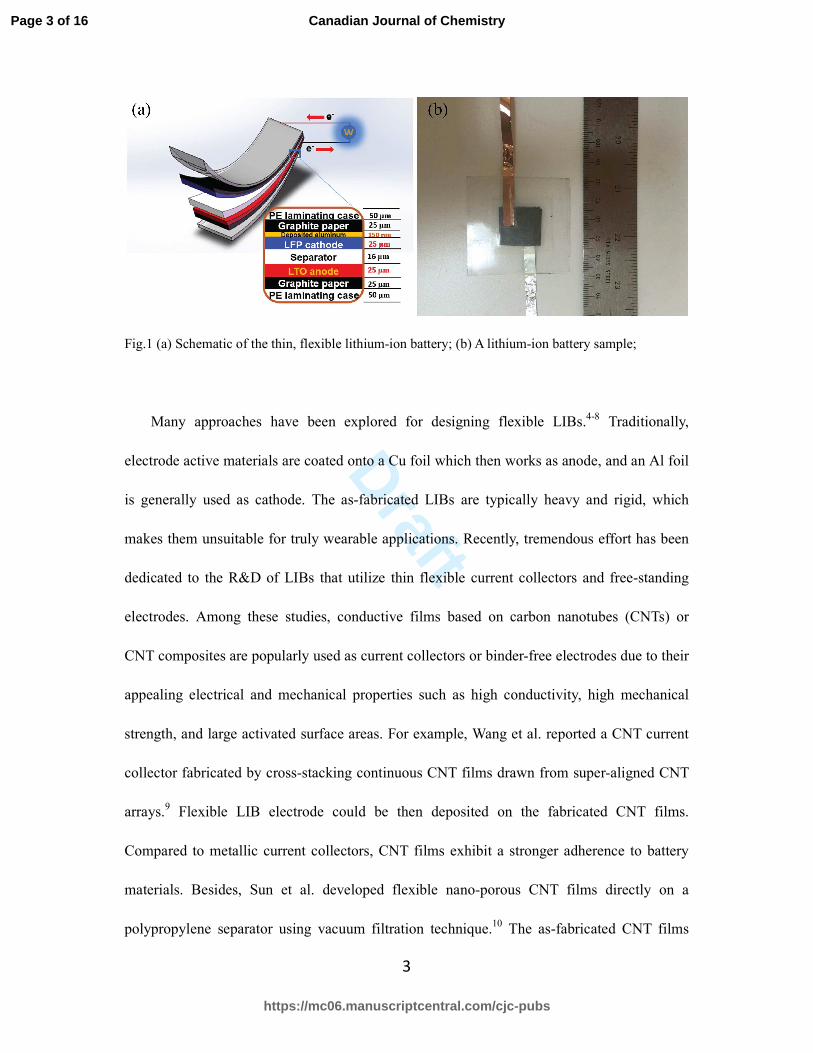
LIBs typically consist of several functional
layers (see Fig. 1a). When battery flexibility is desired, all of the battery components should
be flexible.1 Among the various functional layers, the current collectors affect critically the
battery performance, and their flexibility is typically difficult to achieve together with a high
conductivity.
Page 2 of 16
https://mc06.manuscriptcentral.com/cjc-pubs
Canadian Journal of Chemistry
Draft
3
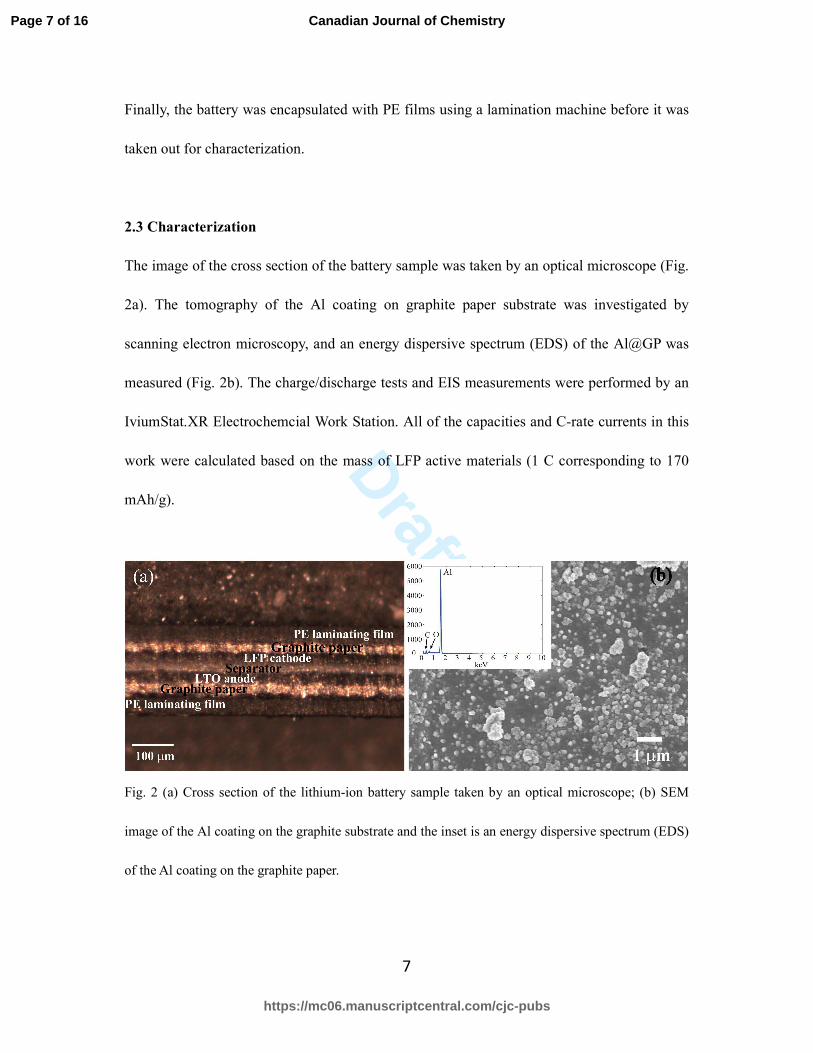
Fig.1 (a) Schematic of the thin, flexible lithium-ion battery; (b) A lithium-ion battery sample;
Many approaches have been explored for designing flexible LIBs.4-8 Traditionally,
electrode active materials are coated onto a Cu foil which then works as anode, and an Al foil
is generally used as cathode. The as-fabricated LIBs are typically heavy and rigid, which
makes them unsuitable for truly wearable applications. Recently, tremendous effort has been
dedicated to the R&D of LIBs that utilize thin flexible current collectors and free-standing
electrodes. Among these studies, conductive films based on carbon nanotubes (CNTs) or
CNT composites are popularly used as current collectors or binder-free electrodes due to their
appealing electrical and mechanical properties such as high conductivity, high mechanical
strength, and large activated surface areas. For example, Wang et al. reported a CNT current
collector fabricated by cross-stacking continuous CNT films drawn from super-aligned CNT
arrays.9 Flexible LIB electrode could be then deposited on the fabricated CNT films.
Compared to metallic current collectors, CNT films exhibit a stronger adherence to battery
materials. Besides, Sun et al. developed flexible nano-porous CNT films directly on a
polypropylene separator using vacuum filtration technique.10
The as-fabricated CNT films
Page 3 of 16
https://mc06.manuscriptcentral.com/cjc-pubs
Canadian Journal of Chemistry
Draft
4
were utilized as binder-free and current collector-free anodes in LIBs. An electrochemical
half-cell was fabricated using a CNT film as anode and a lithium-foil as counter electrode,
and the specific capacity of the CNT film anode was measured to be ~380 mAh/g. Later the
same group also fabricated an LIB electrode based on CNT/graphite-nanosheets (GN)
composite films with an optimized CNT/GN ratio of 2:1.11 The reversible capacity of the
CNT/GN electrode was found to be 375 mAh/g. More recently, Yoon et al. synthesized CNT
films via chemical vapor deposition followed by a direct spinning process.12
The CNT films
were then processed by a heating treatment to increase the crystalline perfection.
Experimental results showed that the electrode based on heat-treated CNT films exhibited a
higher capacity of ~446 mAh/g that was around twice as the case of the electrode based on
raw CNT films. Though CNT films feature great electrochemical properties for LIB
applications, the synthesis of CNT (or CNT-composite) films normally requires a
sophisticated process, and cost of such materials is high (~1000$ per gram), thus creating
significant barriers that prevent the utilization of LIBs in the wearable devices.
Flexible LIBs can be also produced by the mciro-electromechanical systems (MEMS)
fabrication technique in which the battery active materials are deposited on a flexible
substrate in sequence (e.g., in cathode-electrolyte-anode sequence).13,14
As an example, Su et
al. demonstrated a flexible LIB fabricated by a sequential deposition of a LiMnO2 cathode
layer, a LiPON electrolyte layer and a Li anode layer on a 70 µm thick stainless steel
substrate using the RF sputtering technique.13 The as-fabricated LIB had a capacity of 12.8
µAh when discharged at a current density of 5 µA/cm2. Also based on the MEMS fabrication
technique, Vieira et al. reported fabrication of a flexible LIB that used Ge as anode, LiCoO2
Page 4 of 16
https://mc06.manuscriptcentral.com/cjc-pubs
Canadian Journal of Chemistry
Draft
5
as cathode and LiPON as solid-state electrolyte.14 During the fabrication process, Si3N4 and
LiPO thin layers were also deposited onto the cathode and anode respectively to provide
electrical insulation and a battery chemical stability safeguard. The battery had a capacity of
~46 nAh/cm2. We note that in a MEMS fabrication process, expensive deposition equipments
such as RF-sputtering systems are generally required in order to have precise control of the
coated battery layer.
In this paper, we report a flexible lithium-ion battery using graphite-paper (GP) with
enhanced conductivity as current collectors (Fig. 1b). The enhancement of conductivity of GP
was achieved by depositing a sub-micron thick metal layer onto a commercial graphite paper
by physical vapor deposition (PVD). Particularly, we use an Al-deposited GP as the current
collector for cathode and a bare GP or a copper-deposited GP as the current collector for
anode. In this LIB, LiFePO4 (LFP) and Li4Ti5O12 (LTO) are used as cathode and anode active
materials, and a polyethylene (PE) nanostructured membrane is used as a separator.
2 Experimental
2.1 Chemicals and materials
LiFePO4, Li4Ti5O12 and PE membranes were purchased from Targray Technology
International Inc; Graphite papers (> 99%; thickness: ~25 µm) were purchased from Suzhou
Dasen Electronic; Multi-walled carbon nanotubes (MWCNTs) and copper powder (> 99.7%)
were obtained from Sigma-Aldrich. Al pellets (99.99%) are obtained from Kurt J. Lesker.
2.2 Battery sample fabrication
A highly conductive and flexible current collector was fabricated by depositing a sub-micron
Page 5 of 16
https://mc06.manuscriptcentral.com/cjc-pubs
Canadian Journal of Chemistry
Draft
6
thick aluminum or copper layer onto a graphite sheet by PVD (evaporative deposition,
Edwards High Vacuum Ltd.). The PVD was performed under a high vacuum condition (~10-7
mbar) with a deposition rate of 0.2 nm/s. Then, the graphite sheet with a metallic coating was
stored in N2-filled glove box for subsequent procedures. The obtained conductivity-enhanced
GP (abbreviated as Al@GP in the following) current collector can be then used as substrates
for deposition of LFP/PVDF to make LFP-Al@GP electrodes.
To synthesize the anode and cathode, LFP and LTO were first pre-mixed with MWCNT
in a mortar, respectively. Then mixture was then dispersed in polyvinylidene fluoride
(PVDF)/1-methyl-2-pyrrolidone solution using a magnetic stirrer for 4 h. The optimal weight
ratio of LFP (or LTO), MWCNT and PVDF was found to be 8:1:1. The obtained slurry was
then poured onto the current collector and made into a uniform wet-film using a Micrometer
Adjustable Film Applicator (MTI Cooperation). The composites were dried in a vacuum
furnace at 80 for 3 h, and then cut into 2*2 cm2 square-shaped electrodes. These electrodes
were then further dried at 110 for 12 h to ensure that the solvent (1-methyl-2-pyrrolidone)
in slurry was completely evaporated.
The lithium-ion batteries were finally assembled by stacking the as-prepared electrodes
together with a PE separator layer. 3 droplets (~0.15 mL) of electrolyte (1.0 M LiPF6)
dissolved in ethylene carbonate/dimethyl carbonate (EC/DEC) = 50/50 (v/v) from
Sigma-Aldrich were added to the battery during the stacking process. Note that the battery
assembly process was completed in a N2-filled glove box to avoid oxidation of electrolyte.
Page 6 of 16
https://mc06.manuscriptcentral.com/cjc-pubs
Canadian Journal of Chemistry
Draft
7
Finally, the battery was encapsulated with PE films using a lamination machine before it was
taken out for characterization.
2.3 Characterization
The image of the cross section of the battery sample was taken by an optical microscope (Fig.
2a). The tomography of the Al coating on graphite paper substrate was investigated by
scanning electron microscopy, and an energy dispersive spectrum (EDS) of the Al@GP was
measured (Fig. 2b). The charge/discharge tests and EIS measurements were performed by an
IviumStat.XR Electrochemcial Work Station. All of the capacities and C-rate currents in this
work were calculated based on the mass of LFP active materials (1 C corresponding to 170
mAh/g).
Fig. 2 (a) Cross section of the lithium-ion battery sample taken by an optical microscope; (b) SEM
image of the Al coating on the graphite substrate and the inset is an energy dispersive spectrum (EDS)
of the Al coating on the graphite paper.
Page 7 of 16
https://mc06.manuscriptcentral.com/cjc-pubs
Canadian Journal of Chemistry
Draft
8
3 Results and Discussion
3.1 Tomography and EDS of Al@GP
The tomography of Al@GP was studied by scanning electron microscopy. As shown in Fig.
2b, Al particles could aggregate to form clusters with the size ranging from tens to hundreds
of microns, thus leading to a high aspect ratio and large activated surface area of the electrode.
The EDS result suggests a good purity of the Al coating. The existence of oxygen is due to
the passivation of the Al coating. The passivation layer is generally 2-5 nm thick and would
not affect the electrochemical properties of the fabricated electrode.15
3.2 Electrochemical performance of the LFP/Al@GP electrode.
Fig. 3 charge/discharge voltage curves of the half cells with the rate of 0.05 C. (a) LFP-Al (foil), (b)
LFP-Al@GP (Al enhanced GP), and (c) LFP-GP (pure GP). (d) Equivalent circuit and electrochemical
impedance spectra of the LFP-Al@GP electrode, LFP-Al@GP electrode and a reference LFP-Al current
Page 8 of 16
https://mc06.manuscriptcentral.com/cjc-pubs
Canadian Journal of Chemistry
Draft
9
collector.
The electrochemical performance of the LFP-Al@GP electrode was characterized by the
galvanostatic charge-discharge tests and EIS measurements. A half-cell battery with an active
area of 2*2 cm2 was fabricated using LFP-Al@GP as the cathode and pure GP as the anode.
The performance of this half-cell battery was compared with its two counterparts in which the
cathode was fabricated by coating LFP onto an Al foil current collector (abbreviated as
LFP-Al) or by coating LFP onto a GP current collector (abbreviated as LFP-GP). Note that
the anode of reference half-cell batteries was also a 2*2 cm2 sized GP, the same as used in the
LFP-Al@GP battery. The lithium-ion insertion/extraction properties of the LFP-Al cathode
and LFP-Al@GP cathode were investigated by galvanostatic charge-discharge measurements.
Fig. 3 represents the voltage curves in the first cycle of the charge/discharge test for batteries
using the LFP-Al (Fig. 3a), LFP-Al@GP (Fig. 3b) and LFP-GP (Fig. 3c) with a 0.05 C
charge/discharge rate. All the half-cells feature a ~ 3.2 V open circuit voltage. The capacity of
the LFP-Al@GP//GP cell at 0.05 C discharge rate was 104.8 mAh/g with a coulombic
efficiency of 71% (Fig. 3a). This was comparable to the performance of the half-cell battery
using LFP-Al cathode that had a capacity of 113 mAh/g and a coulombic efficiency of 67.7%
(see Fig. 3b). These results indicated that the Al@GP could be an excellent current collector
for the cathode as its electrochemical properties are virtually identical to pure Al foil
electrodes. Besides, we also investigated how thickness of the coated aluminum current
collector would affect the performance of the half-cell battery. Experimentally, we fabricated
several LFP-Al@GP cells with the thickness of coated aluminum layers ranging from 50 nm
Page 9 of 16
https://mc06.manuscriptcentral.com/cjc-pubs
Canadian Journal of Chemistry
Draft
10
to 200 nm with a 50 nm step. As a matter of fact, these LFP-Al@GP cells show virtually
identical performances in the charge-discharge measurements. We, therefore, conclude that
the thickness of the aluminum layer has an insignificant effect on the electrochemical
properties of the LFP-Al@GP electrode.
To investigate the conductivity of a cathode, EIS measurements of LFP-Al@GP were
performed, and the results were compared to those of LFP-Al and LFP-GP. Fig. 3d shows the
Nyquist plots of the fresh LFP-Al//GP, LFP-Al@GP//GP, and LFP-GP//GP half-cells after the
first 0.2 C charge-discharge cycle. Nyquist plots are composed of a depressed semicircle in
the high-to-medium frequency region together with a slope in the low frequency region.
According to the order of decreasing frequency, the EIS spectra can be divided into three
distinct regions. The first intercept on the real axis in Fig. 3d (high frequency region) gives
the equivalent series resistance (ESR), Rs, which is a bulk electrolyte resistance. The second
intercept (lower frequency region) gives a sum of the electrolyte resistance, Rs, and the
charge transfer resistance, Rct, which is the electrode/electrolyte interfacial resistance.16 The
values of the charge-transfer resistance Rct of the LFP-Al@GP electrode was 920 Ω, which
are higher than that of the LFP-Al (Rct = 400 Ω), but is significantly lower than that of the
LFP-GP. Note that the Al@GP is much more flexible and lighter compared to a pure Al foil.
All these results indicated that the Al@GP fabricated by PVD method, could be an excellent
candidate of current collector for highly flexible LIBs. However, it is meaningless to discuss
more of the batteries’ performance when GP was used directly as the anode without any
modification or improvements.
Page 10 of 16
https://mc06.manuscriptcentral.com/cjc-pubs
Canadian Journal of Chemistry
Draft
11
It is worth to note that that, if a GP is directly used as a current collector, coating of the
battery active materials onto a pure GP is challenging, since the coated layer tends to peel off.
Thus, yield of the corresponding electrodes is less than 10 %. However, yield of the
electrodes can experimentally reach almost 100%, if electrodes are made from a GP enhanced
with a sub-micron thick metal layer. Therefore, depositing a submicron thick layer onto a GP
not only enhances the conductivity of the current collector, but also mechanically improves
the adhesion between the battery active materials and the current collector, thus facilitating
the subsequent battery assembly process and its reliability.
3.3 Assembly and Electrochemical Behavior of the LFP-Al@GP//LTO-GP Flexible full
Battery
Since LFP and LTO have the well-matched theoretical capacities of 170 mAh/g and 175
mAh/g, and the LFP/Al@GP electrode showed excellent electrochemical performance that is
comparable to that of LFP -Al, we proceeded with a full battery assembly. We fabricated a
thin, and flexible LFP-Al@GP//LTO-GP full battery using the flexible LFP-Al@GP cathode
and the LTO-GP anode.
To assemble a full battery, the integrated cathode was first attached to the sticky side of a
polyethylene (PE) lamination film. Then we stacked the PE separator on top of the cathode,
and added three droplets of LiPF6 electrolyte. The counter electrode and another PE
lamination film were then stacked to the battery structure one after another. Finally, the full
battery was then encapsulated using a laminating machine. All of these assembly processes
Page 11 of 16
https://mc06.manuscriptcentral.com/cjc-pubs
Canadian Journal of Chemistry
Draft
12
were carried out in a N2-filled glove box.
Fig. 4 Characterization of the LFP-Al@GP//LTO-GP full battery. (a) Charge/discharge voltage curves
of the battery with different charge-discharge rates. (b) Capacity and coulombic efficiency of the
battery with different charge-discharge rates for 35 cycles. (c) Voltage curves of the flat battery (red
line) and a bent battery (blue line). The bending radius of the battery is ~1 cm. (d) A LED was lit up
by a bent full battery. The inset demonstrates the excellent flexibility of the full battery.
The electrochemical properties of a full battery were investigated using charge /discharge
cyclic analysis with different charge/discharge rates (from 0.1 C to 1 C) as shown in Fig. 4a.
Page 12 of 16
https://mc06.manuscriptcentral.com/cjc-pubs
Canadian Journal of Chemistry
Draft
13
Consistent with the theoretical value of a LFP-LTO battery, the operating voltage of this full
battery was found to be ~1.9 V. As shown in Fig. 4a and b, the LFP-Al@GP//LTO-GP battery
had an excellent rate capacity, which was calculated to be 120.2, 107.8, 81.8 and 49.4 mAhg-1
at 0.1, 0.2, 0.5, and 1 C, respectively. It can be clearly seen that the discharge capacities
exhibit a tendency to decrease with the increment of current density; however, the voltage
plateau still remained flat even when current density is up to 1 C, indicating an excellent
charge/discharge performance. Moreover, after a series of tests under different
charge/discharge rates, the discharge capacity of the battery was still as high as 103.8 mAhg−1,
when the rate turned back to 0.2 C. This suggests that the structure of each components of the
full battery remained intact after subjecting to high current densities. The coulombic
efficiencies of the full battery were > 94 % during the whole cycle.
Due to the small thickness and high flexibility of the metal-enhanced GP current
collectors and the as-integrated LFP-Al@GP and LTO-GP electrodes, the full battery shows
excellent flexibility. The effect of bending on the performance of the flexible battery was also
investigated. Fig. 4c shows the charge/discharge measurement of the bent battery at 0.2 C
after 25 charge/discharge cycles under different rates. Compared with the flat state, only a
slight overpotential was observed, and a 2% decrease in capacity was found. What’s more,
the flexible battery showed an excellent cyclic stability both under flat and bent states (see
Fig. 4b and c). The retention capacity of the bent battery was ~92% of that of the flat battery
even after the battery undergoes 25 charge/discharge cycles. Furthermore, we note that even
after bending the battery for another 5 charge/discharge cycles, more than 93% of the
Page 13 of 16
https://mc06.manuscriptcentral.com/cjc-pubs
Canadian Journal of Chemistry
Draft
14
capacity could be still restored if the battery is released. In Fig. 4d, we demonstrate that a
LED could be lit up by the battery bent at a 1 cm radius.
Conclusions
In summary, an ultra-thin flexible battery with total thickness of less than 250 µm was
successfully fabricated by using conductivity-enhanced metal-deposited GP current collector.
To fabricate this highly flexible and conductive current collector, we deposit sub-micron thick
metallic layers onto the GP using PVD technique. Compared to traditional current collectors
based on pure metal (such as Al or Cu) foils, the proposed current collector is advantageous
due to its light weight, high flexibility and improved surface adhesion for depositing battery
electrode materials. The battery uses LiFePO4 and Li4Ti5O12 as the cathode and anode
materials, and PE membrane soaked in LiPF6 as a separator. The battery could achieve a rate
capacity of ~100 mAhg-1 under standard 0.2 C charge/discharge rate. Besides, the battery
could retain its capacity even after intensive cyclic charge/discharge operation. During all the
battery operation, the coulombic efficiency of the battery remains above 94%. We believe
that this battery could find its niche markets in numerous fields relevant to portable or
wearable electronic devices.
References
(1) Gwon, H.; Hong, J.; Kim, H.; Seo, D.-H.; Jeon, S.; Kang, K. Energy & Environmental Science 2014, 7,
538.
(2) Zhou, G.; Li, F.; Cheng, H.-M. Energy & Environmental Science 2014, 7, 1307.
(3) Armand, M.; Tarascon, J.-M. Nature 2008, 451, 652.
(4) Li, N.; Chen, Z.; Ren, W.; Li, F.; Cheng, H.-M. Proceedings of the National Academy of Sciences 2012,
109, 17360.
Page 14 of 16
https://mc06.manuscriptcentral.com/cjc-pubs
Canadian Journal of Chemistry
Draft
15
(5) Koo, M.; Park, K.-I.; Lee, S. H.; Suh, M.; Jeon, D. Y.; Choi, J. W.; Kang, K.; Lee, K. J. Nano letters 2012,
12, 4810.
(6) Vlad, A.; Reddy, A. L. M.; Ajayan, A.; Singh, N.; Gohy, J.-F.; Melinte, S.; Ajayan, P. M. Proceedings of
the National Academy of Sciences 2012, 109, 15168.
(7) Wei, D.; Haque, S.; Andrew, P.; Kivioja, J.; Ryhänen, T.; Pesquera, A.; Centeno, A.; Alonso, B.; Chuvilin,
A.; Zurutuza, A. Journal of Materials Chemistry A 2013, 1, 3177.
(8) Liu, Y.; Gorgutsa, S.; Santato, C.; Skorobogatiy, M. Journal of the Electrochemical Society 2012, 159,
A349.
(9) Wang, K.; Luo, S.; Wu, Y.; He, X.; Zhao, F.; Wang, J.; Jiang, K.; Fan, S. Advanced Functional Materials
2013, 23, 846.
(10) Li, X.; Yang, J.; Hu, Y.; Wang, J.; Li, Y.; Cai, M.; Li, R.; Sun, X. Journal of Materials Chemistry 2012, 22,
18847.
(11) Hu, Y.; Li, X.; Wang, J.; Li, R.; Sun, X. Journal of Power Sources 2013, 237, 41.
(12) Yoon, S.; Lee, S.; Kim, S.; Park, K.-W.; Cho, D.; Jeong, Y. Journal of Power Sources 2015, 279, 495.
(13) Su, C.-H.; Hsueh, T.-H.; Jheng, Y.-R.; Yu, Y.-J.; Jan, D.-J.; Wang, M.-C. ECS Transactions 2014, 59, 103.
(14) Vieira, E.; Ribeiro, J.; Sousa, R.; Correia, J.; Goncalves, L. Journal of Micromechanics and
Microengineering 2016, 26, 084002.
(15) Evertsson, J.; Bertram, F.; Zhang, F.; Rullik, L.; Merte, L.; Shipilin, M.; Soldemo, M.; Ahmadi, S.;
Vinogradov, N.; Carlà, F. Applied surface science 2015, 349, 826.
(16) Rakhi, R.; Chen, W.; Cha, D.; Alshareef, H. Nano letters 2012, 12, 2559.
Page 15 of 16
https://mc06.manuscriptcentral.com/cjc-pubs
Canadian Journal of Chemistry
Draft
16
Figure capations
Fig.1 (a) Schematic of the thin, flexible lithium-ion battery, and (b) a lithium-ion battery
sample
Fig.2 (a) Cross section of the lithium-ion battery sample taken by an optical microscope; (b) SEM
image of the Al coating on the graphite paper substrate and the inset is an energy dispersive spectrum
(EDS) of the Al coating on the graphite paper.
Fig. 3 charge/discharge voltage curves of the half cells with rate of 0.05 C. (a) LFP-Al (foil),
(b) LFP-Al@GP (Al enhanced GP), and (c) LFP-GP (pure GP). (d) Equivalent circuit and
electrochemical impedance spectra of the LFP-Al@GP electrode, LFP-Al@GP electrode and
a reference LFP-Al current collector.
Fig. 4 Characterization of the LFP-Al@GP//LTO-GP full battery. (a) Charge/discharge
voltage curves of the battery with different charge-discharge rates. (b) Capacity and
coulombic efficiency of the battery with different charge-discharge rates for 35 cycles. (c)
Voltage curves of the flat battery (red line) and a bent battery (blue line). The bending radius
of the battery is ~1 cm. (d) A LED was lit up by a bent full battery. The inset demonstrates the
excellent flexibility of the full battery.
Page 16 of 16
https://mc06.manuscriptcentral.com/cjc-pubs
Canadian Journal of Chemistry